1
415 Service Manual
SERVICE MANUAL
415 Series Axle
Issue 1 - January 2002
415 Service Manual
CONTENT:
1 INTRODUCTION
. . . . . . . . . . . . . . . . . . . . . . . . . . . . . . . . . . . . . . . . . . . . . . . . . . . . . . . . . . . . . . . Page - 1 -
2 GENERAL DESCRIPTION . . . . . . . . . . . . . . . . . . . . . . . . . . . . . . . . . . . . . . . . . . . . . . . . . . . . . . . . Page - 1 3 IDENTIFICATION . . . . . . . . . . . . . . . . . . . . . . . . . . . . . . . . . . . . . . . . . . . . . . . . . . . . . . . . . . . . . . . Page - 1 4 GENERAL SERVICE INFORMATION . . . . . . . . . . . . . . . . . . . . . . . . . . . . . . . . . . . . . . . . . . . . . . .
4.1 Routine Maintenance . . . . . . . . . . . . . . . . . . . . . . . . . . . . . . . . . . . . . . . . . . . . . . . . . . . . . . .
4.2 Lubricants . . . . . . . . . . . . . . . . . . . . . . . . . . . . . . . . . . . . . . . . . . . . . . . . . . . . . . . . . . . . . . . .
4.3 Greases . . . . . . . . . . . . . . . . . . . . . . . . . . . . . . . . . . . . . . . . . . . . . . . . . . . . . . . . . . . . . . . . .
4.4 Brake Fluid – IMPORTANT . . . . . . . . . . . . . . . . . . . . . . . . . . . . . . . . . . . . . . . . . . . . . . . . . .
4.5 Liquid Sealant . . . . . . . . . . . . . . . . . . . . . . . . . . . . . . . . . . . . . . . . . . . . . . . . . . . . . . . . . . . . .
4.6 Fasteners – Tightening Torque . . . . . . . . . . . . . . . . . . . . . . . . . . . . . . . . . . . . . . . . . . . . . . .
4.7 Axle Backlash Figures . . . . . . . . . . . . . . . . . . . . . . . . . . . . . . . . . . . . . . . . . . . . . . . . . . . . .
Page
Page
Page
Page
Page
Page
Page
Page
-
2
2
2
2
2
2
2
3
-
5 415 AXLE ASSEMBLIES . . . . . . . . . . . . . . . . . . . . . . . . . . . . . . . . . . . . . . . . . . . . . . . . . . . . . . . . Page - 4 5.1 Section ‘A’ - Pinion Cartridge Assembly . . . . . . . . . . . . . . . . . . . . . . . . . . . . . . . . . . . . . . . . Page - 4 5.2 Section ‘B’ - Differential Assembly . . . . . . . . . . . . . . . . . . . . . . . . . . . . . . . . . . . . . . . . . . . . Page - 7 5.3 Section ‘C’ - Planet Carrier Assembly . . . . . . . . . . . . . . . . . . . . . . . . . . . . . . . . . . . . . . . . . . Page - 9 5.4 Section ‘D’ - Hub Assembly . . . . . . . . . . . . . . . . . . . . . . . . . . . . . . . . . . . . . . . . . . . . . . . . . . Page - 105.5 Section ‘E’ - Brake Assembly . . . . . . . . . . . . . . . . . . . . . . . . . . . . . . . . . . . . . . . . . . . . . . . Page - 12 5.6 Section ‘F’ - Axle Arm Assembly . . . . . . . . . . . . . . . . . . . . . . . . . . . . . . . . . . . . . . . . . . . . Page - 14 5.7 Section ‘G’ - Hydrostatic Dropbox Assembly . . . . . . . . . . . . . . . . . . . . . . . . . . . . . . . . . . . Page - 15 6 CROWN WHEEL AND PINION ASSEMBLY. HYDROSTATIC VERSION.
. . . . . . . . . . . . . . . . Page - 17 -
7 SPIRAL BEVEL GEAR TOOTH CONTACT . . . . . . . . . . . . . . . . . . . . . . . . . . . . . . . . . . . . . . . . . Page - 21 -
415 Service Manual
1
INTRODUCTION
Spare parts for Newage axles may only be obtained from the original equipment manufacturer and not directly
from Newage. Always quote your vehicle/machine serial number and axle serial number – see section titled
'Identification.'
If possible, the repair/service should be carried out in a clean environment. Where this is not possible and the
work must be completed on site, appropriate measures must be taken to ensure that dirt or foreign matter does
not enter the unit. Newage axles are designed to operate in the arduous conditions found in the construction
industry; providing they are maintained regularly they will provide the service our customers expect from Newage
products.
2
GENERAL DESCRIPTION
The 415 series axle is a double reduction unit, with oil immersed, multi-plate disc brakes.
The centre casing houses the 1st reduction spiral bevel pinion and crown wheel (fixed to a 4 pinion differential),
the oil immersed brakes and the 2nd reduction planetary assembly. The axle shafts are fully floating (i.e. not
subjected to wheel loads) with the wheel hubs supported on opposed tapered roller bearings.
3
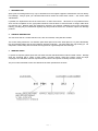
IDENTIFICATION
If spares are required, please quote the axle series and the vehicle/machine model and serial number. Newage
axles are produced with a variety of track widths, mounting centres, wheel hub centres, ratios and input
couplings to suit individual customer requirements, therefore it is important to identify the axle correctly
The part number allocated to each axle describes the basic specification as below.
Page - 1 -
415 Service Manual
4
GENERAL SERVICE INFORMATION
4.1 Routine Maintenance
Ÿ
Ÿ
Ÿ
Ÿ
Ÿ
Ÿ
Check for oil leaks around joints and seals:
Check wheel nut tightness:
Check wheel hub bearing adjustment:
Check axle Arm/Maincase joint securing bolts:
Check Half Shaft bolts:
Check Prop-Shaft Nuts:
Weekly
Weekly
1,000 hours
Monthly
Monthly
Monthly
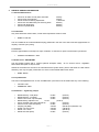
4.2 Lubricants
Only those lubricants shown below, or their direct equivalents must be used.
Ÿ
MOBIL FLUID 422
The oil is added via the combined filler/level plug positioned in the rear of the axle maincase (Approximate oil
capacity of 6 litres (10.6 pints)).
4.3 Greases
Pack the gaps between oil seal lips at major overhauls, or whenever a repair to these areas is performed.
Ÿ
CASTROL SPHEEROL L-EP2
4.4 Brake Fluid – IMPORTANT
The axle brakes operate with a mineral hydraulic fluid (ISO VG32). On no account must a "vegetable"
based brake fluid (SAE J1703) be used.
Whenever the brakes are serviced it is essential that the cylinder bores, pistons and seals are clean before
assembly, and may be lightly coated with one of the mineral based fluids shown below.
Ÿ
MOBIL DTE24
4.5 Liquid Sealant
The ‘Pinion Cartridge/Maincase’ & ‘Axle Arm/Maincase’ joint faces must be sealed with any of the following:
Ÿ
Ÿ
LOCTITE "595"
HERMETITE “RED”
4.6 Fasteners – Tightening Torque
Ÿ
Ÿ
Ÿ
Ÿ
Ÿ
Ÿ
Ÿ
Ÿ
Ÿ
Ÿ
Differential assy. stud (M10)
Differential assy. nut (M10)
H/B End end cover cap bolts (M6)
Differential brg. adjuster nuts
21 Nm
Pinion cartridge-main case bolts (M10)
Axle arm-main case bolts (M10)
Coupling nut (M20)
Wheel nuts. 5/8" B.S.F.
Wheel nuts. 18mm
Wheel hub bolts (M10)
56 Nm
56 Nm
28 Nm
(42 lbf.ft)
(42 lbf.ft)
(20 lbf.ft)
(15 lbf.ft)
56 Nm
(42 lbf.ft)
56 Nm
(42 lbf.ft)
340 Nm
(250 lbf.ft) Hydrostatic only
245 Nm
(180 lbf.ft)
270 Nm
(200 lbf.ft)
56 Nm
(42 lbf.ft)
Page - 2 -
415 Service Manual
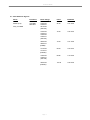
4.7 Axle Backlash Figures
Axles
Pin/wheel
Drive Flange
P.C.D.
Backlash
Series (415)
415-2000
250-2010
419-2180
419-2181
421-2180
(HS1410)
95.30
0.27-0.36
415-2180
415-2181
416-2180
416-2181
(HS1310)
79.40
0.22-0.30
420-2180
420-2181
(DIN90)
74.50
0.21-0.28
417-2180
417-2181
(DIN100)
84.00
0.23-0.32
418-2180
418-2181
(HS1100)
69.86
0.19-0.26
422-2180
(DIN120)
101.50
0.29-0.38
Assy 415-9820
Page - 3 -
415 Service Manual
5
415 AXLE ASSEMBLIES.
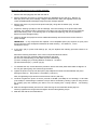
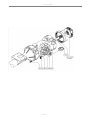
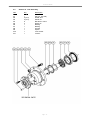
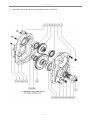
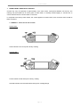
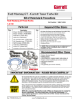
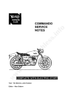
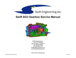
5.1 Section ‘A’ - Pinion Cartridge Assembly
Item
Qty
A1
A2*
A3
A4
1
1
1
As required
As required
As required
1
1
2
2
1
1
1
A5
A6
A7
A8
A9*
A10
A11*
Description
Input pinion cartridge
Input drive flange
Spiral bevel pinion
Shim 0.25mm
Shim 0.3mm
Shim 0.4mm
Spiral bevel wheel
Spacer (collapsible for non-hydrostatics)
Bearing cup
Bearing cone
Plain washer
Nut M20
Oil seal
(NB * Not valid for hydrostatic version)
Page - 4 -
415 Service Manual
Removing & Servicing the Pinion Cartridge Assembly
1
Remove the drain plug (E6) and drain the axle oil.
2
Remove both axle arms assy by removing bolts (F4). Withdraw the sun gear (F7). Remove 10
bolts (E3) around the pinion cartridge. Using the M10 extraction bolts (not supplied) remove the
crown wheel/differential assembly through the pinion cartridge aperture.
3
Remove the pinion nut (A10) from the pinion shaft (A3), along with the washer (A9), and the
coupling (A2).
4
Inspect the bearings (A7/A8) for wear and damage. If the inner bearing on the pinion shaft needs
replacing, use a bearing puller to extract the cone, taking care not to damage the shims positioned
behind the bearing cone. If the bearing cups or oil seals need replacing, they can be pressed or
drifted out of the cartridge housing.
5
Unpein 2 adjuster nuts (E2) and remove. Differential assembly will now be free to remove from the
pinion cartridge.
IMPORTANT – If any components are replaced a new collapsible spacer (A6) & pinion nut (A10) must
be used and the crown wheel/pinion backlash will need checking – see Section F, "crown
wheel/pinion set-up".
6
If the pinion (A3) or pinion head bearings (A7, A8) are replaced the following procedure needs to be
carried out:
Record the following information of the current components fitted as follows:(a) The new pinion (A3) mounting distance etched on the head.
(b) The new overall bearing (A7, A8) width of pinion head bearing.
(c) Pinion cartridge (A1) mounting distance constant for 110.35mm.
(d) Shim thickness (A4) = (100.85 -(a))-(b)
7
To assemble the unit, reverse the above procedure. Ensure the brake plates when fitted are aligned on
the sun gear spline giving oil access through the holes.
8
Tighten the pinion nut (A10) until the spacer (A6) collapses and all the end float between the pinion
bearings is taken up. Drag torque 1.92/2.48Nm. (17/22 lb.in).
Note, the tightening torque should not be less than 245 Nm (180 lb.ft).
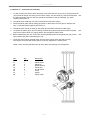
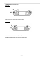
9
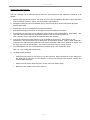
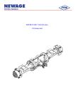
Continue to tighten the pinion nut until a pre-load of 59-98N (13.2-22lbf) for new bearings, or 29.5-59N
(6.6-13.2lbf) for used bearings is obtained. The pre-load is measured by binding a piece of string around
the coupling (A2) and measuring the load to turn the coupling with a spring balance – see drawing
below.
10 Refit the cartridge assembly into the main case ensuring the recommended sealing agent is
uniformly applied to the flange faces and tighten to M10 bolts tightening torque.
11 Refill the axle with the recommended oil
Page - 5 -
415 Service Manual
Page - 6 -
415 Service Manual
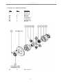
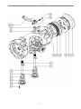
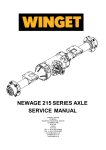
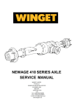
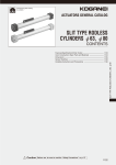
5.2 Section ‘B’ - Differential Assembly
Item
Qty
Description
B1
B2
B3
B4
B5
B6
B7
1
1
2
2
2
2
1
8
Diff case LH
Diff case RH
Diff wheel
Diff pinion
Thrust washer
Thrust washer
Diff spider (half)
Bolt M10
B8
8
Nyloc nut M10
Page - 7 -
415 Service Manual
Servicing the Crown Wheel & Pinion
1.
Remove the axle arm and sun gear - see Section A.
2.
Remove the pinion cartridge assembly – see Section A.
3.
The pinion cartridge/differential assembly can now be withdrawn through the pinion cartridge
aperture.
4.
Unpein and remove adjuster nuts (E2). The differential assembly is now free.
5. Remove nuts (B8) and bolts if necessary (B7). The crown wheel (A5) is now loose and the
differential assembly will split into 2 halves.
6.
Inspect all gears and bearings for damage and wear and replace if necessary.
7.
To assemble reverse the above procedure.
8.
If new differential bearings (E8) are fitted, it will be necessary to check the bearing pre-load and
crown wheel/pinion backlash - see Section F.
Page - 8 -
415 Service Manual
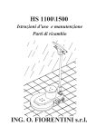
5.3 Section ‘C’ - Planet Carrier Assembly
1.
To gain access to the planet carrier assembly, remove the axle arm assy (F3) by removing the bolts
(F4) around the flange connecting it to the centre casing. The axle shaft (F1) will now be exposed and
the spline projecting from the axle arm should be examined for wear and damage. If it needs
replacing see section A.
2.
The planet carrier assembly can now be removed from the centre casing.
3.
Check the planet gears and the mating gear teeth on the annulus and sun gear for damage and
wear. If the latter needs replacing see section A.
4.
The planet gears should run freely on the planet pins and without excessive radial "play".
5.
To replace the planet gears, pins or bearings, drift the spring dowel (C8) which locates the planet
(C2) into the planet carrier (C1), lightly drift the pins through the planet carrier.
pins
6.
Before reassembling the unit, remove the old spring dowels (C8) from the planet pins (C2), and fit
spring dowels (C8) after reassembling the unit.
new
7.
Locate the planet carrier assembly back into the centre casing and fit the axle arm assy
ensuring the recommended sealing agent is uniformly applied to the sealing faces.
NOTE: When servicing planetary sets all three gears and bearings must be replaced.
Item
Qty
Description
C1
C2
C3
C4
C5
C6
C7
C8
1
3
3
3
6
1
1
3
Planet carrier
Planet pin
Needle bearing
Planet gear
Thrust washer
Circlip
Spacer
Spring dowel
Page - 9 -
415 Service Manual
5.4
Section 'D' - Hub Assembly
Item
Qty
Description
D1
D2
D3
D4
D5
D6
D7
D8
D9
D10
D11
1
5 (or 6)
5 (or 6)
8
2
1
1
1
1
1
1
Hub (i.e. per side)
Wheel stud
Wheel nut
Bolt M10 x 30mm
Dowel pin
Bearing
Bearing
Oil seal
Spacer
Lock washer
Locknut
Page - 10 -
415 Service Manual
Servicing the Hub Assembly
The hub assembly can be serviced with the axle arm still connected to the maincase. Procedure is as
follows:1. Remove bolts (D4) that secures the axle shaft (F1) to the hub and withdraw the shaft. Inspect the spline
form for damage and wear. (Flat on hub is provided to aid extraction).
2.
Straighten locking tab ears on lockwasher (D10), undo lock nut (D11) remove lockwasher (D10) and
bearing spacer (D9).
3.
The hub (D1) can now be withdrawn off its support bearings.
4.
Examine all bearings and oil seals for damage and wear and replace if necessary.
5.
The bearing cups (D6 & D7) can be drifted out of the hub (D1) if they need replacing. When fitting
cups (D6 & D7) ensure that they are aligned squarely to the bores before pressing in.
Note: If the brg. (D7) is replaced oil seal (D8) will also need replacing.
6.
If the oil seal shield (F2) needs replacing it can be drifted off the axle arm. When drifting on the
replacement, care must be taken not to damage the oil seal rubbing surface. Apply "Loctite" grade 601
to both the arm and seal housing diameters only before assembly. Clean off any residual on fitment. Do
not apply any to the oil seal diameter. This must be kept clean from any foreign ingress.
7.
To reassemble the hub unit, reverse the above procedure using a new lockwasher (D10).
new
Note: Fit a new locking tab washer (D10).
8.
To adjust the hub bearings.
Ÿ
Tighten the lock nut (D11) to a torque of 140 Nm (100 lb.ft). When checking the torque setting turn
the wheel hub a few turns in each direction to ensure the bearings have "seated" correctly and
recheck tightening torque.
Ÿ
Slacken the nut back a distance equal to 2 tabs of the lock washer (D10).
Ÿ
Bend ear of lock washer over to secure the nut.
Page - 11 -
415 Service Manual
5.5
Section 'E' - Brake Assembly
(See Diagram on page 11)
Item
Qty
Description
E9
E10
E11
E12
E13/14
E15
E16
E17
E18
E19
E20
E21
1
2
2
2
2
1
1
1
1
2
2
12
Bleed screw
Piston ‘O’ ring
Brake Piston
Piston ‘O’ ring
External operating lever
RH return spring
LH return spring
RH hand brake cover
LH hand brake cover
Brake cam ‘O’ ring
Brake cam ‘O’ ring
M6 Cap head bolt
F8
F9
F10
F11
F12
F13
F14
2
4 (or 2)
4 (or 2)
1
1
2
2
Brake spacer plate
Sintered brake disc
Fixed brake plate
RH Brake cam
LH Brake cam
Lever Clamp bolt
Lever Clamp nut
IMPORTANT – The axle brakes operate with a mineral hydraulic fluid ISO VG32 Specification. On no
account must a "vegetable" based brake fluid (SAE J1703) be used.
1.
To gain access to the brakes, the procedure is the same as the planet carrier assembly – see
Section C.
2.
Remove the annulus gear (F6) and brake spacer plate (F8). The oil immersed brake discs (F9) and the
brake fixed plates (F10) can now be removed. Count the number of plates taken out as the
quantity can very with different axle specifications.
3.
Under normal operating conditions the brakes should last several years. The condition of the brakes
can be checked as follows:Ÿ
Ÿ
Sintered brake disc (F9) – not less than 4mm thickness.
Fixed brake plate (F10) – not less than 2mm thickness. Check for uneven wear or heat
discolouration on fixed plate.
4.
The brake piston (E11) can be removed from the cylinder and the seals (E10/E12) checked for
damage and wear.
5.
To reassemble, reverse the above procedure. Ensure that piston bores are clean and the brake
plates are assembled on the sun gear spline (F7) with the oil feed holes in the sintered plates correctly
aligned.
6.
To remove hand brake operating lever (E13) loosen nut (F14) and bolt (F13) and withdraw from
spline.
7.
Remove 6 M6 cap head bolts (E21) and withdraw cover (E18), spring (E16) and brake cam (F12).
8.
Repeat steps 6 and 7 for the opposite hand. Note. The cap, spring and brake cam are ‘handed’.
9.
To reassemble, reverse the above procedure replacing brake cam ‘O’ rings (E19) and (E20).
Page - 12 -
415 Service Manual
Page - 13 -
415 Service Manual
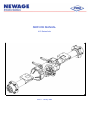
5.6 Section 'F' - Axle Arm Assembly
Item
Qty
Description
F1
F2
F3
F4
1
1
1
12
Axle shaft (i.e. per side)
Oil seal shield
Axle arm
Arm to Maincase bolts
1
Remove the bolts (F4) around the flange of the axle arm connecting it to the maincase and withdraw
the axle arm (F3). Note this can be done with or without the hub assembly fitted to the arm.
2.
Before refitting the axle arm, ensure the mating faces on the axle arm flange and centre case are
cleaned using Ambersil F10 Solvent and uniformly apply a continuous bead of the recommended sealing
agent (see section 4.5).
3.
Normally the axle arms only need removing to gain access to the components within the maincase,
and therefore for further information see previous sections.
Page - 14 -
415 Service Manual
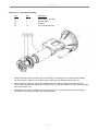
5.7 Section 'G' Hydrostatic Dropbox Assembly
(See Diagram on page 14)
Item
G1
G2
G3
G4
G5
G6
G7
G8
G9
G10
G11
G12
G13
G14
G15
G16
G17
G18
G19
Qty
10
3
4
4
1
2
1
1
1
1
1
1
1
10
10
1
1
1
1
Description
Bolt M12 x 45
Bolt M12 x 70
Stud M12
Nut M12
Bonded seal ½ BSP
Dowel
Bearing
Bearing
Roller bearing
Blanking plate (for transit)
Coupling
Oil seal
Drain plug ½ BSP
Nut M10
Stud
Transfer case LH
Transfer case RH
Input pinion
Input wheel
Dis-assembly procedure.
1.
Drain oil by removing drain plug (G13). Replace the plug when oil is drained.
2.
Remove nut, (A10) and withdraw coupling (G11).
3.
Remove 10 bolts, (G1) and 3 bolts (G2).
4.
Using 2 case bolts in the extraction holes and tighten evenly until the 2 case halves split.
5.
Remove RH case half (G17) which will expose the 2 gears.
6.
Remove pinion (G18) and wheel (G19). Note that the bearings (G7/G8/G9) will still be fitted to the
gears. Ensure bearing (A7/8) does not fall off spiral bevel pinion (A3).
7.
Check for wear and damage on gears. Check for wear on the seal (G12) paying particular attention to
the small circular spring. Remove if necessary.
Re-assembly procedure.
1.
Clean surface faces of case halves using Ambersil F10 Solvent and remove any remnants of old liquid
sealant.
2.
Replace if necessary seal (G12) and all bearings on the 2 gears before the next stage.
Place input pinion (G18) locating bearing in small bore in LH case half (G16) and tap home with mallet.
3.
Fit input wheel (G19) locating onto pinion spline and aligning mesh. Tap home with mallet.
4.
Apply continuous bead of liquid sealant to LH case half (G16).
5.
Fit RH case half (G17) locating on the 2 dowels (G6), ball bearing (G8) and roller bearing (G9).
6.
Fit and secure 13 case bolts ((G1) 10 off bottom and (G2) 3 off top) and tighten to the specified torque.
7.
Apply grease to seal (G12) and fit coupling, (G11) and nut (A10). Torque to the specified value.
Page - 15 -
415 Service Manual
8.
Remember also to fill with the recommended oil to the correct level.
Page - 16 -
415 Service Manual
6
CROWN WHEEL AND PINION ASSEMBLY. HYDROSTATIC VERSION.
The crown wheel and pinion is assembled using special purpose tools and electronic measuring
equipment. It is advisable, that in the unlikely event of failure or adjustment, the following actions
should be taken:
1.
Remove the drain plug (E6) and drain the axle oil from the maincase.
2.
Follow dis-assembly procedure for hydrostatic dropbox on page 15.
3.
Remove nuts (G14).
4.
Remove L/H transfer case (G16).
5.
Remove both axle arm assys by removing bolts (F4). Withdraw the sun gears (F7) only.
6.
Using 2 M10 extraction bolts (not supplied) remove crown wheel/differential assy
through the pinion cartridge aperture.
7.
Unpein and remove 2 adjuster nuts (E2).
remove from the pinion cartridge (A1).
8.
Gently tap pinion (A3) out of pinion cartridge bore and drift out bearing cups (A7).
9.
NOTE: When refitting any of the following new components crown wheel (A5), pinion
(A3), setting spacer (A6), pinion bearings (A7, A8) and shims (A4) the actions in item
10 need to be carried out.
10.
Record
a.
b.
c.
d.
e.
f.
g.
Differential assembly will now be free to
the following information of the current components fitted as follows:The pinion (A3) mounting distance etched on the head.
The overall bearing (A7, A8) width of pinion head bearing.
Current shim (A4) thickness.
The pinion head bearing (A7, A8) depth from cup to cone.
The overall length of the bearing setting spacer (A6).
The pinion tail bearing (A7, A8) depth from cup to cone.
Overall distance measured i.e a + b + c.
Record the following information of the new components fitted as follows:'a'
'b'.
'c'.
'd.'
'e'
'f'.
'g'.
New pinion mounting distance etched on the head.
New overall bearing (A7, A8) width at pinion head bearing.
New shim (A4) thickness.
New pinion head bearing (A7, A8) depth from cup to cone.
New overall length of the bearing setting spacer (A6).
New pinion tail bearing (A7, A8) depth from cup to cone.
Overall distance measured i.e 'a' +'b' + 'c'.
11.
Record the above information excluding ('c') and ('e') for new components to be fitted.
12.
Press or drift home pinion head bearing cone (A7, A8) onto pinion.
13.
Calculate the old shim arrangement as follows: a + b + c = g. (Note: use information
from 10).
14.
Calculate the new shim ('c'.) arrangement as follows: g - ('a' + 'b') = 'c'
15.
Calculate the new bearing setting spacer 'e' as follows:
Ÿ
Record the difference in new 'c' and old c shims = 'X'
if new 'c' is greater than old 'c' add 'X' if less than subtract 'X'.
Page - 17 -
415 Service Manual
Ÿ
Record the difference in new 'd' and old bearing d depth on tail bearing = 'Y'.
If new 'd' is greater than old 'd' add 'Y' if less than subtract 'Y'.
Ÿ
Record the difference in new 'f' and old f bearing depth of cup to cone on pinion
head = 'Z'. If new 'f' is greater than old f add 'Z' if less than subtract 'Z'
Ÿ
The new bearing setting spacer 'e' length is therefore solved by the equation
'e' = e (old) + 'X' + 'Y' + 'Z'. (Note: use information 10.)
16.
Fit new shims (A4) of new thickness 'c' into pinion cartridge head bore and press or drift
home new bearing cup (A7, A8) into bore trapping shims.
17.
Press new bearing cup (A7, A8) into pinion cartridge tail bore.
18.
Fit new bearing setting spacer (A6) of overall length 'e' over pinion diameter up to new
bearing fitted at pinion head end.
19.
Drift bearing cone over pinion tail end.
20.
Refit new crown wheel to diff case and secure by tightening the new nyloc nuts to
recommended tightening torque.
21.
Loosely screw the new bearing adjusting nuts to retain diff assy in pinion cartridge.
22.
Clean maincase, pinion cartridge and transfer case joint face using recommended
Ambersil F10 Solvent on joint face.
23.
Apply thin continuous bead of the recommended sealant to the maincase joint face and
LH transfer case joint face.
24.
Fit crownwheel/differential assy. through pinion cartridge aperture.
25.
Fit LH transfer case over pinion cartridge and tighten new nyloc nuts to recommended
tightening torque.
26.
Refit output wheel over pinion spline with inner part of the roller bearing fitted to the gear
and outer fitted with RH transfer case.
27.
Refit input pinion with bearings fitted to LH transfer case half.
28.
Clean transfer case joint faces using recommended Ambersil F10 Solvent.
29.
Apply a thin continuous bead of the recommended sealant to the LH transfer case joint
face.
30.
Refit the RH case, this will locate on the 2 dowels in one half of the case and will also
contain one half of the cylindrical roller bearing and the oil seal.
31.
Tighten 13 bolts to the recommended tightening torque.
32.
Smear the recommended grease on input seal.
33.
Clean drive flange, oil seal diameter prior to fitment.
34.
Fit new nyloc nut & tighten to recommended torque.
Page - 18 -
415 Service Manual
35.
Check the pinion assy is free to turn by hand prior to the next stage. Check pinion
bearing drag torque min 1.92/2.49Nm(17/22lbin), and no end float exists in assy by
using a dial test indicator on the drive flange, and applying hand pressure to record any
movement, i.e. maximum permitted end float 0.025mm.
If excessive end float exists on indicator increase the bearing setting spaces by same
amount. This will require a strip and rebuild to this stage.
36.
Set crownwheel & pinion backlash (See data sheets for drive flange variants) using new
adjuster nuts (E2) and tighten to 20Nm (15lbft) and tab into recess.
37.
Refit sungears through brake plate & diff wheel splines.
38.
Clean both axle arm and maincase joint faces with recommended Ambersil F10
solvent.
39
Apply a thin continuous bead of the recommended sealant to the maincase joints.
40.
Tighten 24 new bolts to the recommended tightening torque.
41.
Refit drain plugs and fill with the recommended axle oil
In the event of the pinion bearings and bearing setting spacer damage (with the pinion mounting distance only
available) the preferred procedure would be to carry out the following procedure.
1.
Repeat steps 1-10.
2.
Record the following information of the current and new components as follows:
(a)
(b)
(c)
(d)
(e)
(f)
Current fitted pinion (A3) mounting distance etched on the head.
New pinion (A3) mounting distance etched on the head.
The new overall width of the pinion head bearing (A7, A8).
Note: 415 axle mounting distance constant = 110.35
Shim thickness (A4).
Difference in (a) & (b).
Note: Overall length of the slave setting spacer (A6) = 24.30
3.
Press or drift home the new pinion head bearing cone (A7, A8).
4.
Calculate shims as follows:
Record the difference in (a) mounting distance and (b) mounting distance.
If (a) is greater than (b) subtract the difference (f).
If (a) is less than (b) add the difference (f).
For 415 axle use pinion cartridge mounting distance (d) = 73.00
(e) = (d + f) - c.
5.
Fit new shims (A4) at new thickness (e) into pinion cartridge head bore and press or drift home bearing
cup (A7, A8) into bore trapping shims.
6.
Press new bearing cup (A7, A8) into pinion cartridge head bore.
7.
Fit new slave bearing setting spacer (A6) of 24.30mm pre-determined length. This will enable end float
to exist.
8.
Follow points 19 to 22, 24 to 26, 28, 30, 31, 33, 34.
9.
Attach a dial test indicator to drive flange and apply hand pressure in forward and reverse direction and
check movement, i.e. end float and record movement.
10.
Reverse the procedure up to 8.
Page - 19 -
415 Service Manual
11.
Subtract the end float recorded from the slave bearing setting spacer (A6) = (24.30mm - 0.025mm) end float and fit new spacer of the calculated length.
Note: 0.025mm subtracted to obtain pinion bearing pre-load.
12.
Follow points 23 to 35, 37, 38, 39, 40 & 41 to rebuild the unit.
Page - 20 -
415 Service Manual
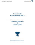
7
SPIRAL BEVEL GEAR TOOTH CONTACT
Contact may vary, but generally is approximately in the tooth centre, equi-spaced between root and tip. The
marking may be towards toe on some gears on both flanks, or marking crossed slightly i.e. towards toe on
convex flank and heel on concave flank or vice versa.
If, compared to the factory tooth contact, the contact appears as shown below, then corrective action should be
taken as follows:
7.1 ERROR 1: Pinion too far out of mesh
Convex flank
Contact further to toe and tip than factory marking.
Concave flank
Contact further to heel and tip than factory marking.
ACTION: Recheck and decrease shims below pinion cartridge flange.
Page - 21 -
415 Service Manual
7.2 ERROR 2: Pinion too far into mesh
Convex flank
Contact further to heel and root rather than factory marking.
Concave Flank
Contact further to toe and root than factory marking.
ACTION: Recheck and increase shims below pinion cartridge flange.
Page - 22 -