1
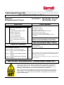
Turbo Speed Sensor Kit
Bill of Materials & Precautions
Part Numbers: 781328-0001: Street Kit
781328-0002: Pro Kit
Application:
All Catalog Garrett GT Turbos
Parts List
Item
Tools Needed
Description
Qty.
• 10mm open-end wrench
• Wire cutters / crimpers
1
Speed sensor 769366-0001
1
2
Spacer block
1
3
Layout (machining drawing) 776243
1
4
Installation Instructions
1
5
M4 x 0.70 x 18mm screw
1
• 6mm wrench or socket for gauge bracket
6
M4 x 0.70 x 20mm screw
1
• Wrench(es) to remove compressor housing and turbo if
7
M4 x 0.70 x 22mm screw
1
8
Main Wiring Harness 778178-0001
1
9
Power / Logger Pigtail 778178-0002
1
10
Gauge
1
11
Gauge Extension Harness 778178-0003
1
Table of Contents
Section
Page
General Installation Instructions
5
Section A: STREET KIT WITH GAUGE ONLY
9
Section B: PRO KIT WITH DATA LOGGING, NO
10
• Threadlocking compound
• Heat-shrink or electrical tape
• 20-gauge connectors for 12V power and ground
• Zip-ties to secure wiring harness
necessary
• NOTE: Bolt and fastener sizes may be different from one
model year to the next depending on OE specifications.
Different tools than those listed above may be required.
Recommended Other Items
• Factory Service Manual (if applicable)
• Safety glasses
• Anti-seize compound
GAUGE
Section C: STREET KIT WITH GAUGE AND DATA
11
LOGGER
Section D: MAXIMUM SPEED RECALL FUNCTION
12
Section E: MAPPING
12
PLEASE INSURE THAT THE PART NUMBER THAT HAS BEEN
RECEIVED WAS THE INTENDED PART NUMBER BEFORE
BEGINNING INSTALLATION.
See Honeywell Turbo Technologies’ return policy if the incorrect kit
has been ordered.
IMPORTANT INFORMATION - PLEASE READ CAREFULLY
We recommend that this Garrett product be installed by a qualified automotive technician. If
you have any doubts as to your ability to install this product, consult with a local automotive
repair company. Please be sure to carefully read all of the attached instructions prior to
starting the installation process. If you have any questions about the enclosed parts or the
instructions, call the distributor that you purchased the kit from for clarification.
Prior to the Garrett product installation, be sure that the vehicle is parked on a level surface
and the engine is cool. Engine fluids and components can be extremely hot following normal
vehicle operation. Avoid direct contact of engine fluids or components with your skin which
may cause personal injury.
Doc. 737639-34 (Rev -)
www.TurboByGarrett.com
1
Part Number: 781328-0001 or -0002
Turbo Speed Sensor Kit
IMPORTANT INFORMATION - PLEASE READ CAREFULLY
Return Policy
Only unused and complete merchandise will be accepted for return subject to inspection and
acceptance by Honeywell Turbo Technologies. No goods will be accepted without prior return
authorization from Honeywell Turbo Technologies. No returns are accepted after thirty (30) days
from original ship date from The Garrett Garage. All accepted returns are subject to a 20%
restocking charge - NO EXCEPTIONS.
Damaged Shipments
The customer must file a claim with the shipping company if goods arrive in a damaged condition.
The customer must also notify Honeywell Turbo Technologies with pertinent information.
Refused Shipments
Sending a shipment back to The Garrett Garage (or Honeywell) does not automatically give rise to a
complete refund or credit. Honeywell Turbo Technologies may, at its sole discretion require different
payment means for any shipment refused and then reshipped. It is the customer’s responsibility to
make all arrangements with Honeywell Turbo Technologies for disposition of refused shipments.
Shortage or Discrepancy Claim
Shortage or Discrepancy claims must be reported within forty-eight (48) hours of receipt of goods.
Honeywell Turbo Technologies will either issue a credit or send a replacement(s) at no charge.
Please contact [email protected] for instructions on how to address shortages or
discrepancies.
Limited Warranty
Honeywell Turbo Technologies warrants to the original purchaser of its Turbocharger Products that
such Turbocharger Products will, for a period of 1 year from date of shipment and subject to the
Limitations on Warranty, be free from defects in materials and workmanship. For approved warranty
claims Honeywell Turbo Technologies will, at its sole discretion, either credit the original purchaser
in an amount equal to the original purchase price, or replace the applicable Turbocharger Product
free of charge, within 60 days of Honeywell Turbo Technologies’ approval. This is purchaser’s sole
and exclusive remedy and provides the complete financial responsibility of Honeywell Turbo
Technologies for a warranty claim.
To be eligible for reimbursement, Customer must (a) submit all warranty claims to Honeywell Turbo
Technologies within 30 days of the discovery of the alleged Turbocharger Product defect; and (b)
complete and return a Returned Material Authorization Form. This form may be obtained from
Honeywell Turbo Technologies at [email protected].
When Honeywell Turbo Technologies requires the examination of a failed part, Honeywell Turbo
Technologies will promptly notify Customer and will await receipt of the failed part before further
processing the warranty claim. If Honeywell Turbo Technologies ultimately determines that the
failed part is covered under the Limited Warranty, Honeywell Turbo Technologies will reimburse
Customer for the actual cost of ground shipment for any part found to be defective.
Doc. 737639-34 (Rev -)
www.TurboByGarrett.com
2
Part Number: 781328-0001 or -0002
Turbo Speed Sensor Kit
IMPORTANT INFORMATION - PLEASE READ CAREFULLY
Limitations on Warranty
The Limited Warranty does not apply to any parts: (a) not used in accordance with Honeywell Turbo
Technologies’ written instructions (b) for which no fault is found; (c) that have been modified in any
manner not specifically approved by Honeywell Turbo Technologies; (d) for which an inspection
indicates that reasonable and proper installation and/or preventative care and maintenance has not
occurred; (e) that have been subject to damage attributable to or caused by misuse, abuse or
vandalism; mishandling, improper shipping or other transit related damage; acts of god or
insurrection; foreign object entry; any part not supplied by Honeywell Turbo Technologies; any repair,
maintenance or service by anyone other than Honeywell Turbo Technologies; or any other acts that
are beyond Honeywell Turbo Technologies’ reasonable control; or (f) attributable to parts not
supplied by Honeywell Turbo Technologies. Honeywell Turbo Technologies expressly disclaims any
and all warranties relative to the foregoing circumstances.
Honeywell Turbo Technologies shall not be liable to Customer under any circumstances for
any special, incidental or consequential damages, including without limitation, damage to or
loss of property other than for Turbocharger Products; damages incurred in installation,
repair or replacement; lost profits, revenue or opportunity; loss of use; losses resulting from
or related to downtime of Turbocharger Products; the cost of replacement transportation,
power, or compression; the cost of substitute products; or claims of third parties for such
damages, howsoever caused, and whether based on warranty, contract, and/or tort (including
negligence, strict liability or otherwise).
The Limited Warranty is the only warranty made by Honeywell Turbo Technologies for any of
its turbochargers and related parts and/or services, and is in lieu of and excludes all other
warranties, expressed or implied, including warranties of merchantability or fitness for a
particular purpose. Honeywell Turbo Technologies hereby disclaims all other warranties not
expressly set forth. Some jurisdictions do not allow for the exclusion of implied warranties, so
the above exclusions may not apply to you, however if implied warranties do apply they are
limited to the original purchaser and for a period of one (1) year from the date of shipment.
Diagnosing Your Vehicle
Do not rely on diagnostic software without seeking the advice of an ASE certified mechanic.
Diagnostic software should only be used as a general guideline to help you facilitate the repair of
your car. If you experience or suspect any malfunction of vital safety equipment, such as your brakes,
exhaust, motor, transmission, fuel delivery system, your car’s structural integrity or any other
potentially life threatening malfunction, cease driving your vehicle immediately and seek professional
help. Always consult your owner’s manual.
Vehicle Modification Notice
Any modifications to your car are AT YOUR OWN RISK. You should consult the owner’s manual and
service manual. You should also contact your car’s manufacturer to determine what effects
modifications may have on your safety, warranty, performance, etc. Please also contact your local
authorities to determine whether your intended modifications will make your car illegal to drive on
public roads. A vehicle modified by the use of competition parts may not meet the legal requirement
for use on public roads. It is your responsibility to comply with federal, state, and local laws prior to
driving your vehicle on public roads.
Doc. 737639-34 (Rev -)
www.TurboByGarrett.com
3
Part Number: 781328-0001 or -0002
Turbo Speed Sensor Kit
IMPORTANT INFORMATION - PLEASE READ CAREFULLY
OTHER PRECAUTIONS
Observe all safety precautions and warnings contained in the installation instructions. Wear eye and
ear protection and appropriate protective clothing. When working under or around the vehicle support
it securely with jack stands. Use only the proper tools. Exercise extreme caution when working with
flammable, corrosive, and hazardous liquids and materials.
LEGAL INFORMATION
The Garrett turbo kits are for use off the public roadways. Federal law restricts the removal or
modification of any part of a federally required emission control system on motor vehicles. Also,
many states have enacted laws which prohibit tampering with or modifying emission or noise control
systems. Vehicles which are not operated on public roadways may be exempt from certain
regulations, however the buyer is strongly urged to check all applicable local and state laws and is
ultimately responsible for compliance with the applicable laws and regulations.
Honeywell Turbo Technologies Contact Information
Please contact Honeywell Turbo Technologies at [email protected] for any questions
regarding this Shipping/Returns/Cancellation Policy, for notifications to Honeywell Turbo
Technologies, and for instructions on processing damaged shipments and authorized returns.
Honeywell Turbo Technologies
Garrett Independent Aftermarket
Honeywell International Inc.
3201 W. Lomita Blvd.
Torrance, CA 90505
www.TurboByGarrett.com
Doc. 737639-34 (Rev -)
www.TurboByGarrett.com
4
Part Number: 781328-0001 or -0002
Turbo Speed Sensor Kit
Installation Instructions
1. Remove the compressor housing from your
turbocharger. This may necessitate removing the
turbo from the vehicle, if it is already installed.
Typically the compressor housing is attached to the
turbo using a v-band clamp or bolted clamps.
Remove all bolts, clamps, and the wastegate
actuator – whatever is necessary to separate the
compressor housing from the turbo (see fig. 1).
Do not loosen the wastegate rod end or lock nut,
and do not adjust the actuator; simply unbolt its
bracket from the compressor housing.
1. Refer to the enclosed layout drawing 776243 and
find your particular Garrett turbo on sheet 2. Check
the turbo nameplate for part number. Otherwise,
cross-reference www.TurboByGarrett.com or your
Garrett catalog to confirm your turbo part number,
or call a distributor if you are unsure. Once you
have identified the part number, highlight the
correct row in the table for future reference. The
dimensions in this table refer to the views on sheet
1 of this drawing; these are instructions for the
machinist to modify your housing. For example, if
you have a Disco Potato turbo (GT2860RS) part
number 739548-1, or -5 or -11, highlight row 18.
You will only need the dimensions listed in this row
(see figure 2).
2. Take your compressor housing and the
highlighted layout 776243 (all sheets) to a qualified
machine shop. Make sure the machinist is capable
of meeting the tolerances on the drawing and
knows which row of dimensions to use before
agreeing to pay for the work. You may want to
supply the machine shop with the spacer, screw and
speed sensor so they can test-fit the parts in the
housing (see figure 3).
Clamp bolts
Fig. 1
Fig. 2
Sensor
Spacer
M4 Screw
Fig. 3
NOTE: On the machining Layout (776243 sheet 1),
datum A is always the main compressor housing
mating surface, which is a machined surface around
the perimeter of the housing, and is usually inset by
several millimeters.
Doc. 737639-34 (Rev -)
www.TurboByGarrett.com
5
Part Number: 781328-0001 or -0002
Turbo Speed Sensor Kit
Installation Instructions
4. Once the housing is machined, install the spacer
with the supplied M4 screw. There are different
lengths of screws supplied in the kit; the layout
drawing shows which screw to use on each turbo.
Do not torque the screw at this point. If your
housing has a ported shroud and the machined
spacer pocket has broken through to the inside,
coat the outside of the spacer with RTV or similar
sealant to prevent an air leak past the spacer (see
figure 4).
Fig. 4
4. Test fit the speed sensor. If the lock nut is not
accessible by wrench once installed, apply a
threadlocking compound that will cure slowly
enough to allow adjustment and final tightening.
Install the speed sensor loosely in the housing – do
not tighten the lock nut yet.
IMPORTANT: Make sure the tip of the sensor is
approximately flush with the inside contour of the
housing. (see figure 5). Tighten the M4 spacer
screw once the sensor has been installed in the
housing.
Sensor Tip
Fig. 5
4. Count the number of blades on your compressor
wheel, including small (splitter) blades. Record this
number below; you will need it later (see figure 3).
Fig. 2
Number of Compressor Wheel Blades:___________
4. Install the housing on the turbocharger with its
bolts and clamps. Make sure housing orientation is
correct. Reinstall the wastegate actuator with
bracket. Tighten and torque the clamping bolts,
according to the tabulated columns “Comp. Housing
Clamp Bolt Torque” and “Clamp Bolt Thread Type”
on the layout (776243) for your turbocharger.
Doc. 737639-34 (Rev -)
Full Blade
www.TurboByGarrett.com
Splitter Blade
Fig. 6
6
Part Number: 781328-0001 or -0002
Turbo Speed Sensor Kit
Installation Instructions
6. Setting the sensor depth: if the turbocharger is still in the vehicle, ensure that there is
enough space to adjust the sensor by turning it in and out. Also ensure there is sufficient
space to turn the compressor wheel by hand. If not, remove the turbocharger from the
vehicle. Slowly turn the sensor clockwise, while simultaneously spinning the wheel very
slowly. Turn the sensor inwards, just until the tip contacts the edge of a compressor wheel
blade (see figure 7). Be extremely careful not to jam the wheel into the sensor – the blades
or sensor could be damaged. You should be able to feel a SLIGHT resistance and noise while
gently turning the wheel as it contacts the sensor. Then turn the sensor back
counterclockwise, approximately 1.6 full turns. This sets the sensor depth correctly. The
nominal distance from the blade edge is 0.8mm. The sensor thread pitch is 0.5mm/thread
(0.5mm/thread × 1.6 threads = 0.8mm).
NOTE: If the Garrett Turbo Speed Sensor Kit is being used with an older Garrett (T-Series)
turbo, or with a non-Garrett unit, refer to figure 7 below for general placement of the
sensor. It should always be installed at 0.8mm clearance from the wheel. The sensor hole
should be drilled at an angle, placing the sensor near the base of the wheel below the level
of the splitter blades, in order to accurately measure the speed. On custom applications the
sensor can be used with or without the spacer block.
COMPRESSOR
WHEEL
LOCKNUT
0.8 mm
SPACER
SPEED
SENSOR
COMPRESSOR
HOUSING
Fig. 7
Doc. 737639-34 (Rev -)
www.TurboByGarrett.com
7
Part Number: 781328-0001 or -0002
Turbo Speed Sensor Kit
Installation Instructions
7. Tighten the speed sensor lock nut firmly with a
10mm wrench. If there is not enough clearance to
use a wrench, use needle-nose or similar pliers in
conjunction with threadlocking compound to tighten
the nut as securely as possible. (see figures 7 and
8).
8. Reinstall your turbocharger if it is not already in
the vehicle.
Fig. 7
9. Unpack the 3-way wiring harness and find the
longest end (3 pins, approx. 35.5 in / 900mm long).
This end connects to the speed sensor. Connect the
harness to the sensor and lay the harness out in the
engine bay to begin determining wiring harness
routing. See figure 9 below.
200 mm
7.9 in
Fig. 8
GAUGE
CONNECTOR
SPEED
SENSOR
CONNECTOR
POWER/
DATA LOGGER
CONNECTOR
900 mm
35.5 in
600 mm
23.5 in
Fig. 9: Wiring Harness Diagram
Doc. 737639-34 (Rev -)
www.TurboByGarrett.com
8
Part Number: 781328-0001 or -0002
Turbo Speed Sensor Kit
Installation Instructions
Section A: STREET KIT WITH GAUGE ONLY
1. Locate the second-to-longest end of the harness
(approx. 23.5 in / 600mm) Connect the power/data
logger pigtail, which has 4 loose wires extending
from the connector. Connect the red wire to a fused
12V DC power source. Connect the black wire to a
chassis ground point. Crimp-on or soldered
connectors are recommended.
2. Set the gauge for your particular compressor
wheel. There are 4 dip-switches on the back of the
gauge. Set the switches to the correct number of
compressor blades based on figure 11 below. (If
you desire to use the sensor to pick up a single
magnet or machined flat on a shaft, choose 1 blade,
or 2 blades if there are 2 magnets or flats, etc.).
See figure 10 for example setting for 12 blades.
Disregard the “8-6-4” above the dip switches.
Fig. 10
12 Blade Setting
Fig. 11: Compressor Wheel Blade Setting Diagram
Black dot represents switch. Example: for 12 blades, switches are down, down, up, up.
Doc. 737639-34 (Rev -)
www.TurboByGarrett.com
9
Part Number: 781328-0001 or -0002
Turbo Speed Sensor Kit
Installation Instructions
3. The orange and green wires on the pigtail are not
needed unless you plan on data-logging the speed
signal (see Section C below). Cover the ends with
electrical tape or heat-shrink tubing and secure the
wires. To install the gauge, connect the gauge
extension harness to the shortest end of the main
wiring harness (7.9 in / 200mm). Run the extension
into the vehicle interior and connect the gauge after
determining a suitable mounting location. The
gauge itself is a standard 2 1/16” diameter and
should mount in any properly-sized gauge pod using
the included bracket and nuts. The gauge extension
harness can be left out if the main harness is long
enough without it.
Lighting Wire
Fig. 12
4. Gauge lighting: refer to a wiring diagram for your
vehicle and connect the white gauge wire to the
output of the dash light dimmer knob, or directly to
the headlight switch if desired (see figure 12).
Section B: PRO KIT WITH DATA LOGGING, NO GAUGE
(data logger not included)
1. For data logging, connect the orange wire on the pigtail to a +5V DC (±0.5V) source. This
supplies sensor power. Your data logging device may have a 5V DC source available. The
sensor output signal is carried by the green wire. Connect the green wire to the data logging
device on a channel selected for turbo speed signal. Connect the black wire to data logger
ground. The red wire is not used; cover the end with electrical tape or heat-shrink.
CAUTION: DO NOT CONNECT THE ORANGE WIRE IF SENSOR IS USED WITH A
DATA LOGGER IN ADDITION TO THE SPEED GAUGE (see section C below).
(continued on next page)
Doc. 737639-34 (Rev -)
www.TurboByGarrett.com
10
Part Number: 781328-0001 or -0002
Turbo Speed Sensor Kit
Installation Instructions
Sensor Signal: the speed sensor will output a square-wave signal at 1/8 the input
frequency. The input frequency is simply one pulse per blade, as the blades pass by the
sensor. The sensor therefore measures the following input frequency (in Hz):
f in = ( N * RPM )
Equation 1
60
where N is the number of blades, and RPM is the turbo speed. The internal sensor
electronics then divide this signal by 8, making the sensor output frequency (in Hz):
f out = ( N * RPM )
480
Equation 2
Solving for turbo speed:
RPM = 480 * (
f out
N
)
Equation 3
Therefore, your data logger needs to convert the speed sensor signal based on
equation 3.
For example, with a 12-bladed wheel,
RPM = 480 * (
f out
12
) = f out * 40
Example
So the logger would need to multiply the sensor signal by 40 in order to record true turbo
RPM (for a 12-bladed wheel).
Section C: STREET KIT WITH GAUGE AND DATA LOGGER
(data logger not included)
For data logging with the Street Kit (gauge installed), follow all instructions in sections A
and B above, EXCEPT: DO NOT connect the orange wire to 5V DC. The orange wire will
not be used. Vehicle 12V DC power is connected to the red wire as in section A, and the
green wire is connected to the data logger as in section B. The black wire is connected to
ground. Cover the end of the orange wire with electrical tape or heat-shrink and secure it
out of the way.
Doc. 737639-34 (Rev -)
www.TurboByGarrett.com
11
Part Number: 781328-0001 or -0002
Turbo Speed Sensor Kit
Installation Instructions (cont’d)
Section D: MAXIMUM SPEED RECALL FUNCTION
1. Push the recall button once to display the last maximum speed.
2. Push the recall button again and release it immediately to go back to normal operation
mode. The speed gauge will return to normal operation mode after 5 seconds if the
button is not pressed again.
TO RESET:
1. Push and hold the recall button for at least 2 seconds to reset the recorded maximum
speed.
2. Push the recall button again to verify that the previous max speed has been cleared.
Section E: Mapping
If you are familiar with turbocharger operational theory (as explained in the Turbo Tech
sections on www.TurboByGarrett.com), you can use the turbo speed data to plot
operating points on your compressor map, which can enable you to make a close
estimate of airflow through the engine. For example, during a full-throttle acceleration
test up to redline, you can observe maximum boost and maximum turbo speed (which
will be near redline), and use this information to estimate flow at redline.
From the boost gauge pressure you can estimate Pressure Ratio across the compressor
by accounting for atmospheric pressure and losses in the intake plumbing, as in Turbo
103 on the Garrett website. Draw a horizontal line on the map at this estimated PR value.
The compressor’s operating point is where it intersects the estimated speed line, based
on turbo speed observed from the test. From this point, draw a vertical line down to the
airflow axis, and you will have your flow estimate.
(continued on next page)
Doc. 737639-34 (Rev -)
www.TurboByGarrett.com
12
Part Number: 781328-0001 or -0002
Turbo Speed Sensor Kit
Installation Instructions (cont’d)
For a more accurate estimate of airflow, you will need to “correct” the turbo speed for
the compressor inlet temperature, since flow on a compressor map is corrected for
standard atmospheric conditions. Using a thermocouple or equivalent temperature sensor
installed as close as possible to the compressor inlet, use the following equation to
correct the turbo speed:
RPM corrected =
RPM measured
(T1c + 460) / 545
Where T1c is the measured compressor inlet air temperature in degrees Fahrenheit.
After calculating the corrected speed for each point, plot corrected speed vs. pressure
ratio on the map, and find the corrected airflow on the horizontal axis. In this way, a
boost gauge and the Garrett Turbo Speed Sensor Kit can be used to gauge the
effectiveness of performance upgrades (such as free-flowing air filters or head porting)
by comparing airflow before and after the upgrade. This method will also help to validate
your turbo selection and guide decisions to upgrade your turbo, by showing “where you
are” on the compressor map more accurately than otherwise possible.
If you are interested in the actual airflow (in lb/min) through the compressor, you will
need to “uncorrect” the flow estimate with the following equation:
Wact =
Wc (P1c 13.95)
(T1c + 460) 545
Where P1c is the measured compressor inlet pressure (in psi) and Wc is the corrected
airflow estimate from the map (lb/min). You can use corrected airflow to make beforeand-after comparisons, but calculating the actual airflow will give a more accurate
measurement of the true flow through the engine.
Honeywell Turbo Technologies
Garrett Independent Aftermarket
Honeywell International Inc.
3201 W. Lomita Blvd.
Torrance, CA 90505
www.TurboByGarrett.com
Doc. 737639-34 (Rev -)
www.TurboByGarrett.com
13