1
1
Traud Electric 100kw Natural Gas
CUMMINS / GGHH 100
Cummins Crosspoint, LLC.
CORPORATE OFFICE
2601 Fortune Circle East Drive
Suite 300 C
Indianapolis, IN 46266
(317) 243-7979 (P)
(317) 240-1925 (F)
CHARLESTON BRANCH
602 New Goff Mt. Road
Cross Lanes, WV 25313
(304) 769-1012 (P)
(304) 769-1022 (F)
ELKHART BRANCH
5125 Beck Drive
Suite B
Elkhart, IN 46516
(574) 523-1500 (P)
(574) 295-8000 (F)
EVANSVILLE BRANCH
7901 Highway 41 North
Evansville, IN 47725
(812) 867-4400 (P)
(812) 867-4411 (F)
FAIRMONT BRANCH
119 Middletown Road
White Hall, WV 26554
(304) 367-0196 (P)
(304) 367-1077 (F)
FORT WAYNE BRANCH
3415 Coliseum Blvd. West
Fort Wayne, IN 46808
(260) 482-3691 (P)
(260) 484-8930 (F)
HAZARD BRANCH
1868 S KY Hwy 15
Hazard, KY 41702
(606) 436-5718 (P)
(606) 436-5048 (F)
INDIANAPOLIS BRANCH
3661 W. Morris Street
Indianapolis, IN 46242
(317) 486-5287 (P)
(317) 240-1215 (F)
KNOXVILLE BRANCH
1211 Ault Road
Knoxville, TN 37914
(865) 523-0446 (P)
(865) 523-0343 (F)
LOUISVILLE BRANCH
9820 Bluegrass Pkwy.
Louisville, KY 40299
(502) 495-0677 (P)
(502) 499-7499 (F)
NASHVILLE BRANCH
706 Spence Lane
Nashville, TN 37217
(615) 366-4341 (P)
(615) 366-5693 (F)
NORMAL BRANCH
450 W. Northtown Road
Normal, IL 61761
(309) 452-4454 (P)
(309) 452-1642 (F)
Cummins
Crosspoint, LLC.
2
Power Systems
9820 Bluegrass Parkway
Louisville, KY 40299
(502) 495-0677
Fax: (502) 499-7499
Traud Electric 100kw Natural Gas
For assistance, questions or concerns on any material contained within this submittal
packet contact one of the following people:
Jason Schneider
Area Sales Manager
Cummins Crosspoint, LLC.
9820 Bluegrass Pkwy.
Louisville, KY 40299
Phone
Cell
Fax
(502)-495-0677 x 8038
(502)-648-8575
(502)-499-7499
Jason Folz
Area Sales Manager
Cummins Crosspoint, LLC
9820 Bluegrass Parkway
Louisville, KY 40299
Phone
Cell
Fax
(502)-495-0677 x 8034
(502)-594-4200
(502)-499-7499
3
NOTICE
A COPY OF THIS GENERATOR SET SUBMITTAL MUST BE RETURNED TO
OUR OFFICE, APPROVED IN ITS ENTIRETY AND BEARING THE DATE
OF APPROVAL, STAMP OR SIGNATURE AND TITLE OF THE APPROVING
AUTHORITY, BEFORE ANY ITEM WILL BE RELEASED FOR MANUFACTURE
OR SHIPMENT. WE ASSUME NO RESPONSIBILITY FOR DELAYS IN OUR
FORECASTED SHIPPING SCHEDULES ON ANY ITEM ON WHICH
SUBMITTAL APPROVAL IS BEYOND THIRTY (30) DAYS FROM THE
SUBMISSION DATE ON THE COVER PAGE.
THIS SUBMITTAL IS BASED UPON OUR INTERPRETATION OF THE
PROJECT REQUIREMENTS AND/OR SPECIFICATIONS AND IS IN
ACCORDANCE WITH YOUR ORDER AND PRODUCT AVAILABILITY OF FROM
OUR VENDORS. PLEASE REVIEW THE ENCLOSED DATA COMPLETELY AND
CAREFULLY. SHOULD ADDITIONAL INFORMATION OR CLARIFICATION
BE REQUIRED PLEASE FORWARD A SUBMITTAL COPY, COMPLETE WITH
YOUR NOTATIONS, TO OUR OFFICE WITHIN THIRTY (30) DAYS FOR A
PROMPT RESPONSE AND/OR RESUBMITTAL.
CONSIDERABLE ATTENTION IS GIVEN TO THE PREPARATION OF THIS
SUBMITTAL TO ENSURE IT IS COMPLETE, CONCISE AND CORRECT AS
IS POSSIBLE. PLEASE REVIEW IT CAREFULLY AND THOROUGHLY.
4
Certificate of Compliance
April 14, 2009
This letter is the certification of compliance with the Federal Acquisition
Regulation Section 25 and the ARRA section 1605 detailing Buy America
provisions. Based on the clarification documentation issued by the Federal OMB
26 March 2009, FAR Case 2009-008, the below list of products are compliant
with the regulations.
All Paralleling Switchgear, Commercial Mobile and Residential product complies.
Diesel
Gensets
10DSKAA
15DSKAB
20DSKBA
25DSKCA
35DGGD
35DGBB
40DGHD
40DGBC
50DGHE
50DGCA
60DGCB
35DSFAA
40DSFAB
50DSFAC
60DSFAD
80DSFAE
80DGCG
80DGDA
100DSHAF
Transfer Switches
OTPC
OTEC
BTPC
CHPC
OHPC
LT
LC
OT
Amps
40
40
40
40
40
30
80
40
100DSGAA
100DGDB
125DGDK
125DSHAE
125DSGAB
150DGFA
150DSGAC
175DGFB
200DGFC
230DGFS
150DSHAA
175DSHAB
200DSHAC
230DSHAD
250DQDAA
250DQAD
275DQAE
275DFBF
275DQDAB
70
70
70
70
70
60
125
70
Cummins Power Generation
rd
1400 73 Avenue NW
Fridley, MN 55443 USA
125
125
125
125
125
100
250
125
275DQHAA
300DQHAB
300DQDAC
300DQAF
300DFCB
350DFCC
400DFCE
350DFEG
400DFEB
400DFEH
450DFEC
450DFEJ
500DFED
500DFEK
600DFGB
600DQCA
600DQMAA
750DFGE
750DFHA
750DQCB
225
225
225
225
225
150
275
225
260
260
260
260
260
200
350
260
750DQFAA
800DFHB
800DQCC
800DQFAB
900DFHC
900DQFAC
1000DFHD
1000DQFAD
1100DFLB
1250DFLC
1250DQGAA
1500DFLE
1500DQGAB
1750DQKB
1750DQKAA
2000DQKC
2000DQKAB
2250DQKH
1800DQKD
2500DQLC
300
300
300
300
300
260
500
300
Spark Ignited
Gensets
20GGMA
25GGMB
30GGMC
35GGFD
42GGFE
60GGHE
75GGHF
85GGHG
100GGHH
125GGLA
150GGLB
400
400
400
400
400
600
600
600
600
600
800
800
800
800
800
1000
1000
1000
400
600
800
1000
1200
1600
2000
3000
4000
1200
1600
2000
3000
4000
5
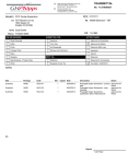
Bill of Materials
Item
Description
Qty
100GGHH
A331-2
L090-2
L164-2
L156-2
L155-2
C002-2
F182-2
R098-2
B414-2
H643-2
B184-2
A366-2
KM65-2
KD26-2
F179-2
A422-2
A333-2
E125-2
H527-2
H036-2
L028-2
F065-2
Spark Ignited Genset: 60Hz-100kW
Genset-SpkIgn NatGas/Propane,60Hz,100kW-StandbyRtg
Duty Rating-Standby Power
Listing-UL 2200
OSHPD Seismic Cert, Sds=2.28g
Cert-Seismic, IBC2000,2003,2006,Ss=3.41g.rooftop
EmissionsCert-SI,EPA,Emergency,Stationary,40CFR60
Fuel System-Natural Gas
Enclosure-Steel,Weather Protective,with ExhSys
Voltage-120/208,3 Phase,Wye,4 Wire
Alternator-60 Hz, 12 Lead, Upper Broad Range, 125C
SET CONTROL-PCC 2100
Exciter/Regulator-Pmg, 3 Phase Sensor
Engine Governor-Electronic, Isochronous Only
Circuit Breaker Mtg-Single Brkr,Left of Control
Circuit Breaker-400a,3pole,240v,Thermo-Magnetic,Ul
Skidbase-Housing Ready
Engine Starter - 12 VDC Motor
Battery Charging Alternator-Normal Output
Engine Cooling-High Ambient Air Temperature
Warning-Low Coolant Level
Coolant Heater-120 Volt Ac, Single Phase
Genset warranty- Base, Standby 2 years / 400 hours
Rack-Battery
1
1
1
1
1
1
1
1
1
1
1
1
1
1
1
1
1
1
1
1
1
1
1
start up & test
after installation
1
10 amp
battery charger
1
6
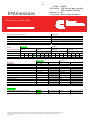
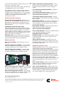
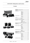
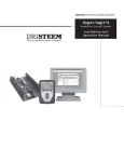
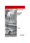
Spark-ignited generator set
85 – 100 kW standby
EPA Emissions
Description
Features
Cummins Power Generation commercial generator sets
are fully integrated power generation systems providing
optimum performance, reliability and versatility for
stationary standby and prime power applications. Codes
or standards compliance may not be available with all
model configurations – consult factory for availability.
Ford heavy-duty gas engine - Rugged 4-cycle
industrial spark-ignited delivers reliable power. The
electronic air/fuel ratio control provides optimum engine
performance and fast response to load changes.
This generator set is designed in facilities
certified to ISO 9001 and manufactured in
facilities certified to ISO 9001 or ISO 9002.
The Prototype Test Support (PTS) program
verifies the performance integrity of the
generator set design. Cummins Power
Generation products bearing the PTS symbol
meet the prototype test requirements of NFPA
110 for Level 1 systems.
All low voltage models are CSA certified to
product class 4215-01.
The generator set is available Listed to UL
2200, Stationary Engine Generator
Assemblies. The PowerCommand control is
Listed to UL 508 - Category NITW7 for U.S.
and Canadian usage.
U.S. EPA
Engine certified to U.S. EPA SI Stationary
Emission Regulation 40 CFR, Part 60.
Three-Way Catalyst – Simultaneously converts NOx,
CO and HC to nitrogen, oxygen, carbon dioxide and
water, minimizing the harmful emissions of the genset.
Alternator - Several alternator sizes offer selectable
motor starting capability with low reactance 2/3 pitch
windings, low waveform distortion with non-linear loads
and fault clearing short-circuit capability.
®
Control system - The PowerCommand electronic
control is standard equipment and provides total genset
system integration including automatic remote
starting/stopping, precise frequency and voltage
regulation, alarm and status message display,
™
AmpSentry protection, output metering, auto-shutdown
at fault detection and NFPA 110 Level 1 compliance.
Cooling system - Standard cooling package provides
reliable running at up to 40 °C (104 °F) ambient
temperature.
Enclosures - Optional weather protective and sound
attenuated enclosures are available.
NFPA - The genset accepts full rated load in a single
step in accordance with NFPA 110 for Level 1 systems.
Warranty and service - Backed by a comprehensive
warranty and worldwide distributor network.
Model
GGHG
GGHH
Natural gas
Standby rating
60 Hz
50 Hz
kW (kVA)
kW (kVA)
85 (106)
100 (125)
75 (94)
Prime rating
60 Hz
50 Hz
kW (kVA)
kW (kVA)
Propane
Standby rating
60 Hz
50 Hz
kW (kVA)
kW (kVA)
85 (106)
100 (125)
75 (94)
Prime rating
60 Hz
50 Hz
kW (kVA)
kW (kVA)
2011 Cummins Power Generation Inc. All rights reserved. Cummins Power Generation and Cummins are registered trademarks of Cummins
Inc. PowerCommand, AmpSentry, InPower and “Our energy working for you.” are trademarks of Cummins Power Generation. Other
company, product or service names may be trademarks or service marks of others. Specifications are subject to change without notice.
S-1607a (6/11)
Data sheets
60 Hz
D-3384
D-3385
50 Hz
D-3387
7
Generator set specifications
Governor regulation class
Voltage regulation, no load to full load
Random voltage variation
Frequency regulation
Random frequency variation
Radio frequency emissions compliance
ISO 8528 Part 1 Class G3
± 1.0%
± 1.0%
Isochronous
GGHH ± 0.5%, GGHG ± 0.33%
Meets requirements of most industrial and commercial applications
Engine specifications
Design
Bore
Stroke
Displacement
Cylinder block
Battery capacity
Battery charging alternator
Starting voltage
Lube oil filter type(s)
Standard cooling system
Turbocharged
90.2 mm (3.55 in)
105.9 mm (4.17 in)
3
6.8 L (412.5 in )
Cast iron, V 10 cylinder
600 amps minimum at ambient temperature of 0 °C (32 °F)
65 amps
12 volt, negative ground
Single spin-on canister-combination full flow with bypass
40 °C (104 °F) ambient radiator
Alternator specifications
Design
Stator
Rotor
Insulation system
Standard temperature rise
Exciter type
Phase rotation
Alternator cooling
AC waveform total harmonic distortion
Telephone influence factor (TIF)
Telephone harmonic factor (THF)
Brushless, 4 pole, drip proof revolving field
2/3 pitch
Direct coupled, flexible disc
Class H per NEMA MG1-1.65
150 ºC (302 °F) standby
Torque match (shunt)
A (U), B (V), C (W)
Direct drive centrifugal blower
< 5% no load to full linear load, < 3% for any single harmonic
< 50 per NEMA MG1-22.43
<3
Available voltages
60 Hz
3-phase
120/208
139/240
277/480
120/240
240/416
347/600
127/220
254/440
1-phase
120/240
50 Hz
3-phase
110/190
115/230
127/220
240/416
110/220
120/208
220/380
254/440
115/200
120/240
230/400
1-phase
110/220
120/240
Note: Consult factory for other voltages.
Generator set options and accessories
Engine
120/240 V 1500 W coolant
heaters
Fuel system
Natural gas
Natural gas/propane liquid
with automatic changeover
Natural gas/propane vapor
with automatic changeover
Propane liquid withdrawal
Vapor withdrawal
Alternator
105 C (221 °F) rise alternator
125 C (257 °F) rise alternator
150 C (302 °F) rise alternator
120/240 V, 100 W anticondensation heater
12 lead, broad range, extended
stack (full single phase output)
Lower broad range
PMG excitation
Upper broad range
Single phase (4 lead)
Exhaust system
Mounted residential muffler
Generator set
AC entrance box
Battery
Battery charger
Duct adapter
Enclosure: Aluminum, steel,
weather protection or sound
attenuated
Export box packaging
Main line circuit breaker
Note: Some options may not be available on all models - consult factory for availability.
Our energy working for you.™
www.cumminspower.com
2011 Cummins Power Generation Inc. All rights reserved. Cummins Power Generation and Cummins are registered trademarks of Cummins
Inc. PowerCommand, AmpSentry, InPower and “Our energy working for you.” are trademarks of Cummins Power Generation. Other
company, product or service names may be trademarks or service marks of others. Specifications are subject to change without notice.
S-1607a (6/11)
Remote annunciator panel
UL 2200 Listed
2 year prime power, 6000
hours, warranty
2 year standby warranty
5 year basic power warranty
5 year comprehensive
warranty
8
Control system
PowerCommand PCC2100 - An integrated generator
set control system providing isochronous governing,
voltage regulation, engine protection and operator
interface functions.
Includes integral AmpSentry protection, which provides
a full range of alternator protection functions that are
matched to the alternator provided.
Control function provides battery monitoring and
testing features, and smart starting control system.
Three phase sensing, full wave rectified voltage
regulation system, with a PWM output for stable
operation with all load types.
Standard PCCNet interface.
Suitable for operation in ambient temperatures from -40
°C to +70 °C (-40 °F to +158 °F) and altitudes to 5000
m (13,000 ft).
Prototype tested; UL, CSA and CE compliant.
InPower™ PC-based service tool available for detailed
diagnostics, setup, data logging and fault simulation.
AmpSentry AC protection
AmpSentry Protective Relay – UL-listed
Over current and short-circuit shutdown
Over current warning
Single and three phase fault regulation
Over and under voltage shutdown
Over and under frequency shutdown
Overload warning with alarm contact
Reverse power and reverse Var shutdown
Field Overload
Engine protection
Overspeed shutdown
Low oil pressure warning and shutdown
High coolant temperature warning and shutdown
High oil temperature warning (optional)
Low coolant level warning or shutdown
Low coolant temperature warning
High and low battery voltage warning
Weak battery warning
Dead battery shutdown
Fail to start (overcrank) shutdown
Fail to crank shutdown
Redundant start disconnect
Cranking lockout
Sensor failure indication
Operator interface
Off/manual/auto mode switch
Manual run/stop switch
Panel lamp/test switch
Emergency stop switch
Alpha-numeric display with pushbutton access, for
viewing engine and alternator data and providing setup,
controls and adjustments
LED lamps indicating genset running, not in auto,
common warning, common shutdown
(5) configurable LED lamps
LED bargraph AC data display (optional)
Engine Data
DC voltage
Lube oil pressure
Coolant temperature
Lube oil temperature (optional)
Other data
Genset model data
Start attempts, starts, running hours
KW hours (total and since reset)
Fault history
Load profile (hours less than 30% and hours more than
90% load)
System data display (optional with network and other
PowerCommand gensets or transfer switches)
Governing
Integrated digital electronic isochronous governor
Temperature dynamic governing
Smart idle speed mode
Glow plug control (some models)
Voltage regulation
Integrated digital electronic voltage regulator
Three phase line-to-neutral sensing
Configurable torque matching
PMG (optional)
Control functions
Data logging on faults
Fault simulation (requires InPower)
Time delay start and cooldown
Cycle cranking
(3) configurable customer inputs
(3) configurable customer outputs
Options
Analog AC Meter Display
Thermostatically Controlled Space Heater
Key-type mode switch
Ground fault module
Auxiliary relays (3)
Echelon LONWORKS interface
Modlon Gateway to convert to Modbus (loose)
PowerCommand iWatch web server for remote
monitoring and alarm notification (loose)
PCCNet and Lonworks Digital input and output
module(s) and Remote annunciators (loose)
PowerCommand 2100 control
operator/display panel
Alternator data
Line-to-line and line-to-neutral AC volts
Three phase AC current
Frequency
Total and individual phase kW and kVA
Our energy working for you.™
www.cumminspower.com
2011 Cummins Power Generation Inc. All rights reserved. Cummins Power Generation and Cummins are registered trademarks of Cummins
Inc. PowerCommand, AmpSentry, InPower and “Our energy working for you.” are trademarks of Cummins Power Generation. Other
company, product or service names may be trademarks or service marks of others. Specifications are subject to change without notice.
S-1607a (6/11)
9
Ratings definitions
Emergency standby power (ESP):
Applicable for supplying power to varying electrical load
for the duration of power interruption of a reliable utility
source. Emergency Standby Power (ESP) is in
accordance with ISO 8528. Fuel Stop power in
accordance with ISO 3046, AS 2789, DIN 6271 and BS
5514.
Limited-time running power (LTP):
Applicable for supplying power to a constant electrical
load for limited hours. Limited Time Running Power
(LTP) is in accordance with ISO 8528.
Prime power (PRP):
Applicable for supplying power to varying electrical load
for unlimited hours. Prime Power (PRP) is in accordance
with ISO 8528. Ten percent overload capability is
available in accordance with ISO 3046, AS 2789, DIN
6271 and BS 5514.
Base load (continuous) power (COP):
Applicable for supplying power continuously to a
constant electrical load for unlimited hours. Continuous
Power (COP) in accordance with ISO 8528, ISO 3046, AS
2789, DIN 6271 and BS 5514.
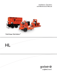
Model
GGHG
GGHH
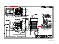
Dim “A”
mm (in.)
2662 (104.8)
2662 (104.8)
Dim “B”
mm (in.)
1016 (40.0)
1016 (40.0)
This outline drawing is for reference only. See respective model
data sheet for specific model outline drawing number.
Do not use for installation design
Dim “C”
mm (in.)
1397 (55.0)
1397 (55.0)
Set Weight*
dry kg (lbs)
1071 (2362)
1093 (2410)
Set Weight*
wet kg (lbs)
1111 (2450)
1133 (2498)
* Weights represent a set with standard features. See outline drawings for weights of other configurations.
Cummins Power Generation
rd
1400 73 Avenue N.E.
Minneapolis, MN 55432 USA
Telephone: 763 574 5000
Fax: 763 574 5298
Warning: Back feed to a utility system can cause electrocution and/or property damage. Do not connect to any building’s electrical system
except through an approved device or after building main switch is open.
Our energy working for you.™
www.cumminspower.com
2011 Cummins Power Generation Inc. All rights reserved. Cummins Power Generation and Cummins are registered trademarks of Cummins
Inc. PowerCommand, AmpSentry, InPower and “Our energy working for you.” are trademarks of Cummins Power Generation. Other
company, product or service names may be trademarks or service marks of others. Specifications are subject to change without notice.
S-1607a (6/11)
10
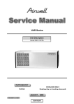
Model: GGHH
KW rating: 100 natural gas standby
100 propane standby
Frequency: 60
Fuel type: Natural gas/propane
EPA Emissions
Generator set data sheet
Exhaust emission data sheet:
Exhaust emission compliance sheet:
Sound performance data sheet:
Cooling performance data sheet:
Prototype test summary data sheet:
Standard set-mounted radiator cooling outline:
Fuel
consumption
Natural gas
Standby
kW (kVA)
Ratings
Load
scfh
m3/hr
100 (125)
1/4
1/2
406
618
11.5 17.5
EDS-327
MSP-185
PTS-147
0500-3485
Propane
Standby
kW (kVA)
100 (125)
Prime
kW (kVA)
3/4
848
24
Engine
Engine model
Configuration
Aspiration
Gross engine power output, kWm (bhp)
BMEP at rated load, kPa (psi)
Bore, mm (in)
Stroke, mm (in)
Rated speed, rpm
Piston speed, m/s (ft/min)
Compression ratio
Lube oil capacity, L (qt)
Overspeed limit, rpm
Regenerative power, kW
Full
1090
30.9
1/4
1/2
3/4
Full
1/4
178
5.1
1/2
272
7.7
Prime
kW (kVA)
3/4
367
10.4
Full
467
13.2
Natural gas
Standby rating
Prime rating
WSG-1068
Cast iron, V 10 cylinder
Turbocharged
131.3 (176.0)
1158.3 (168.0)
90.2 (3.55)
105.9 (4.17)
1800
6.4 (1250.0)
9.0:1
6.1 (6.5)
2400 ± 50
16.00
Propane
Standby rating
1.7 (7.0)
3.4 (13.6)
1.7 (7.0)
3.4 (13.6)
122.3 (164.0)
1158.3 (168.0)
90.2 (3.55)
105.9 (4.17)
1800
6.4 (1250.0)
9.0:1
6.1 (6.5)
2400 ± 50
16.00
Fuel flow
Minimum operating pressure, kPa (in H2O)
Maximum operating pressure, kPa (in H2O)
1/4
2011 Cummins Power Generation Inc. All rights reserved. Cummins Power Generation and Cummins are registered trademarks of Cummins
Inc. “Our energy working for you.” is a trademark of Cummins Power Generation. Specifications are subject to change without notice.
D-3385d (4/11)
1/2
3/4
Prime rating
Full
11
Air
Combustion air, m3/min (scfm)
Maximum air cleaner restriction, kPa (in H2O)
Alternator cooling air, m3/min (scfm)
Natural gas
Standby rating
6.3 (222.0)
1.2 (5.0)
37.0 (1308.0)
Prime rating
Propane
Standby rating
5.8 (204.0)
1.2 (5.0)
37.0 (1308.0)
Exhaust
Exhaust flow at rated load, m3/min (cfm)
Exhaust temperature, °C (°F)
Maximum back pressure, kPa (in H2O)
Available back pressure for additional sound attenuation
and piping, kPa (in H2O)
19.4 (687.0)
573 (1063)
6.2 (25.0)
17.9 (633.0)
555 (1031)
6.2 (25.0)
2.5 (10.0)
2.5 (10.0)
Standard set-mounted radiator cooling
Ambient design, °C (°F)
Fan load, kW (HP)
Coolant capacity (with radiator), L (US gal)
Coolant system air flow, m3/min (scfm)
Total heat rejection, MJ/min (Btu/min)
Maximum cooling air flow static restriction, kPa (in H2O)
40 (104)
7.3 (9.8)
33.1 (8.8)
193.1 (6825.0)
9.3 (8740.0)
124.5 (0.5)
40 (104)
7.3 (9.8)
33.0 (8.8)
193.1 (6825.0)
9.3 (8740.0)
124.5 (0.5)
Weights2
Unit dry weight kgs (lbs)
Unit wet weight kgs (lbs)
1093 (2410)
1133 (2498)
Notes:
1
2
For non-standard remote installations contact your local Cummins Power Generation representative.
Weights represent a set with standard features. See outline drawing for weights of other configurations.
Our energy working for you.™
www.cumminspower.com
2011 Cummins Power Generation Inc. All rights reserved. Cummins Power Generation and Cummins are registered trademarks of Cummins
Inc. “Our energy working for you.” is a trademark of Cummins Power Generation. Specifications are subject to change without notice.
D-3385d (4/11)
Prime rating
12
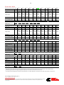
Alternator data
Natural gas three phase table
1
105 °C
105 °C
105 °C
105 °C
125 °C
125 °C
125 °C
125 °C
150 °C
150 °C
B418
B415
B268
B304
B417
B414
B267
B303
B416
B413
B419
208
110/190
thru
120/208
220/380
thru
240/416
111
208
120/208
thru
139/240
240/416
thru
277/480
111
210
120/208
thru
139/240
240/416
thru
277/480
112
207
207
120/208
thru
139/240
240/416
thru
277/480
109
209
120/208
thru
139/240
240/416
thru
277/480
111
207
206
110/190
thru
120/208
347/600
220/380
thru
240/416
110
108
207
120/208
thru
139/240
240/416
thru
277/480
109
206
110
207
110/190
thru
120/208
220/380
thru
240/416
109
Shunt
422
422
563
360
360
360
516
360
313
360
313
PMG
497
497
663
423
423
423
607
423
368
423
368
150 °C
Feature code
Alternator data sheet
b
Voltage ranges
Surge kW
Motor starting kVA (at
90% sustained voltage)
Full load current amps at
standby rating
120/208
347
Propane three phase table
1
220/380
190
240/416
173
277/480
150
347/600
120
105 °C
105 °C
105 °C
125 °C
125 °C
125 °C
125 °C
150 °C
150 °C
B415
B268
B304
B417
B414
B267
B303
B416
B413
B419
208
110/190
thru
120/208
220/380
thru
240/416
104
208
120/208
thru
139/240
240/416
thru
277/480
104
210
120/208
thru
139/240
240/416
thru
277/480
104
207
207
120/208
thru
139/240
240/416
thru
277/480
102
209
120/208
thru
139/240
240/416
thru
277/480
104
207
103
206
110/190
thru
120/208
220/380
thru
240/416
101
207
120/208
thru
139/240
240/416
thru
277/480
102
206
103
207
110/190
thru
120/208
220/380
thru
240/416
102
Shunt
422
422
563
360
360
360
516
360
313
360
313
PMG
497
497
663
423
423
423
607
423
368
423
368
120/208
347
127/220
328
139/240
301
220/380
190
347/600
240/416
173
277/480
150
347/600
347/600
120
Natural gas single phase table
105 °C
105 °C
105 °C
105 °C
125 °C
125 °C
125 °C
125 °C
Feature code
Alternator data sheet
number
Voltage ranges
B418
B415
B274
B268
B417
B414
B273
B267
120/240
120/240
120/240
120/240
120/240
120/240
120/240
120/240
Surge kW
Motor starting kVA (at
90% sustained voltage)
108
108
110
109
106
106
109
108
Full load current amps at
standby rating
208
208
2
209
2
210
3
207
3
207
2
208
2
209
3
3
Shunt
250
250
305
330
215
215
250
305
PMG
290
290
360
385
250
250
290
360
120/2402
278
120/2403
417
Propane Single phase table
105 °C
105 °C
105 °C
105 °C
125 °C
125 °C
125 °C
125 °C
Feature code
Alternator data sheet
number
Voltage ranges
B418
B415
B274
B268
B417
B414
B273
B267
208
208
209
210
207
207
208
209
120/2402
120/2402
120/2403
120/2403
120/2402
120/2402
120/2403
120/2403
Surge kW
Motor starting kVA (at
90% sustained voltage)
101
101
103
102
100
100
102
101
Full load current amps at
standby rating
Shunt
250
250
305
330
215
215
250
305
PMG
290
290
360
385
250
250
290
360
120/2402
278
120/2403
417
Notes:
1.
2.
3.
109
105 °C
Voltage ranges
Full load current amps at
standby rating
139/240
301
347/600
B418
Feature code
Alternator data sheet
b
Surge kW
Motor starting kVA (at
90% sustained voltage)
127/220
328
347/600
150 °C
Single phase power can be taken from a three phase generator set at up to 2/3 set rated 3-phase kW at 1.0 power factor. Also see Note 3 below.
The broad range alternators can supply single phase output up to 2/3 set rated 3-phase kW at 1.0 power factor.
The extended stack (full single phase output) and 4 lead alternators can supply single phase output up to full set rated 3-phase kW at 1.0 power factor.
Our energy working for you.™
www.cumminspower.com
2011 Cummins Power Generation Inc. All rights reserved. Cummins Power Generation and Cummins are registered trademarks of Cummins
Inc. “Our energy working for you.” is a trademark of Cummins Power Generation. Specifications are subject to change without notice.
D-3385d (4/11)
347/600
102
13
Derating factors
Natural gas
Standby/prime
Three phase
Standby/prime
Full single phase output
Engine power available up to 594 m (1950 ft) at ambient temperatures up to 40 °C (104 °F). Altitude
derate - 4% per 305 m (1000 ft) above 594 m (1950 ft). Temperature derate - 2% per 11 °C (1% per
10 °F) above 40 °C (104 °F).
Engine power available up to 594 m (1950 ft) at ambient temperatures up to 30 °C (86 °F). Altitude
derate - 4% per 305 m (1000 ft) above 594 m (1950 ft). Temperature derate - 4% per 10 °C (2% per
10 °F) above 30 °C (86 °F).
Propane
Standby/prime
Engine power available up to 305 m (1000 ft) at ambient temperatures up to 25 °C (77 °F). Altitude
derate - 4% per 305 m (1000 ft) above 305 m (1000 ft). Temperature derate - 2% per 11 °C (1% per
10 °F) above 25 °C (77 °F).
Ratings definitions
Emergency standby power
(ESP):
Limited-time running
power (LTP):
Prime power (PRP):
Base load (continuous)
power (COP):
Applicable for supplying power to
varying electrical load for the
duration of power interruption of a
reliable utility source. Emergency
Standby Power (ESP) is in
accordance with ISO 8528. Fuel
Stop power in accordance with
ISO 3046, AS 2789, DIN 6271 and
BS 5514.
Applicable for supplying power
to a constant electrical load for
limited hours. Limited Time
Running Power (LTP) is in
accordance with ISO 8528.
Applicable for supplying power
to varying electrical load for
unlimited hours. Prime Power
(PRP) is in accordance with ISO
8528. Ten percent overload
capability is available in
accordance with ISO 3046,
AS 2789, DIN 6271 and BS
5514.
Applicable for supplying power
continuously to a constant
electrical load for unlimited
hours. Continuous Power (COP)
is in accordance with ISO 8528,
ISO 3046, AS 2789, DIN 6271
and BS 5514.
Formulas for calculating full load currents:
Three phase output
kW x 1000
Voltage x 1.73 x 0.8
Single phase output
kW x SinglePhaseFactor x 1000
Voltage
Cummins Power Generation
1400 73rd Avenue N.E.
Minneapolis, MN 55432 USA
Phone: 763 574 5000
Fax: 763 574 5298
Warning: Back feed to a utility system can cause electrocution and/or property damage. Do not connect to any building’s electrical system
except through an approved device or after building main switch is open.
Our energy working for you.™
www.cumminspower.com
2011 Cummins Power Generation Inc. All rights reserved. Cummins Power Generation and Cummins are registered trademarks of Cummins
Inc. “Our energy working for you.” is a trademark of Cummins Power Generation. Specifications are subject to change without notice.
D-3385d (4/11)
14
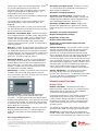
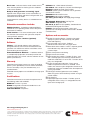
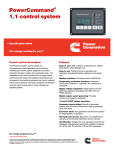
PowerCommand® 2100
digital generator set
control
Description
Features
®
The PowerCommand 2100 Control is a microprocessorbased generator set monitoring, metering and control
system. The control provides an operator interface to the
genset, digital voltage regulation, digital governing and
generator set protective functions. The integration of all
the functions into a single control system provides
enhanced reliability and performance compared to
conventional control systems.
The PowerCommand control is designed for mounting on
the generator set and is suitable for use on a wide range of
generator sets in non-paralleling applications. The
PowerCommand Control will directly read AC voltages up
to 600 VAC and can be configured for any frequency,
voltage and power connection configuration from 120 to
600 VAC.
The control offers a wide range of standard control and
digital display features so custom control configurations
are not needed to meet application specifications. System
reliability is not compromised by use of untested special
components.
Power for PowerCommand Control is usually derived from
the generator set starting batteries. It functions without
degradation in performance over a voltage range from 8
VDC to 35 VDC.
Digital engine speed governing controls - Provide
isochronous frequency regulation (optional on some
genset models).
Digital voltage regulation – 3-phase sensing.
AmpSentry™ protective relay – UL Listed, true
alternator over current protection.
Analog and digital AC output metering.
Battery monitoring system - Senses and warns
against a weak battery condition.
Digital alarm and status message display.
Generator set monitoring - Displays status of all
critical engine and alternator functions.
Smart starting control system - Temperature dynamic
integrated fuel ramping to limit black smoke and frequency
overshoot, in addition to optimized cold weather starting.
PCCNet Interface - A proprietary RS485 network
interface to allow easy plug and play interface to remote
annunciators, relay modules for extensible I/O and other
devices.
Advanced serviceability - Interfaces to InPower™, a
PC-based software service tool. A version of InPower is
available for customer use.
®
PowerCommand LonWorks network (optional) Provides interfaces to external devices through a twisted
pair wire and other media.
Certifications - Suitable for use on generator sets that
are designed, manufactured, tested, and certified to
relevant UL, NFPA, ISO, IEC, and CSA standards.
Warranty and service - Backed by a comprehensive
warranty and worldwide distributor service network.
2008_Cummins Power Generation Inc._All rights reserved_Specifications subject to change without notice_Cummins Power Generation
and Cummins are registered trademarks of Cummins Inc. PowerCommand, InPower, AmpSentry and “Our energy working for you.” are
trademarks of Cummins Power Generation. Other company, product, or service names may be trademarks or service marks of others.
S-1409g (4/08) Page 1 of 8
15
Operator panel
The operator panel provides the user with a complete
package of easy to view and use information. Connections
to the operator panel are locking plug interfaces for
reliable, vibration-resistant interconnection to the
generator set wiring harness.
Control switches and functions
Off/manual/auto mode control switch - The not in
auto lamp will flash when the control is in the manual or off
mode. In the auto mode, the generator set can be started
with a start signal from a remote device, such as an
automatic transfer switch.
Manual run/stop control switch - When the mode
control switch is in the manual position and the
manual/run/stop switch is pressed, the generator set will
start, bypassing time delay start. The control is
configurable to include an idle period on manual start. If
the generator set is running in the manual mode, pressing
the run/stop switch will cause the generator set to shut
down after a cool down at idle period.
The operator panel includes a series of LED indicating
lamps to allow the operator to view the general status of
the generator set. Functions displayed include:
Green lamps to indicate generator set running (operating
at rated voltage and frequency); remote start signal
received.
Red (flashing) lamp to indicate not-in-auto mode and a
red lamp to indicate common shutdown.
Amber lamp for common warning.
Lamps (5) are configurable for color and function. These
lamps are configured with InPower for any condition
monitored by the control. Default configuration for these
lamps include the following functions:
- Low oil pressure warning
- High engine temperature warning
- Low oil pressure shutdown
- Over speed shutdown
- Fail to start
Analog AC metering panel (optional)
Panel lamp/lamp test control switch - Depressing
the panel lamp switch will cause the panel illumination to
operate for approximately 10 minutes. Pressing and
holding the switch will sequentially illuminate all LED lamps
on the panel to confirm proper operation of these
components.
Fault acknowledge/reset switch - The control
includes a fault acknowledge function to allow the operator
to reset the fault condition. If the fault condition is not
corrected, the fault will reappear, but will not be logged as
a separate event. Multiple faults can be logged and
displayed at one time.
Emergency stop control switch - Pressing the
emergency stop switch will cause the generator set to
immediately shut down. The generator set is prevented
from running or cranking with the switch pressed in.
Operator adjustments - The control includes provisions
for many set up and adjustment functions via raise/lower
switches on the operator panel. Functions that can be
adjusted by the operator include:
- Time delay start (0-300 seconds)
- Time delay stop (0-600 seconds)
- Alternator voltage (+5%)
- Alternator frequency (+5%)
The PowerCommand control can be equipped with an
analog AC metering panel that simultaneously displays 3phase line-to-line AC volts and current, kW, power factor,
and frequency.
The meter panel is composed of a series of LEDs
configured in bar graphs for each function. The LEDs are
color coded, with green indicating normal range values,
amber for warning levels and red for shutdown conditions.
Scales for each function are in % of nominal rated values.
Resolution is 1% for values close to nominal and increases
at values far from nominal.
Alphanumeric display panel
Indicating lamps
The PowerCommand control is provided with an
alphanumeric display capable of displaying 2 lines of data
with approximately 20 characters per line. The display is
accompanied by a set of six tactile-feel membrane
switches that are used by the operator to navigate through
Our energy working for you.™
www.cumminspower.com
2008_Cummins Power Generation Inc._All rights reserved_Specifications subject to change without notice_Cummins Power Generation
and Cummins are registered trademarks of Cummins Inc. PowerCommand, InPower, AmpSentry and “Our energy working for you.” are
trademarks of Cummins Power Generation. Other company, product, or service names may be trademarks or service marks of others.
S-1409g (4/08) Page 2 of 8
16
control menus and to make control adjustments. (There
are no rotary potentiometers in the control. All
adjustments are made via the display panel or InPower).
Display is configurable for multiple languages. It is
configurable for units of measurement.
All data on the control can be viewed by scrolling through
screens with the navigation keys.
The control displays all active fault conditions with the
latest displayed first. Active and inactive faults are
displayed.
The display panel includes a screen-saver timer that will
turn off the display after 30 minutes of inactivity. Touching
any key will turn the screen back on.
Generator set hardware data - Generator set rating in
kVA, complete generator set model number and provisions
for generator set serial number, engine model and serial
number, and alternator model and serial number. The
control stores the part number of the control and the
software version present in the control. This information is
read using InPower.
Data logs - Number of start attempts and number of start
attempts since reset. Number of times generator set has
run and duration of generator set running time. Generator
set kWh produced. The control also stores number of start
attempts, operating hours and kW hours since each has
been reset. This data is read with InPower.
Adjustment history - Provides a record of adjustment
and setting changes made on the control and identifies
whether adjustment was made via the operator panel or
with a service tool. If a service tool is used, the control
provides a record of the serial number of the tool used.
This information is read with InPower.
Fault history - Provides a record of the most recent fault
conditions with time stamp, along with the number of
times each fault has occurred. Up to 20 events are stored
in the control non-volatile memory.
Generator set output current - All phases, accuracy
1%. Data for all phases is displayed simultaneously to
allow viewing of load balance.
Generator set output frequency.
Generator set power output - PowerCommand
displays generator set kW and kVA output (average and
individual phase and direction of flow), and power factor
with leading/lagging indication. Accuracy 5%.
Generator set kWh power output - Displays total
kilowatt-hours produced by the generator set and total
produced since last reset, with time stamp of time of last
reset.
Generator set control temperature.
Engine starting battery voltage.
Engine lube oil pressure.
Engine coolant temperature.
Engine lube oil temperature (option on some
genset models).
System data display - The generator set will exchange
data with Cummins Power Generation transfer switches
utilizing PowerCommand transfer controls and other
generator sets using the PowerCommand 2100 control
that are located on the same site and interconnected using
a PowerCommand network. Information displayed from
each transfer switch in the system includes: transfer switch
name (assigned by customer at site), kW load (when fitted
with load monitoring equipment), sources available, source
connected and if any alarm conditions are present on the
switch. Genset data includes genset name, kW load,
status and name of any alarm conditions that are present.
Service adjustments - The operator panel includes
provisions for adjustment and set up of all control
functions in the generator set. The operator panel includes
an access code that is used to protect the control from
unauthorized service level adjustments.
Internal control functions
Engine control
Remote start mode - PowerCommand accepts a
ground signal from remote devices or a network signal to
automatically start the generator set and immediately
accelerate to rated speed and voltage.
Load profile data - Control logs data indicating the
operating hours at percent of rated kW load in 10%
increments. The data is presented on the operator panel
based on total operating hours on the generator set based
on number of hours under 30% load and number of hours
at more than 90% of rated. InPower can be used to read
data in detail (10% increments).
Generator set output voltage - All phases, line-to-line
and line-to-neutral, accuracy 1%. Data for all phases is
displayed simultaneously to allow viewing of voltage
balance.
PowerCommand includes a smart starting system that is
designed to quickly start the engine, minimize black
smoke, minimize voltage and frequency overshoot, and
oscillations on starting. The control system does this by
careful control of the engine fuel system and alternator
excitation system.
The control can incorporate a time delay start and a warmup period at idle speed. See Engine governing for details.
Sleep mode - PowerCommand can be configured to
include a sleep mode. When enabled, and when the mode
select switch is in the off position, the control will revert to
Our energy working for you.™
www.cumminspower.com
2008_Cummins Power Generation Inc._All rights reserved_Specifications subject to change without notice_Cummins Power Generation
and Cummins are registered trademarks of Cummins Inc. PowerCommand, InPower, AmpSentry and “Our energy working for you.” are
trademarks of Cummins Power Generation. Other company, product, or service names may be trademarks or service marks of others.
S-1409g (4/08) Page 3 of 8
17
a low power consumption mode until a control switch on
the operator panel is operated (reset, panel lamp, manual
run or emergency stop).
Data logging - The control maintains a record of manual
control operations, warning and shutdown conditions, and
other events. The control also stores critical engine and
alternator data before and after a fault occurs, for use by
InPower and the technician in evaluating the root causes
for the fault condition.
Fault simulation mode - PowerCommand, in
conjunction with InPower software, will accept commands
to allow a technician to verify the proper operation of all
protective functions of the control by simulating failure
modes or by forcing the control to operate outside of its
normal operating ranges.
Engine starting - The control system automatically
controls the engine starter and provides proper engine
fueling and alternator control to provide fast and efficient
starting.
Cycle cranking - Configurable for number of starting
cycles (1 to 7) and duration of crank and rest periods.
Control includes starter protection algorithms to prevent
the operator from specifying a starting sequence that
might be damaging.
Time delay start and stop (cool down) - Configurable
for time delay of 0-300 seconds prior to starting after
receiving a remote start signal; and for time delay of 0-600
seconds prior to ramp-to-idle or shutdown after signal to
stop in normal operation modes. Default for both time
delay periods is 0 seconds.
Engine governing
The PowerCommand control includes integrated digital
governing capability to directly drive an engine fuel control
valve. Features of the governing system (when enabled)
include:
Isochronous governing - Controls engine speed within
+0.25% for any steady state load from no load to full load.
Frequency drift will not exceed +0.5% for a 33 °C (60 °F)
change in ambient temperature over an 8 hour period.
Temperature dynamics - Modifies the engine fuel
system (governing) control parameters as a function of
engine temperature. Allows engine to be more responsive
when warm and more stable when operating at lower
temperature levels.
Smart idle mode - Engine governing can be regulated at
an idle speed for a programmed period on automatic stop
of the engine or in manual mode. In an automatic mode,
the control will bypass the idle period if the engine is at a
low load level for sufficient duration for cool down. During
idle mode engine protective functions are adjusted for the
lower engine speed, and alternator function and
protections are disabled.
Idle speed can be initiated by the operator when the
generator set is running in the manual mode.
Glow plug control (optional) - Modifies the engine start
cycle to include a programmed time period for operation of
glow plugs. This feature is available on generator sets that
require glow plug control only.
Alternator control
PowerCommand includes an integrated 3-phase line-toneutral sensing voltage regulation system that is
compatible with either shunt or PMG type excitation
systems (some generator set models are always PMG).
The voltage regulation system is full wave rectified and has
a PWM output for good motor starting capability and
stability when powering non-linear loads. Major system
features include:
Digital output voltage regulation - PowerCommand
will regulate output voltage to within 0.5% for any loads
between no load and full load. Voltage drift will not exceed
+0.5% for a 33 °C (60 °F) change in temperature in an 8
hour period. On engine starting, or sudden load
acceptance, voltage is controlled to a maximum of 5%
overshoot over nominal level.
Torque-matched V/Hz overload control - The voltage
roll-off set point and rate of decay (i.e., the slope of the
V/Hz curve) is adjustable in the control.
Fault current regulation - PowerCommand will
regulate the output current on any phase to a maximum of
3 times rated current under fault conditions for both single
phase and three phase faults. The regulation system will
drive a permanent magnet generator (PMG) to provide 3
times rated current on all phases for motor starting and
short circuit coordination purposes.
Protective functions
On a warning condition the control will indicate a fault by
lighting the warning LED on the control panel and
displaying the fault name and code on the operator display
panel. The nature of the fault and time of occurrence are
logged in the control. The service manual and InPower
service tool provide service keys and procedures based on
the service codes provided.
On a shutdown condition, the control will light the
shutdown LED on the control panel, display the fault name
and code, initiate shutdown and lock out the generator set.
The control maintains a data log of all fault conditions as
they occur and time stamps them with the controller run
time and engine operating hours data. Adjustments to
most set points are made using the InPower service tool.
The control system includes a “fault bypass” mode that
may be enabled by a service technician. The fault bypass
mode forces the system to function regardless of the
status of protective functions. (Each function must be
individually bypassed.) In this mode the only protective
functions that are operational are over speed, loss of
speed sensor, moving the control switch to the off position
or pressing the emergency stop switch. The control
maintains a record of the time that the mode is enabled,
Our energy working for you.™
www.cumminspower.com
2008_Cummins Power Generation Inc._All rights reserved_Specifications subject to change without notice_Cummins Power Generation
and Cummins are registered trademarks of Cummins Inc. PowerCommand, InPower, AmpSentry and “Our energy working for you.” are
trademarks of Cummins Power Generation. Other company, product, or service names may be trademarks or service marks of others.
S-1409g (4/08) Page 4 of 8
18
and all warning or shutdown conditions that have occurred
while in the “fault bypass” mode.
The control system automatically captures the generator
set logged parameters on a fault condition.
Many protective functions within the control system are
configurable for warning, shutdown or both (2 levels).
Exceptions to this include functions such as over speed
conditions and loss of speed sensing. In addition, some
functions can incorporate control functions as a
consequence of a fault.
System protective functions:
Ground fault warning (optional) - 600 VAC class
generator sets with solid ground. Ground fault sensing is
adjustable over a range of 100-1200 amps with time
delays of 0-1 second. May be configured for shutdown
rather than alarm.
Configurable alarm and status inputs PowerCommand will accept up to four alarm or status
inputs (configurable contact closed to ground or open) to
indicate customer-specified conditions. The control is
programmable for warning, shutdown or status indication,
and for labeling the input. Eight additional faults can be
input to the control via the network.
Emergency stop - Annunciated whenever the local or
remote emergency stop signal is received. Alarm panel
distinguishes between local or remote operation.
Engine protection
Over speed shutdown - Default setting is 115% of
nominal.
Low lube oil pressure shutdown - Level is preset to
match the capabilities of each engine. Control includes
time delays to prevent nuisance shutdown signals.
Low lube oil pressure warning - Level is preset to
match the capabilities of each engine. Control includes
time delays to prevent nuisance shutdown signals.
High oil temperature warning (optional) - Level is
preset to match the capabilities of each engine. Control
includes time delays to prevent nuisance shutdown
signals.
Low coolant level warning/shutdown - Optional on
some genset models.
Low coolant temperature warning - Indicates that
engine temperature may not be high enough for a 10second start or proper load pickup.
Low and high battery voltage warning - Indicates
battery charging system failure by continuously monitoring
battery voltage.
Weak battery warning - The control system will test the
battery bank each time the generator set is signaled to
start, and indicate a warning if the generator set battery
indicates impending failure.
Dead battery shutdown - Indicates that generator set
failed to start due to failed starting battery.
Fail to start (overcrank) shutdown.
Fail to crank shutdown - Control has signaled starter to
crank engine but engine does not rotate.
Redundant starter disconnect.
Cranking lockout - The control will not allow the starter
to attempt to engage or to crank the engine when the
engine is rotating.
Sensor failure indication - All analog sensors are
provided with sensor failure logic to indicate if the sensor
or interconnecting wiring has failed. Separate indication is
provided for fail high or low.
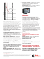
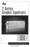
AmpSentry protective relay
AmpSentry protective relay is a UL Listed comprehensive
monitoring and control system integral to the
PowerCommand Control System that guards the electrical
integrity of the alternator and power system by providing
protection against a wide array of fault conditions in the
generator set or in the load. It also provides single and
three phase fault current regulation so that downstream
protective devices have the maximum current available to
quickly clear fault conditions without subjecting the
alternator to potentially catastrophic failure conditions. See
document R1053 below for a full size time over current
curve.
Over current warning - Output current on any phase at
more than 110% of rating for more than 60 seconds or
more than 400% for more than 1 second.
High coolant temperature shutdown - Level is preset
to match the capabilities of each engine. Control includes
time delays to prevent nuisance shutdown signals.
High coolant temperature warning - Level is preset
to match the capabilities of each engine. Control includes
time delays to prevent nuisance shutdown signals.
Over current shutdown (51) - Output current on any
phase is more than 110%, less than 175% of rating and
approaching thermal damage point of alternator. Control
includes algorithms to protect alternator from repeated
over current conditions over a short period of time.
Our energy working for you.™
www.cumminspower.com
2008_Cummins Power Generation Inc._All rights reserved_Specifications subject to change without notice_Cummins Power Generation
and Cummins are registered trademarks of Cummins Inc. PowerCommand, InPower, AmpSentry and “Our energy working for you.” are
trademarks of Cummins Power Generation. Other company, product, or service names may be trademarks or service marks of others.
S-1409g (4/08) Page 5 of 8
19
Reverse Var shutdown - Shutdown level is adjustable:
threshold 0.15-0.50 per unit, delay 10-60 seconds.
Defaults: 0.20, 10 seconds.
Excitation fault - Shutdown of generator set will occur
on loss of voltage sensing inputs to control.
ALTERNATOR THERMAL
DAMAGE CURVE
10
AMPSENTRY
PROTECTION
1
Environment
0.1
0.05
1
3
10
AMPS (TIMES RATED)
100
Short circuit shutdown - Output current on any phase
is more than 110%, more than 175% of rating, and
approaching thermal damage point of alternator. Control
includes algorithms to protect alternator from repeated
over current conditions over a short period of time.
High AC voltage shutdown (59) - Output voltage on
any phase exceeds preset values. Time to trip is inversely
proportional to amount above threshold. Values
adjustable from 105-125% of nominal voltage with time
delay adjustable from 0.25-10 seconds. Default value is
110% for 10 seconds.
Low AC voltage shutdown (27) - Voltage on any phase
has dropped below a preset value. Adjustable over a
range of 50-95% of reference voltage, time delay 2-10
seconds. Default value is 85% for 10 seconds. Function
tracks reference voltage.
The control is designed for proper operation without
recalibration in ambient temperatures from -40 °C to
+70 °C (-40 °F to +158 °F), and for storage from 55 °C to
+80 °C (-67 °F to +176 °F). Control will operate with
humidity up to 95%, non-condensing. Control operation is
not restricted by altitude.
The control system is housed in a NEMA 3R/IP53
enclosure. The operator control panel has a single
membrane surface which is impervious to the effects of
dust, moisture, oil and exhaust fumes. The panel uses
sealed membrane or oil-tight switches to provide long
reliable service life in harsh environments.
The control system is specifically designed and tested for
resistance to RFI/EMI and to resist the effects of vibration
to provide a long reliable life when mounted on a generator
set. The control includes transient voltage surge
suppression to provide compliance to referenced
standards.
Control interface
Input signals to the PowerCommand control
include:
Under frequency shutdown (81u) - Generator set
output frequency cannot be maintained. Settings are
adjustable from 0-10 Hz below nominal governor set point
for a 0-20 second time delay. Default: 6 Hz, 10 seconds.
Remote start signal - May be connected via either
discrete signal or Lon™ Network, or both.
Over frequency shutdown/warning (81o) Adjustable for operation in a range of 0-10 Hz above
nominal frequency, with a time delay of 0-20 seconds.
Defaults: Disabled.
Remote alarm reset.
Over load (kW) warning - Provides a warning indication
when engine is operating at a load level over a set point or
due to under frequency. Adjustment range: 50-140% of
rated kW, 0-120 second delay. Defaults: 105%, 60
seconds.
Reverse power shutdown (32) - Adjustment range: 520% of standby kW rating, delay 1-15 seconds. Defaults:
10%, 3 seconds.
Remote emergency stop.
Configurable customer inputs - Control includes (4)
input signals from customer discrete devices that are
configurable for warning, shutdown or status indication, as
well as message displayed.
Output signals from the control include four
configurable relay drivers. Defaults for these
are:
Generator set common warning signal - Operates
when unit set is running under alarm conditions.
Generator set common shutdown signal.
Our energy working for you.™
www.cumminspower.com
2008_Cummins Power Generation Inc._All rights reserved_Specifications subject to change without notice_Cummins Power Generation
and Cummins are registered trademarks of Cummins Inc. PowerCommand, InPower, AmpSentry and “Our energy working for you.” are
trademarks of Cummins Power Generation. Other company, product, or service names may be trademarks or service marks of others.
S-1409g (4/08) Page 6 of 8
20
Not in auto - Indicates that the mode control switch is
not in the auto position or that the genset is shutdown
under a fault condition.
Ready to load (generator set running) signal Operates when the generator set has reached 90% of
rated speed and voltage and latches until generator set is
switched to off or idle mode.
Control power for auxiliary devices is available from the
controller.
Network connections include:
PCCNet interface - A proprietary dedicated RS485
network for use in operating remote annunciator panels
and remote I/O modules.
Serial interface - This communication port is to allow
the control to communicate with a personal computer
running InPower software.
®
®
Echelon LonWorks interface (optional).
Software
InPower - A PC-based software service tool that is
designed to directly communicate to PowerCommand
generator sets and transfer switches to facilitate service
and monitoring of these products.
PowerCommand for Windows® - A software tool that
is used primarily by operators to remotely monitor and
control generator sets, transfer switches and other on-site
power system devices.
Warranty
PowerCommand control systems are a part of complete
power systems provided by Cummins Power Generation,
and are covered by a one-year limited warranty as a
standard feature.
Extended warranty options are available for coverage up to
10 years.
Certifications
PowerCommand meets or exceeds the requirements of
the following codes and standards:
CSA 22.2: No. 14 M91 Industrial Controls
ISO 8528-4: 1993 compliance, Controls and Switchgear
NFPA99: Standard for Health Care Facilities
CE Mark: Control system suitable for use on generator
sets to be CE-marked
EN 50081-2: Industrial Emissions
EN 50082-2: Industrial Susceptibility
ISO 7637, pulses #2b, 4: DC Supply Surge Voltage
Test
Mil Std 202C, Method 101: Salt Fog Test
ANSI C62.41: Surge Withstand
IEC 801.2, 3, 4, 5: For Susceptibility, Conducted and
Radiated Electromagnetic Emissions.
ISO9001: PowerCommand control systems and
generator sets are designed and manufactured in ISO9001
certified facilities.
Options and accessories
Analog AC metering display - Provides a bar graph
display of 3-phase AC volts and amps, kW, power
factor and frequency.
Key-type mode select switch - Replaces
off/manual/auto switch with a key-type switch.
Ground fault alarm module - Installs a separate ground
fault indication relay and harness into a control
customer input.
Exhaust temperature monitoring.
Digital remote annunciator.
Digital output relay module - Provides (3) relays, each
with 2 normally open and 2 normally closed contacts
rated 10 A at 600 VAC, 5 A at 24 VDC. Functions of the
relays are configurable.
Engine oil temperature indication - Some genset
models incorporate this feature as standard. On all
models, the control may be configured to include an oil
temperature warning or shutdown when oil temperature
sensing is provided.
CAN engine interface (optional on some models).
Allows the genset control to directly monitor an engine
control module.
LON interface.
Input/output expansion module – Provides up to 16
configurable Form-C relays, 12 configurable discrete
inputs and 8 analog inputs.
NFPA110: For Level 1 systems
UL508: Recognized or Listed and suitable for use on
UL 2200 Listed generator sets
CSA C282-M1999: Compliance
Our energy working for you.™
www.cumminspower.com
2008_Cummins Power Generation Inc._All rights reserved_Specifications subject to change without notice_Cummins Power Generation
and Cummins are registered trademarks of Cummins Inc. PowerCommand, InPower, AmpSentry and “Our energy working for you.” are
trademarks of Cummins Power Generation. Other company, product, or service names may be trademarks or service marks of others.
S-1409g (4/08) Page 7 of 8
21
See your distributor for more information
Cummins Power Generation
Americas
rd
1400 73 Avenue N.E.
Minneapolis, MN 55432 USA
Phone: 763 574 5000
Fax: 763 574 5298
Europe, CIS, Middle East and Africa
Manston Park Columbus Ave.
Manston Ramsgate
Kent CT 12 5BF United Kingdom
Phone 44 1843 255000
Fax 44 1843 255902
Asia Pacific
10 Toh Guan Road #07-01
TT International Tradepark
Singapore 608838
Phone 65 6417 2388
Fax 65 6417 2399
Warning: Back feed to a utility system can cause electrocution and/or property damage. Do not connect to any building electrical except
through an approved device or after building main breaker is open.
2008_Cummins Power Generation Inc._All rights reserved_Specifications subject to change without notice_Cummins Power Generation
and Cummins are registered trademarks of Cummins Inc. PowerCommand, InPower, AmpSentry and “Our energy working for you.” are
trademarks of Cummins Power Generation. Other company, product, or service names may be trademarks or service marks of others.
S-1409g (4/08) Page 1 of 8
22
Frame Size:
ALTERNATOR DATA SHEET
UC3D
CHARACTERISTICS
WEIGHTS:
Wound Stator Assembly
Rotor Assembly
Complete Alternator
265 lb
317 lb
941 lb
Full Load
2 Amps
Class H Throughout
EXCITATION CURRENT:
INSULATION SYSTEM:
(Based on specified temperature rise
at 40°C ambient temperature)
125°C Rise Ratings
105°C Rise Ratings
kW/kVA
kW/kVA
(0.8 power factor)
3 Ø RATINGS
(Based on specified temperature rise
at 40°C ambient temperature)
150°C Rise Ratings
125°C Rise Ratings
105°C Rise Ratings
80°C Rise Ratings
3 Ø REACTANCES
No Load
0.5 Amps
2250 rpm
MAXIMUM SPEED:
60 Hz
(1.0 power factor)
1 Ø RATINGS
120 kg
144 kg
427 kg
50 Hz
Double Delta
4 Lead
Double Delta
120/240
120/240
110-120
220-240
79 / 79
72 / 72
90 / 90
81 / 81
68 / 68
60 / 60
Upper Broad Range
LBR*
347/600
Broad Range
120/208
139/240
190-208
110/190
120/208
127/220
240/416
277/480
380-416
347/600
220/380
240/415
254/440
kW
kVA
kW
kVA
110
138
105
131
124
155
117
146
110
138
105
131
124
155
117
146
97
121
91
114
97
121
91
114
92
116
87
109
kW
kVA
kW
kVA
96
120
105
131
96
120
105
131
80
100
80
100
74
93
80
100
88
110
80
100
88
110
72
90
72
90
67
84
2.53
0.21
0.14
0.17
0.10
2.08
0.17
0.12
0.14
0.08
2.00
0.16
0.12
0.14
0.08
1.82
0.16
0.12
0.14
0.08
2.11
0.18
0.13
0.14
0.08
1.77
0.15
0.11
0.11
0.07
1.46
0.12
0.09
0.09
0.06
(per unit, ±10%)
(Based on full load at 105°C Rise Rating)
Synchronous
Transient
Subtransient
Negative Sequence
Zero Sequence
3 Ø MOTOR STARTING
(Shunt)
360
360
360
(90% Sustained Voltage)
(PMG)
423
423
423
244
306
TIME CONSTANTS
(Sec)
0.030
0.010
0.820
0.007
0.030
0.010
0.820
0.007
0.030
0.010
0.820
0.007
0.030
0.010
0.820
0.007
0.0900
1.2000
12
0.0680
1.2000
12
0.1250
1.2000
6
0.0900
1.2000
12
Maximum kVA
Transient
Subtransient
Open circuit
DC
WINDINGS
Stator Resistance
Rotor Resistance
Number of Leads
(@ 20°C )
(Line to Line, Ohms)
( Ohms)
* Lower broad range 110/190 thru 120/208, 220/380 thru 240/416.
Specification May change WIthout Notice.
Cummins Power Generation
ADS - 207D
23
Prototype Test Supported
Emergency/Standby Generator Sets
Certification
Cummins Power Generation certifies that its commercial generator sets bearing the Prototype Test Supported
(PTS) seal have been subjected to a design and development process that includes extensive prototype testing
and evaluation. A PTS production model is engineered and manufactured according to documentation
developed through comprehensive research, design and design verification.
Design verification is based on tests of preproduction prototype models manufactured specifically for
prototype test purposes and not sold as new equipment. To be certified as a PTS model, the generator set
must satisfy these prerequisites:
DESIGN - The PTS certified generator set must be designed specifically for emergency/standby applications
that require high reliability and rapid response.
PROTOYPE TESTING - Design suitability of the PTS certified generator set must be proven by tests on
preproduction prototype models. The prototype test program is intended to:
1. Confirm the engine and generator have reserve capacity beyond rating to minimize the potential of
damage or shutdown during steady state or transient loading conditions, including momentary
overloads.
2. Demonstrate generator set, controls and accessories capability to perform reliably and compatibly in
service during disturbances common in actual load circuits.
3. Verify the integrity of the generator and excitation system insulation systems and electrical components
to withstand heating under rated load and transient overcurrent conditions.
4. Evaluate generator set mechanical and electrical strength to perform without damage during abnormal
operating conditions, such as short circuits or out-of-phase paralleling. While operating at rated load,
the generator set must be subjected to several 3-phase short circuits of 20 second duration. After the
tests, the generator set is inspected to verify that no electrical or mechanical damage was incurred by
any components.
5. Determine by endurance testing that no resonance conditions exist in the generator set or accessories
that will cause premature failure of components on production units.
6. Investigate and identify failure modes to minimize the risk of any single component failure or human error
that could lead to lack of essential electrical supply.
7. Provide a margin of safety, by actual trials, between the generator set component design and protection
systems so that the components are not damaged before the protective devices activate a shutdown.
DOCUMENTATION AND SOFTWARE - The PTS certified generator set must be documented in a single
drawing package with all components identified with Cummins Power Generation part numbers. A PTS test
certificate must be created for each PTS generator set certifying the PTS testing performed.
QUALITY ASSURANCE - Engineering drawings, specifications and test requirements for a PTS certified
generator set must be classified by components and assembly quality characteristics. A component and
process inspection and test plan must be developed and maintained to measure product conformance to
documentation requirements.
PRODUCTION MODEL TESTING - PTS certified generator sets must be subjected to complete production
tests that demonstrate conformance to specifications at all rated conditions, including start-up, full load pickup
and a performance run at full rated load and power factor.
1/2007 Bulletin F-927
24
PROTOTYPE TEST SUPPORT (PTS)
60 HZ TEST SUMMARY
GENERATOR SET MODELS
85GGHG
100GGHH
REPRESENTATIVE PROTOTYPE
Model:
100GGHH
Engine:
WSG-1068
Alternator: UC3D
The following summarizes prototype testing conducted on the designated representative prototype of the specified
models. This testing is conducted to verify the complete generator set electrical and mechanical design integrity.
Prototype testing is conducted only on generator sets not sold as new equipment.
Maximum Surge Power:
110 KW
Steady State Performance:
The generator set was evaluated to determine the stated
maximum surge power.
Maximum Motor Starting: 360 KVA
The generator set was tested to simulate motor starting
by applying the specified kVA load at low lagging power
factor (0.4 or lower). With this load applied, the generator
set recovered to a minimum of 90% rated voltage
The generator set was tested to verify steady state
operating performance was within the specified maximum
limits.
Voltage Regulation:
Random Voltage Variation:
Frequency Regulation:
Random Frequency Variation:
±0.50%
±0.50%
Isochronous
±0.50%
Transient Performance:
Torsional Analysis and Testing:
The generator set was tested to verify that the design is
not subjected to harmful torsional stresses in excess of
5000psi. A spectrum analysis of the transducer output
was conducted over the
1200 to 2000 RPM.
speed range of
40 °C Ambient
0.50 in. H2O restriction
The cooling system was tested to determine ambient
temperature and static restriction capabilities. The test
was performed at full rated load in elevated ambient
temperature under stated static restriction conditions.
Cooling System:
Durability:
The generator set was subjected to a minimum 500
hour endurance test operating at variable load up to the
standby rating based upon MIL-STD-705 to verify
structural soundness and durability of the design.
The generator set was tested with the standard alternator
to verify single step loading capability as required by
NFPA 110. Verify acceptable Voltage and frequency
response on load addition or rejection were evaluated.
The following results were recorded for Natural Gas:
Full Load Acceptance:
Voltage Dip:
Recovery Time:
Frequency Dip:
Recovery Time:
Full Load Rejection:
Voltage Rise:
Recovery Time:
Frequency Rise:
Recovery Time:
39.2
7.5
15.3
8.1
%
Second
%
Second
18.6
1.0
13.1
2.5
%
Second
%
Second
Harmonic Analysis:
(per MIL-STD-705B, Method 601.4)
Line to Line
Line to Neutral
Electrical and Mechanical Strength:
Harmonic
The generator set was tested to several single phase and
three phase faults to verify that the generator can safely
withstand the forces associated with short circuit
conditions. The generator set was capable of producing
full rated output at the conclusion of the testing.
Cummins Power Generation
3
5
7
9
11
13
15
No Load
Full Load
No Load
Full Load
0.056
0.74
0.72
0.00
0.375
0.12
0.00
0.184
0.79
2.05
0.03
0.64
0.53
0.00
0.00
0.72
0.72
0.00
0.37
0.115
0.00
0.14
0.76
2.00
0.00
0.62
0.53
0.00
Specification May Change Without Notice
pts-147c
400 amp circuit
breaker and stub
up location
25
Drawing Name: 0500-4087 Revision: L
Part Name: 0500-4087 Revision: L
Sheet 1 of 10
26
Drawing Name: 0500-4087 Revision: L
Part Name: 0500-4087 Revision: L
Sheet 8 of 10
27
Sheet 1 of 4
28
Sheet 2 of 4
29
Sheet 3 of 4
30
Drawing Name: 0500-4087 Revision: L
Part Name: 0500-4087 Revision: L
Sheet 3 of 10
31
/3(
*OUFMMJHFOU&OHJOF4UBSU#BUUFSZ$IBSHFS
5IF4NBSU$IPJDFGPS.JTTJPO$SJUJDBM&OHJOF4UBSUJOH
t 'BTUBDDVSBUFNJTTJPODSJUJDBMDIBSHJOHoHJWFTCFTUTUBSUJOHSFMJBCJMJUZ
t 3FQMBDFOFBSMZBOZDIBSHFSoXJUIPVUQMBOOJOHBIFBE
t *OEVTUSZmSTUCBUUFSZGBVMUBMBSNIFMQTEJTQBUDITFSWJDFFBSMZ
t NJMMJPOIPVSPCTFSWFE.5#'oNFBOTMPOHFTUDIBSHFSMJGF
t 4NBSUEFTJHOoTUPQTMPBEEVNQBOEPUIFSEBNBHJOHUSBOTJFOUT
XXXTFOTVTBDPNtJOGP!TFOTVTBDPNt5PMMGSFFt
/URENERGYMEANSBUSINESS
32
/3(#BUUFSZ$IBSHFS#FOFmUTBOE'FBUVSFT
'BJMVSFUPTUBSUEVFUPCBUUFSZQSPCMFNTJTUIF
MFBEJOHDBVTFPGJOPQFSBCMFFOHJOFHFOFSBUPSTFUT
4&/4/3(CBUUFSZDIBSHFSNBYJNJ[FTTUBSUJOHTZTUFNSFMJBCJMJUZXIJMFTMBTIJOHHFOTFUTFSWJDJOHDPTUT
0OF/3(SFQMBDFTBMNPTUBOZDIBSHFSXJUIPVUFYUSBTJUFWJTJUT*OTUBMMFSTDBOTFMFDUPSDIBOHFBU
BOZUJNFPSWPMUT"$JOQVUPSWPMUCBUUFSZBOEPVUQVUTFUUJOHTPQUJNJ[FEGPSOFBSMZ
BOZMFBEBDJEPSOJDLFMDBENJVNCBUUFSZ
&BTZUPVOEFSTUBOEVTFSJOUFSGBDFQSPWJEFTTUBUFPGUIFBSUTZTUFNTUBUVToJODMVEJOHEJHJUBM
NFUFSJOH/'1"BMBSNTBOEBCBUUFSZGBVMUBMBSNUIBUDBOTFOETFSWJDFQFSTPOOFMUPUIFTJUF
CFGPSFGBJMVSFUPTUBSU
#BUUFSJFTDIBSHFECZ/3(HJWFIJHIFSQFSGPSNBODFBOEMBTUMPOHFS*OVODPOUSPMMFEFOWJSPONFOUT
QSFDJTJPODIBSHJOHCZ4&/4JODSFBTFTCBUUFSZMJGFBOEXBUFSJOHJOUFSWBMT
PSNPSF
/3(NFFUTBMMSFMFWBOUJOEVTUSZTUBOEBSEToJODMVEJOH6-/'1"BOE$&"MMVOJUTBSFFJUIFS$6-
MJTUFEPS$6-SFDPHOJ[FE)[VOJUTBEE$&NBSLJOHUP6-BHFODZNBSLT
&OFS(FOJVTSFMJBCJMJUZUFDIOPMPHZCVJMUJOUPFWFSZDIBSHFSJODMVEFT
t"MMFMFDUSPOJDPQFSBUJPOXJUIHFOFSPVTDPNQPOFOUEFSBUJOH
t%JTDPOOFDUFESFWFSTFEJODPSSFDUWPMUBHFCBUUFSZBMBSNBOEQSPUFDUJPO
t1SPUFDUJPOPGDPOOFDUFEFRVJQNFOUBHBJOTUMPBEEVNQUSBOTJFOUT
t8JEFTUUFNQFSBUVSFSBUJOHBOEPWFSUFNQFSBUVSFQSPUFDUJPO
t4VQFSJPSMJHIUOJOHBOEWPMUBHFUSBOTJFOUQSPUFDUJPO
t%FNPOTUSBUFEmFME.5#'NJMMJPOIPVST
t4UBOEBSEZFBSXBSSBOUZBOEBWBJMBCMFSFJNCVSTFNFOUPGDVTUPNFSmFMETFSWJDFDPTUT
&BSOUIFCFTUSFUVSOPOZPVSDIBSHFS
JOWFTUNFOUoDIPPTF4&/4/3(
33
/3(4QFDJmDBUJPOT
"$*OQVU
7PMUBHF
*OQVUDVSSFOU
'SFRVFODZ
*OQVUQSPUFDUJPO
7"$TJOHMFQIBTFTXJUDITFMFDUBCMF
"DIBSHFSBNQTNBYJNVN
"DIBSHFSBNQTNBYJNVN
)[TUBOEBSE)[PQUJPOBM
QPMFGVTFTPGUTUBSUUSBOTJFOUTVQQSFTTJPO
$IBSHFS0VUQVU
/PNJOBMWPMUBHFSBUJOHT
0QUJPOBMWPMUBHFSBUJOH
#BUUFSZTFUUJOHT
3FHVMBUJPO
$VSSFOU
&MFDUSPOJDDVSSFOUMJNJU
$IBSHFDIBSBDUFSJTUJD
5FNQFSBUVSFDPNQFOTBUJPO
0VUQVUQSPUFDUJPO
PSWPMUOPNJOBM
WPMUmFMETFMFDUBCMF
4JYEJTDSFUFCBUUFSZWPMUBHFQSPHSBNT
-PXPSIJHI4(nPPEFE
-PXPSIJHI4(73-"
/JDLFMDBENJVNPSDFMMT
MJOFBOEMPBESFHVMBUJPO
PSBNQTOPNJOBM
SBUFEPVUQVUUZQJDBMoOPDSBOLEJTDPOOFDUSFRVJSFE
$POTUBOUWPMUBHFDVSSFOUMJNJUFESBUFBVUPNBUJDFRVBMJ[BUJPO
&OBCMFPSEJTBCMFBOZUJNFSFNPUFTFOTPSPQUJPOBM
$VSSFOUMJNJUQPMFGVTFUSBOTJFOUTVQQSFTTJPO
7UDQVLWLRQ IURP IDVW
FKDUJH YROWDJH WR
IORDW YROWDJH
4UBOEBSE
SBUFDIBSHJOH
)DVW YROW OLPLW
&KDUJHU LQ ´IDVW FKDUJH PRGHµ
%DWWHU\ YROWDJH
)ORDW YROW OLPLW
&KDUJHU LQ ´IORDW PRGHµ
7UDQVLWLRQ IURP FXUUHQW OLPLW
WR IDVW FKDUJH YROWDJH OLPLW
&XUUHQW OLPLW
&RQVWDQW FXUUHQW FKDUJH
+LJKUDWH )LQLVKLQJ
WDSHU
FKDUJH
FKDUJH
0DLQWDLQLQJ
FKDUJH
6TFS*OUFSGBDF*OEJDBUJPOBOE"MBSNT
%JHJUBMNFUFS
"DDVSBDZ "MBSNT
4XJUDITFMFDUBCMFNFUFSGPSPVUQVUWPMUTBNQT
WPMUTBNQT
-&%BOE'PSN$DPOUBDUT
QFSUBCMF
" )*
" )
*
$# "!%"$# 'SPOUQBOFM
TUBUVTEJTQMBZ
$ #$ "
$&
' $$"( &$#
$$"( &$#
"" $$"( %$
" $$
" $$
" $$
" $$
" $$
"MBSNTiwBWBJMBCMFPOMZPO"DIBSHFS
'PSN$DPOUBDUQSPWJEFTTVNNBSZBMBSNPGUIFTFDPOEJUJPOT##))
DIBSHFSTJODMVEFUIJTBMBSNDPOmHVSBUJPO$POUBDUTSBUFE"!7%$SFTJTUJWF
#BUUFSZGBVMUBMBSNJOEJDBUFTUIFTFGBVMUDPOEJUJPOT
#BUUFSZEJTDPOOFDUFE#BUUFSZQPMBSJUZSFWFSTFE.JTNBUDIFEDIBSHFS
CBUUFSZWPMUBHF0QFOPSIJHISFTJTUBODFDIBSHFSUPCBUUFSZDPOOFDUJPO
0QFOCBUUFSZDFMMPSFYDFTTJWFJOUFSOBMSFTJTUBODF
34
$POUSPMT
"$JOQVUWPMUBHFTFMFDU
0QUJPOBMWPMUPVUQVUTFMFDU
#BUUFSZQSPHSBNTFMFDU
'BTUDIBSHFSFOBCMFEJTBCMF
5FNQDPNQFOTBUJPOFOBCMF
3FNPUFUFNQDPNQFOBCMF
'JFMETFMFDUBCMFTXJUDI
'JFMETFMFDUBCMFUXPQPTJUJPOKVNQFS
'JFMETFMFDUBCMFTJYQPTJUJPOKVNQFS
'JFMETFMFDUBCMFUXPQPTJUJPOKVNQFS
4UBOEBSE$BOCFEJTBCMFEPSSFFOBCMFEJOUIFmFME
$POOFDUPQUJPOBMSFNPUFTFOTPSUPUFNQDPNQQPSU
4JNQMFmFME
BEKVTUNFOUT
&OWJSPONFOUBM
0QFSBUJOHUFNQFSBUVSF
0WFSUFNQFSBUVSFQSPUFDUJPO
)VNJEJUZ
7JCSBUJPO"VOJU
5SBOTJFOUJNNVOJUZ
$UP$NFFUTGVMMTQFDJmDBUJPOUP$
(SBEVBMDVSSFOUSFEVDUJPOUPNBJOUBJOTBGFQPXFSEFWJDFUFNQFSBUVSF
UPOPODPOEFOTJOH
6-$MBTT#(TJOVTPJEBM
"/4**&&&$$BU#&/IFBWZJOEVTUSJBM
"HFODZ4UBOEBSET
4BGFUZ
"HFODZNBSLJOH
&.*
/'1"TUBOEBSET
0QUJPOBMBHFODZDPNQMJBODF
$6-MJTUFEUP6-SFRVJSFEGPS6-HFOTFUT
$4"TUBOEBSE
OP.
$&)[VOJUT%0$UP&/
)[$6-64MJTUFE
)[$6-64MJTUFEQMVT$&NBSLFE
'$$1BSU$MBTT#&/
/'1"/'1"/'1"SFRVJSFT"MBSNTi$w
6OJUTXJUI"MBSNTiwDPOmHVSBUJPOBWBJMBCMFXJUIBEEJUJPOBMDPNQMJBODFUP6DBUFHPSZ##))BOE/'1"
$POTUSVDUJPO
)PVTJOHDPOmHVSBUJPO
1BDLBHJOH
%JNFOTJPOT
1SJOUFEDJSDVJUDBSE
$PPMJOH
1SPUFDUJPOEFHSFF
%BNBHFQSFWFOUJPO
&MFDUSJDBMDPOOFDUJPOT
.BUFSJBM)FBWZDMFBSBOPEJ[FEBMVNJOVN$POmHVSBUJPOPQUJPOT
t'VMMZFODMPTFE$6-MJTUFEFODMPTVSF
t0QFOGSBNF$6-SFDPHOJ[FE
t4MJNMJOF$6-SFDPHOJ[FEPQFOGSBNFDPOTUSVDUJPOXJUISFNPUFJTPMBUJPOUSBOTGPSNFS
0QFOGSBNFBOE4MJNMJOFDPOmHVSBUJPOTPOMZBWBJMBCMFJOCVML0&.RVBOUJUJFTBOEQBDLBHJOH
4FF%SBXJOHTBOE%JNFOTJPOTQBHFGPSEFUBJMT
4VSGBDFNPVOUUFDIOPMPHZDPOGPSNBMDPBUFE
/BUVSBMDPOWFDUJPO
-JTUFEIPVTJOH/&."*1
0QUJPOBM/&."3FODMPTVSF
'VMMZSFDFTTFEEJTQMBZBOEDPOUSPMT
$PNQSFTTJPOUFSNJOBMCMPDLT
8BSSBOUZ
4UBOEBSEXBSSBOUZ
0QUJPOBMXBSSBOUZ
5ISFFZFBSQBSUTBOEMBCPSXBSSBOUZGSPNEBUFPGTIJQNFOU
*GTQFDJmFEBUUJNFPGPSEFSXBSSBOUZDPWFSBHFJTJODSFBTFEUPSFJNCVSTFDVTUPNFSTEPDVNFOUFE
mFMETFSWJDFDPTUTVQUPUIFPSJHJOBMDIBSHFSQSJDF$POUBDUUIFGBDUPSZGPSGVMMEFUBJMT
0QUJPOBMGFBUVSFT
*OQVU
3FNPUFUFNQDPNQTFOTPS
%SJQTIJFME
/&."3IPVTJOH
6-##))MJTUJOH
'JFMETFSWJDFXBSSBOUZ
*OQVUGSFRVFODZ)[
3FDPNNFOEFEXIFSFCBUUFSZBOEDIBSHFSBSFJOEJGGFSFOUMPDBUJPOT
1SPUFDUTGSPNESJQQJOHXBUFS
&OBCMFTPVUEPPSJOTUBMMBUJPOSFNPUFUFNQTFOTPSSFDPNNFOEFE
"WBJMBCMFJO"VOJUTXJUI"MBSNTiw
3FJNCVSTFNFOUPGDVTUPNFSmFMETFSWJDFFYQFOTFT
VQUPDIBSHFSQSJDF
35
%SBXJOHTBOE%JNFOTJPOT
"$IBSHFST
"$IBSHFST
&ODMPTFEBOE0QFO'SBNF$POmHVSBUJPOT
4MJNMJOF0QFO'SBNF$POmHVSBUJPO
4MJNMJOFDBOCFNPVOUFEFJUIFSnBUPSFEHFXJTF
0QFOGSBNFDPOmHVSBUJPOPNJUTGSPOUDPWFS
"$IBSHFST
&ODMPTFEBOE0QFO'SBNF$POmHVSBUJPOT
0QFOGSBNFDPOmHVSBUJPOPNJUTGSPOUDPWFS
!$&
#"(%'#"
" #&
$"%!
! " ) ' !#("'
! " ) !#("'
" #&
$"%!
'
* !!
* !!
* !!
* !!
* !!
* !!
$'
* !!
* !!
* !!
* !!
* !!
* !!
'
* !!
* !!
* !!
* !!
* !!
* !!
36
#
,+(,+
-'$+*
,+(,+
%(*
' $
-#$$ '&!#",)+#'&*
&$'* ( &!)% $#%$#&
&$'* $#%$#&
&$'* ( &!)% $#%$#&
&$'* $#%$#&
&$'* ( &!)% $#%$#&
&$'* $#%$#&
&$'* ( &!)%
&$'* ( &!)%
&$'* ( &!)%
$)%*
'
*
'
*
'
*
*
*
*
*"
"MMNPEFMTPGGFSmFMETFMFDUBCMFJOQVU
WPMUT)[JOQVUJTTUBOEBSE
XJUI$6-MJTUJOH0QUJPOBM)[JOQVU
JODMVEFT$6-MJTUJOHBOEBEET$&NBSL
³
³
.PEFM 0VUQVUWPMUBHF
0VUQVUDVSSFOU
WPMUT
BNQT
WPMUT
BNQT
WPMU
mFMETFMFDUBCMF
6-DBUFHPSZDPEF
46-DBUFHPSZ##(2TUBOEBSE
)6-DBUFHPSZ##))"MBSNTiwPOMZ
"$JOQVU
37"$)[
)7"$)[
"MBSNTZTUFNDPEF
-&%BOETJOHMF'PSN$DPOUBDU
$-&%TBOE'PSN$DPOUBDUTUPNFFU
/'1"
)PVTJOH"HFODZ
-&ODMPTFE$6-MJTUFE
30QFOGSBNF$6-
SFDPHOJ[FE
44MJNMJOFPQFOGSBNF$6-
SFDPHOJ[FE"POMZ
5IF4NBSU$IPJDFGPS.JTTJPO$SJUJDBM&OHJOF4UBSUJOH
"EEJUJPOBM*OGPSNBUJPO
$POUBDU4&/4PSZPVSMPDBMTBMFTSFQSFTFOUBUJWFGPSBEEJUJPOBMTQFDJmDBUJPOFOHJOFFSJOHBOEJOTUBMMBUJPOJOGPSNBUJPO
$POUBDU*OGPSNBUJPO
'PSJOGPSNBUJPOBOETFSWJDFPOBOZ4&/4QSPEVDUQMFBTFDPOUBDUVTBU
4BMFTtt'BY
XXXTFOTVTBDPNtJOGP!TFOTVTBDPN
*OEVTUSJBM$JSDMF-POHNPOU$064"
6725('(1(5*< 6<67(06
/URENERGYMEANSBUSINESS
37
Warranty Statement
Global Commercial Warranty Statement
Commercial Generating Set
English
Effective Date: 01-October-2009
A028U870 (Issue 2)
38
Base Warranty Coverage Duration
(Whichever occurs first)
Limited Warranty
Rating
COP
PRP
LTP
ESP
Commercial Generating Set
This limited warranty applies to all Cummins Power
Generation® branded commercial generating sets
and associated accessories (hereinafter referred to
as "Product").
Months
12
12
12
24
Max. Hours
Unlimited
Unlimited
500 hrs
400 hrs
†
This warranty covers any failures of the Product,
under normal use and service, which result from a
defect in material or factory workmanship.
Warranty start date for designated rental and oil and gas model
Products is determined to be date of receipt of Product by the end
customer.
Warranty Period:
Cummins Power Generation®
Responsibilities:
The warranty start date† is the date of initial start up,
first rental, demonstration or 18 months after factory
ship date, whichever is sooner. See table for details.
Continuous Power (COP) is defined as being the
maximum power which the generating set is capable
of delivering continuously whilst supplying a constant
electrical load when operated for an unlimited
number of hours per year. No overload capability is
available for this rating.
Prime Power (PRP) is defined as being the
maximum power which a generating set is capable of
delivering continuously whilst supplying a variable
electrical load when operated for an unlimited
number of hours per year. The permissible average
power output over 24 hours of operation shall not
exceed 70% of the PRP. For applications requiring
permissible average output higher than stated, a
COP rating should be used.
Limited-Time Running Power (LTP) is defined as
the maximum power available, under the agreed
operating conditions, for which the generating set is
capable of delivering for up to 500 hours of operation
per year.
Emergency Standby Power (ESP) is defined as the
maximum power available during a variable electrical
power sequence, under the stated operating
conditions, for which a generating set is capable of
delivering in the event of a utility power outage or
under test conditions for up to 200 hours of operation
per year. The permissible average power output over
24 hours of operation shall not exceed 70% of the
ESP.
Effective Date: 01-October-2009
Page 1 of 2
In the event of a failure of the Product during the
warranty period due to defects in material or
workmanship, Cummins Power Generation® will only
be responsible for the following costs:
All parts and labor required to repair the
Product.
Reasonable travel expenses to and from the
Product site location.
Maintenance items that are contaminated or
damaged by a warrantable failure.
Owner Responsibilities:
The owner will be responsible for the following:
Notifying Cummins Power Generation®
distributor or dealer within 30 days of the
discovery of failure.
Installing, operating, commissioning and
maintaining the Product in accordance with
Cummins Power Generation®’s published
policies and guidelines.
Providing
evidence
for
date
of
commissioning.
Providing sufficient access to and reasonable
ability to remove the Product from the
installation in the event of a warrantable
failure.
In addition, the owner will be responsible for:
Incremental costs and expenses associated
with Product removal and reinstallation
resulting from non-standard installations.
Costs associated with rental of generating
sets used to replace the Product being
repaired.
A028U870
39
Costs associated with labor overtime and
premium shipping requested by the owner.
All downtime expenses, fines, all applicable
taxes, and other losses resulting from a
warrantable failure.
Limitations:
This limited warranty does not cover Product failures
resulting from:
Inappropriate use relative to designated
power rating.
Inappropriate use relative to application
guidelines.
Normal wear and tear.
Improper and/or unauthorized installation.
Negligence, accidents or misuse.
Lack of maintenance or unauthorized repair.
Noncompliance with any Cummins Power
Generation® published guideline or policy.
Use of improper or contaminated fuels,
coolants or lubricants.
Improper
storage
before
and
after
commissioning.
Owner’s delay in making Product available
after notification of potential Product problem.
Use of steel enclosures within 60 miles of the
coast of salt water when aluminum or an
alternate non-corrosive material enclosure
option is available.
Replacement parts and accessories not
authorized by Cummins Power Generation®.
Use of Battle Short Mode.
Owner or operator abuse or neglect such as:
operation without adequate coolant or
lubricants; overfueling; overspeeding; lack of
maintenance to lubricating, cooling or air
intake
systems;
late
servicing
and
maintenance; improper storage, starting,
warm-up, run-in or shutdown practices, or for
progressive damage resulting from a
defective shutdown or warning device.
Damage to parts, fixtures, housings,
attachments and accessory items that are
not part of the generating set.
This limited warranty does not cover costs resulting
from:
Difficulty in gaining access to the Product.
Repair of cosmetic damage to enclosures.
Please contact your local Cummins Power
Generation® Distributor for clarification concerning
these limitations.
Effective Date: 01-October-2009
Page 2 of 2
CUMMINS POWER GENERATION® RIGHT TO
FAILED COMPONENTS:
Failed components claimed under warranty remain
the property of Cummins Power Generation®.
Cummins Power Generation® has the right to reclaim
any failed component that has been replaced under
warranty.
Extended Warranty:
Cummins Power Generation® offers several levels of
Extended Warranty Coverage. Please contact your
local Cummins Power Generation ® Distributor for
details.
www.cumminspower.com
THE WARRANTIES SET FORTH HEREIN ARE THE
SOLE WARRANTIES MADE BY CUMMINS
POWER GENERATION ® IN REGARD TO THE
PRODUCT. CUMMINS POWER GENERATION®
MAKES NO OTHER WARRANTIES, EXPRESS OR
IMPLIED, OR OF MERCHANTABILITY OR
FITNESS FOR A PARTICULAR PURPOSE.
IN
NO
EVENT
IS
CUMMINS
POWER
GENERATION® LIABLE FOR INCIDENTAL OR
CONSEQUENTIAL DAMAGES.
This limited warranty shall be enforced to the
maximum extent permitted by applicable law. This
limited warranty gives the owner specific rights that
may vary from state to state or from jurisdiction to
jurisdiction.
Product Model Number:_______________________
Product Serial Number:________________________
Date in Service:______________________________
A028U870