1
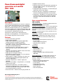
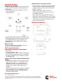
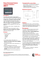
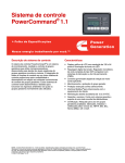
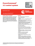
® PowerCommand 1.1 control system Control system description ® The PowerCommand control system is a microprocessor-based generator set monitoring, metering and control system designed to meet the demands of today’s engine driven generator sets. The integration of all control functions into a single control system provides enhanced reliability and performance compared to conventional generator set control systems. These control systems have been designed and tested to meet the harsh environment in which gensets are typically applied. Features Easy to view: HMI 211RS for residential use. 128x64 pixel graphic LED backlight LCD. Easy to use: Tactile buttons for generator set start/stop. Residential standby display for convenient use. Modbus interface: Eliminates need for MODLON. Progressive protective functions: Advanced Overcurrent Protection – Generator set monitoring & protection. Digital voltage regulation: Single phase full wave SCR type regulator compatible with either shunt or PMSG systems. Digital engine speed governing: Provides isochronous frequency regulation. 12 and 24 VDC battery operation. Automatic mains failure: Smooth & automatic transfer and re-transfer of load from utility to generator set & vice-versa. Exerciser clock: Runs generator set exerciser routines for dependability of operation. Warranty and service: Backed by a comprehensive warranty and worldwide distributor service network. Certification: Suitable for us on generator sets that are designed, manufactured, tested and certified to relevant UL, NFPA, ISO, IEC Mil Std., CE and CSA standards. Our energy working for you.™ www.cumminspower.com 2014 Cummins Power Generation Inc. All rights reserved. Cummins Power Generation and Cummins are registered trademarks of Cummins Inc. PowerCommand, InPower and “Our energy working for you.” are trademarks of Cummins Power Generation. Other company, product, or service names may be trademarks or service marks of others. Specifications are subject to change without notice. S-1566d (1/14) Page 1 of 7 PowerCommand digital generator set control PCC 1302 • Supports dual fuel control. • Automatic Mains Failure function built in generator set controller.Modbus interface - for interconnecting to customer equipment. • Configurable inputs and outputs - Four discrete inputs and two dry contact relay outputs. • Warranty and service - Backed by a comprehensive warranty and worldwide distributor service network. • Certifications - Suitable for use on generator sets that are designed, manufactured, tested and certified to relevant UL, NFPA, ISO, IEC, Mil Std., CE and CSA standards. Base control functions Description The PowerCommand generator set control is suitable for use on a wide range of generator sets in non-paralleling applications. The PowerCommand control is compatible with shunt or PMG excitation style. It is suitable for use with reconnectable or non-reconnectable generators, and it can be configured for any frequency, voltage and power connection from 120-600 VAC line-to-line. Power for this control system is derived from the generator set starting batteries. The control functions over a voltage range from 8 VDC to 30 VDC. Features • 12 and 24 VDC battery operation. • Digital voltage regulation. • Digital engine speed governing (where applicable) - Provides isochronous frequency regulation. • Full authority engine communications (where • • • • • • • • • applicable) - Provides communication and control with the Engine Control Module (ECM). Common harnessing - with higher feature Cummins Power Generation controls allows for easy field upgrades. Generator set monitoring - Monitors status of all critical engine and alternator functions. Digital genset metering (AC and DC). Genset battery monitoring system - to sense and warn against a weak battery condition. Engine starting - Includes relay drivers for starter, fuel shut off (FSO), glow plug/spark ignition power and switch B+ applications. Generator set protection - Protects engine and alternator. Advanced serviceability - using InPower™, a PC-based software service tool. Environmental protection - The control system is designed for reliable operation in harsh environments. The main control board is a fully encapsulated module that is protected from the elements. Exerciser function – Routine exercising of generator set. HMI capability Operator adjustments - The HMI includes provisions for many set up and adjustment functions. Generator set hardware data - Access to the control and software part number, generator set rating in KVA and generator set model number is provided from the HMI or InPower. Data logs - Includes engine run time, controller on time, number of start attempts. Fault history - Provides a record of the most recent fault conditions with control hours time stamp. Up to 10 events are stored in the control non-volatile memory. Alternator data - Voltage (single or three phase line-to-line and line-to-neutral) - Current (single or three phase) - KVA (three phase and total) - Frequency Engine data - Starting battery voltage Engine speed Engine temperature Engine oil pressure Partial Full Authority Engine (FAE) data (where applicable) Service adjustments - The HMI includes provisions for adjustment and calibration of generator set control functions. Adjustments are protected by a password. Functions include: - Engine speed governor adjustments - Voltage regulation adjustments - Cycle cranking - Configurable fault set up - Configurable output set up - Meter calibration - Units of measurement Our energy working for you.™ www.cumminspower.com 2014 Cummins Power Generation Inc. All rights reserved. Cummins Power Generation and Cummins are registered trademarks of Cummins Inc. PowerCommand, InPower and “Our energy working for you.” are trademarks of Cummins Power Generation. Other company, product, or service names may be trademarks or service marks of others. Specifications are subject to change without notice. S-1566d (1/14) Page 2 of 7 Engine control SAE-J1939 CAN interface to full authority ECMs (where applicable) - Provides data swapping between genset and engine controller for control, metering and diagnostics. 12 VDC/24 VDC battery operations - PowerCommand will operate either on 12 VDC or 24 VDC batteries. Isochronous governing (where applicable) - Capable of controlling engine speed within +/-0.25% for any steady state load from no load to full load. Frequency drift will not exceed +/-0.5% for a 33 °C (60 °F) change in ambient temperature over an 8 hour period. Temperature dependent governing dynamics (with electronic governing) - Modifies the engine governing control parameters as a function of engine temperature. This allows the engine to be more responsive when warm and more stable when operating at lower temperature levels. Remote start mode - Accepts a ground signal from remote devices to automatically start the generator set and immediately accelerate to rated speed and voltage. The remote start signal will also wake up the control from sleep mode. The control can incorporate a time delay start and stop. Remote and local emergency stop - The control accepts a ground signal from a local (genset mounted) or remote (facility mounted) emergency stop switch to cause the generator set to immediately shut down. The generator set is prevented from running or cranking with the switch engaged. If in sleep mode, activation of either emergency stop switch will wake up the control. Sleep mode - The control includes a configurable low current draw state to minimize starting battery current draw when the genset is not operating. The control can also be configured to go into a low current state while in auto for prime applications or applications without a battery charger. Engine starting - The control system supports automatic engine starting. Primary and backup start disconnects are achieved by one of three methods: magnetic pickup, battery charging alternator feedback or main alternator output frequency. The control also supports configurable glow plug control when applicable. Cycle cranking - Configurable for the number of starting cycles (1 to 7) and duration of crank and rest periods. Control includes starter protection algorithms to prevent the operator from specifying a starting sequence that might be damaging. Time delay start and stop (cooldown) - Configurable for time delay of 0-300 seconds prior to starting after receiving a remote start signal and for time delay of 0-600 seconds prior to shut down after signal to stop in normal operation modes. Default for both time delay periods is 0 seconds. Alternator control The control includes an integrated line-to-line sensing voltage regulation system that is compatible with shunt or PMG excitation systems. The voltage regulation system is full wave rectified and has an SCR output for good motor starting capability. Major system features include: Digital output voltage regulation - Capable of regulating output voltage to within +/-1.0% for any loads between no load and full load. Voltage drift will not exceed +/-1.5% for a 40 ºC (104 ºF) change in temperature in an eight hour period. On engine starting or sudden load acceptance, voltage is controlled to a maximum of 5% overshoot over nominal level. The automatic voltage regulator feature can be disabled to allow the use of an external voltage regulator. Torque-matched V/Hz overload control - The voltage rolloff set point and rate of decay (i.e. the slope of the V/Hz curve) is adjustable in the control. Protective functions On operation of a protective function the control will indicate a fault by illuminating the appropriate status LED on the HMI, as well as display the fault code and fault description on the LCD. The nature of the fault and time of occurrence are logged in the control. The service manual and InPower service tool provide service keys and procedures based on the service codes provided. Protective functions include: Battle short mode When enabled and the battle short switch is active, the control will allow some shutdown faults to be bypassed. If a bypassed shutdown fault occurs, the fault code and description will still be annunciated, but the genset will not shutdown. This will be followed by a fail to shutdown fault. Emergency stop shutdowns and others that are critical for proper operation are not bypassed. Please refer to the Control Application Guide or Manual for list of these faults. Configurable alarm and status inputs The control accepts up to four alarm or status inputs (configurable contact closed to ground or open) to indicate a configurable (customer-specified) condition. The control is programmable for warning, shutdown or status indication and for labeling the input. Our energy working for you.™ www.cumminspower.com 2014 Cummins Power Generation Inc. All rights reserved. Cummins Power Generation and Cummins are registered trademarks of Cummins Inc. PowerCommand, InPower and “Our energy working for you.” are trademarks of Cummins Power Generation. Other company, product, or service names may be trademarks or service marks of others. Specifications are subject to change without notice. S-1566d (1/14) Page 3 of 7 Emergency stop Alternator protection Annunciated whenever either emergency stop signal is received from external switch. High AC voltage shutdown (59) - Output voltage on any phase exceeds preset values. Time to trip is inversely proportional to amount above threshold. Values adjustable from 105-130% of nominal voltage, with time delay adjustable from 0.1-10 seconds. Default value is 110% for 10 seconds. General engine protection Low and high battery voltage warning - Indicates status of battery charging system (failure) by continuously monitoring battery voltage. Weak battery warning - The control system will test the battery each time the generator set is signaled to start and indicate a warning if the battery indicates impending failure. Fail to start (overcrank) shutdown - The control system will indicate a fault if the generator set fails to start by the completion of the engine crack sequence. Low AC voltage shutdown (27) - Voltage on any phase has dropped below a preset value. Adjustable over a range of 50-95% of reference voltage, time delay 2-20 seconds. Default value is 85% for 10 seconds. Overcurrent warning/shutdown - Implementation of the thermal damage curve with instantaneous trip level calculated based on current transformer ratio and application power rating. Fail to crank shutdown - Control has signaled starter to crank engine but engine does not rotate. Cranking lockout - The control will not allow the starter to attempt to engage or to crank the engine when the engine is rotating. Hydro mechanical fuel system engine protection Overspeed shutdown - Default setting is 115% of nominal. Low lube oil pressure warning/shutdown - Level is preset (configurable with InPower) to match the capabilities of the engine used. Control includes time delays to prevent nuisance alarms. High lube oil temperature warning/shutdown - Level is preset (configurable with InPower) to match the capabilities of the engine used. Control includes time delays to prevent nuisance alarms. High engine temperature warning/shutdown - Level is preset (configurable with InPower) to match the capabilities of the engine used. Control includes time delays to prevent nuisance alarms. Low coolant temperature warning – Indicates that engine temperature may not be high enough for a 10 second start or proper load acceptance. Sensor failure indication - Logic is provided on the base control to detect analog sensor or interconnecting wiring failures. Under frequency shutdown (81 u) - Generator set output frequency cannot be maintained. Settings are adjustable from 2-10 Hz below nominal governor set point, for a 5-20 second time delay. Default: 6 Hz, 10 seconds. Over frequency shutdown/warning (81o) - Generator set is operating at a potentially damaging frequency level. Settings are adjustable from 2-10 Hz above nominal governor set point for a 1-20 second time delay. Default: 6 Hz, 10 seconds, enabled. Full authority electronic engine protection Loss of sensing voltage shutdown - Shutdown of generator set will occur on loss of voltage sensing inputs to the control. Engine fault detection is handled inside the engine ECM. Fault information is communicated via the SAE-J1939 data link for annunciation in the HMI. Field overload shutdown - Uses field voltage to shutdown generator set when a field overload condition occurs. Our energy working for you.™ www.cumminspower.com 2014 Cummins Power Generation Inc. All rights reserved. Cummins Power Generation and Cummins are registered trademarks of Cummins Inc. PowerCommand, InPower and “Our energy working for you.” are trademarks of Cummins Power Generation. Other company, product, or service names may be trademarks or service marks of others. Specifications are subject to change without notice. S-1566d (1/14) Page 4 of 7 Advanced functions Communications connections include: Automatic mains failure* The built in AMF feature provides the automatic transfer and re-transfer of the load from utility to generator set and vice-versa. - Automatically starts-stops the generator set in the event of utility failure. - Annunciates faults. - PC tool interface: This RS-485 communication port allows the control to communicate with a personal computer running InPower or PowerCommand for ® Windows software. - Modbus RS-485 port: Allows the control to communicate with external devices such as PLCs using Modbus protocol. Note - An RS-232 or USB to RS-485 converter is required for communication between PC and control. - Networking: This RS-485 communication port allows connection from the control to the other Cummins Power Generation products. Mechanical drawings * A utility voltage monitoring sensor (as shown in the AMF diagram above) must be connected in order to use the AMF feature on the 1302 control. Use Schneider Electric Relay RSB1A120U7, Socket RSZE1S35M. Exerciser clock The exerciser clock runs the generator set exerciser routines for dependability of operation. Field control interface Input signals to the base control include: - Remote start - Local and emergency stop - Configurable inputs: Control includes (4) input signals from customer discrete devices that are configurable for warning, shutdown or status indication, as well as message displayed Output signals from the PowerCommand control include: - Configurable relay outputs: Control includes (2) relay output contacts rated at 2 A. These outputs can be configured to activate on any control warning or shutdown fault as well as ready to load, not in auto, common alarm, common warning and common shutdown. - Ready to load (generator set running) signal: Operates when the generator set has reached 90% of rated speed and voltage and latches until generator set is switched to off or idle mode. Our energy working for you.™ www.cumminspower.com 2014 Cummins Power Generation Inc. All rights reserved. Cummins Power Generation and Cummins are registered trademarks of Cummins Inc. PowerCommand, InPower and “Our energy working for you.” are trademarks of Cummins Power Generation. Other company, product, or service names may be trademarks or service marks of others. Specifications are subject to change without notice. S-1566d (1/14) Page 5 of 7 PowerCommand human machine interface HMI211 Communications connections - PC tool interface - This RS-485 communication port allows the HMI to communicate with a personal computer running InPower. - This RS-485 communication port allows the HMI to communicate with the main control board. Mechanical drawing Description This control system includes an intuitive operator interface panel that allows for complete genset control as well as system metering, fault annunciation, configuration and diagnostics. The interface includes five generator set status LED lamps with both internationally accepted symbols and English text to comply with customer needs. The interface also includes an LED backlit LCD display with tactile feel soft-switches for easy operation and screen navigation. It is configurable for units of measurement and has adjustable screen contrast and brightness. The run/off/auto switch function is integrated into the interface panel. All data on the control can be viewed by scrolling through screens with the navigation keys. The control displays the current active fault and a time-ordered history of the five previous faults. Features • LED indicating lamps: • • • • • • - remote start - not in auto - shutdown - warning - auto - run 128 x 64 pixels graphic LED backlight LCD. Four tactile feel membrane switches for LCD defined operation. The functions of these switches are defined dynamically on the LCD. Two tactile feel membrane switches dedicated for off and back. Allows for complete genset control setup. Certifications: Suitable for use on generator sets that are designed, manufactured, tested and certified to relevant UL, NFPA, ISO, IEC, Mil Std., CE and CSA standards. HMI 211RS provides convenience for residential use. Software InPower (beyond 6.0 version) is a PC-based software service tool that is designed to directly communicate to PowerCommand generator sets and transfer switches, to facilitate service and monitoring of these products. Environment The control is designed for proper operation without recalibration in ambient temperatures from -40 ºC (-40 ºF) to +70º C (158 ºF), and for storage from -55 ºC (-67 ºF) to +80 ºC (176 ºF). Control will operate with humidity up to 95%, non-condensing. The HMI is designed for proper operation in ambient temperatures from -40 ºC* (-40 ºF) to +70 ºC (158 ºF), and for storage from -40 ºC* (-40 ºF) to +80 ºC (176 ºF). The control board is fully encapsulated to provide superior resistance to dust and moisture. Display panel has a single membrane surface, which is impervious to effects of dust, moisture, oil and exhaust fumes. This panel uses a sealed membrane to provide long reliable service life in harsh environments. The control system is specifically designed and tested for resistance to RFI/EMI and to resist effects of vibration to provide a long reliable life when mounted on a generator set. The control includes transient voltage surge suppression to provide compliance to referenced standards. * Heater accessory (pn: A040H853) is available for enhanced operation below -20 ºC Our energy working for you.™ www.cumminspower.com 2014 Cummins Power Generation Inc. All rights reserved. Cummins Power Generation and Cummins are registered trademarks of Cummins Inc. PowerCommand, InPower and “Our energy working for you.” are trademarks of Cummins Power Generation. Other company, product, or service names may be trademarks or service marks of others. Specifications are subject to change without notice. S-1566d (1/14) Page 6 of 7 Certifications Accessories PowerCommand meets or exceeds the requirements of the following codes and standards: 1301-1302 Upgrade Kit (HM) 0541-1431 PowerCommand 500 (LAN) A040X126 - NFPA 110 for level 1 and 2 systems. - ISO 8528-4: 1993 compliance, controls and switchgear. - CE marking: The control system is suitable for use on generator sets to be CE-marked. - EN 50081-1,2 residential/light industrial emissions or industrial emissions. - EN 50082-1,2 residential/light industrial or industrial susceptibility. - ISO 7637-2, level 2; DC supply surge voltage test. - Mil Std 202C, Method 101 and ASTM B117: Salt fog test. - PowerCommand control systems and generator sets are designed and manufactured in ISO 9001 certified facilities. - UL 508 recognized or Listed and suitable for use on UL 2200 Listed generator sets. - CSA C282-M1999 compliance. - CSA 22.2 No. 14 M91 industrial controls. Remote HMI 211 0541-1394 Remote HMI 211RS A046K103 I/O Expansion (Aux 101) 0541-1291 HMI Heater Accessory Kit A040H853 Parts ordering information 1302 Control Board 0327-1617-02 1302 control Board – Arrow A043W505 Aux 104 (Governor Control) 0327-1507 HMI 211 Without Heater 0300-6014 HMI 211 with Heater A026G237 Additional resources Warranty Resource Where to Find All components and subsystems are covered by an express limited one year warranty. Other optional and extended factory warranties and local distributor maintenance agreements are available. 1302 Service Manual QSOL Accessories Catalog cumminspower.com Additional Controls Information PowerSuite Library See your distributor for more information Cummins Power Generation Americas 1400 73rd Avenue N.E. Minneapolis, MN 55432 USA Phone: 763 574 5000 Fax: 763 574 5298 Europe, CIS, Middle East and Africa Manston Park Columbus Ave. Manston Ramsgate Kent CT 12 5BF United Kingdom Phone 44 1843 255000 Fax 44 1843 255902 Asia Pacific 10 Toh Guan Road #07-01 TT International Tradepark Singapore 608838 Phone 65 6417 2388 Fax 65 6417 2399 Warning: Back feed to a utility system can cause electrocution and/or property damage. Do not connect to any building’s electrical system except through an approved device or after building main switch is open. Our energy working for you.™ www.cumminspower.com 2014 Cummins Power Generation Inc. All rights reserved. Cummins Power Generation and Cummins are registered trademarks of Cummins Inc. PowerCommand, InPower and “Our energy working for you.” are trademarks of Cummins Power Generation. Other company, product, or service names may be trademarks or service marks of others. Specifications are subject to change without notice. S-1566d (1/14) Page 7 of 7