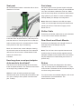
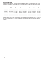
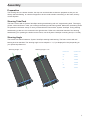
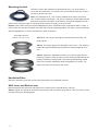
1
Manual
Thank you for deciding for a Liteville.
Watch out for the latest updates of this manual on
www.liteville.de -> Service -> Manual 301 Mk12
and read the entire manual before assembling your bike.
301 Mk12
Restrictions
Please note that not all components available on the market are suitable for your Liteville 301 frame. With the
following parts, restrictions are known:
Fork
Forks with a maximum of 570 mm built height are suitable, however make sure that it does not interfere with
the frame when compressed. Forks known to us that do not fit include all Fox 32 Talas 26” forks before 2014.
Crankset/Bottom Bracket
Not all cranksets/ bottom brackets are suitable. Install a BSA BB with a width of 73 mm. Make sure that
both the crank arms and the Syntace SCS Chain
Guide do not touch the frame.
All common Shimano and SRAM direct mount front
derailleurs are compatible with the frame if they are
operated from above or sideways.
2
Seat post
All Liteville frames feature a seat tube with an inner
diameter of 34.9 mm.
Seat clamp
We advice you to use a Syntace SuperLock2 seat
clamp or a MicroLock 38. In case you use a different
one, this is to feature a diameter of 38 mm. Make
sure the seat clamp does not interfere with the damping system of your frame. In order to reaffirm this,
entirely deflate your damper and compress it.
Note: With all 301 frames in size XS, the SuperLock2 is to be mounted with the quick release lever
pointing to the front. This does not apply for the
MicroLock 38.
Shifter Cable
Exclusively use shifter cables with an outer diameter
In order to prevent damage, the seat post is to be
inside the frame at least 120 mm, if the seat post is
less than 200 mm. The seat post is to be inside the
frame at least 140 mm if it exceeds 200 mm. Refer
to the picture for the way of measuring.
Black 301 frames have a laser indication showing
the minimum insert of the seat post. This indication
refers to the 140 mm mark. Liteville Works Finish
frames do not have this
indication.
How long does a seat post adapter
shim needs to be at least?
The shim is to be at least as long as the minimum
insert as explained above. The minimum insert does
not change using a reduction shim.
Advice: In case of doubt, purchase the longer
reduction shim such as the Syntace Post Shim Light
31.6 (Art. 113299) or the Syntace Post Shim 30.9
(Art. 114203).
of 4 mm such as the Shimano SIS-SP41.
Rear Shock and Shock Mounts
Exclusively use dampers with a length of 200 mm
while the travel of the damper may not
exceed 57 mm.
Note: The 301 frame has a special kinematic and
therefore does not work perfectly together with all
dampers available on the market. This is the reason
why the dampers we install initially are tuned in a
specific way.
Brakes
Liteville 301 frames are designed for disc brakes
only. 301 frames after model Mk8 feature a 7” postmount socket. The brake can be mounted directly on
the frame using 180 mm disks.
For 210 mm discs and suitable adapters, refer to the
manufacturers’ recommendations. The
same counts for forks.
3
Wheelset & Tires
Depending on the frame size, the Liteville 301 is compatible with different wheel sizes and tire sizes. In the
table below you will find on the left of the slash the rear wheel size, on the right of the slash the front wheel
size.
XC
All Mountain
Enduro
travel
XS
S
M
L
XL
XXL
100 - 120 mm
26“ / 26“
27.5“ / 27.5“
27.5“ / 29“
27.5“ / 29“
27.5“ / 29“
29“ / 29“
27.5“ / 29“
29“ / 29“
29“ / 29“
29“ / 29“
24“ / 26“
26“ / 26“
27.5“ / 27.5“
27.5“ / 27.5“
27.5“ / 27.5“
27.5“ / 29“
26“ / 26“
26“ / 27.5“
27.5“ / 29“
27.5“ / 29“
27.5“ / 29“
29“ / 29“
120 - 140 mm
160 - 180 mm
24“ / 26“
24“ / 26“
26“ / 27.5“
26“ / 27.5“
26“ / 27.5“
27.5“ / 29“
26“ / 26“
26“ / 26“
27.5“ / 27.5“
27.5“ / 27.5“
27.5“ / 27.5“
29“ / 29“
Note that the rear tire may touch the frame slightly if the rear suspension is compressed a 100 %. In case the
tire touches the frame, this is no problem except for the rubber left on the frame. Also refer to the manual of
your fork.
4
Assembly Preparation
The steering tube, the bottom bracket, the drop out and the brake sockets are prepared so that you can
directly start assembling. In case there appears to be the need to deburr something on the frame, directly
contact Syntace.
Steering Tube/Fork
The frame comes with a Syntace VarioSpin steering head bearing with a 0° angle bearing shell. Thoroughly
grease contact surfaces in case you exchange the bearings and bearing shells. Make sure the bearing shells
are pressed in the frame evenly. In case you assemble the frame with a Syntace VarioSpin Tuning steering
head bearing, make sure it is mounted in the right direction. Refer to the individual manual of the steering
head bearing. For pressing the shells into the frame, use the Syntace VarioSpin mounting tool (Art. 115125).
Steering Angle
The Liteville 301 Mk12 features a Syntace VarioSpin steering head bearing. The frame comes with a 0°
bearing shell as standard. The steering angle can be adapted +/- 1,5° (as displayed in blue) depending on
your personal preferences.
Steering Angle -1.5°
Steering Angle +1.5°
Frame size
Syntace Art.
XS
114951
S
114944
M
114890
L
114906
XL
114913
XXL
114913
5
Mounting the fork
The frame comes with adapters for tapered forks only (1,5” at the bottom, 1
1/8” at the top). Mount the 1,5” bottom cone on the steering tube first so that it
sits evenly on the fork crone.
Note: The reduction kit for 1 1/8” forks is available as an option at Syntace
(Art. 114593). When mounting a 1 1/8” fork, the assembly of the upper steering
head bearing remains the same; at the bottom, the specific adapters as ordered are to be mounted. Again, the bearing shells need to sit evenly on the fork crone.
Hinweis: Note: When using the Syntace MegaSpacer kit in combination with a Liteville 301 Mk11 or later, a
0.6 mm shim is to be laid in between the Super Spin Cap and the MegaSpacer. The shim comes as standard
with the MegaSpacer or can be ordered as an option at Syntace.
SuperSpin tapered
bottom 1.5“, top 1 1/8“
Advice: Do not cut your steering tube before the first test ride, you
might regret it.
Advice: Thoroughly grease the SuperSpin cap of your 1 1/8” steering
head bearing as this additionally protects the bearings against corrosion.
Advice: Tighten the adjustment screw of your stem properly before
loosening it again in order to make sure the steering head bearings sit
properly inside the bearing shells. The steering head bearing should
work more smoothly afterwards while the adjustment is easier. The
upper fork crone must not touch the frame.
Handlebar/Stem
Mount the handlebar and stem to the fork as described in the individual manuals.
Shift Lever and Brake Lever
Mount and adjust the shift lever and brake lever according to the manufacturers’ manuals.
Advice: Tighten the shift lever and brake lever properly, but so that they may twist in case of a crash in order
to protect them from breaking apart.
6
Bottom Bracket, Crankset, Front Derailleur
Mount the Direct Mount front derailleur on the socket of the frame. After mounting the crankset, adjust the
front derailleur as recommended by the manufacturer looking at the distance between the upper chain ring
and the front derailleur. You may only mount front derailleurs that are operated from above or sideways (see
picture for detailed information).
Shimano Sideswing front derailleur including the first shift
cable attachment
SRAM front derailleur operated from above
Advice: The frame comes with a pad that can be attached to the front derailleur. Mount the pad in order
to reduce noises.
You may now mount the two bottom brackets as described by the manufacturers. Thoroughly grease the
frame beforehand.
Caution: Mount the BSA bottom bracket as described by the manufacturers with a width of 73 mm. Mind that
there is enough space in between the crank arm and the chain stay resp. in between the crank arm and the
SCS Chain Guide.
7
Cable and Brake Pipe Routing
Rear Derailleur
Vario Seat post (Stealth)
Front Derailleur (Side Swing)
Rear Brake
Front Brake
Picture displays an assembly with a 2 x 11 drivetrain, brakes and vario seat post operated from the handlebar.
Rear Brake
Rear Derailleur
Vario Seat post (Stealth)
Front Derailleur (Side Swing)
Picture displays the assembly with an 2 x 11 drivetrain, brakes and vario seat post on the down tube.
8
The frame comes with enough cable holders for any routing possible.
Note: The cable for the rear derailleur and the rear brake are mounted on the down tube. Generally tighten
the holders gently, as the holders are supposed to only keep the cables from getting out of place. Tightening
the holders too hard may damage the cable or brake pipe.
The shift cable for the front derailleur operated from above is inside the top tube. The entrance for this cable
is to be found at the bottom of the top tube close to the steering tube. The exit of the cable is to be found
close to the seat tube. Refer to the picture above for the exact routing. The cable should neither be too short
nor too long in order to guarantee a perfectly working shifting performance.
Shift Cable Routing for the Rear Derailleur
The shift cable for the rear derailleur is to be laid
inside the down tube and the chain stay. In order to
further prevent the cable from corrosion and attrition,
we use an additional plastic pipe. Do not remove this
plastic pipe. In case you have taken it out of the
frame before or in case the rear end has been
detached, put it back into its seating as displaced in
green in the picture below.
9
The exit for the shifter cable is at thelower rear end
of the right chain stay.
Exchange of the Shift Cable
Leave the black plastic pipe in place.
Cut the shift cable guide with a 45° as shown.
The exit of the shift cable is at the rear end of the
chain stay. Insert the cable into the frame starting
at the down tube until it hits the chain stay. Form a
“lever” with the cable and twist and push it simultaneously into the chain stay. Matters are simplified
as you demount the rear shock and move the rear
frame triangle upwards and downwards..
Alternative
Cut the end piece of a shift cable and push it into the frame without the cable guide. Start at the down tube.
Afterwards push the cable guide onto the cable until it finds its way out of the frame at the rear end of the
chain stay.
10
Brake Pipe Routing
Mind that the brake pipe is long enough as displayed
in the picture. The brake pipe is shortened when the
rear suspension of the frame is working
Use the nylon holders for the brake pipe that come
with the frame. In case you use cable ties, do not
tighten them too hard in order to make sure that the
brake pipe can move freely. It might creak otherwise
when the rear suspension is working.
Caution: The way the brake pipe is rooted in the
picture works for brake calipers where the output
of the brake pipe is adjustable. The routing may be
different with other models.
Shimano Rear Derailleur
We recommend mounting Shadow Technology rear derailleurs exclusively, no matter whether the derailleur is
mounted conventionally or as a Direct Mount.
We do not recommend to assemble the bike with an old Shimano rear derailleur for Liteville 301 Mk8 frames
or later. These rear derailleurs do not harmonize with the extraordinarily tight routing of the shift cable guide.
Mount and tune the rear derailleur as recommended by the manufacturer.
SRAM Rear Derailleur
The frame works with the following SRAM rear derailleurs:
11-speed: X1, XX1, X01
10-speed: X01, XX, X0, X9, X7, X5 (including Type 2.1)
This is why Shimano and SRAM rear derailleurs work best:
- direct cable routing without redundant cable curves
- no friction due to cable curves
- less bumping of the rear derailleur; the chain works more smoothly
- more protection against rocks and branches
- less noises and friction
Mount and tune the rear derailleur as recommended by the manufacturer.
Note: Adjusting the rear derailleur, mind that it has enough space to move freely towards the chain stay.
11
Seat tube/seat post/saddle
Before inserting the seat post in the seat tube for the first time, reassure that the inner surface is even and
deburred properly. In case of doubt, clean the tube with a 180 sandpaper. Also mind the minimum insert as
described in “Seat post” above. You may now assemble the seat post and saddle as described in the manual
of the seat post.
Advice: Shorten the seat post to its minimum insert only after you have reassured that the seat height is
measured correctly. Remember that different shoe heights as well as pedals may influence the seat height.
If you shorten the seat post you will profit from the minimal weight as well as from the fact that you can insert
the saddle to its maximum for descending: weight reduction for free!
Caution: Mind the wear of the seat post. Inserting the seat post frequently, particularly in dirty conditions, the
material may show signs of usage and loose its original strength. Carbon fiber seat posts are worn out faster
than aluminum seat posts. In order to minimize this effect, the seat post should be removed after every ride in
dirty conditions and be cleaned properly. Do not forget to also clean the seat tube from inside. The seat post
is to be measured frequently and must not come below 34,7 mm. If this is the case, the seat post is to be exchanged. If you keep riding the worn out seat post, the frame can be damaged at the seat clamp irreversibly.
Cracks inside the frame might be a consequence.
Syntace X-12 through axle
The Syntace X-12 through axle is the only system that offers the possibility to adjust the toe as well as the
camber of your bike. As a result of this design, we are able to manufacture the frame even more accurately
The screw (5 mm Allen key) is only meant to hold the
derailleur hanger. It does not have to be loosened in
order to remove the axle.
Note: the axle insert fits your frame exactly, it is
adjusted and marked. The 0,5 mm or 1,0 mm insert is
aligned correctly if the marked groove is parallel to the
clamping slot of the derailleur hanger.
12
Damper setting
Adjusting the preload
In order to have your rear suspension work effectively, the damper is to be adjusted correctly. For the adjustment, go through the following steps:
- find an even spot and someone to help you
- sit on your 301 as if you would go on a ride (including backpack, helmet, etc.) and start riding
- the compression stage is to be open (seen from above, the blue lever points to the right)
- as you look down on your frame, mind the SAG indicators (dynamic lever) on the frame and the bell crank.
Caution: do not try to touch the pins as this might result in serious injuries. The Rock Shox Monarch RT3
DebonAir works best with a 30 % SAG.
Dynamic Level Adjustment:
Our recommendation: pin above frame pin
Hard setting: pin on pin
The pin indication works with the RockShox Monarch RT3 DebonAir exclusively.
Note: Even an additional backpack increases the weight on the rear axle noticeably. We thus recommend
you to check and adjust the SAG frequently.
Rebound adjustment
Sit on your bike and ride down a sidewalk. The rear suspension should “bump” only once. In case it does
more often, close the rebound further. With most dampers, this is indicated with a “+” or a turtle. The adjustment lever most of the time is red.
On the other hand, the rear suspension should not react too slowly either in order to prevent the bike from
becoming too hard with several impacts following each other. In this case, readjust the rebound. This is
indicated with a “-“ or a rabbit.
Also refer to the manufacturers’ manual and recommendations.
13
Build-in interfaces
Vario seat posts with remote control
The 301 Mk12 is prepared for the RockShox Reverb
Stealth seat post and similar products on the market.
The cable may be inserted in the seat tube at the left
side close to the bottom bracket. The cable is to be
mounted as described in the manufacturers’ manual.
You may also assemble the bike with a seat post that features an external cable routing for which the frame
features long holes at the bottom of the top tube as displayed in picture 1 and 2.
Picture 1
Picture 2
Syntace SCS Chain Guide
301 Mk8 models and later versions feature a specific attachment point for the Syntace SCS Chain Guide.
This can be found at the bottom of the chain stay (refer to pictures below.) The Syntace SCS Chain Guide
guarantees an unprecedented performance for 2-speed and 3-speed cranksets while also being extraordinarily light.
14
RockGuard derailleur protector
The 301 frame features an integrated attachment
point for the Syntace RockGuard SL (black Art.
116757; raw Art. 117013), the patented bodyguard
for your rear derailleur and derailleur hanger. It keeps
you from trouble with bent derailleur hangers and
instead results in reliable performance all year long.
Note: Mounting the Syntace RockGuard SL in combination with a SRAM rear derailleur, mind the specific
manual of the RockGuard SL.
The frame comes with two different derailleur hangers as standard:
Shimano Direct Mount rear derailleur
Standard rear derailleur hanger for Shimano-Shadow and
SRAM
15
Maintenance and care
Bearings frame / VarioSpin headset
With conventional usage, the bearings do not have to be dismounted, greased or cleaned. In case a bearing
gets damaged anyways, you may order the respective bearing type at your Liteville dealer and have it exchanged there or order it at Syntace directly.
Note: The bearing in the top tube as well as in the “Horstlink” (connection of seat tube and chain stay) can
be greased without being demounted. We recommend the Syntace GreaseGun for this maintenance (Art.
116931) for most effective results.
Advice: Never point at your bearings with a high-pressure water jet, as this can easily damage them (also
read the chapter “Washing”). After all, too much “maintenance” may even harm your bearings.
Screws
The screws in your frame are all made from Titanium or Aluminum and are produced specifically for Liteville
frames. They are all mounted with screwlock. Nonetheless, you are to check the correct tightening torque
frequently as described on page 18. Black frames feature torque indications right next to the individual screw.
In case you loose or damage a screw, you may order the respective screw at your Liteville dealer and have it
exchanged there or order it at Syntace directly. In case you exchange a screw, apply screwlock and wait for it
to be hardened entirely.
Caution: Watch out! In case a screw can actually be twisted as the tightening torque is checked, the
screwlock is broken and thus needs to be exchanged. The screw needs to be secured again. Unscrew it,
clean it and reassemble everything with enough screwlock (refer to chart below). We have summed up a
“Loctite Basics” on www.liteville.de > FAQ.
Advice as to creaking: Oftentimes, you need to check for possible creaking sources where you do not
expect them. It might appear to creak in the back of the bike while the noises actually origin up front. Find
further information on www.liteville.de > FAQ
16
Rear suspension travel of works finish bell cranks:
Even if the travel on a Works Finish bell crank is not indicated explicitly, you can derive the travel from the
position of the SAG indicator “Dynamic Level” as displayed in the picture below.
140 mm Lever
160 mm Lever
Works Finish surface
Besides our black frames as well as custom painted frames, we offer limited edition “Works Finish” frames.
The Liteville Works Finish is a genuine raw aluminum surface, free of any kind of protection pain, meaning it
is no aluminum simulation. The frame actually shows the signs of the original manufacturing process.
Stains are thus common, the frame may even change its color slightly which leads to the natural charm of
a grown patina. By the way, the surface can be reprocessed at all times either chemically or mechanically
with a Scotch-Brite-Finish or by being polished manually. The frame comes standard with two Scotch Brite
grinding fleeces. Try using it on a spot that is not seen directly.
Note: The Works Finish frame also comes with 3M stickers. It is
your choice if you put them on your frame or if you do not.
17
18
10-20 Nm
X-12 Axle
10 Nm
10 Nm
10Nm
6 Nm
10 Nm
summed up a “Loctite Basics” on www.liteville.de > FAQ.
and reassemble everything with enough screwlock. We have
needs to be secured again. Unscrew it, clean it with degreaser
screwlock is broken and thus needs to be renewed; the screw
Watch out! In case a screw can actually be twisted, the
Syntace Torque Tool.
For tightening screws, always use a torque meter such as the
6 Nm
10 Nm
10 Nm
10 Nm
20 Nm screw
30 Nm insert
1 Nm
15 Nm
15 Nm
Screws: Maximum tightening torque
green: hard screwlock
blue: intermediate screwlock
white = no screwlock
19
Bearing HorstLink
even harm your bearings.
Bearing lever
Bearing chain stay
Needle bearing
damper mount
Needle bearing top tube
damage them (also read the chapter “Washing”). After all, too much “maintenance” may
Advice: Never point at your bearings with a high pressure water jet, as this can easily
does not drop into the frame.
spirit before applying the screwlock. Do this with a cotton stick and make sure that it
hard screwlock (such as Loctite, Syntace Bond 48). Degrease the bearing shell with
The marked bearings – in case they are to be exchanged – need to be mounted with
Lager: Assembly with screwlock
green = hard screwlock
blue = intermediate screwlock
white = no screwlock
Syntace GmbH Am Mühlbach 5c D - 87487 Wiggensbach
Tel. +49 (0)8370 929988 Fax +49 (0)8370 929888 [email protected]
Vertrieb für Deutschland:
Syntace GmbH Dammweg 1 D - 83342 Tacherting
Tel. +49 (0)8634 66666 Fax +49 (0)8634 6365 [email protected]
Stand: 27.03.2015
20