1
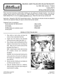
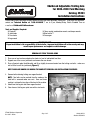
Edelbrock Adjustable Trailing Arm
for 2005-2008 Ford Mustang
Catalog #5253
Installation Instructions
Please study these instructions carefully before installing your new Adjustable Trailing Arm. If you have any questions,
contact our Technical Hotline at: 1-800-416-8628, 7 am to 5 pm, Monday-Friday, Pacific Standard Time or
e-mail us at [email protected].
Tools and Supplies Required:
❑ Floorjack
❑ Jackstands
❑ Tire chocks
❑ Lug wrench
❑ 18mm socket, combination wrench, and torque wrench
❑ Blue Loctite™
❑ Grease gun
IMPORTANT NOTE:
Proper installation is the responsibility of the installer. Improper installation will void warranty and may
result in poor performance and engine or vehicle damage.
REMOVAL OF STOCK TRAILING ARMS
1. Place car on level surface and place tire chocks in front of and behind front tires.
2. Support rear of the car on jackstands and remove the rear wheels.
3. Place a floorjack under the differential and lift up slightly to remove tension from the trailing arm bolts - make sure
not to lift the car off the jackstands (Figure 1).
KEEP FLOORJACK UNDER CAR DURING THE COMPLETE REMOVAL AND INSTALLATION PROCEDURE.
4. Remove bolts retaining trailing arm support bracket.
NOTE: Two bolts can be reached from the undercar, the
third bolt is accessed under rear seat. Rear seat lower
cushion is retained by two clips at the front of the cushion.
5. Unbolt front trailing arm bolt from support bracket.
6. Clean frame at trailing arm pivot area with a wire brush.
Fig. 1
©2007 Edelbrock Corporation
Rev. 9/07 - DA/mc
Page 1 of 2
Catalog #5253
Brochure #63-0456
INSTALLATION INSTRUCTIONS
Edelbrock Adjustable Trailing Arm is fully assembled, greased, and ready to install.
1. Install Edelbrock adjustable trailing arm into trailing arm support bracket using supplied spacers. Spacers have a lip
on them that goes into heim joint. Install OEM bolt in the same direction as the factory. Use blue Loctite™ and torque
bolt to 90 ft./lb.
2. Re-install trailing arm support bracket and trailing arm in vehicle. Use blue Loctite™ on threads and torque to
70 ft. /lb.
3. The trailing arm should then pivot smoothly.
4. Pivot trailing arm into position over OE bushing. Install rear bolt in same direction as original.
5. Place one drop of blue Loctite™ on clean threads and torque the nut to 90 ft./lbs.
6. Although Edelbrock Trailing Arm is pre-lubed, you may want to finish your installation by lubing the front bushings with
a greasegun. Be sure to replace the dust caps on the Zerk fittings to prevent dirt and corrosion from damaging the
fitting.
Check all nut and bolt tightness after first 10 miles.
NOTES:
1. Edelbrock Adjustable Trailing arms come pre-adjusted to stock length. Pinion angle can be adjusted by loosening the
jam nuts on the arms and turning the aluminum adjuster sleeve in the center of the arm. Both arms should be
adjusted evenly. A properly installed and adjusted trailing arm will have the spherical ball straight and parallel with
the ball housing. If the ball is twisted in its housing when installed, the arm could fail during suspension articulation.
After adjustment has been made, use a drop of Loctite™ on threads at jam nuts.
2. Jam nuts should be checked periodically for tightness.
3. To further enhance the handling and performance of your Mustang, check our catalog to find out more about Edelbrock
Suspension components such as coil springs, lower trailing arms, strut tower brace, panhard rod, and sub-frame
connectors. To order our catalog, call 1-800-FUN-TEAM.
Edelbrock Corporation, 2700 California St., Torrance, CA 90503
Tech Line: 1-800-416-8628
E-Mail: [email protected]
©2007 Edelbrock Corporation
Rev. 9/07 - DA/mc
Page 2 of 2
Catalog #5253
Brochure #63-0456