1
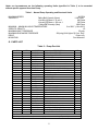
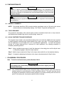
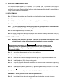
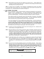
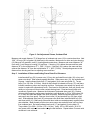
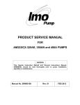
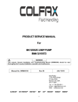
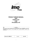
PRODUCT SERVICE MANUAL
FOR
C324AXFS-250/12004 PUMP
WARNING
This Instruction Manual and General Instructions Manual, SRM00046, should
be read thoroughly prior to pump installation, operation or maintenance of
Pump.
SRM00109
Rev. 01 (12-0241)
JUNE, 2012
READ THIS ENTIRE PAGE BEFORE PROCEEDING
FOR THE SAFETY OF PERSONNEL AND TO PREVENT DAMAGE TO THE EQUIPMENT, THE
FOLLOWING NOMENCLATURE HAS BEEN USED IN THIS MANUAL:
DANGER
Failure to observe precautions noted in this box can result in severe bodily injury
or loss of life.
WARNING
Failure to observe the precautions noted in this box can cause injury to personnel
by accidental contact with the equipment or liquids. Protection should be provided
by the user to prevent accidental contact.
CAUTION
ATTENTION
Failure to observe the precautions noted in this box can cause damage or failure
of the equipment.
Non compliance of safety
instructions identified by
the
following
symbol
could affect safety for
persons:
Safety
instructions
where electrical safety
is
involved
are
identified by:
Safety instructions which
shall be considered for
reasons of safe operation of
the pump and/or protection
of the pump itself are
marked by the sign:
ATTENTION
CONTENTS
SAFETY AND TABLE OF CONTENTS
GENERAL INSTRUCTION
INTRODUCTION
DESCRIPTION OF EQUIPMENT
PUMP MODEL IDENTIFICATION
ORDERING INSTRUCTIONS
OPERATION
PARTS LIST
PUMP MAINTENANCE
PUMP DISASSEMBLY
PUMP ASSEMBLY
INSTALLATION, ALIGNMENT AND TROUBLESHOOTING
FIELD AND FACTORY SERVICE AND PARTS
ASSEMBLY DRAWING
2
3
3
3
4
4
5
5
6
6-8
8-11
12
12
13-14
ATTENTION
If operation of this pump is critical to your business, we strongly
recommend you keep a spare pump or major repair kit in stock at all times.
As a minimum, a minor repair kit (o-rings, gaskets, shaft seal and bearings)
should be kept in stock so pump refurbishment after internal inspection can
be accomplished.
2
A. GENERAL INSTRUCTIONS
Instructions found herein cover disassembly, assembly and parts identification of C324AXFS250/12004 pump.
NOTE: Individual contracts may have specific provisions that vary from this manual. Should any
questions arise which may not be answered by these instructions, refer to General
Instructions Manual, SRM00046, provided with your order. For further detailed information
and technical assistance please refer to Imo Pump, Technical/Customer Service
Department, at (704) 289-6511.
This manual cannot possibly cover every situation connected with installation, operation, inspection,
and maintenance of equipment supplied. Every effort was made to prepare text of manual so that
engineering and design data is transformed into most easily understood wording. Imo Pump must
assume personnel assigned to operate and maintain supplied equipment and apply this instruction
manual have sufficient technical knowledge and are experienced to apply sound safety and operational
practices which may not be otherwise covered by this manual.
In applications where equipment furnished by Imo Pump is to become part of processing machinery,
these instructions should be thoroughly reviewed to ensure proper fit of said equipment into overall
plant operational procedures.
WARNING
If installation, operation, and maintenance instructions are not correctly and strictly
followed and observed, injury to personnel or serious damage to pump could result.
Imo Pump cannot accept responsibility for unsatisfactory performance or damage
resulting from failure to comply with instructions.
B. INTRODUCTION
This instruction manual covers the C324AXFS-250/12004 pump.
C. DESCRIPTION OF EQUIPMENT
C324AXFS-250/12004 pump is a positive displacement, rotary screw pump consisting of precision
bored housings that encloses a driven screw (power rotor) and two intermeshing following screws (idler
rotors). These screws when rotating form a succession of closures or cavities. As they rotate, fluid is
moved axially from inlet port to outlet port in a continuous, uniform flow with minimum fluid pulsation
and pump noise. Fluid flowing through pump provides lubrication to moving parts.
3
D. PUMP MODEL IDENTIFICATION
This instruction manual covers Imo C324AXFS-250/12004 pumps. Model of pump is identified on
pump nameplate. Refer to Figure 1 and Table 1 for instructional keys when using this manual.
C 324A
X
F
S
- 250 / 12004
Special Bill
of Material
Designator
Design
Modification
Pump
Series
Power Rotor
Diameter
Special
Features
Mounting
Casing Material
F = Foot Mounted
S = Steel
Figure 1 – Definitions of Model Designators
E. ORDERING INSTRUCTIONS
When corresponding with Imo Pump regarding the C324AXFS-250/12004 pump, refer to pump
nameplate, this instruction manual, and assembly drawing as instructed below:
1. From pump nameplate, record pump model number, serial number and manufactured date.
2. Record instruction manual number, revision and date.
3. From instruction manual, record figure numbers that apply to replacement part(s).
4. From assembly drawing or parts list (see Figures 4A, 4B and Table 2) provide IDP number(s) and
names for replacement part(s).
5. Give above information to your Imo service representative.
Imo sales and service representatives are listed herein and in General Instruction Manual, SRM00046.
F. OPERATION
F.1 LIQUID
CAUTION
ATTENTION
Never operate with thin liquids such as solvents or water. Imo Pump has
approved the use of this pump model on a specific process type fluid.
F.2 OPERATING LIMITS
CAUTION
ATTENTION
Operating conditions, such as speed, fluid viscosity, temperature inlet pressure,
discharge pressure, filtration, duty cycle, drive type, mounting, etc., are interrelated.
Due to these variable conditions, specific application limits may be different from that
of operational limitations. Equipment must not be operated without verifying system’s
operating requirements are within pump’s capabilities.
4
Under no circumstances are the following operating limits (specified in Table 1) to be exceeded
without specific approval from Imo Pump.
Table 1 – Normal Pump Operating and Structural Limits
MAXIMUM SPEED
VISCOSITY
86 RPM
Falling Ball Viscosity (Norm)
1100 Poise
Viscosity @ Shear = 10 sec-1
930 Poise
Viscosity @ Shear = 100 sec-1
530 Poise
Falling Ball Viscosity (Max)
1800 Poise
MINIMUM – MAXIMUM LIQUID TEMPERATURE
0 to 200 F (-18 to 93 C)
SPECIFIC GRAVITY
1.0
MAXIMUM INLET PRESSURE
25 psig
MAXIMUM DISCHARGE PRESSURE
200 psig (84.4 Kg/cm^2) Cont. Duty
DRIVE
Direct only
MOUNTING
Foot Mounted
G. PARTS LIST
Table 2 – Pump Part List
IDP
QTY
PART
DESCRIPTION
*
1 MNMPLT
MODULE-NAMEPLATE
*
1 MNMPLT3
MODULE-NAMEPLATE
0001
1 S901EW
PUMP CASE
0002
24 PP007MCA-80 HEX BOLT 7/8-9 X 5.000
0004
2 S923GC
GASKET
0005
4 PP007HCA-36
HEX CAP SCR 1/2 – 13 X 2.250
0007
2 PP070AE-6
PLUG 3/8 SHP
0008
1 S904EAA
ROTOR HOUSING (DRIVE END)
0010
1 S904EAB
ROTOR HOUSING (NON DRIVE END)
0011
2 S836BMX9
PIN STOP
0013
1 DSC250HK
ROTOR POWER
0014
2 RSC250HE
IDLER ROTOR
0015
1 S903EJ
END COVER
0016
1 S810E
COLLAR
0017
1 S902EP
END COVER
0018
1 S907EC
BUSHING
0019
4 S936EE
ADJUSTING SCREW
0025
4 PP001BFA-14
NUT HEX JAM 7/8-14
0026
1 PP030DA-4
KEY-WOODRUFF 1/2 X 1/8
0027
1 PP046KNK
SEAL 1.500 CH 180-12
0028
2 PP070AE-8
PLUG 1/2 SHP SS
0029
1 PP029EB-40
KEY 3/8 SQ. X 2-1/2 ALLOY
0036
1 S823EAP
SHIM
0057
1 S806EH
INSERT BUSHING
0095
2 PP003DCB-16
CAP SCR SOCH, SLF LKG, 1/4-20 X 1"
0096
2 PP035CB-5
PIN STRAIGHT 1/8 X 5/16
0098
4 PP002ABH-8
WASHER, HARDENED CIRCULAR
0100
2 PP070AA-4
PLUG, PIPE, SOC. HD 1/4
X = Minor Repair Kit Item
XX = Major Repair Kit Item (Items marked (X) are included in Major Repair Kit)
5
KIT
X
XX
XX
XX
XX
XX
XX
XX
XX
XX
XX
X
XX
XX
H. PUMP MAINTENANCE
WARNING
Failure to observe precautions while installing, inspecting, and maintaining the
pump can cause injury to personnel from accidental handling of liquids that may
harm skin or clothing, or fire hazard risks from flammable liquids, or injury from high
pressure fluid jets.
DANGER
BEFORE working on equipment, make sure all power to equipment is disconnected
and locked-out.
H.1 GENERAL COMMENTS
NOTE: Part number identifiers (IDPs) contained within parenthesis such as (10) refer to the circled
numbers shown on the assembly drawing. See Table 2. Figure 4A and Figure 4B.
H.2 TOOLS REQUIRED
The procedures described in this manual require common mechanics hand tools, a torque wrench,
dial indicator and suitable lifting device (such as) slings, straps, etc.
H.3 NYLOK FASTENER TORQUE PROCEDURE
The required torque stated on the assembly drawing does not include the additional torque required
to install fasteners containing Nylok inserts (pellets, strip, patch, ring collar). The torque required for
the first application is much higher than it is for subsequent applications. To insure the required
preload on a Nylok fastened joint is achieved for each application, the following procedure is
mandatory assembly practice.
Step 1. Using a suitable torque wrench, install the fasteners in the mating piece until the Nylok insert
is completely engaged. Note the torque required.
Step 2. Add the torque measured in Step 1 to the torque value called for on the assembly drawing.
Step 3. Complete by tightening the fastener to the torque value determined in Step 2 above.
I. DISASSEMBLY PROCEDURES
Note: To service mechanical seal, perform Section I ONLY.
CAUTION
Fluid leakage from disassembly of pump may make the floor slippery and can
cause personal injury.
NOTE: The C324AXFS-250/12004 pump incorporate highly finished precision parts that must be
handled carefully to avoid damage to critical machined surfaces. The parts removed should
be tagged for identification and their exact positions in the pump carefully noted so that new
parts, or the same parts, are properly replaced without damage.
6
I.1
SERVICING THE MECHANICAL SEAL
The mechanical seal supplied is a Chesterton 180 Cartridge type. PP046KNK is Imo Pump’s
assigned part number. If a sealing problem develops, it is recommended the complete cartridge be
returned to the nearest Chesterton repair facility for evaluation and possible rebuild or contact the Imo
Pump Service Department for assistance.
I.1.1 SEAL REMOVAL
Step 1. Re-install the centering clips finger tight, ensuring the clip is toward the cartridge gland.
Step 2. Loosen the gland bolts (5).
Step 3. Tighten centering clip cap screws 1/8 turn (roughly 20 in-lbs. (2.26 Nm)).
Step 4. Loosen all set screws in the locking ring.
Note: If you are troubleshooting an improperly centered gland, proceed to Seal Installation
(Section I.1.2), Step 5. Otherwise, disregard this note.
Step 5.. Remove gland bolts (5) and washer (98).
Step 6. Grasp cartridge gland and slide mechanical seal cartridge assembly from power rotor (13)
shaft. Remove gland gasket from gland face.
I.1.2 SEAL INSTALLATION
Note: Mechanical seal elastomers are Kalrez. Lubricate the mechanical seal elastomers prior
to installation with a clean silicone based lubricant that is process compatible
CAUTION
When installing/repositioning the seal make sure the centering clips and socket
head cap screws are engaged. If for any reason centering clips are loosened prior
to installation, tighten cap screw finger tight then turn cap screw 1/8 turn (roughly
20 in-lbs. (2.26 Nm)).
Step 1.
Assure that all components are free of nicks and burrs.
Step 2.
Install gland gasket to gland face.
Step 3.
Make sure all screws are engaged in the lock ring but do not protrude into the ID bore.
Step 4.
Install pipe plugs (100) in the quenching ports.
Step 5.
Slide the completely assembled Chesterton 180 mechanical seal onto the shaft by pushing
on the lock ring.
Step 6.
Install washers (98) and gland bolts (5). Tighten the gland bolts (5) evenly to 30 + 2 ft-lbs.
(41 + 3 Nm).
Step 7.
Place power rotor (13) in the middle of its .015 to .020 inch total axial movement.
IMPORTANT: All dog point set screws must be tightened FIRST.
Step 8.
Evenly hand tighten dog point set screws. Evenly hand tighten cup point set screws.
7
I.2
Step 9.
Retighten the six set screws (dog point first) to 55 + 5 in-lbs. (6.2 + .56 Nm).
Step10.
Loosen cap screws holding centering clips in place. Remove centering clips and store
away for later use.
Step11.
Make sure that the gland is properly centered over the sleeve by turning the shaft by hand
to ensure the seal turns freely. If metal to metal contact is heard inside the seal, proceed
to Seal Removal (Section I.1.1). Complete Steps 1-4.
Step 12.
If metal to metal contact still exists, check the centering of the stuffing box.
BEGIN PUMP DISASSEMBLY
Note: Disassembly and assembly steps are for pump types listed in this manual. Part
numbers correspond to assembly drawings for each step except where noted. Refer to
Figure 1 for pump identification and model designator definitions. The model of each
pump is identified on the pump nameplate.
Step 1. De-energize driver, lock and tag “OUT OF SERVICE”. Close isolation valves and drain
piping. Remove shaft coupling. Remove pump coupling hub and key (29).
Step 2. Remove Chesterton 180 Cartridge mechanical seal (27) per instructions outlined in Servicing
Mechanical Seal (Section I.1).
Step 3. Remove outboard end cover bolts (2) and remove outboard end cover (15) and gasket (4)
from pump case (1). The outboard end board cover weight is approximately 131 lbs. (59.5
Kg). A ½- 13 UNC-2B tap is provided for lifting lug installation.
Step 4. Grasp power rotor (13) and pull idler rotors (14) and power rotor (13) from non drive end
rotor housing (10).
CAUTION
DO NOT permit idlers (14) to drop as they emerge from housing (10).
NOTE: As rotors slide from housing, wrap the rotors with a sling to prevent accidental dropping and
to assist in holding the rotors in mesh for easy removal.
Step 5. Remove inboard end cover bolts (2) and remove inboard end cover (17) and gasket (4) from
pump case (1). Two jacking bolt taps are provided to assist in removing cover. The cover
weight is approximately 118 lbs. (53.5 Kg). A 1/2 – 13 UNC-2B tap is provided for lifting lug
installation. Removal of inboard end cover (17) will include bushing (18), anti-rotation pins
(96), bushing insert (57), and bushing capscrews (95). Remove bushing capscrews (95)
from inboard end cover (17). Lightly tap or evenly press bushing (18) from inboard end
cover (17). Remove bushing insert (57) from bushing (18).
Step 6. Remove plugs (7) from case (1). Remove anti-rotation pins (11) match marking each one to
identify correct installation position and angle. Each pin is fitted to its housing during
assembly. If new housings are to be installed, new anti-rotation pins are required for correct
fitting. Thread a 3/8-16 inch bolt in end of stop pin to assist in removal.
CAUTION
DO NOT drop housings as they emerge from case.
8
Step 7. Slide inboard rotor housing (8) from inboard end of pump case (1). Slide outboard rotor
housing from outboard end of pump case (1). Removal of rotor housing will include housing
adjusting screws (19) and jam nuts (25).
Note: If a major kit is to be installed it is not necessary to disassemble thrust collar (16), woodruff
key (26) and shim (36) from power rotor (13) or adjusting screws (19) and jam nuts (25) from rotor
housings (8 & 10). All of these items are included in the major kit.
J. PUMP ASSEMBLY PROCEDURE
Notes: Prior to reassembly of pump, all parts should be cleaned and inspected for nicks and burrs.
Replace all worn or damaged parts. Imo Pump recommends automatic replacement of
gaskets, O-rings, bearings and mechanical seal when these parts are disturbed from their
previously installed positions. Coat all parts with light lubricating oil to assist in assembly.
Pump model covered in this instruction manual is provided with a Chesterton 180 cartridge
type mechanical seal equipped with Kalrez elastomers. Imo Pump recommends coating all
pump components with a silicone based lubricant during pump assembly.
If new rotor housings (8 & 10) are installed when performing Step 1, new anti-rotations pins
(11) must be installed. Anti-rotation pins are to be field fitted to each new housing to ensure
housing maintains alignment with pump case and opposite housing. If housing anti-rotation
pins are not snugly fitted to either housing, opposite housing may rotate out of position during
pump operation and damage rotors. To fit new anti-rotation pins, file or grind one or both pins
flat surfaces until pin fits snugly into housing slot. Don not over grind flats.
Step 1. Install jam nuts (25) and adjusting screws (19) to rotor housings (8 & 10). Install nuts and
screws loosely, do not tighten at this time.
Step 2. Align anti-rotation pin slot in housing to pin hole on side of case flange. Slide drive end rotor
housing (8) into pump case (1) inboard end. Repeat for non drive end rotor housing (10)
assuring that rotor housing flanges are fully seated on case positioning lugs counter-bore.
To assist in aligning housing bores, install idler rotors (14) into idler bores. Rotate rotor
housings until idlers slide back and forth freely without binding. When rotor housing bores
are aligned, install anti-rotation pins (11) per above note. Slide idler rotors back and forth
again ensure no binding exists. Install pipe plugs (7).
Step 3. Install shaft bushing (18) to inboard cover (17) aligning two capscrew holes with tapped
holes in inboard end cover (17). Install capscrews (95) and torque to 27 + 2 ft-lbs. (37 + 3
Nm) per the Nylok torque procedure (see Sect. I.1.2). Install straight (anti-rotation) pins (96)
to bushing (18). Install bushing insert (57) to bushing (18) align notches over anti-rotation
pins.
Step 4. Next set the rotor housing adjusting screws by the following directions: Rotor housing
adjusting screws (19) at inboard and outboard ends of the pump should be set following the
directions outlined in Figures 2 and 3. To verify correct setting of adjusting screws (19),
wipe bluing or place fuse wire on adjusting screw heads and install inboard end cover (17)
with gasket (4) and bolts (2). Torque bolts to 200 + 10 ft-lbs. (210 + 14 Nm). Remove
inboard end cover and verify adjusting screw contact with inboard end cover.
CAUTION
DO NOT exceed .003” (.08 mm) squeeze on adjusting screws
9
When correct adjustment is confirmed, re-install gasket (4) and inboard cover (17) using bolts (2).
Torque bolts (2) to 200+ 10 ft-lbs. (270 + 14 Nm).
Repeat above procedure for outboard end cover (15) following directions outlined in Figure 3. When
correct adjustment is confirmed for the outboard end cover, proceed to Step 5 before final installation
of outboard cover (15).
Figure 2 - Set Adjustment Screws, Inboard End
Using a parallel bridge, measure and record distances “Q” and “X” on inboard end cover (17).
Subtract “Q” from “X” and add .009” (.23 mm) (60% of gasket (4) thickness) to this number. Make
sure drive end rotor housing (8) flange is fully seated in pump case (1) locating band counter-bore.
Measure and record “Y”. If housing end face is below case end face, add distance “Y” to total
distance (X – Q) + .009” (.23 mm). If housing end face is above case end face, subtract this distance
“Y” from total distance (X – Q) + .009” (.23 mm). Set adjusting screws to this distance from housing
end face to adjusting screw end face.
10
Figure 3 - Set Adjustment Screws, Outboard End
Measure and record distance “Z” of flange face of outboard end cover (15) to counter-bore face. Add
.009” (.23 mm) (60% of gasket (4) thickness) to this number. Make sure non drive end rotor housing
(10) flange is fully seated in case (1) locating band counter-bore. Measure and record distance “W”
from case (1) end flange to housing (10) end face. If housing (10) is below the case end face, add
distance “W” to the total distance “Z” + .009” (.23 mm). If housing (10) is above the case end face,
subtract the distance “W” from the total distance “Z” + .009” (.23 mm). Set adjusting screws to this
distance from housing end face to adjusting screw end face.
Step 5. Installation of Rotors and Setting Power Rotor End Clearance
Install woodruff key (26) in power rotor (13) key slot and install thrust collar (16) on key and
power rotor shaft. Seat squarely against shoulder. Slide power rotor (13), into outboard end
of pump. Install outboard end cover (17) and gasket (4) to case using bolts (2). Torque
bolts (2) to 155 ft-lbs. (210 Nm). Mount a dial indicator to inboard end cover (17) and place
indicator needle on power rotor coupling end face. Push power rotor axially into pump until
contact is made with outboard end cover. Zero bezel on dial indicator, then pull power rotor
axially out of pump until thrust collar contacts busing insert. Read and record total axial
movement of power rotor. Measure the thickness of laminated shim pack (36). Reduce
shim pack thickness by peeling away laminations until thickness is .015 to .020 inches (.38
to .51 mm) less than total power rotor axial movement. Remove outboard end cover (15)
and power rotor from pump. Remove thrust collar (16) and woodruff key (26) from power
rotor. Slide adjusted shim pack (36) onto power rotor shaft then install woodruff key (26)
and thrust collar (16). Make sure shims and thrust collar are seated squarely against power
rotor shoulder. Mesh threads of idler rotors onto power rotor and slide rotor set into pump
from outboard end. Re-install outboard end cover (17) and gasket (4) using bolts (2).
Torque bolts (2) to 200 + 10 ft-lbs. (270 + 14 Nm). Verify .015 to .020 inches (.38 to .51
mm) power rotor total axial movement using the dial indicator. Repeat above if correct axial
movement is not achieved.
11
Step 6. Install Chesterton 180 cartridge mechanical seal (27) per instruction in Mechanical Seal
Section of this manual. See Section I.1.2.
K. INSTALLATION, ALIGNMENT, AND TROUBLESHOOTING
For instructions regarding Installation, Alignment and Trouble shooting see General Instruction Manual,
SRM00046.
L. FIELD AND FACTORY SERVICE AND PARTS
Imo Pump maintains a staff of trained service personnel that can provide pump installation, pump startup, maintenance/overhaul and troubleshooting supervision as well as installation and maintenance
training.
Our factories provide maintenance as well as overhaul and test facilities in the event user prefers to
return pumps for inspection or overhaul. Pumps that have been factory-overhauled are normally tested
and warranted “as-new” for a period of one year from date of shipment. For either field service or
factory overhaul assistance, contact your local Imo Sales Office or representative at the
Technical/Customer Service Department in Monroe, NC, USA.
Most pumps have repair kits available. Minor Repair Kits are used to repair leaking seals, bad bearings
and/or for re-assembly after pump tear-down. They include (as applicable) pump shaft seals, packing,
all gaskets/O-rings and bearings. Major Repair Kits are sufficient to rebuild completely worn-out pumps
to “as-new” condition. They include all parts found in Minor Repair Kits plus all major internal parts
subject to wear. Since kits have all necessary parts, it is preferred that they be purchased rather than
selecting individual parts. When parts are individually selected from Parts List, some needed
components are often overlooked. In addition, mixing worn or used parts with new parts risks rapid
wear and shortened service life from new parts.
12
13
Figure 4B – Pump Assembly Drawing
14
Colfax Fluid Handling
1710 Airport Road
PO Box 5020
Monroe, NC USA
28111.5020
Tel:
1+ (704)289-6511
Email: [email protected]
Web:
www.imo-pump.com
© 2012 Colfax Fluid Handling all rights reserved.
15