1
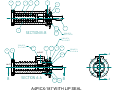
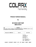
PRODUCT SERVICE MANUAL
For
3432/094 (A4PICX-187/094)
WARNING
Imo General Installation Operation, Maintenance, and Troubleshooting
Manual, (No. SRM00046), along with this manual and all other component
manuals supplied with these type units should be read thoroughly prior to
pump installation, start-up, operation, maintenance or troubleshooting.
MANUAL NO. SRM00124
Rev. 00
April, 2014
READ THIS ENTIRE PAGE BEFORE PROCEEDING
FOR THE SAFETY OF PERSONNEL AND TO PREVENT DAMAGE TO EQUIPMENT, THE
FOLLOWING NOMENCLATURE HAS BEEN USED IN THIS MANUAL:
DANGER
Failure to observe precautions noted in this box can result in severe bodily
injury or loss of life.
WARNING
Failure to observe precautions noted in this box can cause injury to personnel by
accidental contact with equipment or liquids. Protection should be provided by
user to prevent accidental contact.
CAUTION
ATTENTION
Failure to observe precautions noted in this box can cause damage or failure of
equipment.
Non-compliance of safety
instructions identified by
the following symbol
could affect safety for
persons:
Safety instructions where
electrical safety is
involved are identified by:
Safety instructions which
shall be considered for
reasons of safe operation
of pump and/or protection
of pump itself are marked
by the sign:
ATTENTION
CONTENTS
Safety and Table of Contents ..................................................................................................... A
A. General Instructions.............................................................................................................. 1
B. Introduction and Pump Model Identification........................................................................... 1
C. Description of Pump.............................................................................................................. 1
D. Ordering Instructions............................................................................................................. 1
E. Operating…………………….................................................................................................. 1
F. Parts List and Torque Tables ................................................................................................ 2
G. Inspection ............................................................................................................................. 2
H. Pump Maintenance (Disassembly and Assembly Instructions).............................................. 2 - 4
I. Pump Assembly Drawing ...................................................................................................... 5
ATTENTION
If operation of this pump is critical to your business, we strongly recommend
you keep a spare pump or major repair kit in stock at all times. As a minimum,
a minor repair kit (O-rings, gaskets, shaft seal and bearings) should be kept in
stock so pump refurbishment after internal inspection can be accomplished.
A
A. GENERAL INSTRUCTIONS
Instructions found herein cover disassembly, assembly and parts identification of the A4PICX187/094 pump.
NOTE: Individual contracts may have specific provisions that vary from this manual. For further
detailed information and technical assistance to questions not answered by these manuals, please
refer to Imo Pump, Technical/Customer Service Department, at (704) 289-6511.
This manual cannot possibly cover every situation connected with installation, operation, inspection,
and maintenance of equipment supplied. Every effort was made to prepare text of manual so that
engineering and design data is transformed into most easily understood wording. Imo Pump assumes
personnel assigned to operate and maintain supplied equipment and apply this instruction manual have
sufficient technical knowledge and experience to apply sound safety and operational practices which
may not be otherwise covered by this manual.
WARNING
If installation, operation and maintenance instructions are not correctly and strictly followed and observed,
injury to personnel or serious damage to pump could result. Imo Pump cannot accept responsibility for
unsatisfactory performance or damage resulting from failure to comply with instructions.
B. INTRODUCTION
This instruction manual covers the A4PICX-187/094 Imo pump. This pump has been designed with a lip
seal for use in Solar lube oil systems. Model of each pump is identified on pump nameplate.
Definitions of model designators are identified in Figure 1.
A
4PIC X 187
/ 094
Special Suffix
Rotor Size: 187
Design Modification
Series
LIP Seal Design
Figure 1 – Definition of Model Designators
C. DESCRIPTION OF PUMP
A4PICX-187/094 pump is positive displacement, rotary screw pumps consisting of a precision bored
housing that encloses a driven screw (power rotor) and two intermeshing following screws (idler rotors).
These screws when rotating form a succession of closures or cavities. As they rotate, fluid is moved
axially from inlet to outlet port in a continuous, uniform flow with minimum fluid pulsation and pump
noise. Pump contains a lip seal.
D. ORDERING INSTRUCTIONS
To order a replacement pump, contact Imo service representative with pump model number, serial
number and manufactured date. This information can be found on pump’s nameplate.
E. OPERATION
E.1 LIQUID LIMITATIONS
Never operate with thin liquids such as solvents or water. Pump is designed for liquids
having general characteristics of oil.
1
E.2 OPERATING LIMITATIONS
CAUTION
ATTENTION
Operating conditions, such as speed, fluid viscosity, temperature inlet pressure, discharge
pressure, filtration, duty cycle, drive type, mounting, etc., are interrelated. Due to these
variable conditions, specific application limits may be different from operational limitations.
Equipment must not be operated without verifying system’s operating requirements are
within pump’s capabilities.
Under no circumstances are operating limits (specified in Table 1 below) to be exceeded
without specific approval from Imo Pump.
Table 1 – Pump Operating and Structural Limits
MAXIMUM SPEED .............. 3600 RPM
VISCOSITY ......................... 60 SSU (10.3 Cst) Minimum, if over 5000 SSU (1079 cSt) contact Imo Pump
TEMPERATURE ................. 0° to 180° F (-18° to 82° C) Maximum
INLET PRESSURES............ A4PICX-187/094 pump is submerged in a slightly pressurized reservoir
DRIVE ................................. Direct drive only
FILTRATION ...................... Always use inlet strainer
MOUNTING ........................ Flange mounted only
F. PARTS LIST AND TORQUE TABLES
Table 2 – Pump Parts List
Item
Qty.
Part Description
1
1
Power Rotor
2
1
Key
3
1
Retaining Ring
4
1
Retaining Ring
5
1
Bearing
6
1
Inboard Cover
7
2
Washer
8
1
Rotor Housing
9
4
Lock Washers
10
2
Socket Head Capscrews
11
2
Idlers
Items marked with * are seal kit items
Item
12
15
17
20
21
22
23
24
25*
26*
Qty.
1
1
4
1
2
1
1
4
1
1
Part Description
Spacer
Strainer
Hex Capscrews
Adapter Fitting
Drive Screws
Name Plate
Seal Retainer
Socket Head Capscrew
O-ring
Lip Seal
G. INSPECTION
Intervals for inspection and replacement of worn parts varies with properties of pumped liquid and
can only be determined by experience. All parts of A4SICX-187/094 pump are lubricated by the
pumped fluids. Pumping liquid which contains abrasive materials or liquid that is corrosive will
significantly reduce service life and call for shorter service intervals. A worn pump will be
noticeable by excessive vibration, noise, reduction in flow or reduction in pressure.
H. PUMP MAINTENANCE
WARNING
Failure to observe precautions while installing, inspecting, and maintaining the pump can
cause injury to personnel from accidental handling, e.g.: Liquids that may harm skin or clothing,
fire hazard risks from flammable liquids, or injury from high pressure fluid jets.
2
DANGER
Before working on equipment, be sure power to equipment is disconnected and locked-out.
H.1 GENERAL COMMENTS
•
•
Part number identifiers (IDPs) contained within parenthesis such as (8) refer to circled
umbers shown on Assembly Drawing.
Close all pump line valves before working on pump.
H.2 TOOLS REQUIRED
Procedures described in this manual require common mechanics hand tools, a torque
wrench and a suitable lifting device (such as) slings, straps, etc.
H.3 PUMP DISASSEMBLY
CAUTION
ATTENTION
Fluid leakage from dis-assembly of pump ma y make floor slippery and cause
personal injury.
NOTE: The 4PIC pumps incorporate highly finished precision parts that must be handled carefully to
avoid damage to critical machined surfaces. Parts removed should be tagged for identification and their
exact positions in pump carefully noted so that new parts, or removed parts, are properly replaced.
1. If lip seal only is to be replaced, remove key (2) from shaft (1), remove seal retainer (23) by
removing socket head capscrews (24) and then remove lip seal (26) and O-ring (25) from seal
retainer and discard. See steps 7 and 8 on page 4 of assembly instructions for reinstallation of lip
seal (26).
2. If rest of pump is to be disassembled, proceed below.
3. Remove pump from driver by removing bolts (17) and washers (9). Place pump on workbench.
4. Remove strainer retaining ring (4) and strainer (15).
5. Place pump on end (suction side down) on a solid flat surface and remove capscrews (10)
6. Remove front cover and rotor set as a sub-assembly from housing (8) by lifting front cover (6)
with power rotor (1), idler rotors (11), ball bearing (5), supporting washer (12) and retaining ring
(3) from housing (8)
CAUTION
ATTENTION
During removal of front cover assembly, to prevent idlers (11) damage, hold idler
rotors (11) against power rotor (1) until sub-assembly is placed on work bench. At
that time, Idler rotor (11) can be disengaged from power rotor (1).
7. Disassembly front cover assembly by remove Retaining ring (3) and spacer (12) from front cover
(6). Then slide front cover off power rotor (1).
8. Remove ball bearing (5) from power rotor (1).
NOTE: Ball bearing (5) should be replaced if it is pressed off power rotor.
3
H.4 PUMP REASSEMBLY
NOTE: Prior to pump assembly, all parts should be cleaned and inspected for nicks, burrs or gouges.
When ready for assembly, wipe all parts, including bolts, with SAE 30 lubricating oil.
1. Install bearing (5) onto power rotor (1) either with a press or by heating.
CAUTION
ATTENTION
To prevent damage to bearing, press only on bearing inner race when installing
bearing. If bearing is being heated for installation, heat to 180°F - 200°F, for
installation.
2. Install spacer (12) onto power rotor against inner race of bearing (5) and then install retaining ring
(3) into groove on power rotor (1).
3. Slide front cover (6) onto power rotor (1), until bearing (5) is seated in bearing bore of cover (6).
4. Place pump on end (suction side down) on a solid flat surface for next step.
CAUTION
ATTENTION
To prevent idlers from disengaging from power rotor during next step, it is important to
hold idler rotors against power rotor until entire sub-assembly is positioned with
a minimum of rotor set length into housing.
5. Carefully mesh idler rotors (11) in proper position axially onto power rotor (5) and while holding
idlers in that position carefully lift rotor set and front cover sub-assembly and install into housing
(8). When rotor set is approximately 50% of its length into housing (8), you can release idler
rotors (11) and continue installation until front cover (6) is firmly seated on locating diameter of
housing (8).
6. Install cap screws (10) and torque per value on assembly drawing.
7. Install lip seal (26) and O-ring (25) in seal cover (23). Be sure open side of lip seal (26) is facing
O-ring (25) side of seal cover (23).
8. Grease lip seal (23) and O-ring (25) and install seal cover (23) with lip seal (23) and O-ring (25)
onto shaft (1). Be careful not to turn lip of lip seal (23) inside out during installation.
9. Install inlet strainer (15) and retaining ring (4) into housing (8).
10. If adapter (20) was removed, screw into place on housing (8) and torque to required value on
assembly drawing.
NOTE: Pump should rotate free and smooth 360° of rotation.
11. Install pump onto bracket with lock washers (4) and bolts (17) and torque bolts (17) to value on assembly
drawing.
4
15
4
8
1
11
5
12
3
11
2
17
SECTION B-B
9
TORQUE TO
100 u 5 LB IN
TORQUE TO
35 u 2 LB FT
TORQUE TO
75 u 7 LB FT
22
20
6
10
7
23
21
OUTLET
TORQUE TO
50 u 2 LB IN
24
A
INLET
B
SECTION A-A
25
26
B
A4PICX-187 WITH LIP SEAL
A