1
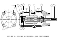
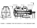
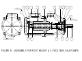
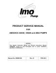
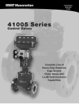
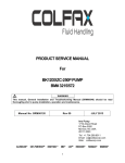
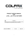
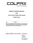
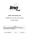
PRODUCT SERVICE MANUAL
For
3E-187/200 SERIES PUMPS
WARNING
The Imo General Installation Operation, Maintenance, and Troubleshooting
Manual, (No. SRM00046), along with this manual and all other component
manuals supplied with these type units should be read thoroughly prior to pump
installation, start-up, operation, maintenance or troubleshooting.
MANUAL NO. SRM00019
Rev. 05 (14-0129)
MARCH, 2014
READ THIS ENTIRE PAGE BEFORE PROCEEDING
FOR SAFETY OF PERSONNEL AND TO PREVENT DAMAGE TO THE EQUIPMENT, THE
FOLLOWING NOMENCLATURE HAS BEEN USED IN THIS MANUAL:
DANGER
Failure to observe precautions noted in this box can result in severe bodily injury or loss of life.
WARNING
Failure to observe precautions noted in this box can cause injury to personnel by accidental
contact with equipment or liquids. Protection should be provided by user to prevent accidental
contact.
CAUTION
ATTENTION
Failure to observe precautions noted in this box can cause damage or failure of equipment.
Noncompliance of safety Safety instructions where
instructions identified by the electrical safety is involved
following symbol could affect are identified by:
safety for persons:
Safety instructions which shall
be considered for reasons of
safe operation of the pump
and/or protection of the pump
itself are marked by the sign:
ATTENTION
CONTENTS
Safety and Table of Contents ..................................................................................................... A
General Instructions ................................................................................................................... 1
Pump Model Identification .......................................................................................................... 1
Description of the Equipment ..................................................................................................... 2
Ordering Instructions .................................................................................................................. 2
Operation ................................................................................................................................... 2
Spare Parts and Kits .................................................................................................................. 3
Inspection of Parts...................................................................................................................... 4
Pump Maintenance .................................................................................................................... 4
Pump Disassembly Instructions.................................................................................................. 4
Pump Assembly Instructions ...................................................................................................... 7
Troubleshooting ......................................................................................................................... 7
Pump Assembly Drawings................................................................................................... 8 - 12
ATTENTION
If operation of this pump is critical to your business, we strongly
recommend you keep a spare pump or major repair kit in stock at all times.
As a minimum, a minor repair kit (o-rings, gaskets, shaft seal and bearings)
should be kept in stock so pump refurbishment after internal inspection can
be accomplished.
A
A. GENERAL INSTRUCTIONS
Instructions found herein cover disassembly, assembly and parts identification of 3E-187 & 200
Series, Imo pumps.
NOTE: Individual contracts may have specific provision that vary from this manual. Should
questions arise which may not be answered by these instructions, refer to the Imo
General Installation Operation, Maintenance, and Troubleshooting Manual, (No.
SRM00046). For further detailed information and technical assistance please refer to Imo
Pump, Technical Service Department at (704) 289-6511.
This manual cannot possibly cover every situation connected with installation, operation, inspection
and maintenance of equipment supplied. Every effort was made to prepare text of manual so that
engineering and design data is transformed into the most easily understood wording. Imo Pump
must assume the personnel assigned to operate and maintain supplied equipment and apply this
instruction manual have sufficient technical knowledge and are experienced to apply sound safety
and operational practices which may not be otherwise covered by this manual.
WARNING
If installation, operation and maintenance instructions are not correctly and strictly followed and
observed, injury to personnel or serious damage to pump could result. Imo Pump cannot accept
responsibility for unsatisfactory performance or damage resulting from failure to comply with instructions.
B. INTRODUCTION
Instruction manual covers series 3E-187 & 200 Imo Pumps. Series of pumps has been designed
for general use in lubricating, seal and distillate fuel oil applications. The size and construction of
each pump is identified in model number on the pump nameplate. Definitions of model designators
are identified in Figure 1.
Model Designator Definitions
1
C. DESCRIPTION OF EQUIPMENT
3E-187/200 Series pumps are positive displacement, rotary screw pumps with a precision bored
housing that encloses a drive screw (power rotor) and two intermeshing driven screws (idler
rotors). These screws, when rotating, form a succession of closures or cavities. As they rotate,
fluid is moved axially from inlet to outlet in a continuous, uniform flow with minimum fluid pulsation
and pump noise.
D. ORDERING INSTRUCTIONS
All correspondence pertaining to renewal parts for equipment must refer to instruction manual
number and should be addressed to nearest Imo representative. Handling of renewal orders will be
greatly facilitated if following directions are carefully observed:
1. Give number of instruction manual with revision level and date.
2. Give model number of pump for which part is desired. Number appears on nameplate.
3. Repair parts are sold in either a major or minor kit form for the pump. Parts are designated by
IDP numbers and names and are shown on assembly drawings and as listed in Table 2 in this
instruction manual.
E. OPERATION
E-1 – LIQUID LIMITATIONS – Never operate with water. Pump is designed for liquids having
general characteristics of oil.
E-2 – OPERATING LIMITS
CAUTION
ATTENTION
Operating conditions, such as speed, fluid viscosity, temperature inlet pressure, discharge
pressure, filtration, duty cycle, drive type, mounting, etc., are interrelated. Due to these
variable conditions, specific application limits may be different from that of operational
limitations. Equipment must not be operated without verifying system’s operating requirements
are within pump’s capabilities.
Table 1 – Pump Operating and Structural Limits
Maximum Speed:
Type B & H Seals = 4000 RPM for 187 size, 3800 RPM for 200 size.
Type N and J Seals = 3500 RPM
Type I = 4250 RPM for 187 size and 4000 RPM for 200 size
Viscosity:
Type B & I = 33 to 3000 SSU (2.1 to 650 CST)
Type H = 33 to 15000 SSU (2.1 to 5000 CST)
Type N and J = 60-5000 SSU (10 to 1080 CST)
Temperature Range:
Type B = 0 to 180°F (-18 to 82°C)
Type H, I and N = 0-250°F (-18 to 121°C)
Maximum Inlet Pressure:
Type B, H and I = 75 psig max.
Type N and J = 250 Psig max,
Maximum Discharge Pressure:
Type B, H and I = 150 psig max.
Type N = 350 Psig Max. (Provided differential pressure does not exceed 150 psid)
Drive ........................................................................................................................................................... Direct Only
Filtration............................................................................................... See General Installation Manual, SRM00046
Mounting .......................................................................................................Foot or Flange Mounted in Any Attitude
Shaft Rotation ........................................................... Available in CW or CCW versions (Pump is not bi-rotational).
2
F. PARTS LIST TABLE – TABLE 2
IDP
1XX
2
3
4
6
7XX
8XX
11X
12
13
QTY
1
1
4
1
4
1
2
1
1
1
DESCRIPTION
Housing
Inlet Head
Main Hex Capscrews
Inboard Cover
Retainer Capscrews
Power Rotor
Idler Rotor
Ball Bearing
Bearing Retainer
Key
IDP
15X
16X
26X
32XX
33
34
35
93
96X
QTY
2
1
1
1
2
2
2
1
1
DESCRIPTION
Retaining Ring
Seal
O-ring
Thrust Plate
Thrust Spacer
Thrust Hex Capscrews
Lock Washer
Seal Seat Adapter
Seal Seat Adapter O-Ring
X = Minor Repair Kit Item
XX = Major Repair Kit Item
G. INSPECTION
Interval for inspection and replacement of worn parts varies with properties of pumped liquid
and can only be determined by experience. All internal parts of 3E Series pumps are lubricated
by pumped fluids. Pumping liquid which contains abrasive materials or liquid that is corrosive
will significantly reduce service life and call for shorter service intervals. A worn pump will be
noticeable by excessive vibration, noise, reduction in flow output and/or reduction in system
pressure.
H. PUMP MAINTENANCE
WARNING
Failure to observe precautions while installing, inspecting, and maintaining the pump can
cause injury to personnel from accidental handling, e.g.: Liquids that may harm skin or
clothing, fire hazard risks from flammable liquids, or injury from high pressure fluid jets.
DANGER
BEFORE working on equipment, be sure all power to equipment is disconnected and
locked-out.
H-1 – GENERAL COMMENTS
Part number identifiers (IDPs) contained in Table 2 and shown within parenthesis such as (8) refer
to circled numbers shown on the assembly drawings, Figures 3 through 5.
H-2 – TOOLS REQUIRED
Procedures described in this manual require common mechanics hand tools, an arbor press, a
torque wrench and a suitable lifting device such as a sling for smaller pumps or a strap for larger
models.
H-3 – PUMP DISASSEMBLY –
CAUTION
ATTENTION
Fluid leakage from disassembly of pump may make floor slippery and
cause personal injury.
3
The following steps are required before starting any maintenance action:
a)
b)
c)
d)
e)
f)
De-energize and lock out power to driver and tag power control box “WARNING - Out of Service”.
Close all inlet and outlet valves and tag valves “WARNING - Out of Service”.
Vent pressure from pump and drain pumping liquid.
Remove pipe fittings/flanges at pump inlet and outlet openings.
Remove bolts holding pump to its mounting.
Remove coupling and key (13) from power rotor (7) shaft and locate pump on suitable
workbench.
NOTE: The 3E Series pumps incorporate highly finished precision parts that must be handled
carefully to avoid damage to critical machined surfaces. Parts removed should be tagged
for identification and their exact positions in the pump carefully noted so that new parts, or
removed parts can be properly replaced.
1. If pump is seal-less version (3EIC(S), use assembly drawing figure 3 and skip to step 4 for
disassembly, if not proceed below using assembly figures 4 or 5 whichever is applicable.
2. Remove hex capscrews (6) and bearing retainer (12) from inboard cover (4) and then
remove power rotor (7) assembly from inboard cover (4). Power rotor (7) assembly includes
seal (16), seal seat adapter (93) with its O-ring (96), bearing (11) and snap rings (15).
3. Disassembly power rotor as follows using appropriate assembly and seal drawings, figures
1 and 2:
a. Remove retaining ring (15) nearest power rotor keyway.
b. Using a bearing puller remove the bearing (11) from power rotor (7). During the
removal of the bearing support the power rotor to prevent the assembly from falling
when the bearing comes off the bearing fit of the power rotor (7).
An optional method for removing the bearing is via the use of an arbor press. To do so
involves sliding two small pieces of key stock through the slots between the bearing
(11) and bearing spacer/seal seat adapter assembly (93). Place the power rotor (7) in
the arbor press with the two pieces of key stock being used to support the assembly
and assume the pressure while pressing the power rotor (7) through the bearing (11).
When pressing the power rotor through the bearing take care that the key stock does
not contact the inner retaining rings (15) there by damaging the retaining rings and
retaining grooves on the power rotor(7). During the removal of the bearing support the
power rotor (7) to prevent the assembly from falling when the bearing (11) comes off
the bearing fit of the power rotor (7).
c. Remove inner retaining ring (15).
CAUTION
ATTENTION
Do not drop power rotor (7) as it is pressed from bearing (11)
d. Slide spacer/seal seat adapter sub assembly (93) with O-ring (96) and seal (016)
stationary seat from power rotor (7). Remove seal (16) stationary seat and O-ring from
spacer/seal seat adapter sub assembly (93). Remove seal (16) rotating seat from
power rotor (7).
4
NOTE: If seal (16) is multi-spring or balanced multi-spring type, loosen the set screws
that secure the rotating portion of the seal to the power rotor (7). Using a twisting
motion remove the rotating half of the seal from the power rotor (7). If the seal is
the rubber bellows type remove the rotating portion of the seal using a twisting
motion as this portion of the seal may be stuck to the power rotor (7).
e. If seal only is to be replaced, disassembly is complete. Proceed to step 6 in H4 for
reassembly of power rotor and pump. Otherwise proceed to step 4 below.
4. Remove inlet (2) and housing (1) with pin from inboard cover (4) by removing hex
capscrews (3). Remove O-ring (26) from inboard cover (4).
5. Remove thrust plate (32) and spacers (33) from housing (1) by removing hex capscrews
(34) and washers (35).
6. Remove idlers (8) from housing (1). (For 3EIC(S) version also remove power rotor (7) from
housing (1)).
H4. PUMP REASSEMBLY
General: Prior to reassembly, inspect, clean and coat all internal parts with fluid being
pumped. Rotate power rotor (7) frequently during assembly to ensure freedom of rotation. It
is recommended that all O-rings (96, 26), seal (16) and bearing (11) be replaced whenever
they are removed from their installed position.
1. Assemble washers (35), thrust plate (32) and spacers (33) onto hex capscrews (34). Install
hex capscrews (34) into housing (1). Torque capscrews (34) to value on assembly drawing.
2. Install idlers (8) into housing (1) from discharge end of pump. Ensure that end of idlers (8)
with root diameter taper goes toward inlet (thrust) end of housing (1).
3. If pump is 3EIC version, install power rotor (7) into housing
4. Install O-ring (26) into groove in front cover (4) and housing (1) assembly with installed
idlers (8) (and power rotor if 3EIC) and thrust plate (32) into front cover (4) using hex
capscrews (3). Be sure pin in housing (1) engages pin hole in inboard cover (4).
CAUTION
ATTENTION
Be sure idlers (8) (and power rotor (7) if 3EIC pump) do not drop out of housing (1)
when installing housing (1) on inboard cover (4).
5. If reassembling 3EIC pump, assembly is complete. Otherwise proceed below.
CAUTION
ATTENTION
The below steps are critical in preventing damage to the mechanical seals during
assembly. If the below steps are not carefully followed mechanical seal leakage
may occur!
5
6.
Assemble power rotor (7) as below:
a. If seal is elastomeric bellows type, (Fig. 1), apply light film of oil to bellows bore on the
rotating portion of mechanical seal. Apply a light film of oil on the seal fit area of the
power rotor. Caution must be taken when sliding rotating assembly over snap ring
grooves. Check the snap ring grooves to ensure no burrs are present that might cause
damage to the rotating assembly of the seal. Install rotating assembly on power rotor
(7) using a twisting motion. Clean carbon face of the rotating portion of the seal with
alcohol and a lint free cloth. Apply light film of clean lubricating oil to carbon face.
b. If seal is multi-spring type, (Fig. 2), apply light film of oil to rotating seat O-ring and on
the seal fit area of the power rotor (7). Caution must be taken when sliding rotating
assembly over snap ring grooves. Check the snap ring grooves to ensure no burrs are
present that might cause damage to the O-ring. Install rotating assembly on power rotor
(7) shaft using a twisting motion. Clean carbon face of the rotating portion of the seal
with alcohol and a lint free cloth. Apply light film of clean lubricating oil to carbon face.
c. Install O-ring on stationary seal face (Fig 1 and 2). Install stationary seal face into bore of
seal seat adapter assembly (93) by pressing it into position with fingers (do not touch
seal face with any tools). When installing the stationary seal face into seal seat adapter
assembly (93), ensure that the slot on the back of the stationary seal face assembly is
perfectly aligned with the anti-rotation pin located in the face of the seal seat adapter
assembly (93). After assembly is complete ensure that the stationary seal face
assembly bottoms out at the face of the seal seat adapter assembly (93) and the antirotation pin slot is mated with the anti-rotation pin in the seal seat adapter assembly
(93).
6
d. Clean the stationary seal face with alcohol and a lint free cloth. Apply a light coat of oil
to the seal face. Install seal seat adapter assembly (93) with installed stationary seat
onto power rotor with face of stationary seal up against face of rotating seat seal face.
e. Install snap rings (15) in inner snap ring grooves of power rotor (7) next o seal seat
adapter assembly (93).
f.
Support power rotor (7) on suction end and press ball bearing (11) on power rotor (7),
pressing on inner race of bearing (11) only until it seats against inner snap ring (15).
Install outer snap ring (15) nearest shaft (7) keyway. If mechanical seal is a MultiSpring Type Seal, (Fig 2 Only) tighten set screws in rotating half of the mechanical
seal.
7. Install O-ring (96) on seal seat adapter assembly (93). Install assembled power rotor (7)
into inboard cover (4). Power rotor should be turned while installing to mesh with idlers
(8).
8. Install bearing cover (12) with hex capscrews (6), and torque to value on assembly
drawing.
I.
TROUBLESHOOTING
For assistance with troubleshooting see General Instruction Manual, SRM00046.
J. FIELD AND FACTORY SERVICE AND PARTS
Imo Pump maintains a staff of trained service personnel that can provide pump installation,
pump start-up, maintenance/overhaul and troubleshooting supervision as well as installation
and maintenance training.
Our factories provide maintenance as well as overhaul and test facilities in event user prefers
to return pumps for inspection or overhaul. Pumps that have been factory-overhauled are
normally tested and warranted “as-new” for a period of one year from date of shipment. For
either field service or factory overhaul assistance, contact your local Imo Sales Office or
representative at Technical/Customer Service Department in Monroe, NC, USA.
Most pumps have repair kits available. Minor Repair Kits are used to repair leaking seals, bad
bearings and/or for re-assembly after pump tear-down. They include (as applicable) pump
shaft seals, all gaskets/O-rings and bearings. Major Repair Kits are sufficient to rebuild
completely worn-out pumps to “as-new” condition. They include all parts found in Minor Repair
Kits plus all major internal parts subject to wear. Since kits have all necessary parts, it is
preferred that they be purchased rather than selecting individual parts. When parts are
individually selected from Parts List, some needed components are often overlooked. In
addition, mixing worn or used parts with new parts risks rapid wear and shortened service life
from new parts.
7
TORQUE TO
20 ± 2 LBS-FT
35
33
2
34
3
TORQUE TO
45 ± 5 LB-FT
1
INLET
32
4
26
OUTLET
8
FIGURE 3 - ASSEMBLY FOR SEAL-LESS (3EIC) PUMPS
13
7
TORQUE TO
40 ± 5 LBS-IN
35
33
2
26
96
11
6
12
OUTLET
INLET
TORQUE TO
20 ± 2 LBS-FT
4
34
3
TORQUE TO
45 ± 5 LB-FT
32
8
1
16
93
15
13
7
FIGURE 4 - ASSEMBLY FOR FOOT MOUNT & C-FACE (3EB,3EH) PUMPS
35
33
1
2
26
4
93
96
11
12
TORQUE TO
20 ± 2 LBS-FT
INLET
34
OUTLET
6
TORQUE TO
40 ± 5 LBS-IN
3
TORQUE TO
45 ± 5 LB-FT
32
8
16
15
13
7
FIGURE 5 - ASSEMBLY FOR FOOT MOUNT & C-FACE (3EN, 3EJ) PUMPS
35
33
2
1
4
26
11
93
12
TORQUE TO
20 ± 2 LBS-FT
INLET
34
OUTLET
6
TORQUE TO
40 ± 5 LBS-IN
32
3
8
16
TORQUE TO
45 ± 5 LB-FT
NOTES:
1. STEEL CASE PUMPS TO USE SAE 4-BOLT FITTINGS.
IRON CASE PUMPS WILL BE PIPE TAP INLET AND OUTLET.
FIGURE 6. C-FACE ASSEMBLY SD-5571
96
15
13
7
Imo Pump
1710 Airport Road
PO Box 5020
Monroe, NC USA
28111.5020
Tel: +1.704.289.6511
Toll: +1.877.853.7867
Email: [email protected]
Web: colfaxcorp.com
© 2012 Colfax Fluid Handling all rights reserved.