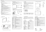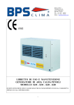
1
EXTER™-series Operator Terminals
Service and Maintenance Manual
MA00757A 2006-07
English
Foreword
Service and Maintenance Manual for EXTER Operator Terminals
Foreword
This manual contains detailed information about the EXTER series operator
terminals, including descriptions of various actions that can be carried out in order
to maintain or update the operator terminal hardware and software.
The manual is intended for persons that should be able to carry out basic
maintenance and replace common parts in an EXTER-series operator terminal.
The manual assumes that the most recent versions of the system program (firmware)
and configuration tool are used.
Please see the Information Designer Reference Manual (MA00749B) for a description of the configuration tool and the installation manuals for information regarding
installation.
Function-based descriptions are available in the User’s Guide (MA00750A).
© Beijer Electronics AB, MA00757A, 2006-07
The information in this document is subject to change without notice and is provided as available at the time of
printing. Beijer Electronics reserves the right to change any information without updating this publication. Beijer
Electronics assumes no responsibility for any errors that may appear in this document.
All examples in this document are only intended to improve understanding of the functionality and handling of
the equipment. Beijer Electronics AB cannot assume any liability if these examples are used in real applications.
In view of the wide range of applications for this software, users must acquire sufficient knowledge themselves in
order to ensure that it is correctly used in their specific application. Persons responsible for the application and
the equipment must themselves ensure that each application is in compliance with all relevant requirements,
standards and legislation in respect to configuration and safety.
Beijer Electronics AB will accept no liability for any damage incurred during the installation or use of equipment
mentioned in this document.
Beijer Electronics AB prohibits all modification, changes or conversion of the equipment.
Beijer Electronics, MA00757A
Contents
Contents
1 Safety Precautions ..........................................................................................5
2 Introduction...................................................................................................7
2.1
General ............................................................................................... 7
2.2
Maintenance ..................................................................................... 10
2.3
Service and Repairs ........................................................................... 10
2.4
Dismantling and Scrapping............................................................... 10
2.5
Contact and Support......................................................................... 11
3 Hardware .....................................................................................................13
3.1
General Information about Hardware ............................................... 13
3.2
Hardware Tests ................................................................................. 13
3.3
3.3.1
3.3.2
Hardware Specification ..................................................................... 13
Keyboard Operated Terminals .......................................................... 13
Touch Screen Operated Terminals.................................................... 16
3.4
Approvals and Enclosure Classes ....................................................... 18
3.5
Functionality Specification................................................................ 19
3.6
3.6.1
Additional Hardware ........................................................................ 20
Memory Card ................................................................................... 20
3.7
3.7.1
3.7.2
3.7.3
3.7.4
3.7.5
3.7.6
3.7.7
3.7.8
3.7.9
3.7.10
Hardware Replacement ..................................................................... 22
Mode Switches.................................................................................. 22
Cables ............................................................................................... 23
Replacing the Rear Cover.................................................................. 24
Replacing the Display/Display Cable ................................................ 26
Self-test of the Display ...................................................................... 34
Calibrate the Touch Screen............................................................... 34
Replacing the Complete Front .......................................................... 35
Replacing the Battery ........................................................................ 37
Replacing the Backlight .................................................................... 39
Available Spare Parts ......................................................................... 41
3.8
Hardware Self Test............................................................................ 44
3.9
Fault Tracing .................................................................................... 45
4 Software .......................................................................................................47
4.1
4.1.1
General Information about Software ................................................. 47
Software Products ............................................................................. 47
4.2
4.2.1
4.2.2
4.2.3
4.2.4
Update Software ............................................................................... 48
Information Designer........................................................................ 48
Remote Access Viewer....................................................................... 48
Image Loader .................................................................................... 48
System Program ................................................................................ 49
Beijer Electronics, MA00757A
Contents
5 Environmental Aspects ................................................................................ 51
5.1
General Environmental Aspects.........................................................51
5.2
5.2.1
5.2.2
Environmental Impact of the Operator Terminals.............................51
Mechanical Components...................................................................51
Electronics.........................................................................................51
5.3
Recycling...........................................................................................52
5.4
Environmental Impact Report ...........................................................52
Beijer Electronics, MA00757A
Safety Precautions
1
Safety Precautions
The person responsible for maintenance of the operator terminal must read and
understand the installation manual and the safety precautions.
– Only qualified personnel may install, operate or maintain the operator terminal.
– Avoid exposing the operator terminal to the following:
– strong magnetic fields
– direct sunlight
– large, sudden temperature changes
– high humidity (>85%)
– high explosive risks
– Never allow fluids, lose metal filings, or wiring debris to enter the operator
terminal. They may cause fire or electric shocks.
– Storing the operator terminal where the temperature is lower or higher than
recommended in this manual can cause the display liquid (in LCD) to congeal or
become isotopic.
– The display liquid (in LCD) contains a powerful irritant. In case of skin contact,
wash immediately with plenty of water. In case of eye contact, hold the eye open,
flush with plenty of water, and seek medical attention.
– The supplier is not responsible for modified, altered, or reconstructed operator
terminal.
– Only use parts and accessories manufactured according to the supplier’s
specifications.
– Make sure the service area has good ESD protection.
– During operation, the CCFL and DC/AC inverter sections are live with high
voltages that can cause electric shock.
– Only use current-limited power supplies during service. The current should never
exceed the rated maximum current.
– Never apply a voltage outside the specified input voltage range. This can cause
permanent damage and deteriorate EMC protection.
– Make sure the correct versions of the documentation and service instructions are
used during service or maintenance.
– Only upgrade hardware if such instructions are found in the service manual or if
sanctioned by the supplier.
– Replacing the battery incorrectly may result in explosion. Only use batteries
recommended by the supplier.
Beijer Electronics, MA00757A
5
Safety Precautions
6
Beijer Electronics, MA00757A
Introduction
2
Introduction
This manual describes how to maintain EXTER series operator terminals.
The functions available in the configuration tool depend on which operator
terminal model is used. The manual is divided into the following sections:
– Safety Precautions
– Introduction
– Hardware
– Software
– Environmental Aspects
2.1
General
The HMI range offers four different sized keypad-operated models and five touch
screen models. The different operator terminals are listed in the table below:
Operator
Terminal
Description
Drawings
EXTER K30
(also referred to
as BEPP K30)
240 x 64 pixels, display with keypad
Outline drawing
Panel cut-out
Text strip
EXTER K60c
(also referred to
as BEPP K60)
5.7" display with keypad
Outline drawing
Panel cut-out
Text strip
Beijer Electronics, MA00757A
7
Introduction
Operator
Terminal
8
Description
Drawings
EXTER K70
(also referred to
as BEPP 64K)
6.5" display with keypad
Outline drawing
Panel cut-out
Text strip
EXTER K100
(also referred to
as BEPP 104K)
10.4" display with keypad
Outline drawing
Panel cut-out
Text strip
EXTER T40/
EXTER T40m
(also referred to
as BEPP T40)
3.5" touch screen display
Outline drawing
Panel cut-out
EXTER T60c/
EXTER T60m
(also referred to
as BEPP T60)
5.7" touch screen display
Outline drawing
Panel cut-out
Beijer Electronics, MA00757A
Introduction
Operator
Terminal
Description
Drawings
EXTER T70
(also referred to
as BEPP 64T)
6.5" touch screen display
Outline drawing
Panel cut-out
EXTER T100
(also referred to
as BEPP 104T)
10.4" touch screen display
Outline drawing
Panel cut-out
EXTER T150
(also referred to
as BEPP 150T)
15" touch screen display
Outline drawing
Panel cut-out
Beijer Electronics, MA00757A
9
Introduction
2.2
Maintenance
Carefully read the instructions before beginning maintenance on the operator
terminal.
– Only qualified personnel should carry out maintenance.
– The agreed warranty and license agreements apply.
– Any damage to the operator terminal caused by personnel invalidates the
warranty.
– Before carrying out any cleaning or maintenance operations, disconnect the
operator terminal from the power supply.
– Clean the display and surrounding front cover with a soft cloth and mild
detergent. Recommended cleaning fluids for the display are water and IPA
(Isopropyl Alcohol or Hexane).
– Replacing the battery incorrectly may result in explosion. Only use batteries recommended by the supplier.
– A 6-month warranty on all service parts is provided.
Maintenance personnel are permitted to carry out the following actions:
– Replacing the Rear Cover
– Replacing the Battery
– Replacing the Backlight
– Replacing the Complete Front
2.3
Service and Repairs
– Only accredited companies are permitted to perform service and repairs.
– If a non-accredited company conducts any kind of service or repair, the agreed
warranty will be invalidated.
– If training is required, contact the supplier.
– All maintenance should be performed in a 15-30 °C temperature range.
– Any damage to the operator terminal caused by personnel invalidates the
warranty.
– Contracts with customers supersede the information in this document.
2.4
Dismantling and Scrapping
– The operator terminal, or parts thereof, should be recycled according to local
regulations.
– The following components contain substances that might be hazardous to health
and the environment: lithium battery, electrolytic capacitor, display.
10
Beijer Electronics, MA00757A
Introduction
2.5
Contact and Support
If you want to report a fault or have a question about the operator terminals, please
contact your local supplier or fill out the form on the web site.
1. Enter the web site: www.hmi.beijerelectronics.com and select Support.
2. Select Contact Form in the menu. Make sure to provide information about type
number, serial number, environment and an installation description.
The form will be sent to the manufacturer’s help desk and they will answer your question or register your improvement/fault.
To ensure quick resolution, provide as many details as possible in your report.
Include the date and time when the problem occurred, a description of what you
were trying to do, the detailed steps you took that led up to the problem, and details
about any error messages received.
Beijer Electronics, MA00757A
11
Introduction
12
Beijer Electronics, MA00757A
Hardware
3
Hardware
This chapter describes how to maintain the EXTER operator terminal hardware. The
chapter includes general information, hardware tests and certificates, technical data,
a hardware replacement guide, and a fault tracing section.
3.1
General Information about Hardware
Before the operator terminals are approved for market introduction, they are
tested by independent authorities. The EXTER operator terminals are examined by
several authorities before being approved for market introduction. All operator terminals are designed to fulfill CE, UL, and other standards. The quality policy and
environmental policy place demands on all suppliers and subcontractors.
3.2
Hardware Tests
The manufacturer performs extensive hardware testing before an operator terminal
is approved. Some tests are performed by external testing companies, such as the
Swedish National Testing and Research Institute.
All operator terminals are submitted to testing before leaving the manufacturer.
3.3
Hardware Specification
3.3.1
Keyboard Operated Terminals
The tables below presents technical data for the keyboard operated terminals.
Technical Data
EXTER K30m
EXTER K60c
Front panel, W x H x D
202 x 187 x 6 mm
275 x 168 x 6 mm
Mounting depth
56.9 mm
(156.9 mm incl. clearance)
57.3 mm
(157.3 mm incl. clearance)
Keypad material
Membrane switch keypad with metal domes.
Overlay film of Autotex F157 with print on reverse side.
1 million operations.
Reverse side material
Powder-coated aluminum
Weight
0.875 kg
Serial port RS422/RS485
25-pin D-sub contact, chassis-mounted female with standard locking screws 4-40 UNC.
Serial port RS232C
9-pin D-sub contact, male with standard locking screws
4-40 UNC.
Ethernet
Shielded RJ 45 10/100 Mbit/s
USB
Host type A, max output current 500 mA.
Processor
312 MHz RISC CPU (Intel XScale).
Memory flash
32 MB (Intel StrataFlash).
Application memory: 12 MB (incl. fonts)
Memory RAM
64 MB
Memory Expansion
None
Buzzer
Yes
Beijer Electronics, MA00757A
1.11 kg
13
Hardware
Technical Data
EXTER K30m
EXTER K60c
Real time clock
±20 PPM + error because of ambient temperature and
supply voltage.
Total max error: 1 min/month at 25 °C.
Minimum life of the real time clock battery: 3 years.
Temperature coefficient: 0.004 ppm/°C2
Power consumption at
rated voltage
Normal: 0.15 A
Max.: 0.35 A
Normal: 0.3 A
Max.: 0.5 A
Display
FSTN-LCD, 240 x 64 pixels,
monochrome.
CSTN-LCD, 320 x 240 pixels,
64K color.
Display backlight
CCFL backlight lifetime at the ambient temp. of +25 °C:
>50,000 h
>60,000 h
With dimming
14
Active area of display,
WxH
127.0 x 33.8 mm
115.2 x 86.4 mm
Fuse
Internal DC fuse, 3.15 AT, 5 x 20 mm
Power supply
+24 V DC (20 - 30 V DC). 3-pin jack connection block.
CE: The power supply must conform with the requirements for SELV or PELV according to IEC 950 or IEC 742.
UL: The power supply must conform with the requirements for class II power supplies.
Ambient temperature
Vertical installation: 0 ° to +50 °C.
Horizontal installation: 0 ° to +40 °C.
Storage temperature
-20 ° to +70 °C.
Relative humidity
5 - 85% non-condensed.
Beijer Electronics, MA00757A
Hardware
Technical Data
EXTER K70
EXTER K100
Front panel, W x H x D
285 x 177 x 6 mm
382 x 252 x 6 mm
Mounting depth
56 mm
(156 mm incl. clearance)
58 mm
(158 mm incl. clearance)
Keypad material
Membrane switch keypad with metal domes.
Overlay film of Autotex F157 with print on reverse side.
1 million operations.
Reverse side material
Powder-coated aluminum
Weight
1.3 kg
Serial port RS422/RS485
25-pin D-sub contact, chassis-mounted female with
standard locking screws 4-40 UNC.
Serial port RS232C
9-pin D-sub contact, male with standard locking screws
4-40 UNC.
Ethernet
Shielded RJ 45 10/100 mbit/sec.
USB
Host type A, max output current 500 mA. Device type B.
Processor
416 MHz RISC CPU (Intel XScale).
Memory flash
32 MB (Intel StrataFlash).
Application memory: 12 MB (incl. fonts).
Memory RAM
64 MB
Memory Expansion
Compact Flash slot (CF slot type I and II) available for
adding optional cards for expansion of memory, data
back-up, data storage and transfer of data and projects.
Buzzer
Yes
Real time clock
±20 PPM + error because of ambient temperature and
supply voltage.
Total max error: 1 min/month at 25 °C.
Minimum life of the real time clock battery: 3 years.
Temperature coefficient: 0.004 ppm/°C2.
Power consumption at
rated voltage
Normal: 0.4 A
Max.: 0.9 A
Normal: 0.5 A
Max.: 1.0 A
Display
TFT-LCD, 640 x 480 pixels,
64K color.
TFT-LCD, 800 x 600 pixels,
64K color.
Display backlight
CCFL backlight lifetime at the ambient temp. of +25 °C:
50,000 h
2.3 kg
50,000 h
With dimming
Active area of display,
WxH
131.5 x 98.6 mm
Fuse
Internal DC fuse, 3.15 AT, 5 x 20 mm.
Power supply
+24 V DC (20 - 30 V DC). 3-pin jack connection block.
CE: The power supply must conform with the requirements for SELV or PELV according to IEC 950 or IEC 742.
UL: The power supply must conform with the
requirements for class II power supplies.
Ambient temperature
Vertical installation: 0 ° to +50 °C.
Horizontal installation: 0 ° to +40 °C.
Storage temperature
-20 ° to +70 °C.
Relative humidity
5 - 85% non-condensed.
Beijer Electronics, MA00757A
211.2 x 158.4 mm
15
Hardware
3.3.2
Touch Screen Operated Terminals
The tables below presents technical data for the touch screen operated terminals.
Technical Data
EXTER T40/T40m
EXTER T60c/T60m
Front panel, W x H x D
155.8 x 119 x 6 mm
201 x 152 x 6 mm
Mounting depth
56.8 mm
(156.8 mm incl. clearance)
56.8 mm
(156.8 mm incl. clearance)
Keypad material
Touch screen: Polyester on glass,
1 million finger touch operations.
Overlay: Autotex F207.
Reverse side material
Powder-coated aluminum
Weight
0.56 kg
Serial port RS422/RS485
25-pin D-sub contact, chassis-mounted female with standard locking screws 4-40 UNC.
Serial port RS232C
9-pin D-sub contact, male with standard locking screws
4-40 UNC.
Ethernet
Shielded RJ 45 10/100 mbit/sec.
USB
Host type A, max output current 500 mA.
Processor
312 MHz RISC CPU (Intel XScale).
Memory flash
32 MB (Intel StrataFlash).
Application memory: 12 MB (incl. fonts).
Memory RAM
64 MB
Memory Expansion
None
Buzzer
Yes
Real time clock
±20 PPM + error because of ambient temperature and
supply voltage.
Total max error: 1 min/month at 25 °C.
Minimum life of the real time clock battery: 3 years.
Temperature coefficient: 0.004 ppm/°C2.
Power consumption at
rated voltage
Normal: 0.15 A
Max.: 0.35 A
Normal: 0.4 A
Max.: 0.9 A
Display
TFT-LCD, 320 x 240 pixels
EXTER T40 64K color
EXTER T40m, 16 grey
scales
CSTN-LCD EXTER T60c
FSTN-LCD EXTER T60m
320 x 240 pixels
Display backlight
CCFL backlight lifetime at the ambient temp. of +25 °C:
>50,000 h
0.87 kg
>45,000 h
With dimming
16
Active area of display,
WxH
70.1 x 52.6 mm
115.2 x 86.4 mm
Fuse
Internal DC fuse, 3.15 AT, 5 x 20 mm.
Power supply
+24 V DC (20 - 30 V DC). 3-pin jack connection block.
CE: The power supply must conform with the requirements for SELV or PELV according to IEC 950 or IEC 742.
UL: The power supply must conform with the requirements for class II power supplies.
Ambient temperature
Vertical installation: 0 ° to +50 °C.
Horizontal installation: 0 ° to +40 °C.
Storage temperature
-20 ° to +70 °C.
Relative humidity
5 - 85% non-condensed.
Beijer Electronics, MA00757A
Hardware
Technical Data
EXTER T70
EXTER T100
EXTER T150
Front panel,
WxHxD
219 x 154 x 6 mm
302 x 228 x 6 mm
398 x 304 x 6 mm
Mounting depth
55 mm
(155 mm incl. clearance)
58 mm
(158 mm incl. clearance)
60 mm
(160 mm incl. clearance)
Keypad material
Touch screen: Polyester on glass,
1 million finger touch operations.
Overlay: Autotex F207.
Reverse side
material
Powder-coated aluminum
Weight
1.1 kg
Serial port RS422/
RS485
25-pin D-sub contact, chassis-mounted female with standard locking screws 4-40 UNC.
Serial port RS232C
9-pin D-sub contact, male with standard locking screws 4-40 UNC.
Ethernet
Shielded RJ 45 10/100 mbit/sec.
USB
Host type A, max output current 500 mA. Device type B.
Processor
416 MHz RISC CPU (Intel XScale).
Memory flash
32 MB (Intel StrataFlash).
Application memory: 12 MB (incl. fonts).
Memory RAM
64 MB
Memory Expansion
Compact Flash slot (CF slot type I and II) available for adding
optional cards for expansion of memory, data back-up, data storage and transfer of data and projects.
Buzzer
Yes
Real time clock
±20 PPM + error because of ambient temperature and supply voltage.
Total max error: 1 min/month at 25 °C.
Minimum life of the real time clock battery: 3 years.
Temperature coefficient: 0.004 ppm/°C2.
Power consumption at rated
voltage
Normal: 0.4 A
Max.: 0.9 A
Normal: 0.5 A
Max.: 1.0 A
Normal: 1.2 A
Max.: 1.7 A
Display
TFT-LCD
640 x 480 pixels,
64K color.
TFT-LCD
800 x 600 pixels,
64K color.
TFT-LCD
1024 x 768 pixels,
64K color.
Display backlight
CCFL backlight lifetime at the ambient temp. of +25 °C:
50,000 h
2.0 kg
3.7 kg
50,000 h
35,000 h
211.2 x 158.4 mm
304.1 x 228.1 mm
With dimming
Active area
of display, W x H
131.5 x 98.6 mm
Fuse
Internal DC fuse, 3.15 AT, 5 x 20 mm.
Power supply
+24 V DC (20 - 30 V DC). 3-pin jack connection block.
CE: The power supply must conform with the requirements for
SELV or PELV according to IEC 950 or IEC 742.
UL: The power supply must conform with the requirements for
class II power supplies.
Ambient
temperature
Vertical installation: 0 ° to +50 °C.
Horizontal installation: 0 ° to +40 °C.
Storage temperature
-20 ° to +70 °C.
Relative humidity
5 - 85% non-condensed.
Beijer Electronics, MA00757A
17
Hardware
3.4
Approvals and Enclosure Classes
EXTER K30m, EXTER K60c
EXTER T40/T40m
EXTER T60c/T60m
CE
EMC directive 89/336/EEC article 4.
The operator terminal conforms with the essential protection requirements in article 4 of the directive 89/336/EEC.
Noise tested according to EN610006-3 emission and EN61000-6-2
immunity.
18
EXTER K70, EXTER K100
EXTER T70, EXTER T100
and EXTER T150
Noise tested according to EN610006-4 emission and EN61000-6-2
immunity.
UL, cUL
UL 1604 Class I, Div. 2 (Electrical Equipment for Use in Class I, Division 2
Hazardous (Classified) Locations.
UL 508 (Industrial Control Equipment).
UL 50 (Indoor use).
DNV
Environmental test specification for instrumentation and
automation equipment: Standard for Certification No. 2.4.
Location classes: Temperature A, Humidity B, Vibration A, EMC B, Enclosure C (panel front only).
Ingress
protection
IP 66/NEMA 4X (indoor use), UL 50 4X (indoor).
Back cover
protection
degree
IP 20.
Shock
IEC 60068-2-27 (15 g, 11 ms).
Beijer Electronics, MA00757A
Hardware
3.5
Functionality Specification
Function Specification
All operator terminals in the EXTER-series
Network Abilities
(Ethernet/Internet)
E-mail (STMP client)
Web server
Remote operation
Access to controller system
Transfer of files (FTP server)
Dual Drivers with Data
Exchange
Yes
Passthrough /
Transparent Mode
Yes (dependent on driver)
No Protocol Mode
Yes
Multiple Languages
Yes, with up to 10 languages in one project
Standard Windows Fonts
(Unicode)
Yes
Data Logger
Yes
Internal Variables
Yes
Historic Trends
Yes
Recipe Management
Yes
Alarm Management
Yes, with up to 16 groups
Time Channels
Yes
I/O Poll Groups
Yes
Security Passwords
Yes, up to 8 levels
Message Libraries
Yes
Macros
Yes
Dynamic Objects
Yes
Report Printouts
Yes
Easy Configuration with
Information Designer
Yes
Beijer Electronics, MA00757A
19
Hardware
3.6
3.6.1
Additional Hardware
Memory Card
A Compact Flash memory card can be fitted in the EXTER operator terminals
EXTER K70, EXTER K100, EXTER T70, EXTER T100 and EXTER T150 for expansion of the project memory.
Note:
When using an internal Compact Flash memory card, no external Compact Flash memory
card can be used. An external USB Flash drive can be used for the same functions as an
external Compact Flash card.
Compact Flash cards of type I and II are supported by the operator terminals. Recommended Compact Flash memory cards are Silicon Systems Silicon Drive and San
Disk Industrial Grade Compact Flash cards.
Installation
Perform the following steps to install an internal Compact Flash card in the operator
terminal:
1. Turn off the power to the terminal.
Note:
Make sure to use adequate ESD protection.
2. Follow the instructions under Replacing the Rear Cover to remove the rear cover.
3. Flip the back cover; the CPU board is mounted inside the back cover.
4. Insert the Compact Flash memory card in its slot on the CPU board.
memory card slot
5. Re-attach the back cover to the operator terminal.
6. Turn on the power to the operator terminal.
When the operator terminal starts up, you will be asked if you like to move the files
to the internal card; select YES to this question.
20
Beijer Electronics, MA00757A
Hardware
Settings in Information Designer
The size of the internal memory card must be entered in the configuration tool for
the operator terminal.
1. Select Setup/Terminal Options.
2. Enter the size of the internal memory card under
Memory card settings/Internal.
3. Click OK to close the dialog.
Beijer Electronics, MA00757A
21
Hardware
3.7
Hardware Replacement
This section contains instructions on how to replace operator terminal hardware.
Only components included in the latest bill of material and spare parts list are
allowed. See Available Spare Parts.
3.7.1
Mode Switches
The EXTER operator terminals have four mode switches (DIP switches) located on
the rear side of the operator terminal.
ON DIP
1 2 3 4
1
24V DC
COM 2
RS232
EXPANSION
10/100
ON DIP
1 2 3 4
COM 1
RS422
RS485
CF CARD
ON DIP
1 2 3 4
BUSY
MODE
Warning:
The modes below are to be used with caution.
The mode switches have the following functions:
1=ON, 0=OFF
Each letter in “MODE” has a corresponding mode switch
MODE
Description
0000
“Run-mode” - Boot CE, normal operation.
0010
System Restore, resets the file system and registry, reinstalls the system program (OPsys_bxxx.CAB). Restores the operator terminal to factory settings.
Warning! Information can easily accidently be lost.
0100
Image Load mode (Sysload) allows upgrading of the complete software package in the operator terminal.
Note: All files including the file system in the operator terminal will be
deleted when upgrading with Image Loader.
1000
User Menu mode, the user menu for the system program is shown. Allows the
user to set IP configuration, erase the project and calibrate the touch screen.
1100
Not used (Run-mode).
1110
Self-Test.
xxx1
Hard reset (forces the system to reset).
To change mode switches, follow the steps below:
1. Disconnect power from the operator terminal.
2. Set the mode switches using a ballpoint pen.
3. Reconnect power to the operator terminal.
22
Beijer Electronics, MA00757A
Hardware
3.7.2
Cables
Most of the operator terminals in the series use the same type of flex cable connectors.
connector flanges
Flex cable connector
To release the flex cables from the connector, gently push the two flanges on the cable
connector towards the flex cable.
Note:
The connectors must be unlocked on both sides before removing the cable, otherwise
the flex cable may be damaged.
Beijer Electronics, MA00757A
23
Hardware
3.7.3
Replacing the Rear Cover
The following is needed:
– A new rear cover.
– A torx T10 screwdriver.
Note:
Make sure you have adequate ESD protection.
EXTER K30m, EXTER K60c, EXTER T40/T40m and EXTER T60c/T60m
To replace the rear cover you will need a new rear cover, see the Available Spare Parts
section.
Then follow the steps below:
1. Power off the operator terminal.
2. Follow the instructions Replacing the Battery to remove the battery.
3. Remove the rear cover of the operator terminal by loosening the 4 torx screws.
4 x torx screws
Illustration of EXTER K30m
4 x torx screws
Illustration of EXTER K60c and EXTER T60c/T60m
4 x torx screws
Illustration of EXTER T40/T40m
4. Re-assemble with the new rear cover in reverse order.
24
Beijer Electronics, MA00757A
Hardware
EXTER K70, EXTER K100, EXTER T70, EXTER T100 and EXTER T150
To replace the rear cover you will need a new rear cover, see the Available Spare Parts
section.
Then follow the steps below:
1. Power off the operator terminal.
2. Remove the rear cover of the operator terminal by loosening the 4 torx screws.
4 x torx screws
3. Re-assemble with the new rear cover in reverse order.
Beijer Electronics, MA00757A
25
Hardware
3.7.4
Replacing the Display/Display Cable
The following is needed:
– A new display or a new display cable, see Available Spare Parts.
– A torx T10 screwdriver.
– Two plain screwdrivers.
Note:
Make sure you have adequate ESD protection.
EXTER K30m
To replace the display you will need a new display including display frame, see
the Available Spare Parts section.
Follow the steps below:
1. Power off the operator terminal.
2. Follow the instructions under Replacing the Rear Cover to remove the rear cover.
3. Unlock the two flex cable connectors by pressing the connector flanges towards
the cable and disconnect the flex cables from the power card.
The connectors must be unlocked on both sides before removing the cables.
power card
flex cables
4. Gently press the power card towards the top of the terminal as shown in the
illustration above to release the power card from the power card holders.
Then tilt the bottom of the card away from you.
5. Disconnect the two flex cables and the plain cable on the back side of the power
card and then remove the power card.
6. Insert the two screwdrivers between the display frame and the aluminum casing
illustrated below. Press and bend gently on the display frame to unlock the frame
and tilt up the display frame.
pressure points on display frame
7. Mount the new display unit.
8. Re-assemble the terminal in reverse order.
26
Beijer Electronics, MA00757A
Hardware
EXTER K60c
To replace the display you will need a new display including display frame, see
the Available Spare Parts section.
Follow the steps below:
1. Power off the operator terminal.
2. Follow the instructions under Replacing the Rear Cover to remove the rear cover.
3. Unlock the three flex cable connectors by pressing the connector flanges towards
the cable and disconnect the flex cables from the power card.
The connectors must be unlocked on both sides before removing the cables.
power card
flex cables
4. Gently press the power card towards the top of the terminal as shown in the
illustration above to release the power card from the power card holders.
Then tilt the bottom of the card away from you.
5. Disconnect the plain cable on the back side of the power card and remove the
power card.
6. Insert the two screwdrivers between the display frame and the aluminum casing
illustrated below. Press and bend gently on the display frame to unlock the frame
and tilt up the display frame.
display frame pressure points
7. Mount the new display unit.
8. Re-assemble the terminal in reverse order.
Beijer Electronics, MA00757A
27
Hardware
EXTER T40/T40m
To replace the display you will need a new display including display frame, see
the Available Spare Parts section.
Follow the steps below:
1. Power off the operator terminal.
2. Follow the instructions under Replacing the Rear Cover to remove the rear cover.
3. Unlock the flex cable connector by pressing the connector flanges towards the
cable and disconnect the flex cable and the plain cable from the power card.
The connector must be unlocked on both sides before removing the cables.
power card
flex cable
plain cable
4. Gently press the power card towards the top of the terminal as shown in the
illustration above to release the power card from the power card holders.
Then tilt the bottom of the card away from you.
5. Disconnect the flex cable on the back side of the power card and remove the
power card.
6. Insert the two screwdrivers between the display frame and the aluminum casing
illustrated below. Press and bend gently on the display frame to unlock the frame
and tilt up the display frame.
display frame pressure points
7. Mount the new display unit.
8. Re-assemble the complete operator terminal.
28
Beijer Electronics, MA00757A
Hardware
EXTER T60c/T60m
To replace the display you will need a new display including display frame, see
the Available Spare Parts section.
Follow the steps below:
1. Power off the operator terminal.
2. Follow the instructions under Replacing the Rear Cover to remove the rear cover.
3. Unlock the two flex cable connectors by pressing the connector flanges towards
the cable and disconnect the flex cables and the plain cable from the power card.
The connectors must be unlocked on both sides before removing the cables.
flex cables
plain cable
power card
4. Gently press the power card towards the top of the terminal as shown in the
illustration above to release the power card from the power card holders.
Then tilt the bottom of the card away from you.
5. Disconnect the plain cable on the back side of the power card and then remove
the power card.
6. Insert the two screwdrivers between the display frame and the aluminum casing
illustrated below. Press and bend gently on the display frame to unlock the frame
and tilt up the display frame.
display frame pressure points
7. Mount the new display unit.
8. Re-assemble the complete operator terminal.
Beijer Electronics, MA00757A
29
Hardware
EXTER K70 and T70
To replace the display/display cable you will need a new display including plastic
frame and display cable, see the Available Spare Parts section.
Follow the steps below:
1. Power off the operator terminal.
2. Follow the instructions under Replacing the Rear Cover to remove the rear cover.
3. Disconnect the two (EXTER T70) or three (EXTER K70) flex cables from the
power card, according to the illustration below, and remove the two plastic nuts
that holds the power card in place.
plastic nut
flex cables
plastic nut
Illustration of EXTER T70 showing the two flex cables
plastic nut
flex cables
plastic nut
Illustration of EXTER K70 showing three flex cables
4. Lift the power card and gently remove the backlight cable from the rear side.
guide pins
backlight cable
guide pins
snap-in closure for plastic frame
5. Gently loosen the complete plastic frame and display from the front plate.
Scrap the display and frame.
6. Mount the new display/display cable and frame and re-assemble the complete
operator terminal. Make sure the guide pins on the frame are properly fastened
in the holes in the front plate.
7. Re-assemble the complete operator terminal.
30
Beijer Electronics, MA00757A
Hardware
EXTER T100
Follow the steps below to replace the display/display cable of EXTER T100:
1. Power off the operator terminal.
2. Follow the instructions under Replacing the Rear Cover to remove the rear cover.
3. Disconnect the flex cable and the cable to the LED on the power card and
remove the two plastic nuts that keep the power card in place.
LED cable
plastic nut
flex cable
plastic nut
4. Lift up the power card and gently remove the backlight cables and the display
cable from the rear side of the power card.
display cable
backlight cables
5. Remove the mounting plate (9 torx screws). Gently lift up the mounting plate
and the display.
9 x torx screws
6. Flip the mounting plate and unscrew the 4 torx screws, see figure below.
4 x torx screws
7. Make sure the display cable is attached to the new display before reattaching the
mounting plate.
8. Re-assemble the complete operator terminal.
Beijer Electronics, MA00757A
31
Hardware
EXTER K100
Follow the steps below to replace the display/display cable of EXTER K100:
1. Power off the operator terminal.
2. Follow the instructions under Replacing the Rear Cover to remove the rear cover.
3. Disconnect the two flex cables from the power card and remove the two plastic
nuts that keep the power card in place.
plastic nut
flex cables
plastic nut
4. Lift the power card and gently remove the 2 backlight cables and the display
cable from the rear side of the power card.
5. Remove the mounting plate (9 torx screws). Gently lift the mounting plate with
the display and power card.
9 x torx screws
6. Flip the mounting plate and unscrew the 4 torx screws.
4 x torx screws
7. Make sure the display cable is attached to the new display before reattaching the
mounting plate.
8. Re-assemble the complete operator terminal.
32
Beijer Electronics, MA00757A
Hardware
EXTER T150
Follow the steps below to replace the display/display cable of EXTER T150:
1. Power off the operator terminal.
2. Follow the instructions under Replacing the Rear Cover to remove the rear cover.
3. Disconnect the flex cable and the LED cable from the power card. The connector on the flex cable is a plain connector so just pull the connector out.
4. Remove the two plastic nuts that keep the power card in place.
LED cable
plastic nut
display cable
plastic nut
5. Lift up the power card and gently remove the 4 backlight cables and disconnect
the display cable from the power card.
backlight cable
display cable
backlight cable
6. Remove the mounting plate (12 torx screws).
12 x torx screws
7. Gently lift up the mounting plate and the display.
Beijer Electronics, MA00757A
33
Hardware
8. Flip the mounting plate and unscrew the 4 torx screws.
4 x torx screws
Flipped mounting plate display with 4 torx screws
9. Make sure that the display cable is positioned inside the hollow of the adapter
plate, intended for the display, before reattaching the mounting plate.
10.Re-assemble the complete operator terminal.
3.7.5
Self-test of the Display
To perform a self-test of the display, follow the steps below:
1. Start the operator terminal in a self-test mode (see table in the Mode Switches
section).
2. Go to the display test. Verify that the display works.
3. If the screen does not work, try fault tracing, see the Fault Tracing section.
3.7.6
Calibrate the Touch Screen
To calibrate the touch screen, follow the steps below:
Note:
A USB keyboard and a USB mouse must be connected to the operator terminal.
1. Set the MODE switches to the correct positions in order to enter the User Menu
mode (see table in the Mode Switches section).
2. Switch on the power and follow the instructions.
3. Power off the operating terminal.
4. Reset all MODE switches to the OFF position.
34
Beijer Electronics, MA00757A
Hardware
3.7.7
Replacing the Complete Front
The following is needed:
– A new front, see the Available Spare Parts list.
– A torx T10 screwdriver.
Note:
Make sure you have adequate ESD protection.
EXTER K30m, EXTER K60c, EXTER T40/T40m and EXTER T60c/T60m
Follow the steps below to replace the complete front of the operator terminal:
1. Power off the operator terminal.
2. Follow the steps 1-6 in the Replacing the Display/Display Cable instructions for
the current version of terminal.
3. Attach the new front.
4. Re-assemble the unit.
EXTER T70 and EXTER K70
Follow the steps below to replace the complete front of EXTER T70/EXTER K70:
1. Power off the operator terminal.
2. Follow the steps 1-3 and step 5 in the Replacing the Display/Display Cable
instruction for EXTER T70/EXTER K70, but in step 3, do not remove the display cable.
3. Attach the new front.
4. Re-assemble the unit.
EXTER T100
Follow the steps below to replace the complete front of EXTER T100:
1. Power off the operator terminal.
2. Follow the steps 1-3 and 5 in the Replacing the Display/Display Cable instruction
for EXTER T100, but in step 3, only disconnect the flex cables and the LED
cable (do not remove the power card).
3. Attach the new front.
4. Re-assemble the unit.
EXTER K100
Follow the steps below to replace the complete front of EXTER K100:
1. Power off the operator terminal.
2. Follow the steps 1-3 and step 5 in the Replacing the Display/Display Cable
instruction for EXTER K100, but in step 3, only disconnect the flex cable (do
not remove the power card).
3. Attach the new front.
4. Re-assemble the unit.
Beijer Electronics, MA00757A
35
Hardware
EXTER T150
Follow the steps below to replace the complete front of EXTER T150:
1. Power off the operator terminal.
2. Follow the steps 1-3 and step 5 in the Replacing the Display/Display Cable
instruction for EXTER T150, but in step 3, only disconnect the flex cable and
the LED cable (do not remove the power card).
3. Attach the new front.
4. Re-assemble the unit.
36
Beijer Electronics, MA00757A
Hardware
3.7.8
Replacing the Battery
The following is needed:
– A new battery, see the Available Spare Parts list.
Note:
Make sure you have adequate ESD protection.
Note:
Make sure to make a backup copy of the operator terminal project. See the Software
Products section.
EXTER K30m, EXTER K60c, EXTER T40/T40m and EXTER T60c/T60m
1. Power off the operator terminal.
2. Open the battery cover.
3. Use a non conductive pair of pliers to extract the battery
battery
4. Insert the new battery.
5. Re-assemble the battery cover.
Note:
The removed lithium battery should be recycled.
Beijer Electronics, MA00757A
37
Hardware
EXTER K70, EXTER K100, EXTER T70, EXTER T100 and EXTER T150
The following is needed:
– A new battery, see the Available Spare Parts list.
– Glue Gun: Jet-Melt TCQ, manufacturer: 3M
– Melting Glue: 3748 V-O, manufacturer: 3M
Note:
Make sure you have adequate ESD protection.
Note:
Make sure to make a backup copy of the operator terminal project. See the Software
Products section.
1. Power off the operator terminal.
2. Follow the instructions under Replacing the Rear Cover to remove the rear cover.
3. Flip the back cover (the CPU board and the battery are mounted on the rear side
of the back cover).
battery holder
CPU board with battery holder on the rear side of the back cover
4. If the battery is glued with melting glue, remove the glue before carefully removing the battery from the battery holder.
5. Carefully fit the new battery into the battery holder. Make sure the plus sign on
the battery is set towards the plus sign on the holder.
6. Glue the battery to the battery holder with melting glue.
7. Re-assemble the operator terminal in reverse order.
Note:
The removed lithium battery should be recycled.
38
Beijer Electronics, MA00757A
Hardware
3.7.9
Replacing the Backlight
Note:
All lamps in the display must be replaced at the same time.
To following is needed:
– A new backlight, see the Available Spare Parts list.
– A torx T10 screwdriver
– A screwdriver Phillips size 0 or 00 (only for EXTER T150).
Note:
Make sure you have adequate ESD protection.
EXTER K30m, EXTER K60c, EXTER T40/T40m, EXTER T60c/T60m and
EXTER K70/T70
If the backlight is broken on a terminal above, the entire display must be replaced.
To replace the display you will need a new display including plastic frame and display
cable, see the Available Spare Parts section. For information on how to change the
display See Replacing the Display/Display Cable section.
EXTER T100
To replace the backlight of EXTER T100, follow the steps 1-5 in section Replacing
the Rear Cover for EXTER T100. Then follow the steps below:
1. Gently move the backlight diagonally in direction from the display center to
release the snap-in closure that keeps the backlight in place.
2. Remove the backlight from the display.
backlight
connectors
backlight snap lock
3. Insert the new backlight. Be careful not to pull the cables of the new backlight
when inserting it, since pulling the cables will damage the backlight.
4. Re-assemble the complete operator terminal.
Beijer Electronics, MA00757A
39
Hardware
EXTER K100
To replace the backlight of EXTER K100, follow the steps 1-5 in section Replacing
the Rear Cover for EXTER K100. Then follow the steps below:
1. Gently move the backlight diagonally in direction from the display center to
release the snap-in closure that keeps the backlight in place.
2. Remove the backlight from the display.
backlight
connectors
backlight snap lock
3. Insert the new backlight. Be careful not to pull the cables of the new backlight
when inserting it, since pulling the cables will damage the backlight.
4. Re-assemble the complete operator terminal.
EXTER T150
To replace the backlight of EXTER T150 you will need two new backlights, see the
Available Spare Parts list.
Follow the steps 1-5 in section Replacing the Rear Cover for EXTER T150. Then follow the steps below:
1. Remove the two cross-headed screws to the backlight, using the Phillips size 00
screwdriver. This way, backlights can be removed without removing the plate.
2 x cross headed screw
2 x backlight
2. Remove the backlights.
3. Insert the new backlights. Be careful not to pull the cables of the new backlights
when inserting them, since pulling the cables will damage the backlights.
4. Re-assemble the complete operator terminal.
40
Beijer Electronics, MA00757A
Hardware
3.7.10 Available Spare Parts
The table below lists available spare parts:
Order number
Description
Operator Terminal
601009030
ADAPTION PLATE, S-05082
EXTER K100
601009029
ADAPTION PLATE, S-05108
EXTER T100
601009043
ADAPTION PLATE, S-05138
EXTER T150
601009049
BACKLIGHT (Samsung 15” SVGA, top and
bottom)
EXTER T150
601009050
BACKLIGHT (Sharp LQ104V1DG21)
EXTER T100 and
EXTER K100
601009123
BATTERY COVER
EXTER K30m, EXTER
K60, EXTER T40 and
EXTER T60
601009010
BATTERY, 550mAh, Lithium battery CR2450
All operator terminals
in the EXTER-series
601009001
Bracket with mounted screw
Drawing 05014, 05016, 05017
All operator terminals
in the EXTER-series
601009003
CF-COVER S-05018
EXTER K70, EXTER
K100, EXTER T70,
EXTER T100, EXTER
T150
601009038
COLOR LABEL
For upper side of box S-05177
EXTER K100
601009036
COLOR LABEL
For upper side of box S-05178
EXTER T100
601009047
COLOR LABEL
For upper side of box, S-05176
EXTER T150
601009023
COLOR LABEL
For upper side of box, S-05179
EXTER K70
601009021
COLOR LABEL
For upper side of box, S-05180
EXTER T70
601009035
COMPL. EMBALLAGE
EXTER T100
601009037
COMPL. EMBALLAGE
EXTER K100
601009046
COMPL. EMBALLAGE
EXTER T150
601009022
COMPL.EMBALLAGE
EXTER K70
601009020
COMPL.EMBALLAGE
EXTER T70
601009125
COMPLETE BOX
EXTER K30m
601009126
COMPLETE BOX
EXTER T40
601009127
COMPLETE BOX
EXTER T60
601009128
COMPLETE BOX
EXTER K60
601009018
COMPLETE FRONT
incl. front cover, glass, keyboard, gaskets
and labels
EXTER K70
601009033
COMPLETE FRONT
incl. front cover, glass, keyboard, gaskets
and labels
EXTER K100
601009084
COMPLETE FRONT
incl. front cover, glass, keyboard, gaskets
and labels
EXTER K30m
Beijer Electronics, MA00757A
41
Hardware
Order number
42
Description
Operator Terminal
601009086
COMPLETE FRONT
incl. front cover, glass, keyboard, gaskets
and labels
EXTER K60c
601009016
COMPLETE FRONT
incl. front cover, touch, overlay, gaskets and
labels
EXTER T70
601009088
COMPLETE FRONT
incl. front cover, touch, overlay, gaskets and
labels
EXTER T40
601009113
COMPLETE FRONT
incl. front cover, touch, overlay, gaskets and
labels
EXTER T60
601009031
COMPLETE FRONT
incl. front cover, touch, overlay, LED,
gaskets and labels
EXTER T100
601009044
COMPLETE FRONT
incl. front cover, touch, overlay, LED,
gaskets and labels
EXTER T150
601009064
DISPLAY (incl. frame)
EXTER K30m
601009065
DISPLAY (incl. frame)
EXTER T40 and EXTER
T40m
601009066
DISPLAY (incl. frame)
EXTER T60m
601009067
DISPLAY (incl. frame)
EXTER T60c and
EXTER K60c
601009028
DISPLAY CABLE K-05121
EXTER T100 and
EXTER K100
601009042
DISPLAY CABLE K-05150
EXTER T150
601009015
DISPLAY CABLE, incl ferrite
EXTER T70 and EXTER
K70
601009002
DISPLAY FRAME For Toshiba
Drawing 05054
EXTER K70
601009014
DISPLAY TFT, incl frame and cable 6,5” VGA
EXTER T70 and EXTER
K70
601009041
DISPLAY TFT, Samsung 15” SVGA
EXTER T150
601009027
DISPLAY TFT
Sharp 10,4” SVGA
EXTER T100 and
EXTER K100
601009132
FRONT LABEL
EXTER K30m
601009135
FRONT LABEL
EXTER K60
601009133
FRONT LABEL
EXTER T40
601009134
FRONT LABEL
EXTER T60
601009017
FRONT LABEL S-06012
EXTER T70
601009019
FRONT LABEL S-06022
EXTER K70
601009032
FRONT LABEL S-06032
EXTER T100
601009034
FRONT LABEL S-06042
EXTER K100
601009045
FRONT LABEL, S-06052
EXTER T150
601009124
LABEL (for expansion port)
EXTER K30m, EXTER
K60, EXTER T40 and
EXTER T60
321099040
POWER CONNECTOR
All operator terminals
in the EXTER-series
601009120
REAR COVER
EXTER K30m
Beijer Electronics, MA00757A
Hardware
Order number
Description
Operator Terminal
601009121
REAR COVER
EXTER T40
601009122
REAR COVER
EXTER T60 and EXTER
K60
601009011
REAR COVER S-05015
EXTER K70, EXTER
K100, EXTER T70,
EXTER T100, EXTER
T150
601009008
TEST PLUG ETHERNET
All operator terminals
in the EXTER-series
601009006
TEST PLUG RS232
All operator terminals
in the EXTER-series
601009007
TEST PLUG RS422/485
All operator terminals
in the EXTER-series
601009004
TEST PLUG USB
EXTER K70, EXTER
K100, EXTER T70,
EXTER T100, EXTER
T150
Beijer Electronics, MA00757A
43
Hardware
3.8
Hardware Self Test
The self-test program can be used to test aspects of operator terminal functionality
and the communication ports. To run the test you will need:
– Test plugs; see Test Plug Drawing.
– 24 V DC, min. 3 A.
Follow the steps below to run the self-test program on the operator terminal:
1. Power off the operator terminal.
2. Go to the self-test. Set the mode switches to the self-test positions, see the table
in the Mode Switches section.
3. Power on the operator terminal and follow the instructions at the bottom of the
display.
4. When using the test plugs, make sure all LEDs on the 9-pin and 25-pin D-subs
are on.
5. When the self-test is finished, power off the operator terminal and set all mode
switches to the OFF position.
If an error occurs during the self-test, try to fault trace. See Fault Tracing.
44
Beijer Electronics, MA00757A
Hardware
3.9
Fault Tracing
You can use the following fault tracing list to fault trace the operator terminal. The
table below consists of different fault scenarios and steps to follow to trace the fault
Scenario
Fault tracing steps
The operator terminal is 1. Is the power voltage correct?
not working properly.
2. Does the power supply deliver enough current?
Power LED is off.
3. Check the fuse.
4. Check the power card.
5. Is the power card correctly mounted?
The operator terminal is 1. Check the communication cable between the units.
not communicating with 2. Check that the operator terminal has a controller driver
the controller.
downloaded.
3. Check that the correct controller driver is used.
4. Check the communication ports on the CPU board.
The operator terminal is 1. Check the backlight dimming.
working but the back2. Check that the backlight is connected to the power card.
light is off.
3. Replace the backlight according to the Replacing the Backlight
section.
4. Check the DC/AC on the power card.
The operator terminal is 1. Check the backlight dimming.
not working, the back- 2. Check the CPU board for burned components.
light is off but the
3. Download new firmware to the operator terminal.
power LED is on.
The operator terminal
1. Check the versions included with the operator terminal.
does not include the lat- 2. Make sure that a copy of the project is saved to the computer.
est firmware.
3. Download an updated image with the Image Loader and follow
the directions.
The operator terminal is 1. Check that the flex cables are correctly fitted.
working, but one or
2. Replace the front according to the Replacing the Rear Cover
more keys are not worksection.
ing.
The touch screen is mal- 1. Re-calibrate the touch screen according to the Calibrate the
functioning or is not
Touch Screen section.
responding at all.
2. Check that the flex cable is correctly fitted.
3. Replace the display of the operator terminal according to the
Replacing the Display/Display Cable section.
4. Check the touch interface on the power card.
Lines in display has
wrong color or the display picture is shifted.
1. Check if the display has a wide vertical or horizontal area across
the display. It should be at least 2-3 cm wide with a grey or
black color. See Replacing the Rear Cover for instructions on
how to correct this.
2. Make sure the display cable is correctly fitted.
3. Make sure the display cable is not folded or damaged in any way.
Replace the display cable according to the Replacing the Display/Display Cable section.
The operator terminal
will not restart after
changing a component.
1. Remove and insert the battery again.
(This is only valid for terminals with an external battery cover.)
Low battery/
No battery
1. Check that the battery is correctly fitted in its holder.
2. If low battery/no battery voltage, replace the battery according
to the Replacing the Battery section.
Beijer Electronics, MA00757A
45
Hardware
46
Beijer Electronics, MA00757A
Software
4
Software
This chapter describes how to maintain and update the software in the EXTER
operator terminals. The chapter includes a general description of the operator terminal software and instructions about how to upgrade the software and load projects
and system programs.
4.1
General Information about Software
The software required to run and maintain the operator terminals is found on the
software CD. It is also available through your local distributor.
The software is tested by the manufacturer’s own testing department before market
introduction is approved. The test procedure is closely integrated with the
development process. The test group works in close concert with the developers and
is ISEB Certified for Software Testing.
4.1.1
Software Products
The following software products are used:
– Information Designer
Information Designer is used for creating application projects for EXTER operator
terminals and their accessories.
– Remote Access Viewer
Remote Access Viewer is a program for remote access and control of EXTER operator terminals.
It is possible to access, reflect and control an EXTER operator terminal from a PC
using the VNC client program Remote Access Viewer (freeware) together with the
built-in VNC server (Remote Access function) in the operator terminal.
– System Program
The operator terminal is delivered with a system program (operating system)
pre-stored in the operator terminal memory.
The configuration tool Information Designer is used to download system programs
to the operator terminal.
– Image Loader
The firmware (the software in the operator terminal) consists of three parts
at delivery:
1. E-Boot, the program that starts up the operator terminal and Windows CE.
2. Windows CE Professional, the operating system for the operator terminal.
3. OPsys, the system program in the operator terminal that contains the HMI
functionality.
Information Designer can be used to update one part of the firmware, the system
program Opsys_b*.cab, to the operator terminal.
See the System Program section.
Beijer Electronics, MA00757A
47
Software
4.2
Update Software
When an update is available, an e-mail is sent to the distributors. The software is also
available on the manufacturer’s web site.
The update should be installed by qualified personnel. When updating an operator
terminal it is important to ensure that the power is not interrupted during
the transfer.
4.2.1
Information Designer
Information Designer is not a freeware product. A demo version can be found on the
web site. To update this software, an accredited EXTER operator terminal dealer
must be contacted.
4.2.2
Remote Access Viewer
To update this program, go to www.hmi.beijerelectronics.com and select Support/
Downloads/FTP in the menu. Run the .exe file and follow the instructions.
4.2.3
Image Loader
An upgrade of the complete software package is sometimes needed to take advantage
of new functionality. The complete software package consists of the EBOOT, the
Windows CE operating system and the system program. The upgrade is done by
running the Image Loader executable file, Bxxx_iml.exe. The Image Loader application will help and guide you through the upgrade.
When the upgrade is finished, the operator terminal will receive the default IP address 192.168.1.1. Follow the instructions on the screen after startup to change the
IP address.
The “Update Operator Terminal System Program” function in Information Designer
shall not be used when the Image Loader application is used to upgrade the operator
terminal.
Note:
ALL existing data, including the file system and the project application files, in the operator terminal will be deleted (overwritten) by the Image Loader application
Note:
The Image Loader software is only intended for customers and partners that have an
operator terminal. No other distribution is allowed.
48
Beijer Electronics, MA00757A
Software
4.2.4
System Program
The system program can be replaced, that is, updated to a newer version, in one of
two ways: Via PC or Via External Memory Card.
Via PC
The configuration tool Information Designer is used to download system programs
via a PC to the operator terminal. The transfer can be made via the serial port or over
Ethernet. The serial cable should be a CAB30 cable and the Ethernet cable should be
a crossed CAT5 cable.
Transferring the system program to the operator terminal via a PC requires
the following:
– PC with the configuration tool installed.
– Transfer cable between the PC and the operator terminal.
– File with new system program (OPSys_b*.cab).
The transfer is made using the following steps:
By Serial Port
1. Connect the cable between the PC and operator terminal.
2. Open a project or create a new project with the desired operator terminal type.
3. Select Transfer/Update Operator Terminal System Program.
No settings are required in the operator terminal.
Over Ethernet
1. Connect the cable between the PC and operator terminal.
2. Set the operator terminal to User Menu mode (see the Mode Switches section).
3. Enter a valid IP address for the operator terminal.
4. Set the operator terminal back to Run-mode (see the Mode Switches section).
5. Open a project or create a new project with the desired operator terminal type.
6. Select Transfer/Update Operator Terminal System Program.
7. Select Settings/Use TCP/IP transfer.
Beijer Electronics, MA00757A
49
Software
Via External Memory Card
Transferring the system program to the operator terminal via an external memory
card requires the following:
– File with new system program (OPSys_b*.cab).
– Compact Flash memory card (only in EXTER K70, EXTER K100, EXTER T70,
EXTER T100 and EXTER T150) or USB Flash drive.
The transfer is made using the following steps:
1. Save the system program file (OPSys_b*.cab) in the root of the external
Compact Flash memory card or USB Flash drive.
2. Place the memory card in the operator terminal, or connect the USB Flash drive,
and start the operator terminal to update the system program automatically.
Note:
When updating an operator terminal it is important to ensure that the power is not
interrupted during the transfer.
50
Beijer Electronics, MA00757A
Environmental Aspects
5
Environmental Aspects
This chapter includes information about the environmental impact of EXTER operator terminals.
More information can be found on the manufacturer’s web site.
5.1
General Environmental Aspects
The manufacturer’s activities meet internal requirements as well as those of the
SS-EN ISO 9001:1994 and SS-EN ISO 14001:1996 international standards.
5.2
5.2.1
Environmental Impact of the Operator
Terminals
Mechanical Components
The aluminum and stainless steel used in the mechanical components are judged to
be non-environmentally hazardous. The expanded rubber packing for the front and
the expanded polyethylene packing for the display contain an adhesive that is not
classified as environmentally hazardous.
Screws may have undergone the following surface treatments: Bright nickel-plating
or bright zinc-plating. The membrane keyboard is made of polyester with silver wiring. On some models the keyboard contains LEDs.
Display frames and CF covers are made of halogen-free plastic, PC/ABS.
5.2.2
Electronics
Circuit board
The circuit board is largely surface mounted, which means less use of solder compared with through-hole mounting.
The solder material consists mainly of tin (approximately 63%) and lead
(approximately 27%). There may be traces of other substances such as copper and
silver. The tin solder is analyzed regularly. The plastic in the printed circuit board
contains the flame-retardant Tetrabromobisphenol-A (TBPA, brominated). There is
no polybrominated diphenyl ether (PBDE)
Note:
All operator terminals produced after July 1, 2006 will be RoHS compliant.
The electronics are complex and almost all elements of the periodic table are
represented.
Display
There is a separate circuit board for the display. The liquid crystals in the display are
cyclohexane compounds. The fluorescent tube contains mercury and lead solder.
Batteries
The operator terminal contains a button cell lithium battery (Li/MnO2).
The battery is not classified as environmentally hazardous by the Swedish Battery Ordinance (1997:645).
Beijer Electronics, MA00757A
51
Environmental Aspects
5.3
Recycling
The operator terminals consist largely of aluminum. It is a great advantage in terms
of both resources and the environment if it can be recycled. Make sure that operator
terminals taken out of service are sent to facilities for electronic scrap.
The manufacturer’s electronic waste is recycled by Stena Technoworld AB. Aluminum front/rear casings and other covers can be removed and recycled. Plastic display
frames and CF covers must be recycled as hard plastic. The circuit board contains
many valuable metals and should therefore be recycled.
Remove the lithium battery. Electrolytic capacitors and displays are currently not
classified as hazardous waste, but may be harmful to health and the environment.
The electrolytic capacitors should be handled as per Handbook 2001:7 (NFS) and
displays as per NFS 2001:8.
The fluorescent tube must be handled as hazardous waste.
The packaging is made from wood fiber and should be recycled. The large printed
label on the front, however, must first be removed as it is made of PVC vinyl. The
label and the plastic bag for the brackets are recycled as soft plastic.
The manufacturer is a member of the REPA register. The protective film on the front
is recycled as soft plastic. When the operator terminal is no longer useful it can be
returned to the manufacturer for environmentally responsible recycling. Contact the
company for further information.
5.4
Environmental Impact Report
An operator terminal impacts the environment through its function, i.e., controlling
industrial equipment. The energy and the scrapped parts that can be saved with
efficient management mean that the operator terminal contributes to reduced environmental impact.
Listed below are examples of how you can reduce environmental impact during
operator terminal use.
– Switch the system off when not in use.
– Use green electricity.
– Use energy-saving options, e.g., turn off the backlight to both save energy and
reduce wear on the fluorescent tube.
– If possible, reduce the backlight brightness to reduce energy consumption and
increase fluorescent tube service life.
Supply the operator terminal with 24 V DC. If the input voltage is lower, the loss
effect increases. Ensure that the operator terminal, battery, and packaging are
recycled in an environmentally responsible manner.
52
Beijer Electronics, MA00757A
Index
Index
A
Approvals and Enclosure Classes 18
B
Backlight 39
Battery 37, 51
C
Cable 49
Calibrate Touch Screen 34
CE 18
Circuit Board 51
Complete Front 35
Configuration Tool 48
Contact Form 11
D
Detergent 10
Dismantling 10
Display 14, 15, 16, 17, 24, 26, 51
Display Cable 24, 26
DNV 18
E
Electronics 51
Enclosure 18
Environmental Impact 51
Electronics 51
Mechanical Components 51
Ethernet 13, 15, 16, 17
External Memory Card 50
F
Fault Tracing 45
Front 35
Functionality Specification 19
G
Glue Gun 38
H
Hardware 13
Self Test 44
Hardware Replacement 20, 22
Backlight 39
Battery 37
Complete Front 35
Mode Switch 22
Hardware Self Test 44
Hardware Specification 13
Hardware Tests 13
Beijer Electronics, MA00757A
I
IP 20 18
IP 66 18
M
Maintenance 10
Mechanics 51
Environmental Impacts 51
Melting Glue 38
Memory Card 50
Memory Expansion 13, 15, 16, 17
Mode Switch 22
N
NEMA 18
R
Real Time Clock 14, 15, 16, 17
Recycling 52
Remote Access Viewer 48
Repairs 10
Replace Display/Display Cable 26
RoHS Compatible 51
S
Safety Precautions 5
Scrapping 10
Self Test 44
Service 10
Software 47
Update 48
Software Products 47
Information Designer 48
Remote Access Viewer 48
System Program 49
Spare Parts 41
Support 11
System Program 49
T
Touch Screen
Calibrate 34
U
UL 18
Update Software 48
Update System Program 49
by Serial Port 49
over Ethernet 49
via External Memory Card 50
via PC 49
USB 13, 15, 16, 17
Head Office
Beijer Electronics AB
Box 426
SE-201 24 Malmö, Sweden
Tel: +46 40 35 86 00
Fax: +46 40 93 23 01
Internet www.beijerelectronics.com
Subsidiary
Beijer Electronics GmbH
Zettachring 2A
705 67 Stuttgart, Germany
Tel: +49 711 327 599-0
Fax: +49 711 327 599-10
E-mail [email protected]
Subsidiary
Beijer Electronics Inc.
939 N. Plum Grove Road, Suite F
Schaumburg, IL 601 73, USA
Tel: +1 847 619 6068
Fax: +1 847 619 6674
Subsidiary
Hitech Electronics Corp.
4F, No. 501-15, Chung-Cheng Road
Shin-Tien, Taipei Shien, Taiwan, R.O.C.
Tel: +886-2-2218-3600
Fax: +886-2-2218-9547