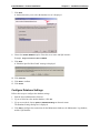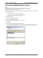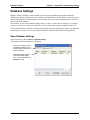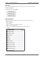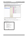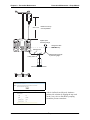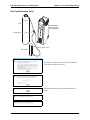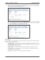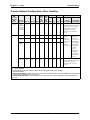
1
Alaris® System Maintenance v9.5.X
Software User Manual
Model 8975, v9.5.X
Guardrails® Suite MX
Compatible with v9.X Alaris® PC units
May 2010
Part Number: 11614346
®
Alaris System
Maintenance v9.5.X
Software User Manual
Part Number: 11614346
Alaris and Guardrails are
registered trademarks of
CareFusion Corporation or
one of its subsidiaries.
Masimo is a registered
trademark of Masimo
Corporation. Nellcor is a
registered trademark of
Nellcor Puritan Bennett,
Inc. Microstream is a
registered trademark of
Oridion Medical 1987 Ltd.
All other trademarks are
the property of their
respective owners.
CareFusion
San Diego, California
United States
888.876.4287
carefusion.com
© 2007-2010 CareFusion
Corporation or one of its
subsidiaries.
All rights reserved.
The information in this document is subject to change and does not represent a
commitment on the part of CareFusion to provide additional services or
enhancements. The screens illustrated in this document are for reference purposes
only and might be different than the screens displayed on your computer.
Documentation provided with this product might reference product not present in
your facility or not yet available for sale in your area.
If difficulties are encountered while using this software, refer to the applicable
Alaris® System Directions for Use (DFU) and/or service manual and related
service bulletin(s) before contacting CareFusion Technical Support. If necessary,
contact a CareFusion representative. Provide a description of the difficulty
experienced, any messages that were displayed at the time of the difficulty, and
the software version. Before you return the software to CareFusion, contact
CareFusion Customer Care to get a return authorization number. Put the software
in its original packaging (if available), write the return authorization number on
the package, and return it to the nearest facility.
Customer Advocacy - North America
(Clinical and technical feedback.)
Phone: 888.876.4287
E-mail: [email protected]
Customer Advocacy - International
(Clinical and technical feedback.)
E-mail: [email protected]
Technical Support - North America
(Maintenance and service information support; troubleshooting.)
Phone, United States: 888.876.4287
Phone, Canada: 800.387.8309
Technical Support - United Kingdom
(Maintenance and service information support; troubleshooting.)
Phone: 0800 389 6972
E-mail: [email protected]
Customer Care - North America
(Product return, service assistance, and order placement.)
Phone, United States: 888.876.4287
Phone, Canada: 800.387.8309
Customer Care - United Kingdom
(Product return, service assistance, and order placement.)
Phone: 0800 917 8776
E-mail: [email protected]
Technical Support and Customer Service - International
(Maintenance and service information support.
Product return, service assistance, and order placement)
www.carefusion.com/customer-support/customer-service
Authorized European Representative
CareFusion
The Crescent, Jays Close
Basingstoke, Hampshire RG22 4BS
United Kingdom
Contents
Chapter 1—Introduction
Defined Terms ............................................................................................................................................... 2
About the Software ........................................................................................................................................ 3
Feature Summary........................................................................................................................................... 4
Warnings........................................................................................................................................................ 5
Cautions ......................................................................................................................................................... 6
Chapter 2—Installation and Setup
System Requirements .................................................................................................................................... 8
Hardware Requirements ........................................................................................................................ 8
Software Requirements.......................................................................................................................... 8
Install Software—Standard Installation......................................................................................................... 9
Install Software—Custom Installation ........................................................................................................ 12
Install Centralized System Maintenance Software Database on a Dedicated Server ......................... 12
Install Client Tools on Biomedical Technician Workstation............................................................... 13
Configure Database Settings................................................................................................................ 15
Upgrade/Reinstall Software......................................................................................................................... 17
Uninstall Software ....................................................................................................................................... 18
System Maintenance Software CD ...................................................................................................... 18
Windows Operating System ................................................................................................................ 19
Uninstall AlarisSM9DB Database Instance................................................................................................. 20
Chapter 3—Overview
Start System Maintenance Software............................................................................................................ 22
Menu Bar ..................................................................................................................................................... 23
Chapter 4—PC Unit Connection
Hardware Connections................................................................................................................................. 26
Multiple PC Unit Connections..................................................................................................................... 27
Alaris® System Maintenance v9.5.X Software User Manual
i
Contents
Chapter 5—Application and Database Settings
Application Settings..................................................................................................................................... 30
Database Settings......................................................................................................................................... 31
Open Database Settings ....................................................................................................................... 31
Add a Database Definition................................................................................................................... 32
Delete a Database Definition ............................................................................................................... 32
Set Active Database Definition............................................................................................................ 32
Test Database Definition Connection .................................................................................................. 32
Migrate MSW Databases............................................................................................................................. 33
Chapter 6—Preventive Maintenance
Introduction.................................................................................................................................................. 36
General Steps ....................................................................................................................................... 37
Run/Abort Tasks .................................................................................................................................. 39
Run Tasks Concurrently............................................................................................................ 39
Abort Tasks ............................................................................................................................... 40
Coloring Scheme.................................................................................................................................. 40
Preventive Maintenance............................................................................................................................... 41
PC Unit ................................................................................................................................................ 41
Test Equipment ......................................................................................................................... 41
Pump Module....................................................................................................................................... 47
Test Equipment ......................................................................................................................... 47
Load Administration Set ........................................................................................................... 51
Rate Accuracy Test Setup ......................................................................................................... 52
Patient-Side Occlusion Pressure Test Setup.............................................................................. 55
Fluid-Side Occlusion Test Setup............................................................................................... 57
PCA Module ........................................................................................................................................ 59
Test Equipment ......................................................................................................................... 59
Syringe Module.................................................................................................................................... 67
Test Equipment ......................................................................................................................... 67
Pressure Test/Calibration Setup ................................................................................................ 75
SpO2 Module........................................................................................................................................ 77
Test Equipment ......................................................................................................................... 77
Disposable SpO2 Sensor Modification and Test Point.............................................................. 82
EtCO2 Module...................................................................................................................................... 84
Test Equipment ......................................................................................................................... 84
Leak-Down Test ........................................................................................................................ 87
Flow Test/Calibration Setup...................................................................................................... 89
Auto-ID Module and Handheld Scanner ............................................................................................. 91
Chapter 7—Data Sets and Alerts
Transfer a Data Set ...................................................................................................................................... 96
Download Alerts.......................................................................................................................................... 99
ii
Alaris® System Maintenance v9.5.X Software User Manual
Contents
Chapter 8—Flash Firmware
Flash Firmware .......................................................................................................................................... 106
PC Unit 8000 (PCU1.0) ..................................................................................................................... 106
PC Unit 8015 (PCU1.5) ..................................................................................................................... 111
Chapter 9—Configure Components
Configuration Packages ............................................................................................................................. 118
Components of a Configuration Package .......................................................................................... 119
Add a New Configuration Package ................................................................................................... 120
Delete a Configuration Package ........................................................................................................ 120
Export a Configuration Package ........................................................................................................ 120
Import a Configuration Package ........................................................................................................ 121
Export or Import Components of a Configuration Package .............................................................. 121
Copy a Configuration Package .......................................................................................................... 122
Copy a Component of a Configuration Package ............................................................................... 122
Specify Network Settings .................................................................................................................. 123
Create a Network Profile......................................................................................................... 123
Datalink Settings ..................................................................................................................... 123
Security Settings...................................................................................................................... 125
Network Settings ..................................................................................................................... 128
Server Settings......................................................................................................................... 129
Wireless Network Setting on PC Unit—Disable, Enable, View Status ............................................ 130
Enable Wireless Network........................................................................................................ 130
Disable Wireless Network....................................................................................................... 131
Specify Auto-ID Module Settings ..................................................................................................... 133
Formatting Rules ..................................................................................................................... 133
Specify Firmware Files...................................................................................................................... 137
Specify a Data Set File....................................................................................................................... 137
Chapter 10—Calibration
Introduction................................................................................................................................................ 140
Pump Module Calibration.......................................................................................................................... 141
Test Equipment .................................................................................................................................. 141
Patient-Side Occlusion Pressure Calibration Setup—Pump Module ................................................ 145
PCA Module Calibration ........................................................................................................................... 148
Test Equipment .................................................................................................................................. 148
Syringe Module Calibration ...................................................................................................................... 154
Test Equipment .................................................................................................................................. 154
EtCO2 Module Calibration ........................................................................................................................ 161
Test Equipment .................................................................................................................................. 161
Chapter 11—Tasks
Task Groups............................................................................................................................................... 166
Create a New Task Group.................................................................................................................. 166
Delete a Task Group .......................................................................................................................... 167
Rename a Task Group........................................................................................................................ 167
Alaris® System Maintenance v9.5.X Software User Manual
iii
Contents
Tasks List................................................................................................................................................... 168
Edit Tasks List ................................................................................................................................... 168
Change Tasks List Order ................................................................................................................... 168
Task Information ....................................................................................................................................... 170
PC Unit Tasks .................................................................................................................................... 170
Transfer Network Configuration—Error Handling ........................................................................... 174
Pump Module Tasks .......................................................................................................................... 175
Syringe Module and PCA Module Tasks .......................................................................................... 178
SpO2 Module Tasks ........................................................................................................................... 182
EtCO2 Module Tasks ......................................................................................................................... 183
Auto-ID Module and Handheld Scanner Tasks................................................................................. 184
Test Equipment.......................................................................................................................................... 185
Chapter 12—Reports and Logs
Reports....................................................................................................................................................... 188
Report Types...................................................................................................................................... 188
Run Reports ....................................................................................................................................... 188
Logs ........................................................................................................................................................... 190
Log Definitions .................................................................................................................................. 190
Example Log...................................................................................................................................... 193
Glossary ............................................................................................................................................... 199
iv
Alaris® System Maintenance v9.5.X Software User Manual
Chapter 1
Introduction
Alaris® System Maintenance v9.5.X Software User Manual
1
Chapter 1—Introduction
Defined Terms
Defined Terms
The following table identifies the defined terms used throughout this document for certain trademarked
products and product features.
Product/Feature
Defined Term
Alaris® Auto-ID module
Auto-ID Module
Alaris® EtCO2 module
EtCO2 Module
Alaris® PCA module
PCA Module
Alaris® PC unit
PC Unit
Alaris® Pump module
Pump Module
Alaris® SpO2 module
SpO2 Module
Alaris® Syringe module
Syringe Module
Alaris® System Maintenance
System Maintenance Software
Guardrails® alert
Alert
Guardrails® clinical advisories
Clinical Advisories
Guardrails® CQI report
CQI Report
Guardrails® data set
Data Set
Guardrails® Editor software
Editor Software
2
Alaris® System Maintenance v9.5.X Software User Manual
About the Software
Chapter 1—Introduction
About the Software
This software is provided under and subject to a license from CareFusion.
System Maintenance Software version 9.5.X allows you to perform routine maintenance on an
Alaris® System. The functionality of this software replaces maintenance software (MSW) and the Flash
tool for the Alaris® System. To use this software, you install it on a personal computer and then connect a
serial cable between the personal computer and a PC Unit.
The System Maintenance software kit includes:
• System Maintenance software CD-ROM
• Serial cable
• This Software User Manual (pdf on CD-ROM and printed version)
A USB serial adapter (not supplied) can be used to connect one or more PC Units to a personal computer
equipped with System Maintenance Software. The USB serial adapter must meet the following
specifications:
•
•
•
Plugs into a USB port on a personal computer.
Provides RS-232 male DB9 port(s) for direct connection to PC Units.
Draws its power from USB connection—a power adapter is not required.
Alaris® System Maintenance v9.5.X Software User Manual
3
Chapter 1—Introduction
Feature Summary
Feature Summary
System Maintenance software can be used to perform the following functions:
• Maintain the PC Unit.
• Upgrade firmware on the PC Unit and attached modules.
• Perform preventive maintenance/check-in.
• Set and check preventive maintenance reminder dates.
• Troubleshoot and repair instruments.
• Module Calibration, as applicable.
• Set up, test, and configure the Auto-ID Module.
• Download and view instrument logs.
• Download CQI data logs.
• Transfer Data Sets from the personal computer to the PC Unit.
• Configure wireless network settings.
• Test communications board interaction with a wireless network.
• Disable Wireless Network configuration option.
• Support wireless protocols for b, b/g, a/b/g, and d networks.
• Support wireless security for WEP, WPA, and WPA2.
Perform all pre-inspections before instrument use. A qualified technician or biomedical engineer must
perform inspections at least once a year or as required in accordance with CareFusion guidelines.
NOTE
•
•
4
Inspections are intended to comply with requirements specified by the
Joint Commission on Accreditation of Healthcare Organizations
(JCAHO).
You can purchase a service agreement from CareFusion for preventive
maintenance inspections.
Alaris® System Maintenance v9.5.X Software User Manual
Warnings
Chapter 1—Introduction
Warnings
Warnings provide information needed to safely and effectively use the Alaris® product.
A WARNING is an alert to a potential hazard which could result in serious personal injury and/or product
damage if proper procedures are not followed.
WARNING
•
At no time should the System Maintenance software be used while the
Alaris® System is connected to a patient.
•
System Maintenance software and procedures are intended to be
performed only by qualified personnel, or under direct supervision by
qualified personnel.
•
Prior to use, CareFusion recommends that you become familiar with
each instrument and accessory used with the System Maintenance
software. For specific instrument warnings, cautions, inspection
requirements, and other related instrument information, refer to the
applicable Alaris® System DFU and/or service manual.
•
The instrument case should only be opened by qualified service
personnel using proper grounding techniques. When the instrument
case is opened, electrical shock hazard exists which can result in
serious injury to persons and instrument component damage.
•
To ensure proper calibration, run the post tests for the Pump Module
and the accuracy tests for the Syringe Module after calibration. These
tests are displayed in the default Calibration test lists.
•
Ensure that the instrument is in operational status before returning it to
patient use.
•
Your PC Unit might not be compatible with every module. To determine
module compatibility, refer to the applicable Alaris® System DFU.
Alaris® System Maintenance v9.5.X Software User Manual
5
Chapter 1—Introduction
Cautions
Cautions
Cautions provide information needed to safely and effectively use the Alaris® product.
A CAUTION is an alert to a potential hazard which could result in minor personal injury and/or product
damage if proper procedures are not followed.
CAUTION
•
Loading the System Maintenance Software is considered a non-clinical
service activity. Interconnecting a medical device with a personal computer
might cause the safety or electromagnetic environment to change while the
connection exists. The threat of higher leakage currents or EMI disturbance
levels might be present. Remove the connection at both ends before patient
use.
•
By default, the System Maintenance Software is set to automatically clear
logs after they are downloaded. Once log entries have been cleared, they
cannot be downloaded again from the instrument. The log entries remain in
the database and can be displayed using the View Reports tab in the main
window.
•
Only one PC Unit should be connected to a group of attached modules at
any given time. Connection of multiple PC Units to each other will cause
damage to the IUI connectors.
•
Only one SpO2 Module can be connected to the PC Unit at any one time.
•
If a Pump Module fails the patient-side occlusion or rate accuracy verification
(RAV) tests, calibration is required. Failure to calibrate and retest the
instrument might result in improper instrument operation.
•
For tests that require water, use distilled water at room temperature between
41°F and 104°F (5°C to 40°C). If water is not within this temperature range,
the reading might be inaccurate.
•
If multiple instances of the System Maintenance Software are running
(typically on different personal computers), it is possible to assign different IP
addresses to the same PC Unit. To ensure this does not occur, assign each
PC Unit a single, unique IP address.
NOTE: If the System Maintenance Software instances are connected to the
same System Maintenance Software databases, this problem cannot occur.
•
Calibration verifications perform strenuous tests on the Syringe Module and
PCA Module. In some cases, these tests differ from the check-in/preventive
maintenance tests.
•
Following calibration, use calibration verifications (rather than check-in/
preventive maintenance verifications) to verify correct calibration.
•
Use of accessories or cables other than those specified might result in
degraded electromagnetic compatibility performance or safety of the Alaris®
System.
•
The flow rate out of the gas source and into the EtCO2 Module must be
greater than 0.5 liter/minute to ensure accurate readings. It is recommended
to place a flow meter between the gas source and the “T” in the line (breather
line).
6
Alaris® System Maintenance v9.5.X Software User Manual
Chapter 2
Installation and Setup
Alaris® System Maintenance v9.5.X Software User Manual
7
Chapter 2—Installation and Setup
System Requirements
System Requirements
To run the System Maintenance software, the personal computer must meet the following minimum
hardware and software requirements.
CAUTION
For optimum performance of the System Maintenance Software, ensure that the
personal computer is equipped with the required hardware and software, and do
not use the personal computer with unspecified accessories or cables. Use of
accessories or cables other than those specified might result in degraded
electromagnetic compatibility performance or safety of the Alaris® System.
Hardware Requirements
The personal computer on which you install the System Maintenance Software must meet the following
requirements:
•
•
•
•
•
•
•
•
processor, Pentium Class, 1 GHz or faster
RAM, 512 MB minimum
HDD (hard disk drive), 5 GB minimum of free space after the operating system is installed
CD-ROM drive
video card, SVGA
monitor, minimum resolution 1024 x 768; color depth set greater than 256 colors
port: configurable RS-232, 9-pin, serial communications; or USB
cable, serial communications (provided)
NOTES
•
•
•
•
•
If the personal computer has a serial port, use a serial-to-serial cable.
If the personal computer has a USB port, use a serial-to-USB cable or a
serial-to-serial cable with a USB converter. USB converter products are not
supported by CareFusion.
keyboard
mouse
printer and printer connection (optional)
Software Requirements
One of the following operating systems:
• Microsoft® Windows 2000 Professional with Service Pack 4
• Microsoft® Windows XP with Service Pack 2
• Microsoft® Windows 2003 Server with Service Pack 1
Other software:
•
8
Adobe Acrobat Reader v9.X
Alaris® System Maintenance v9.5.X Software User Manual
Install Software—Standard Installation
Chapter 2—Installation and Setup
Install Software—Standard Installation
Follow these steps to install the System Maintenance Software on a personal computer for the first time. If
you plan to migrate another version of the System Maintenance database, install the System Maintenance
Software and migrate the data using the Migrate MSW file feature (Options > Migrate MSW Data).
Read all prompts carefully. During installation it is recommended that no other applications are running
and that virus checking is disabled.
1. Insert the System Maintenance Software CD into the CD-ROM drive of the personal computer. If the
installation program automatically starts, go to the next step. If the installation program does not
automatically start, choose Start > Run, then type d:\Setup.exe (where d: is CD drive).
Alternatively, browse to the Setup.exe program on the System Maintenance Software CD, click Open,
and then click OK.
2. When you are asked if you want to install SQL Server 2005 Express, click Yes.
3. If you are prompted to install prerequisite components, click Install. The components include
Microsoft® .NET Framework 2.0, MSXML 6.0, Microsoft Report Viewer 2005, ASM Database (SQL
Server Express 2005), and Adobe Reader 9.0.
Alaris® System Maintenance v9.5.X Software User Manual
9
Chapter 2—Installation and Setup
Install Software—Standard Installation
4. After installing prerequisites, or if prerequisites are already installed, the installation Setup Wizard
Welcome window is displayed. Click Next.
5. Select the features that you want to install:
• Full Install—installs System Maintenance databases and client tools.
• Database—installs only System Maintenance databases.
• Client Tools—installs only System Maintenance client tools.
To install only the database, click Client Tools and click the red X. To install only the client tools, click
Database and click the red X.
10
Alaris® System Maintenance v9.5.X Software User Manual
Install Software—Standard Installation
Chapter 2—Installation and Setup
6. Click Browse to choose a location other than the default installation directory. The default directory is
C:\Program Files\Cardinal Health\Alaris Products\Alaris System Maintenance\.
If an existing database is found, the following window is displayed. You can use the existing database
(default) or overwrite the existing database (previous data will be lost). If a previous System
Maintenance database was not found, this window will not be displayed.
7. Click Next to begin installation of the components of the System Maintenance Software.
8. Click Next to confirm installation.
When the installation is finished, an "Installation Complete" message is displayed. It is recommended
that you restart your computer if prompted to do so.
Alaris® System Maintenance v9.5.X Software User Manual
11
Chapter 2—Installation and Setup
Install Software—Custom Installation
Install Software—Custom Installation
Install Centralized System Maintenance Software Database on a
Dedicated Server
1. Insert the System Maintenance Software CD into the CD-ROM drive of the personal computer. If the
installation program starts automatically, go to the next step. If the installation program does not start
automatically, choose Start > Run, then type d:\Setup.exe (where d: is CD drive). Alternatively,
browse to the Setup.exe program on the System Maintenance Software CD, click Open, and then click
OK.
2. When you are asked if you want to install SQL Server 2005 Express, click Yes.
3. If you are prompted to install prerequisite components, click Install. The components include
Microsoft .NET Framework 2.0, MSXML 6.0, Microsoft Report Viewer 2005, ASM Database (SQL
Server Express 2005), and Adobe Reader 9.X.
4. Wait until the installation is completed. When the Alaris® System Maintenance welcome wizard is
displayed, click Next.
12
Alaris® System Maintenance v9.5.X Software User Manual
Install Software—Custom Installation
Chapter 2—Installation and Setup
5. On the Custom Setup window, ensure that Client Tools is not selected (unless you want to also install
the client tools on the same computer as the System Maintenance database).
6. Click Next.
7. Click Finish.
Install Client Tools on Biomedical Technician Workstation
Follow these steps to install the client tools on the Biomedical Technician Workstation.
1. Insert the System Maintenance Software CD into the CD-ROM drive of the personal computer. If the
installation program starts automatically, go to the next step. If the installation program does not start
automatically, choose Start > Run, then type d:\Setup.exe (where d: is CD drive). Alternatively,
browse to the Setup.exe program on the System Maintenance Software CD, click Open, and then click
OK.
2. When you are asked if you want to install SQL Server 2005 Express, click No.
Alaris® System Maintenance v9.5.X Software User Manual
13
Chapter 2—Installation and Setup
Install Software—Custom Installation
3. If you are prompted to install prerequisite components, click Install. The components include
Microsoft .NET Framework 2.0, MSXML 6.0, Microsoft Report Viewer 2005, and Adobe Reader 9.0.
4. Wait until the installation is completed. When the Alaris® System Maintenance welcome wizard is
displayed, click Next.
5. On the Custom Setup window, ensure that Database is not selected.
6. If the Database option is selected and you chose not to install SQL Server 2005 Express, a message is
displayed. Click Ok to close the message window.
14
Alaris® System Maintenance v9.5.X Software User Manual
Install Software—Custom Installation
Chapter 2—Installation and Setup
7. Click Next.
A window that asks you to select the database server is displayed.
8. Choose the Remote Database option. Enter the server name and SQL instance.
Example: HospitalServer\AlarisSM9DB
9. Click Next.
A "Machine Specified Not Found" message is displayed.
10. Click Continue.
11. Click Next to confirm.
12. Click Finish.
Configure Database Settings
Follow these steps to configure the database settings.
1. Start the System Maintenance Software.
2. If you are asked to select another database, click Yes.
3. If you are not asked, choose Options > Database Settings on the main menu.
The Database Settings dialog box is displayed.
4. Click Add to configure the connections for the Maintenance database, the Maintenance Log database,
and the CQI Database.
Alaris® System Maintenance v9.5.X Software User Manual
15
Chapter 2—Installation and Setup
Install Software—Custom Installation
Hospital Server
Database
Field Values
Maintenance database
SQL Server field = <HospitalServer>\AlarisSM9DB
Database field = Maintenance
Maintenance Log database
SQL Server field = <HospitalServer>\AlarisSM9DB
Database field = MaintenanceLog
CQI Database
SQL Server field = <HospitalServer>\CQI9DB
Database field = CQI
Standalone Computer
Database
Field Values
Maintenance database
SQL Server field = (local)\AlarisSM9Db
Database field = Maintenance
Maintenance Log database
SQL Server field = (local)\AlarisSM9Db
Database field = MaintenanceLog
CQI Database
SQL Server field = (local)\CQI9DB
Database field = CQI
NOTE
If a database does not exist on your local database server, the "(local)" SQL
Service field is replaced with the SQL Server name where the database is
installed.
Alaris® Server (wireless)
Database
Field Values
CQI Database
SQL Server field = <AlarisAPPSServer>
Database field = CQI
5. Click Test Connection to verify the connection to the database.
16
Alaris® System Maintenance v9.5.X Software User Manual
Upgrade/Reinstall Software
Chapter 2—Installation and Setup
Upgrade/Reinstall Software
Before you can upgrade or reinstall the System Maintenance Software, you must uninstall the existing
software.
NOTE
Uninstalling the AlarisSM9DB database is NOT required to upgrade/reinstall the
software (Uninstall AlarisSM9DB Database Instance on page 20).
1. Uninstall the existing software (see Uninstall Software on page 18).
2. Install/reinstall the software (see Install Software—Standard Installation on page 9 or Install
Software—Custom Installation on page 12).
Alaris® System Maintenance v9.5.X Software User Manual
17
Chapter 2—Installation and Setup
Uninstall Software
Uninstall Software
There are two ways to uninstall the System Maintenance Software. The method that you use depends on
the version of software that you are uninstalling.
•
•
System Maintenance Software CD: Use this method if the software being removed and the
software that will be installed are the same software version.
Windows Operating System: Use this method if the software being removed will be replaced with
a different version of the software.
System Maintenance Software CD
1. Insert the System Maintenance Software CD into the CD-ROM drive of the personal computer. The
installation program starts automatically. If the installation program does not start, choose Start > Run,
then type d:\Setup.exe (where d: is CD drive). Alternatively, browse to the Setup.exe program on
the System Maintenance Software CD, click Open, and then click OK.
2. Enter information about installation as prompted, including destination.
3. When the message that a previous installation has been detected is displayed, click Remove to
completely remove the existing System Maintenance Software and its components. Existing data is
preserved.
4. Clicking Remove displays the following confirmation window. Click Remove again to initiate the
uninstall process.
5. When a message that indicates the software has been successfully uninstalled is displayed, click Finish.
18
Alaris® System Maintenance v9.5.X Software User Manual
Uninstall Software
Chapter 2—Installation and Setup
Windows Operating System
1. Choose Start > Settings > Control Panel.
2. Double-click Add or Remove Programs.
3. Click Alaris® System Maintenance.
4. Click Remove.
5. Follow the prompts to complete the uninstallation procedure.
Alaris® System Maintenance v9.5.X Software User Manual
19
Chapter 2—Installation and Setup
Uninstall AlarisSM9DB Database Instance
Uninstall AlarisSM9DB Database Instance
NOTE
All data will be lost when uninstalling the AlarisSM9DB database. Ensure that the
database is backed up for future reference.
Use this procedure to uninstall the AlarisSM9DB database instance of Microsoft SQL Server 2005 Express
and the following software:
• Microsoft SQL Server Native Client (if applicable)
• Microsoft SQL Server Setup Support Files (if applicable)
• Microsoft SQL Server VSS Writer (if applicable)
To uninstall the software:
1. Choose Start > Settings > Control Panel.
2. Double-click Add or Remove Programs.
3. Select the software (listed above) that you want to uninstall.
4. Click Remove.
5. Follow the prompts to complete the removal procedure.
If you are uninstalling Microsoft SQL Server 2005, when the following dialog box is displayed, select
the instance named "AlarisSM9DB" and then click Next to continue with the removal procedure.
20
Alaris® System Maintenance v9.5.X Software User Manual
Chapter 3
Overview
Alaris® System Maintenance v9.5.X Software User Manual
21
Chapter 3—Overview
Start System Maintenance Software
Start System Maintenance Software
1. On the personal computer desktop, double-click the Alaris® System Maintenance icon (or choose the
program from the Start menu).
A series of status boxes is displayed as the System Maintenance Software scans for communication
ports and establishes communication with connected devices.
When the startup routine is complete, the main window of the System Maintenance Software is
displayed.
2. To check the version of System Maintenance Software, choose Help > About Alaris® System
Maintenance.
Menu Bar
Tabs in the main window let you
perform maintenance tasks, view
reports from the maintenance
database, configure task lists,
and configure device parameters
The Connected Devices pane
contains a list of the devices that
are connected to each of the
communication ports on the
personal computer.
This pane contains task
instructions, input fields, and
report data.
22
Alaris® System Maintenance v9.5.X Software User Manual
Chapter 3—Overview
Menu Bar
Menu Bar
•
•
File
(F5)—Refresh all ports.
°
Refresh
°
Refresh Selected Port (Ctrl + F5)—Refresh the port that is selected in the Connected Devices pane.
°
Exit (Alt
+ F4)—Exit the software.
Options
°
Application Settings—See
°
Database Settings—See
°
°
Application Settings on page 30.
Database Settings on page 31.
Export—Export the CQI Database as well as information for all devices that have been connected
to the PC Unit.
Import—Import
the CQI Database as well as information for all devices that have been connected
to the PC Unit.
°
•
Migrate MSW Data—Import
a previous maintenance software v8 database.
Help
About Alaris® System Maintenance—View
version and copyright information.
Alaris® System Maintenance v9.5.X Software User Manual
23
Chapter 3—Overview
Menu Bar
This page intentionally left blank.
24
Alaris® System Maintenance v9.5.X Software User Manual
Chapter 4
PC Unit Connection
Alaris® System Maintenance v9.5.X Software User Manual
25
Chapter 4—PC Unit Connection
Hardware Connections
Hardware Connections
This section describes how to connect a PC Unit to the personal computer.
WARNING
At no time should the System Maintenance Software be used while the
Alaris® System is connected to a patient.
1. If a rubber plug is covering the communications port, remove it.
Communications
port (remove rubber
plug if present)
PC Unit (back)
2. Connect the small end of the serial cable to the communications port on the back of the PC Unit.
Serial cable
(both ends shown)
3. Connect the large end of the serial cable to a serial port on the personal computer.
4. If the PC Unit is not on, press the System On key.
5. If the System Maintenance Software is not running, start it.
6. Press F5 to refresh the ports.
Information about the PC Unit and attached modules is displayed in the Connected Devices pane.
26
Alaris® System Maintenance v9.5.X Software User Manual
Multiple PC Unit Connections
Chapter 4—PC Unit Connection
Multiple PC Unit Connections
You can connect as many PC Units as there are available serial COM ports on the personal computer. To
view all available COM ports:
1. On the main menu, click Options > Application Settings.
2. In the drop-down menu labeled Show only connected ports, click False.
3. Close the Application Settings window.
After a File/Refresh, a list of all available COM ports is displayed in the Connected Devices pane,
whether or not they have a PC Unit attached.
4. Connect the PC Units to the available ports.
5. Press F5 to refresh the view for all ports, or press Ctrl+F5 to refresh only the port that is selected in the
Available Devices pane. These options are also available in the File menu.
When a port refresh is selected, a list of connected devices is displayed in the Connected Devices pane.
If problems occur when using the refresh feature while connected to a 4-port replicator, consider
restarting the System Maintenance Software to restore the connection.
Alaris® System Maintenance v9.5.X Software User Manual
27
Chapter 4—PC Unit Connection
Multiple PC Unit Connections
This page intentionally left blank.
28
Alaris® System Maintenance v9.5.X Software User Manual
Chapter 5
Application and Database Settings
Alaris® System Maintenance v9.5.X Software User Manual
29
Chapter 5—Application and Database Settings
Application Settings
Application Settings
Use the Application Settings dialog box to configure the available application options for the System
Maintenance Software. To open the Application Settings dialog box:
1. On the main menu, choose Options > Application Settings.
The Application Settings dialog box is displayed.
2. To change an application setting, click the column to the right of that setting and make the appropriate
change.
3. Close the Application Settings dialog box to save your changes.
Setting
Description
Flash
• Allow serial number update
If true, the device serial number can be set through flash
tasks.
• Default SpO2 Module for Flash
When flashing the firmware on an SpO2 Module, either
Nellcor® or Masimo® can be selected as the default
firmware.
General
• Beep for user input
If true, causes application to beep when a running task
requires attention.
• Beep on finished task
If true, causes application to beep when a task finishes.
• Enable task list edit button
If true, task list edit button is enabled, allowing Task
List to be edited.
• Show only connected ports
If true, only communication ports that have devices
connected to them are displayed in the Connected
Devices pane. If false, all available ports are displayed.
Log Downloading
If either clear downloaded logs setting is set to True,
the software automatically clears the log during
download. If you are performing an instrument
investigation, CareFusion recommends that the logs not
be cleared until the investigation is completed.
• Clear downloaded CQI logs
If true, CQI logs are cleared from connected devices
after download.
• Clear downloaded logs
If true, all battery, error, and event logs (other than CQI
logs) are cleared from connected devices after
download. This setting does not affect whether CQI logs
are cleared after downloading. The clearing of CQI logs
after downloading is managed separately from all other
settings used to clear logs.
Package Components
Ignore incomplete packages
30
If true, any empty packages are ignored and do not
produce an error.
Alaris® System Maintenance v9.5.X Software User Manual
Database Settings
Chapter 5—Application and Database Settings
Database Settings
Multiple database definitions can be defined for the three System Maintenance Software databases
(Maintenance database, Maintenance Log database, and CQI database). Each definition contains the server
name and authentication for the databases. Once defined, the user can select which database to use from
this list of defined databases.
Once defined, do not change database settings unless you have a valid reason for doing so. For example,
you may need to select a site-specific database in an environment that supports multiple hospital sites.
The System Maintenance Software automatically connects to the default database locations, but additional
customizing may need to occur if your database definition is different from these default parameters.
Open Database Settings
On the main menu, choose Options > Database Settings.
The Database Selection dialog box is displayed.
Select a tab to display the list
of database definitions for the
selected System Maintenance
Software database.
Database definitions relating
to the selected tab display
here. The active definition has
Default set to Yes.
Alaris® System Maintenance v9.5.X Software User Manual
31
Chapter 5—Application and Database Settings
Database Settings
Add a Database Definition
1. Click the tab of the desired System Maintenance Software database.
2. Click Add.
The Database Settings dialog box is displayed.
3. Select an SQL Server.
4. Select a Database name on this SQL Server.
5. Click Test Connection to test the connection to the server.
6. Click OK to acknowledge the test connection.
7. Click OK to save the definition.
Delete a Database Definition
1. Click the tab of the desired System Maintenance Software database.
2. Click the database definition that you want to delete.
3. Click Delete.
A confirmation dialog box is displayed.
4. Click OK to delete the database definition.
Set Active Database Definition
1. Click the tab of the desired System Maintenance Software database.
2. Click the database definition to make it active.
3. Click Set Default.
The System Maintenance Software now uses the selected definition as the active database and begins
logging data to it as data is collected.
Test Database Definition Connection
1. Click the tab of the desired System Maintenance Software database.
2. Click the database definition to select it.
3. Click Test Connection.
If the connection fails, check the database definition for errors.
32
Alaris® System Maintenance v9.5.X Software User Manual
Migrate MSW Databases
Chapter 5—Application and Database Settings
Migrate MSW Databases
There are two separate MSW application databases, MSW and MSW Log. Use the following procedure to
migrate the MSW databases to the System Maintenance Software database.
1. On the main menu, click Options > Migrate MSW Data.
The Database Selection screen is displayed:
2. If the desired MSW or MSW Log databases are not listed, continue with the following steps;
otherwise, proceed to step 3.
NOTE
The desired MSW databases (MSW and MSW Log) must be configured as
default DB.
Alaris® System Maintenance v9.5.X Software User Manual
33
Chapter 5—Application and Database Settings
Migrate MSW Databases
a. Click the tab for the applicable database and then click Add. The Database Settings screen is
displayed.
b. Select the desired server from the SQL Server drop-down list.
c. From the Database name drop-down list, select MTR for the MSW database or IMSLog for the
MSW Log database.
NOTE
If the required database is not in the Database name drop-down list, the selected
SQL Server is not correct.
d. Click Test Connection to have the software verify that the MSW database configuration is correct.
3. Click on desired database.
4. Click Migrate—located at the bottom of the Database Selection screen—to start data migration.
The data migration progress screen is displayed. When the migration process is complete, the
application displays the status of the migration.
34
Alaris® System Maintenance v9.5.X Software User Manual
Chapter 6
Preventive Maintenance
Alaris® System Maintenance v9.5.X Software User Manual
35
Chapter 6—Preventive Maintenance
Introduction—
Introduction
WARNING
At no time should the System Maintenance Software be used while the
Alaris® System is connected to a patient.
Preventive maintenance can be performed on connected modules by selecting from a list of automated
tasks. Tasks can be individual tasks that exist in the list of master tasks or task groups that contain a
collection of the individual tasks required to maintain devices.
Standard task groups include:
Check-in
Tasks required to check any module newly received into
the facility. Run check-in on a newly received module to
confirm that it was not damaged during transport and is
ready to be put into use. System Maintenance Software
guides you through check-in.
The final task in the Check-in task group allows you to
set a Preventive Maintenance (PM) Reminder Date to
remind the user when preventive maintenance is due.
Preventive Maintenance
Tasks required to perform regular maintenance on a
module.
Run preventive maintenance tests a minimum of once a
year to confirm that modules are performing correctly.
System Maintenance Software guides you through
preventive maintenance tests.
Final task in Preventive Maintenance task group allows
you to set the next PM Reminder Date to remind the
user when preventive maintenance is due.
Calibration
Tasks required to test whether calibration is required and
to calibrate connected modules.
The calibration task group applies to EtCO2 Module,
Syringe Module, PCA Module, and Pump Module.
36
Alaris® System Maintenance v9.5.X Software User Manual
Introduction—General Steps
Chapter 6—Preventive Maintenance
General Steps
The main window is shown below. When you click a node such as My Computer in the Connected Devices
pane, information on how to proceed is displayed in the right pane.
1. Click the Perform Maintenance tab.
2. Select the module (device).
The Tasks list is displayed.
NOTE
•
The tasks in the Tasks list vary depending on which module you have
selected and how the tasks are configured.
•
You can edit the Tasks list, if desired (see Tasks List on page 168).
Alaris® System Maintenance v9.5.X Software User Manual
37
Chapter 6—Preventive Maintenance
Introduction—General Steps
3. Click Preventive Maintenance in the Tasks list (Pump Module screen used as an example in following
illustration).
NOTE
As a shortcut, you can double-click the task to select it and start it immediately.
4. If Preventive Maintenance was not automatically started, click Start Selected Tasks.
5. Follow all on-screen instructions carefully to ensure the successful completion of the task.
If a task fails, the System Maintenance Software asks you if you want to rerun the failed task.
NOTE
At the end of some tests you are asked to indicate if the test passed or failed.
Other tests automatically indicate a pass or fail result.
38
°
To rerun the task, click Yes.
°
To continue to the next task in a task group, click No.
°
To correct a failure, abort the selected task and refer to the applicable Technical Service Manual.
Alaris® System Maintenance v9.5.X Software User Manual
Introduction—Run/Abort Tasks
Chapter 6—Preventive Maintenance
6. When finished, click Reset Selected Tasks to return a module to the READY state (Pump Module screen
used as an example in following illustration).
Run/Abort Tasks
Run Tasks Concurrently
You can run selected tasks concurrently on different connected modules. One PC Unit and a serial port is
needed for each module being tested. Once you have started selected tasks on one connected device, select
other devices in the Connected Devices pane and start tasks for those devices, if desired.
The status bar displays devices that are currently running tasks. If attention is required by a device to
continue a task, the device progress bar and the Details Pane Task button for that task will be orange.
Select the device in the Connected Devices pane to display its task instructions and follow the displayed
task instructions.
The System Maintenance Software sounds an alarm when a device needs attention or when a task is
finished, if these options are set. For information on setting these options, see Application Settings on
page 30.
Alaris® System Maintenance v9.5.X Software User Manual
39
Chapter 6—Preventive Maintenance
Introduction—Coloring Scheme
Abort Tasks
You can abort (cancel) any running task that is currently selected in the Connected Devices pane.
Click Abort Selected Tasks.
The status of the task is reset to CANCEL.
Coloring Scheme
The preventive maintenance test results are identified using the following color scheme:
Blue—test passed
Brown—test aborted
Red—test failed
Orange—test is running, but waiting for user input
Purple—test has not yet been run
Green—test is automatically running (not requiring user input at this time)
Example:
40
Alaris® System Maintenance v9.5.X Software User Manual
Chapter 6—Preventive Maintenance
Preventive Maintenance—PC Unit
Preventive Maintenance
To perform preventive maintenance, see the procedure in this section that applies to the module being
tested:
PC Unit on page 41
Pump Module on page 47
PCA Module on page 59
Syringe Module on page 67
SpO2 Module on page 77
EtCO2 Module on page 84
Auto-ID Module and Handheld Scanner on page 91
PC Unit
Test Equipment
Test Equipment
Manufacturer
analyzer, electrical safety Fluke BioMedical
Model Number
Application
232D or equivalent
ground tests
1. In the Connected Devices pane, click the PC Unit to be tested.
2. Click Preventive Maintenance in the Tasks list (double-click to begin testing immediately).
3. Follow the instructions displayed on the screen for each test.
NOTE
See PC Unit Tasks on page 170 for an explanation of each task.
Alaris® System Maintenance v9.5.X Software User Manual
41
Chapter 6—Preventive Maintenance
Preventive Maintenance—PC Unit
4. Instrument Inspection:
If the test failed, click Abort Selected Tasks—in
the Tasks list—to discontinue testing. Correct the
failure(s) before continuing with the tests.
42
Alaris® System Maintenance v9.5.X Software User Manual
Preventive Maintenance—PC Unit
Chapter 6—Preventive Maintenance
5. Simultaneous Display:
If you want the test to run continuously, click the Run test in continuous mode checkbox.
•
•
•
Look for missing pixels (display elements) as each screen is displayed.
The Model 8000 displays dark gray and light gray screens. The Model 8015 displays dark gray,
light gray, white, red, green, and blue screens.
If the screen brightness or contrast appears weak, check the contrast setting (refer to applicable
Alaris® System DFU).
6. IUI Connectors:
'Sandwiching'—the PC Unit has one module
attached to each side.
Alaris® System Maintenance v9.5.X Software User Manual
43
Chapter 6—Preventive Maintenance
Preventive Maintenance—PC Unit
7. Alarm:
If the audio is weak, check the audio volume
setting (refer to applicable Alaris® System DFU).
8. Keypad:
NOTE
Press and hold the Tamper Switch (on back of PC Unit) for at least two seconds,
until there is a response to the test.
Press each key one time.
•
•
Green text—the key was pressed one time and passed the test.
Red text—the key was pressed two times, or it was pressed one time and failed the test. If the text
is red because you pressed the key more than one time, you can indicate that the test has passed.
9. Nurse Call:
This test is performed only if a Nurse Call is installed and applies only to the Model 8000.
44
Alaris® System Maintenance v9.5.X Software User Manual
Chapter 6—Preventive Maintenance
Preventive Maintenance—PC Unit
10. Ground Leakage:
The ground leakage test is not performed by the System Maintenance Software. The leakage current
table provided below reflects IEC/UL 60601-1 requirements. The limits identified in the table are to be
used in place of the 100 µA leakage current limit specified by the software.
Use a Fluke Biomedical Model 232D or
equivalent electrical safety analyzer to measure
the ground leakage current. Refer to the test
equipment’s operation manual for the proper
measurement technique.
The line voltage must be the same as the voltage
that powers the tester and then passes to the
instrument being tested.
Use the following table—in place of the
requirements identified by the software—to
determine the leakage current requirements for
normal and reversed line polarity. The limits are
100 µA below the IEC/UL 60601-1 standard
limits to account for test variances.
AC Supply
Leakage Current—
Maximum
Japan
100 VAC
400 µA
North America
120 VAC
200 µA
Rest of World
230 VAC
400 µA
Australia
New Zealand
240 VAC
400 µA
11. Ground Resistance:
The ground resistance test is not performed by the System Maintenance Software. Use the following
instructions and illustration to perform this test—in place of the instructions displayed by the software.
Use a Fluke Biomedical Model 232D, an Ohm
Meter, or an equivalent electrical safety analyzer
to measure the ground resistance between the
ground pin on power cord plug or power cord
receptacle, and the rear panel of the PC Unit. Refer
to the test equipment’s operation manual for the
proper measurement technique.
The maximum allowable resistance is 1 Ohm.
Alaris® System Maintenance v9.5.X Software User Manual
45
Chapter 6—Preventive Maintenance
Preventive Maintenance—PC Unit
The following illustration is a partial view of the rear of the PC Unit. In the illustrated example of
a ground contact, a Kelvin Clip is clipped to a speaker slot on the rear panel. The only acceptable
ground contact area is the rear panel—gold anodized color metal (shaded area in illustration).
NOTE
The following illustration reflects the use of the Kelvin Clip that is provided with
the Fluke tester. If another tester or Ohm Meter is used, the test measures the
resistance between the rear panel (shaded area in illustration) and the ground pin
on the power cord plug or power cord receptacle.
12. Set PM Reminder:
•
•
46
If Enable Maintenance Reminder is selected, a Data Set is loaded and the configuration option for
the Data Set is set to Disable. The Data Set setting overrides the System Maintenance Software
selection.
The next maintenance reminder date defaults to 12 months. The reminder can be set to an earlier
date but it cannot be set to a date past the 12-month default.
Alaris® System Maintenance v9.5.X Software User Manual
Chapter 6—Preventive Maintenance
Preventive Maintenance—Pump Module
Pump Module
Test Equipment
Test Equipment
Manufacturer
gauge, pressure, digital
(peak hold)
Either of the following:
pressure test
• PTE-1 (accuracy from 0.1 to
• Heise
0.025% span)
(www.heise.com)
• 2089, 2086, or 2084 (accuracy
• Ashcroft
from ±0.05%, 0.10%, or
(www.ashcroft.com)
0.25% of span)
• or an equivalent gauge with:
(a) unit of measure in mmHg
(b) accuracy of ±1%
(c) range of 0-1500 mmHg
hemostat
N/A
N/A
fluid-side occlusion test
IV pole, standard
CareFusion
903-0336 or equivalent
rate, pressure, and occlusion tests
• CareFusion
• 2210-0500
• CareFusion
• CareFusion
• 8100-RCS
• 8100-PCS
IV solution container
(bag preferred)
N/A
N/A
luer lock, female,
1/8"-27 NPT
Cole-Parmer
K-45503-78 or equivalent
(www.coleparmer.com)
pressure test
reducer, female,
1/4" NPT (F) x
1/8" NPT (F)
Cole-Parmer
K-06349-91 or equivalent
(www.coleparmer.com)
pressure test
scale, digital
Acculab
(www.acculab.com)
VIC-212 (VICON Series) or
equivalent with accuracy of
±0.01g
rate and pressure tests
tubing, silicone
CareFusion
303109 or equivalent
pressure test
T-fitting
CareFusion
303815 or equivalent
pressure test
valve, 3-way
CareFusion
97555 or equivalent
pressure test
IV sets
• IV set, standard,
without check valve
• IV set, calibration
• IV set, calibration
Model/Part Number
Application
rate and pressure tests
Alaris® System Maintenance v9.5.X Software User Manual
rate and pressure tests
47
Chapter 6—Preventive Maintenance
Preventive Maintenance—Pump Module
1. In the Connected Devices pane, click the Pump Module to be tested.
2. Click Preventive Maintenance in the Tasks list (double-click to begin testing immediately).
3. Follow the instructions displayed on the screen for each test.
NOTE
See Pump Module Tasks on page 175 for an explanation of each task.
4. Instrument Inspection:
48
Alaris® System Maintenance v9.5.X Software User Manual
Preventive Maintenance—Pump Module
Chapter 6—Preventive Maintenance
If the test failed, click Abort Selected Tasks to discontinue testing. Correct the failure(s) before
continuing with the tests.
5. Simultaneous Display:
If you want the test to run continuously, select Run test in continuous mode.
•
•
•
Channel ID display—all segments must light.
Scrolling display and Rate display—must flash dashes and zeros.
Lighthouse LED’s—all LEDs must light.
Alaris® System Maintenance v9.5.X Software User Manual
49
Chapter 6—Preventive Maintenance
Preventive Maintenance—Pump Module
6. IUI Connectors:
’Sandwiching’—the module being tested is connected
between the PC Unit and another module.
7. Alarms:
If the audio is weak, check the audio volume
setting (refer to applicable Alaris® System DFU).
If the audio is weak, check the audio volume setting (refer to applicable Alaris® System DFU).
8. Keypad:
Press each key one time.
•
•
50
Green text—the key was pressed one time and passed the test.
Red text—the key was pressed two times, or it was pressed one time and failed the test. If the text
is red because you pressed the key more than one time, you can indicate that the test has passed.
Alaris® System Maintenance v9.5.X Software User Manual
Chapter 6—Preventive Maintenance
Preventive Maintenance—Pump Module
9. Door Ajar-Flo-Stop Sensors:
54
Load Administration Set
Install an administration set as shown for any Pump Module test. Unless otherwise specified, in order
to run a Pump Module test, the set must be loaded and the Pump Module door must be closed.
Ensure that the pumping
segment is vertical across the
center of the pressure sensors.
Ensure that the tubing is fully
inserted in the Air-in-Line
Sensor.
Alaris® System Maintenance v9.5.X Software User Manual
51
Chapter 6—Preventive Maintenance
Preventive Maintenance—Pump Module
10. Air-in-Line Sensor:
11. Rate Accuracy:
CAUTION
If the Pump Module fails the rate accuracy test, calibration is required. Failure to
perform calibration tests might result in improper operation.
Set up the Pump Module for the Rate Accuracy test.
Rate Accuracy Test Setup
CAUTION
•
If the Pump Module fails the rate accuracy verification test, calibration is
required. Failure to perform calibration tests might result in improper
operation.
•
To ensure accurate rate calibration, use only rate calibration sets. Rate
accuracy calibration sets are valid for 60 calibrations and must be replaced
after 60 uses.
•
Use distilled water at room temperature of 41°F to 104°F (5°C to 40°C). If the
water temperature is not within this range, the readings might be inaccurate.
Use this setup to perform the following tests:
• Rate accuracy verification—Tasks: Rate Accuracy, Check-in, and Preventive Maintenance.
• Rate accuracy calibration pre-test—Task: Rate Accuracy Pre-Test.
• Rate accuracy calibration—Task: Rate Calibration.
• Rate accuracy calibration post-test—Task: Rate Accuracy Post-Test.
All tests use a standard set except for the rate accuracy verification (Task: Preventive Maintenance)
and the rate accuracy calibration. These tests require the use of the Model 8100-RCS rate calibration
set.
Verify that the scale is calibrated according to the manufacturer's instructions. Prime the fluid lines and
keep them free of air bubbles while running the test.
If the rate accuracy calibration pre-test fails, perform the rate accuracy calibration. Following
calibration, run the rate accuracy calibration post-test using a different rate calibration set to test the
module with the newly calibrated parameters.
—See the test setup illustration on the following page.—
52
Alaris® System Maintenance v9.5.X Software User Manual
Chapter 6—Preventive Maintenance
Preventive Maintenance—Pump Module
Distance is from top
of Pump Module
20±1 inch
Top of cup must be
level with CHANNEL
SELECT key.
CHANNEL
SELECT
CHANNEL
SELECT
PUMP
PUMP
PAUSE
PAUSE
SYSTEM
CHANNEL
OFF
CHANNEL
OFF
RESTART
RESTART
1
2
3
4
7
5
6
8
0
9
CLEAR
.
ENTER
CANCEL
Ensure that the set is properly loaded (see Load
Administration Set on page 51). Ensure that
there are no air bubbles in the set when priming
is completed.
The Expected Volume is identified on the label
attached to the characterized set.
Error message—first occurrence
If an error message appears after clicking Next, perform the following steps.
NOTE
If this is not the first occurrence of an error message and the following procedure
has already been performed, perform Error message—repeat occurrence.
Alaris® System Maintenance v9.5.X Software User Manual
53
Chapter 6—Preventive Maintenance
Preventive Maintenance—Pump Module
a. Click OK and visually confirm that:
• The set is properly loaded in the Pump Module.
• There are no air bubbles in the set.
b. Click Yes on the message that appears.
c. Detach and reattach the Pump Module with set installed.
d. Repeat the rate accuracy test after the Pump Module reinitializes.
Error message—repeat occurrence
If an error message appears after clicking Next, manually connect to the Maintenance Mode and
retest, as follows:
a. Abort the selected task.
a. Exit the System Maintenance Software.
b. Turn off the PC Unit.
c. Ensure that the serial cable is connected between the communications port on the PC Unit and
the computer.
d. Press and hold the Tamper Switch and the System On key on the PC Unit until the PC Unit
beeps once and displays the Maintenance Mode screen.
e. Press the Proceed soft key and then press the External Communications soft key.
f.
Start the System Maintenance Software.
g. Perform Preventive Maintenance.
When performing the Rate Accuracy test, follow the instructions to ensure that the set is
properly loaded and that there are no air bubbles in the set when priming is completed.
Ensure that the distilled water is dripping into the
cup and that the tubing is not resting on the scale.
54
Alaris® System Maintenance v9.5.X Software User Manual
Preventive Maintenance—Pump Module
Chapter 6—Preventive Maintenance
12. Patient-Side Occlusion:
Set up the Pump Module for the Patient-Side Occlusion test.
Patient-Side Occlusion Pressure Test Setup
CAUTION
If a Pump Module fails the patient-side occlusion pressure test, calibration is
required. Failure to calibrate and retest the instrument might result in improper
instrument operation.
Use this setup to perform the following tests:
•
•
•
Patient-side occlusion pressure test—Tasks: Patient-Side Occlusion, Check-in, and Preventive
Maintenance.
Occlusion pressure calibration pre-test—Task: Pressure Pre-Test. If this test fails, perform
calibration—Task: Pressure Calibration. After calibration, run the calibration post-test—Task:
Pressure Post-Test—with the newly calibrated parameters using the same standard set that was
used to perform the pre-test.
Occlusion pressure calibration post-test—Task: Pressure Post-Test.
All tests use a standard set.
—See the test setup illustration on the following page.—
Alaris® System Maintenance v9.5.X Software User Manual
55
Chapter 6—Preventive Maintenance
Preventive Maintenance—Pump Module
Distance from top
of Pump Module
20± 1 inch
Digital Liquid
Pressure Gauge
CHANNEL
SELECT
CHANNEL
SELECT
PUMP
0000
PUMP
SILENCE
PAUSE
PAUSE
CHANNEL
OFF
RESTART
RESTART
Close clamp before
opening door
Gauge level with
RESTART key
SYSTEM
ON
OPTIONS
CHANNEL
OFF
1
4
2
3
5
6
7
8
9
ENTER
CLEAR
0
.
CANCEL
Close clamp before
opening door
Standard Set
Minimize tubing length
to pressure gauge
3-Way Valve
Fluid Collection Container
After 0.4 ml has been delivered, simulate a
patient-side occlusion by flipping the stop cock
on the 3-way valve so that fluid is pumping
toward the pressure transducer.
56
Alaris® System Maintenance v9.5.X Software User Manual
Chapter 6—Preventive Maintenance
Preventive Maintenance—Pump Module
13. Fluid-Side Occlusion:
Set up the Pump Module for the Fluid-Side Occlusion test.
Fluid-Side Occlusion Test Setup
CAUTION
If the Pump Module fails the fluid-side occlusion test, the module is in need of
repair.
16" distance from top
of Pump Module
Clamp (Hemostat)
CHANNEL
SELECT
CHANNEL
SELECT
PUMP
PUMP
SILENCE
PAUSE
SYSTEM
ON
OPTIONS
PAUSE
CHANNEL
OFF
CHANNEL
OFF
RESTART
RESTART
1
4
2
3
5
6
7
8
9
CLEAR
0
.
ENTER
CANCEL
Standard Set
Fluid Collection Container
Alaris® System Maintenance v9.5.X Software User Manual
57
Chapter 6—Preventive Maintenance
Preventive Maintenance—Pump Module
To simulate a fluid-side occlusion after 0.4 mL
has been delivered, clamp the tubing 16 inches
above Pump Module.
14. Set PM Reminder:
The next maintenance reminder date defaults to 12 months. The reminder can be set to an earlier date
but it cannot be set to a date past the 12-month default.
58
Alaris® System Maintenance v9.5.X Software User Manual
Chapter 6—Preventive Maintenance
Preventive Maintenance—PCA Module
PCA Module
Test Equipment
Test Equipment
Manufacturer
Model/Part Number
Application
door key
CareFusion
10010964
lock and unlock PCA Module
door.
Dose Request Cord
CareFusion
10013795
display test
gauge, syringe height
CareFusion
148181-100
plunger position calibration /
verification
kit, calibration tools a
CareFusion
10010692
all tools required for
calibration and verification
kit, force sensor
CareFusion
10010691
force sensor calibration /
verification
kit, syringe sizer and height CareFusion
gauge
148182-100
plunger position / barrel size
calibration / verification
kit, syringe sizer gauge
148180-100
barrel size calibration /
verification
a.
CareFusion
To check the spring cartridge verification, preload the cartridge with 0.50 ±0.05 lbs. Measure the deflection from the preload
point after adding 19.5 lbs additional load (20 ±0.05 lbs total). Acceptable deflection is within 0.891-0.940 inches. Use of
Instron or equivalent is recommended.
1. In the Connected Devices pane, click the PCA Module to be tested.
2. Click Preventive Maintenance in the Tasks list (double-click to begin testing immediately).
Alaris® System Maintenance v9.5.X Software User Manual
59
Chapter 6—Preventive Maintenance
Preventive Maintenance—PCA Module
3. Follow the instructions displayed on the screen for each test.
NOTE
See Syringe Module and PCA Module Tasks on page 178 for an explanation of
each task.
4. Instrument Inspection:
If the test failed, click Abort Selected Tasks to discontinue testing. Correct the failure(s) before
continuing with the tests.
60
Alaris® System Maintenance v9.5.X Software User Manual
Chapter 6—Preventive Maintenance
Preventive Maintenance—PCA Module
5. Simultaneous Display:
If you want the test to run continuously, click the Run test in continuous mode checkbox.
•
•
•
•
Channel ID display—all segments must light.
Scrolling display and Rate display—must flash dashes and zeros.
Lighthouse LED’s—all LEDs must light.
Dose request cord LED—plug dose request cord into Auto-ID Module for this test.
6. IUI Connectors:
'Sandwiching'—the module being tested is connected
between the PC Unit and another module. The other
module cannot be a PCA Module.
\
Alaris® System Maintenance v9.5.X Software User Manual
61
Chapter 6—Preventive Maintenance
Preventive Maintenance—PCA Module
7. Alarm:
If the audio is weak, check the audio volume setting (refer to applicable Alaris® System DFU).
8. Keypad:
Press each key one time.
•
•
Green text—the key was pressed one time and passed the test.
Red text—the key was pressed two times, or it was pressed one time and failed the test. If the text
is red because you pressed the key more than one time, you can indicate that the test has passed.
9. Binary Switches:
62
Alaris® System Maintenance v9.5.X Software User Manual
Chapter 6—Preventive Maintenance
Preventive Maintenance—PCA Module
The door key is needed to lock the door.
To access the plunger detect switch, open the knob
and push the plunger detect switch up.
Alaris® System Maintenance v9.5.X Software User Manual
63
Chapter 6—Preventive Maintenance
Preventive Maintenance—PCA Module
10. Barrel Clamp Accuracy:
Insert the 15 mm diameter fixture behind the barrel
clamp and close the barrel clamp on the fixture.
Remove the 15 mm diameter fixture, insert the
25 mm diameter fixture, and close the barrel clamp
on the fixture. A popup alerts you if the correct size
fixture is not installed.
11. Plunger Force Accuracy:
IMPORTANT: To avoid damage to the plunger
header, ensure that the plunger header is not
attached to the calibration fixture.
64
Alaris® System Maintenance v9.5.X Software User Manual
Chapter 6—Preventive Maintenance
Preventive Maintenance—PCA Module
IMPORTANT: To avoid instrument damage, do not
move the plunger head during this test.
12. Plunger Position Accuracy:
Follow the instructions on the screen and then close
the barrel clamp on the 27 mm fixture before
pressing Next.
Remove the 27 mm diameter fixture, insert the
127 mm diameter fixture, close the barrel clamp on
the fixture. A popup alerts you if the correct size
fixture is not installed.
Alaris® System Maintenance v9.5.X Software User Manual
65
Chapter 6—Preventive Maintenance
Preventive Maintenance—PCA Module
13. Set PM Reminder Date:
The next maintenance reminder date defaults to 12 months. The reminder can be set to an earlier date
but it cannot be set to a date past the 12-month default.
66
Alaris® System Maintenance v9.5.X Software User Manual
Chapter 6—Preventive Maintenance
Preventive Maintenance—Syringe Module
Syringe Module
Test Equipment
Test Equipment
Manufacturer
extension set, with pressure CareFusion
disc, small bore
gauge, pressure, digital
(peak hold)
Model/Part Number
Application
10014917
pressure test
pressure test / calibration
Either of the following:
• Heise (www.heise.com) • PTE-1 (accuracy from 0.1
to 0.025% span)
• Ashcroft
(www.ashcroft.com)
• 2089, 2086, or 2084
(accuracy from ±0.05%,
0.10%, or 0.25% of span)
• or an equivalent gauge
with:
(a) unit of measure in
mmHg
(b) accuracy of ±1%
(c) range of 0-1500 mmHg
gauge, syringe height
CareFusion
148181-100
kit, calibration tools a
CareFusion
10010692
all tools required for
calibration and verification
kit, force sensor
CareFusion
10010691
force sensor calibration /
verification
kit, syringe sizer and height
gauge
CareFusion
148182-100
plunger position / barrel size
calibration / verification
kit, syringe sizer gauge
CareFusion
148180-100
barrel size calibration /
verification
tubing, silicone
CareFusion
303109 or equivalent
pressure test
valve, 3-way
CareFusion
97555 or equivalent
pressure test
a.
plunger position calibration /
verification
To check the spring cartridge verification, preload the cartridge with 0.50 ±0.05 lbs. Measure the deflection from
the preload point after adding 19.5 lbs additional load (20 ±0.05 lbs total). Acceptable deflection is within 0.8910.940 inches. Use of Instron or equivalent is recommended.
Alaris® System Maintenance v9.5.X Software User Manual
67
Chapter 6—Preventive Maintenance
Preventive Maintenance—Syringe Module
1. In the Connected Devices pane, click the Syringe Module to be tested.
2. Click Preventive Maintenance in the Tasks list (double-click to begin testing immediately).
3. Follow the instructions displayed on the screen for each test.
NOTE
See Syringe Module and PCA Module Tasks on page 178 for an explanation of
each task.
4. Instrument Inspection:
68
Alaris® System Maintenance v9.5.X Software User Manual
Preventive Maintenance—Syringe Module
Chapter 6—Preventive Maintenance
If the test failed, click Abort Selected Tasks to discontinue testing. Correct the failure(s) before
continuing with the tests.
5. Simultaneous Display:
If you want the test to run continuously, select Run test in continuous mode.
Alaris® System Maintenance v9.5.X Software User Manual
69
Chapter 6—Preventive Maintenance
•
•
•
Preventive Maintenance—Syringe Module
Channel ID display—all segments must light.
Scrolling display and Rate display—must flash dashes and zeros.
Lighthouse LED’s—all LEDs must light.
6. IUI Connectors:
'Sandwiching'—the module being tested
is connected between the PC Unit and
another module.
7. Alarm:
If the audio is weak, check the audio volume setting (refer to applicable Alaris® System DFU).
70
Alaris® System Maintenance v9.5.X Software User Manual
Preventive Maintenance—Syringe Module
Chapter 6—Preventive Maintenance
8. Keypad:
Press each key one time.
•
•
Green text—the key was pressed one time and passed the test.
Red text—the key was pressed two times, or it was pressed one time and failed the test. If the text
is red because you pressed the key more than one time, you can indicate that the test has passed.
9. Binary Switches:
The Binary Switches test verifies that the buttons and switches on the Syringe Module are open/closed,
on/off, pushed/not pushed, and so on.
Alaris® System Maintenance v9.5.X Software User Manual
71
Chapter 6—Preventive Maintenance
Preventive Maintenance—Syringe Module
10. Barrel Clamp Accuracy:
72
Alaris® System Maintenance v9.5.X Software User Manual
Preventive Maintenance—Syringe Module
Chapter 6—Preventive Maintenance
11. Plunger Force Accuracy:
IMPORTANT: To avoid damage to the
plunger header, ensure that the plunger
header is not attached to the calibration
fixture.
IMPORTANT: To avoid instrument
damage, do not move the plunger head
during this test.
Alaris® System Maintenance v9.5.X Software User Manual
73
Chapter 6—Preventive Maintenance
Preventive Maintenance—Syringe Module
12. Plunger Position Accuracy:
74
Alaris® System Maintenance v9.5.X Software User Manual
Preventive Maintenance—Syringe Module
Chapter 6—Preventive Maintenance
13. Pressure Disc Accuracy:
Set up the Syringe Module for the pressure test.
Pressure Test/Calibration Setup
Syringe Module
Pressure gauge
T-fitting or stopcock
Pressure source
Alaris® System Maintenance v9.5.X Software User Manual
75
Chapter 6—Preventive Maintenance
Preventive Maintenance—Syringe Module
14. Set PM Reminder Date:
The next maintenance reminder date defaults to 12 months. The reminder can be set to an earlier date
but it cannot be set to a date past the 12-month default.
76
Alaris® System Maintenance v9.5.X Software User Manual
Chapter 6—Preventive Maintenance
Preventive Maintenance—SpO2 Module
SpO2 Module
Test Equipment
Test Equipment
Manufacturer
Model Number
Application
Analyzer, electrical
Fluke BioMedical
232D or equivalent
patient lead electrical leakage
Cable, Masimo® Simulator Clinical Dynamics
SS-MAS
pulse rate/saturation
Cable, Nellcor® Oximax®
Simulator
Clinical Dynamics
SS-NEL
pulse rate/saturation
SpO2 simulator
Clinical Dynamics
SmartSat Pulse Oximetry
Analyzer SS-100A, or
equivalent
pulse rate/saturation
1. In the Connected Devices pane, click the SpO2 Module to be tested.
2. Click Preventive Maintenance in the Tasks list (double-click to begin testing immediately).
3. Follow the instructions displayed on the screen for each test.
NOTE
See SpO2 Module Tasks on page 182 for an explanation of each task.
Alaris® System Maintenance v9.5.X Software User Manual
77
Chapter 6—Preventive Maintenance
Preventive Maintenance—SpO2 Module
4. Instrument Inspection:
If the test failed, click Abort Selected Tasks to discontinue testing. Correct the failure(s) before
continuing with the tests.
5. Simultaneous Display:
If you want the test to run continuously, click the Run test in continuous mode checkbox.
•
•
•
•
78
Channel ID display—all segments must light.
Scrolling display, Pulse display, and Saturation display—must flash dashes and zeros.
Pleth bar graph display—all segments must light.
Lighthouse LED’s—all LEDs must light.
Alaris® System Maintenance v9.5.X Software User Manual
Chapter 6—Preventive Maintenance
Preventive Maintenance—SpO2 Module
6. IUI Connectors:
'Sandwiching'—the module being tested is connected
between the PC Unit and another module.
7. Alarm
If the audio is weak, check the audio volume setting (refer to applicable Alaris® System DFU).
8. Keypad:
Press each key one time.
•
•
Green text—the key was pressed one time and passed the test.
Red text—the key was pressed two times, or it was pressed one time and failed the test. If the text
is red because you pressed the key more than one time, you can indicate that the test has passed.
Alaris® System Maintenance v9.5.X Software User Manual
79
Chapter 6—Preventive Maintenance
Preventive Maintenance—SpO2 Module
9. Pulse Rate/Saturation:
If the Clinical Dynamics SmartSat is being used, with a direct feed into the device, connect it before
starting the test.
80
Alaris® System Maintenance v9.5.X Software User Manual
Preventive Maintenance—SpO2 Module
Chapter 6—Preventive Maintenance
10. Patient Cable Alarm:
If the Clinical Dynamics SmartSat is being used, use a finger sensor instead of the patient cable.
11. Speaker:
12. Power On Self Test:
Alaris® System Maintenance v9.5.X Software User Manual
81
Chapter 6—Preventive Maintenance
Preventive Maintenance—SpO2 Module
13. Patient Lead Electrical Leakage:
The System Maintenance Software is not used to perform this test. The test can be performed before
beginning Preventive Maintenance testing or at this point in the testing.
Use a Fluke Biomedical Model 232D or equivalent
electrical safety analyzer to measure the electrical
leakage current. Refer to the enclosure or case
leakage instructions in the test equipment’s
operation manual for the proper measurement
technique.
Use the following illustration to modify and use a
disposable SpO2 Sensor for the test. The maximum
allowable leakage current is 100 µA, for normal
and reversed line polarity.
Disposable SpO2 Sensor Modification and Test Point
Masimo® Sensor
From:
Remove the sensor cover
to expose the circuitry.
Copper foil backing.
To:
Top circuit layer.
Attach the Kelvin Clip to this copper tab.
Connect this end to
the patient cable.
82
Alaris® System Maintenance v9.5.X Software User Manual
Chapter 6—Preventive Maintenance
Preventive Maintenance—SpO2 Module
Nellcor® Sensor
From:
MAX-A
NELLCOR
To:
Sensor markings.
Carefully cut around the edge of
the sensor and pull back the cover
to expose the circuitry.
MA
Pull the copper tab loose.
Reseal the cover. Ensure
that the sensors are lined
up between the sensor
windows and markings.
NELLCOR
Attach the Kelvin Clip to this copper tab.
1. Set PM Reminder Date:
The next maintenance reminder date defaults to 12 months. The reminder can be set to an earlier date
but it cannot be set to a date past the 12-month default.
Alaris® System Maintenance v9.5.X Software User Manual
83
Chapter 6—Preventive Maintenance
Preventive Maintenance—EtCO2 Module
EtCO2 Module
Test Equipment
Test Equipment
Manufacturer
Model Number
Application
EtCO2 pod (disposable)
Microstream®
007768
flow test/calibration
flow meter
Dwyer
(www.dwyer-inst.com.au)
VFA-22, or equivalent
flow test/calibration
gas
Scott Medical
0304653SROBD, or
equivalent gas with C02
content of 4-6%
flow test/calibration
pressure transducer
simulator/tester
Utah Medical
Delta-Cal 650-95,0 or
equivalent
leak-down test
tubing, silicone
CareFusion
303109 or equivalent
pressure test
valve, 3-way
CareFusion
97555 or equivalent
pressure test
1. In the Connected Devices pane, click the EtCO2 Module to be tested.
2. Click Preventive Maintenance in the Tasks list (double-click to begin testing immediately).
3. Follow the instructions displayed on the screen for each test.
NOTE
See EtCO2 Module Tasks on page 183 for an explanation of each task.
84
Alaris® System Maintenance v9.5.X Software User Manual
Preventive Maintenance—EtCO2 Module
Chapter 6—Preventive Maintenance
4. Instrument Inspection:
If the test failed, click Abort Selected Tasks to discontinue testing. Correct the failure(s) before
continuing with the tests.
5. Simultaneous Display:
If you want the test to run continuously, click the Run test in continuous mode checkbox.
•
•
•
Channel ID display—all segments must light.
Scrolling display, ETCO2 display, and Respiration rate display—must flash dashes and zeros.
Lighthouse LED’s—all LEDs must light.
Alaris® System Maintenance v9.5.X Software User Manual
85
Chapter 6—Preventive Maintenance
Preventive Maintenance—EtCO2 Module
6. IUI Connectors:
'Sandwiching'—the module being tested is
connected between the PC Unit and another module.
7. Alarm:
If the audio is weak, check the audio volume setting (refer to applicable Alaris® System DFU).
8. Keypad:
Press each key one time.
•
•
86
Green text—the key was pressed one time and passed the test.
Red text—the key was pressed two times, or it was pressed one time and failed the test. If the text
is red because you pressed the key more than one time, you can indicate that the test has passed.
Alaris® System Maintenance v9.5.X Software User Manual
Chapter 6—Preventive Maintenance
Preventive Maintenance—EtCO2 Module
9. Leak Down:
Leak-Down Test
Ensure that the vacuum gauge is set to mmHg. Create a test harness to match the components that are
used in the facility.
EtCO2 Module
Connect to
Module Inlet
Connect to
Module Exhaust
3-Way Valve
50-60cc Syringe
3-Way Valve
Both 3-way valves need to be open on all
ports at the start of the leak-down test. Once
you have pulled the -263 mmHg ±7 mmHg
with the syringe, turn the 3-way valve so that
the port going to the syringe is closed.
Pressure Gauge Manometer
Alaris® System Maintenance v9.5.X Software User Manual
87
Chapter 6—Preventive Maintenance
Preventive Maintenance—EtCO2 Module
If you get a vacuum leak, pinch off the tubing at the
inlet and at the exhaust, to ensure that the leak is not
in the setup.
The Vacuum change entry is the value calculated in
step 3 and rounded to a whole number.
10. CO2 Sensor Calibration:
Set up the EtCO2 Module for the flow test/calibration.
88
Alaris® System Maintenance v9.5.X Software User Manual
Chapter 6—Preventive Maintenance
Preventive Maintenance—EtCO2 Module
Flow Test/Calibration Setup
Gas
EtCO2 Module
with an EtCO2
pod (disposable)
3-way Valve
Open to air
Flow meter
500 mL/min is equivalent to 0.5 liters per minutes.
Vent the flow meter to open air.
Do not turn off the gas flow until instructed to in
step 5.
Alaris® System Maintenance v9.5.X Software User Manual
89
Chapter 6—Preventive Maintenance
Preventive Maintenance—EtCO2 Module
11. CO2 Sensor Accuracy:
500 mL/min is equivalent to 0.5 liters per minutes.
Vent the flow meter to open air.
Do not turn off the gas flow until instructed to in
step 5.
12. Set PM Reminder Date:
The next maintenance reminder date defaults to 12 months. The reminder can be set to an earlier date
but it cannot be set to a date past the 12-month default.
90
Alaris® System Maintenance v9.5.X Software User Manual
Preventive Maintenance—Auto-ID Module and Handheld Scanner
Chapter 6—Preventive
Auto-ID Module and Handheld Scanner
1. In the Connected Devices pane, click the Auto-ID Module to be tested.
2. Click Preventive Maintenance in the Tasks list (double-click to begin testing immediately).
3. Follow the instructions displayed on the screen for each test.
NOTE
See Auto-ID Module and Handheld Scanner Tasks on page 184 for an
explanation of each task.
4. Instrument Inspection:
Alaris® System Maintenance v9.5.X Software User Manual
91
Chapter 6—Preventive Maintenance
Preventive Maintenance—Auto-ID Module and Handheld
If the test failed, click Abort Selected Tasks to discontinue testing. Correct the failure(s) before
continuing with the tests.
5. IUI Connectors:
'Sandwiching'—the module being tested is
connected between the PC Unit and another module.
6. Keypad:
Press each key one time.
•
•
92
Green text—the key was pressed one time and passed the test.
Red text—the key was pressed two times, or it was pressed one time and failed the test. If the text
is red because you pressed the key more than one time, you can indicate that the test has passed.
Alaris® System Maintenance v9.5.X Software User Manual
Preventive Maintenance—Auto-ID Module and Handheld Scanner
Chapter 6—Preventive
7. LED:
•
•
Red LEDs—Camera lens.
Green LEDs—Ready.
8. Scanner Functionality:
9. 2-D Scan:
See Auto-ID Module and Handheld Scanner Tasks on page 184 to locate the 2-D barcode label. For the
best results when scanning the barcode, hold the barcode at an approximate 45 degree angle to the
scanner.
Alaris® System Maintenance v9.5.X Software User Manual
93
Chapter 6—Preventive Maintenance
Preventive Maintenance—Auto-ID Module and Handheld
10. Set PM Reminder Date:
The next maintenance reminder date defaults to 12 months. The reminder can be set to an earlier date
but it cannot be set to a date past the 12-month default.
94
Alaris® System Maintenance v9.5.X Software User Manual
Chapter 7
Data Sets and Alerts
Alaris® System Maintenance v9.5.X Software User Manual
95
Chapter 7—Data Sets and Alerts
Transfer a Data Set
Transfer a Data Set
A Data Set can be transferred to a PC Unit through a wireless or serial network.
Use this procedure to transfer a Data Set to a PC Unit. Creating and editing a Data Set is beyond the scope
of this manual (see the user manual for the Editor Software).
CAUTION
Users of the Auto-ID Module must download the Data Set wirelessly for the
system to properly read and decode bar code labels. Users who do not use the
Auto-ID Module can use the following procedure or download the Data Set
wirelessly if they are a network user.
1. Associate a Data Set with a configuration package.
a. Click the Configure Components tab.
b. Click the Configuration Packages subtab.
c. Click New.
d. Click Data Set File.
2. Click Browse and select an existing Data Set file.
3. Click Accept Changes.
This allows the System Maintenance Software to determine which Data Set should be transferred to
the PC Unit. Note that the application can maintain multiple packages, each of which is associated
with a Data Set. Each Data Set can contain multiple profiles, which are typically used for different
types of patients.
At any time, only one Data Set is active on a PC Unit; however, two Data Sets can exist on a PC Unit:
the current Data Set and a pending Data Set. A current Data Set is active and used with a current
patient. When a new Data Set is transferred to a PC Unit, it becomes a pending Data Set and is not used
until you specify that a new patient is being served (by using front panel interface of the PC Unit) and
power the PC Unit off and on.
4. To transfer the Data Set, click the Perform Maintenance tab and then click the PC Unit in the Connected
Devices pane.
5. If Transfer Data Set task is not available in the Tasks list, click Edit (see Tasks List on page 168 for
detailed procedures on how to edit the Tasks list).
96
Alaris® System Maintenance v9.5.X Software User Manual
Transfer a Data Set
Chapter 7—Data Sets and Alerts
6. In the Alter PCU Task List dialog box, click Transfer Data Set.
7. Click Add and then click OK.
You can now run the Transfer Data Set task for the PC Unit and transfer the Data Set specified earlier in
the Configuration Packages tab.
Alaris® System Maintenance v9.5.X Software User Manual
97
Chapter 7—Data Sets and Alerts
Transfer a Data Set
8. In the Tasks list, click Transfer Data Set and then click Start Selected Tasks.
If you are using a Data Set that has not been released, the following warning message is displayed.
NOTE
If the Data Set is not compatible with the embedded software, an error message
appears.
As the Data Set is transferred to the PC Unit, a progress bar indicates the transfer status. Transfer
usually only takes a few seconds.
98
Alaris® System Maintenance v9.5.X Software User Manual
Chapter 7—Data Sets and Alerts
Download Alerts
Download Alerts
Alerts are stored in the CQI log on the PC Unit. Typically, you need to periodically download these alerts
to the CQI database. The general topic of CQI alerts is beyond the scope of this manual. Refer to the
software user manual for CQI Reporter.
You should first determine if you wish to manually or automatically clear the CQI log stored on the PC
Unit after downloading the alerts from it. The PC Unit has a limit on the number of CQI alerts it can store.
Therefore, it is important to clear the CQI log after you download alerts from it, unless you are
downloading for testing purposes and want to retain the alerts on the device.
1. On the main menu, click Options > Application Settings.
The default setting to clear downloaded logs is
True. This setting automatically clears the logs
during the log download.
To allow the logs to be manually cleared after
downloading, change the setting to False.
2. Click True to automatically clear logs during download or False if logs are to be manually cleared after
download.
3. If not previously done, set up the connection to CQI database.
Alaris® System Maintenance v9.5.X Software User Manual
99
Chapter 7—Data Sets and Alerts
Download Alerts
a. On the main menu, click Options > Database Settings. Click the CQI tab in the dialog box.
b. If you need to add a different CQI database, click Add.
c. Select the desired SQL Server from the drop-down menu.
d. From the Database name drop-down menu, select the database name for the CQI database.
e. To verify the connection to the database, click Test Connection.
f.
100
Click OK.
Alaris® System Maintenance v9.5.X Software User Manual
Download Alerts
Chapter 7—Data Sets and Alerts
4. To perform the download operation, click the desired PC Unit in the Connected Devices pane.
5. If the Download CQI Log task is not available in the Tasks list, you might want to add it.
a. Click Edit.
Alaris® System Maintenance v9.5.X Software User Manual
101
Chapter 7—Data Sets and Alerts
Download Alerts
b. In the Alter PCU Task List dialog box, click Download CQI Log, click Add, and then click OK.
6. You can now select the Download CQI Log task for this PC Unit and then click Start Selected Task.
Step 1:
If your facility has multiple sites, facility IDs distinguish one facility from another. This is not a
required field but providing an ID for your facility site allows you to either see the CQI Report for a
single site or to compare reports between sites. Type in the Facility ID or leave the field blank, and
then click Next.
Step 2:
The download operation starts. It usually only takes a few seconds to complete.
102
Alaris® System Maintenance v9.5.X Software User Manual
Download Alerts
Chapter 7—Data Sets and Alerts
7. If you did not select Clear Downloaded CQI Logs, then you should now manually clear the CQI log on
the PC unit.
a. At the top of the Tasks list, click Edit.
b. In the Alter PCU Task List dialog box, click Clear CQI Log.
c. Click Add and then click OK to save the changes.
The Clear CQI Log task is now available.
8. Click Clear CQI Log in the Tasks list and then click Start Selected Tasks.
Alaris® System Maintenance v9.5.X Software User Manual
103
Chapter 7—Data Sets and Alerts
Download Alerts
9. Click the + icon to the left of Clear CQI Log to view the "Clear CQI complete" message.
You have successfully downloaded the CQI log to the CQI database and cleared the log on the
PC Unit.
104
Alaris® System Maintenance v9.5.X Software User Manual
Chapter 8
Flash Firmware
Alaris® System Maintenance v9.5.X Software User Manual
105
Chapter 8—Flash Firmware
Flash Firmware—PC Unit 8000 (PCU1.0)
Flash Firmware
PC Unit 8000 (PCU1.0)
1. Configure the application so that it can access the flash file(s) that will be used to upgrade modules.
a. Click the Configure Components tab.
b. Click the Configuration Packages subtab.
c. Click Firmware Files in the menu.
2. If necessary, choose a file for the Select Firmware Flash File box by clicking Browse.
a. Create a folder on your computer and copy the contents of the "Guardrails® Point-of-Care
Software, Operating System Software, Guardrails® Software Suite MX" CD into that folder.
106
Alaris® System Maintenance v9.5.X Software User Manual
Flash Firmware—PC Unit 8000 (PCU1.0)
Chapter 8—Flash Firmware
b. In the Look in drop-down menu find and select the folder you created. Double-click
ASMFlashPackage.
c. Double-click PCU1.0.
Alaris® System Maintenance v9.5.X Software User Manual
107
Chapter 8—Flash Firmware
Flash Firmware—PC Unit 8000 (PCU1.0)
d. Double-click FlashPackage.xml.
e. Click Accept Changes.
3. From the drop-down menus, select the conditions under which you wish to upgrade each module.
108
•
Newer Version—Whenever
•
Always—The
•
Never—The
the user performs an upgrade operation, the module should only be
upgraded if the specified firmware version is more recent than the firmware that currently resides
on the module.
module should always be upgraded with specified firmware file whenever an
upgrade operation is performed.
module should never be upgraded with specified firmware file whenever an upgrade
operation is performed.
Alaris® System Maintenance v9.5.X Software User Manual
Flash Firmware—PC Unit 8000 (PCU1.0)
Chapter 8—Flash Firmware
4. Click Peform Maintenance tab.
The following window is displayed. It shows available tasks for a PC Unit that is not currently flashed.
Note that the task list only includes flash operations.
5. Click Flash PC unit and then click Start Selected Tasks.
Alaris® System Maintenance v9.5.X Software User Manual
109
Chapter 8—Flash Firmware
Flash Firmware—PC Unit 8000 (PCU1.0)
6. Follow the instructions on the screen. To turn the PC Unit off, press the EXIT soft key twice. To turn
the PC Unit back on, press the SYSTEM ON key.
7. Click Next.
If a connection is successfully established, the following window is displayed.
8. Click Flash to begin flash operation. If this operation fails at the maximum baud rate, try again using a
lower baud rate until the process is successful.
The old flash image is erased.
The new flash image is programmed into the device. This step can take several minutes to complete.
110
Alaris® System Maintenance v9.5.X Software User Manual
Flash Firmware—PC Unit 8015 (PCU1.5)
Chapter 8—Flash Firmware
9. When the operation is complete, click Finish.
PC Unit 8015 (PCU1.5)
1. Configure the application so that it can access the flash file(s) that will be used to upgrade modules.
a. Click the Configure Components tab.
b. Click the Configuration Packages subtab.
c. Click Firmware Files in the menu.
2. If necessary, choose a file for the Select Firmware Flash File box by clicking Browse.
a. Create a folder on your computer and copy the contents of the "Guardrails® Point-of-Care
Software, Operating System Software, Guardrails® Software Suite MX" CD into that folder.
Alaris® System Maintenance v9.5.X Software User Manual
111
Chapter 8—Flash Firmware
Flash Firmware—PC Unit 8015 (PCU1.5)
b. In the Look in drop-down menu find and select the folder you created. Double-click
S3FlashPackage.
c. Double-click PCU1.5.
d. Double-click FlashPackage.xml.
112
Alaris® System Maintenance v9.5.X Software User Manual
Flash Firmware—PC Unit 8015 (PCU1.5)
Chapter 8—Flash Firmware
e. Click Accept Changes.
3. From the drop-down menus, select the conditions under which you wish to upgrade each module.
•
Newer Version—Whenever
•
Always—The
•
Never—The
the user performs an upgrade operation, the module should only be
upgraded if the specified firmware version is more recent than the firmware that currently resides
on the module.
module should always be upgraded with specified firmware file whenever an
upgrade operation is performed.
module should never be upgraded with specified firmware file whenever an upgrade
operation is performed.
Alaris® System Maintenance v9.5.X Software User Manual
113
Chapter 8—Flash Firmware
Flash Firmware—PC Unit 8015 (PCU1.5)
4. Click Peform Maintenance tab.
The following window is displayed. It shows available tasks for a PC Unit that is not currently flashed.
Note that the task list only includes flash operations.
5. Click Flash PC unit and then click Start Selected Tasks.
114
Alaris® System Maintenance v9.5.X Software User Manual
Flash Firmware—PC Unit 8015 (PCU1.5)
Chapter 8—Flash Firmware
6. The software is establishing a connection with the PC Unit and transferring to flash mode. If a
connection is successfully established, the following window is displayed.
7. Click Next.
8. After the connection is complete, the following connection is displayed. Click Flash to begin flashing
the device.
9. The following window is displayed as the flashing process is executed.
10. When the operation is complete, click Finish.
Alaris® System Maintenance v9.5.X Software User Manual
115
Chapter 8—Flash Firmware
Flash Firmware—PC Unit 8015 (PCU1.5)
This page intentionally left blank.
116
Alaris® System Maintenance v9.5.X Software User Manual
Chapter 9
Configure Components
Alaris® System Maintenance v9.5.X Software User Manual
117
Chapter 9—Configure Components
Configuration Packages
Configuration Packages
Configuration Packages contain the configuration settings that can be transferred to the PC Unit and
modules, as well as the configuration information that is used solely on the System Maintenance Software
that is running on the personal computer. Multiple Configuration Packages can be defined, as shown
below.
One Configuration Package is designated as the active package. The active package is used whenever you
transfer configuration information to a PC Unit, or otherwise use the configuration information within the
System Maintenance Software. In the example above, Package 1 is the active package, as indicated by the
icon of an open box.
118
Alaris® System Maintenance v9.5.X Software User Manual
Configuration Packages
Chapter 9—Configure Components
To start, click the Configure Components tab. To make a package the active package, right-click the
package name and then click Set as Active Package.
Components of a Configuration Package
Configuration Packages are comprised of the following components:
Network Settings
Used by the Transfer Network Configuration task, the Transfer
Network Configuration (Silent) task, and the Network Connectivity
task.
Network Settings specify the network configuration that is used to
connect the PC Unit to Information Server, including:
• Network security profile
• IP addresses
• DNS information
• Application-level communication protocol information
Defining network profiles should only be performed by Network
Administrator or other qualified personnel.
System Maintenance Software can define and save up to eight
Network Profiles on a PC Unit.
These profiles are used when a PC Unit connects to a network,
allowing a facility to create a large network with multiple access
points. If a PC Unit is moved, it cycles through available profiles to
find an optimum profile for that location.
Auto-ID Settings
Used by the Transfer Auto-ID Configuration task and the Auto-ID
Configuration (Silent) task. Contains configuration information for
the Auto-ID Module.
Firmware Files
Used by individual flash tasks that updates the firmware on the
PC Unit and modules. Identifies firmware file to use for updating the
PC Unit and modules, and contains settings on how to apply updates
to specific modules.
Data Set File
Used by the Transfer Data Set task. Specifies the Data Set to transfer
to non-networked PC Units.
Alaris® System Maintenance v9.5.X Software User Manual
119
Chapter 9—Configure Components
Configuration Packages
Add a New Configuration Package
To add a new configuration package to the list of available configuration packages:
1. On the main window, click the Configure Components tab.
2. In the Components window, click the Configuration Packages tab.
3. Click the Configuration Packages item and click New (or right-click the Configuration Packages item
and click Add New Package).
A new package is added to the list of available packages.
4. Complete the Component Details dialog box:
a. Name: Give the configuration package a unique name.
b. Date: Select a creation date (defaults to today’s date).
c. Author: Name of person creating configuration package.
d. Description: A description for configuration package.
5. Click Accept Changes to save details or Reset Form to discard changes.
6. Select each configuration package component (Network Settings, Auto-ID Settings, Firmware Files,
and Data Set File) and fill in the information.
Delete a Configuration Package
All information in the configuration package will be deleted. If you wish to save the information for later
retrieval, export the configuration package before deleting it.
To delete a configuration package:
1. On the main window, click the Configure Components tab.
2. In the Components window, click the Configuration Packages tab.
3. Right-click the name of the configuration package that you want delete and click Delete.
A confirmation dialog box is displayed.
4. To delete the package, click Yes.
Export a Configuration Package
You can export a configuration package or components of a configuration package.
1. In the list of Configuration Packages, click the name of a configuration package to highlight it.
120
Alaris® System Maintenance v9.5.X Software User Manual
Configuration Packages
Chapter 9—Configure Components
2. Click Export (or right-click the name of the configuration package and click Export).
The Save As dialog box is displayed.
3. Name the export file.
The default name contains the configuration package name and the date and time it was saved.
Exported configuration packages must have a file extension type of .z ip .
Import a Configuration Package
You can import a configuration package or components of a configuration package. The imported data will
overwrite any data already in the selected configuration package. If you do not want to overwrite the data,
first create a new configuration package and then import a configuration package into it.
To import a configuration package:
1. In the list of Configuration Packages, click the name of a configuration package to highlight it.
2. Click Import (or right-click the name of the configuration package and click Import).
The Open dialog box is displayed.
3. Select a . zi p file (or a .c fg file if you are importing from a previous version) to import and click
Open.
Data is imported into the selected configuration package.
NOTE
When a . cf g file is imported, any Private Key file, User Certificate file, or CA
Certificate file used to create the Network profile being imported must be copied
to the same location.
4. Accept any changes in the selected configuration package by clicking Accept Changes.
Export or Import Components of a Configuration Package
You can export or import parts of a configuration package by selecting the package at the component level
(for example, Auto-ID Module settings) instead of selecting the configuration package name. Then export
the configuration package (see Export a Configuration Package on page 120) or import it (see ).
When importing, you can only import configuration data to overwrite data of the same type in the selected
configuration package.
NOTE
The default name of an exported file will include the component type unless it
contains a complete configuration package. For example, a complete
configuration package might be named
Home_Package1_ 3 _3 0_ 2 00 6_ 12 _ 00 _0 0_ P M. zi p ,
while a package named
Home_Package1_NetworkSettings_3 _3 0 _2 00 6_ 1 2_ 00 _ 00 _P M. z ip
contains only network settings.
Alaris® System Maintenance v9.5.X Software User Manual
121
Chapter 9—Configure Components
Configuration Packages
Copy a Configuration Package
You can copy the contents of a configuration package into another package. Data in the target
configuration object will be overwritten.
1. In the Configuration Packages list, click a configuration package name to highlight it.
2. Click Copy (or right-click the name of the configuration package and click Copy).
The Copy Configuration Object dialog box is displayed.
3. Click Create a new object and enter a new object name in which to copy the configuration package, or
click the Select an existing object radio button and then click the object name from the drop-down
menu.
4. Click OK.
5. Accept changes in target configuration package by clicking Accept Changes.
Copy a Component of a Configuration Package
You can copy a component of a configuration package into another package. Data in the target
configuration object will be overwritten.
1. In the Configuration Packages list, click a component of a configuration package to highlight it.
2. Click Copy (or right-click the name of the component and click Copy).
The Copy Configuration Object dialog box is displayed.
3. Select the target configuration package from the drop-down menu.
4. Click OK.
The configuration component is copied into the target configuration package.
5. Click Accept Changes in the target configuration package.
122
Alaris® System Maintenance v9.5.X Software User Manual
Configuration Packages
Chapter 9—Configure Components
Specify Network Settings
Create a Network Profile
The System Maintenance Software can define and save up to eight network profiles on a PC Unit. These
profiles are used when the PC Unit connects to the Information Server. If a PC Unit is moved, it cycles
through the available profiles to find the optimum profile to use to connect to the server from that location.
To create a new profile:
1. On the main window, click Configure Components tab.
2. In the Components window, click Configuration Packages
tab.
3. Click NEW or right-click Network Settings under the
desired package.
4. Click Add New Network Profile.
The profile is displayed in the Component Details pane.
Datalink Settings
The Datalink tab allows you to specify the wireless security settings for this profile.
Due to incompatibility of the driver for the RF card, WPA2 security will not work with an Alaris® System
that is using the LA-4137 Wireless Networker CompactFlash Radio Card from Motorola (sometimes
called the Symbol "b" RF card, previously manufactured by Symbol Technologies).
Alaris® System Maintenance v9.5.X Software User Manual
123
Chapter 9—Configure Components
Configuration Packages
1. Choose the appropriate Datalink Type.
2. Leave 802.11d unchecked (for the U.S. wireless standard); if you want to enable wireless standards for
other countries or international country-to-country roaming, check this parameter.
NOTE
If you enable the 802.11d parameter, the international regulatory wireless
domain will be activated. The WLAN equipment (wireless controller and access
points) have to be configured for 802.11d. If they are not, the wireless PC Units
that have network profile 802.11d enabled will not be able to connect to the
wireless network.
3. Enter the SSID.
4. Select the appropriate security type.
5. Enter the security settings that apply to the selected security type, as follows:
Security Settings for WEP on page 125
Security Settings for WPA or WPA2—with PSK on page 125
Security Settings for WPA or WPA2—with EAP-TLS on page 126
Security Settings for WPA or WPA2—with EAP-TTLS on page 127
Security Settings for WPA or WPA2—with PEAP on page 127
124
Alaris® System Maintenance v9.5.X Software User Manual
Configuration Packages
Chapter 9—Configure Components
Security Settings
Security Settings for WEP
1. Authentication—Select the type of wireless network authentication from the drop-down: Open
System or WEP Shared Key.
2. Key Length—Select 40-bit or 128-bit encryption type.
3. Transmission Key Index—Select one of the four WEP keys to use as the transmission key.
4. Key Index—If WEP encryption is enabled, enter the WEP key in the Key Index 0 field. If needed, up
to three additional WEP keys can be entered—one in each of the remaining Key Index fields.
NOTE
Do not click Accept Changes until all required entries under the Datalink,
Network, and Server tabs are completed.
Security Settings for WPA or WPA2—with PSK
1. Encryption—Select TKIP (for WPA-PSK) or AES (for WPA2-PSK).
2. Passphrase—Enter a passphrase key in ASCII or Hex format.
Alaris® System Maintenance v9.5.X Software User Manual
125
Chapter 9—Configure Components
Configuration Packages
3. Hex—If the passphrase key was entered in Hex format, click the Hex checkbox.
NOTE
Do not click Accept Changes until all required entries under the Datalink,
Network, and Server tabs are completed.
Security Settings for WPA or WPA2—with EAP-TLS
1. Encryption—Select TKIP (for WPA-EAP-TLS) or AES (for WPA2-EAP-TLS).
2. Identity—Enter the identity name.
3. Private Key—Import the private key from a file.
4. Format (for Private Key)—Select the format: BER, DER, or PKCS12.
5. Passphrase (for Private Key)—If the PKCS12 format is selected, enter the passphrase key.
6. User Certificate—Import the user certificate from a file.
7. Format (for User Certificate)—Select the format: BER, DER, or PKCS12.
8. Passphrase (for User Certificate)—If the PKCS12 format is selected, enter the passphrase key.
9. Validate Server Certificate (optional)—If server validation is required on the network, click the
Validate Server Certificate box to enable server validation.
10. CA. Certificate—If Validate Server Certificate is enabled, import the CA certificate from a file.
11. Format (for CA. Certificate)—Select the format: BER, DER, or PKCS7.
NOTE
Do not click Accept Changes until all required entries under the Datalink,
Network, and Server tabs are completed.
126
Alaris® System Maintenance v9.5.X Software User Manual
Configuration Packages
Chapter 9—Configure Components
Security Settings for WPA or WPA2—with EAP-TTLS
1. Encryption—Select TKIP (for WPA-EAP-TTLS) or AES (for WPA2-EAP-TTLS).
2. Identity—Enter the identity name.
3. Validate Server Certificate (optional)—If server validation is required on the network, click the
Validate Server Certificate box to enable server validation.
4. CA. Certificate—If Validate Server Certificate is enabled, import the CA certificate from a file.
5. Format (for CA. Certificate)—Select the format: BER, DER, or PKCS7.
6. Inner Authentication Type—Select MSCHAPv2 or PAP.
7. User Name—Enter a valid user name (for example, "jsmith"). Most of the time the user name and
identity are the same.
8. Password—Enter the correct user name password.
NOTE
Do not click Accept Changes until all required entries under the Datalink,
Network, and Server tabs are completed.
Security Settings for WPA or WPA2—with PEAP
Alaris® System Maintenance v9.5.X Software User Manual
127
Chapter 9—Configure Components
Configuration Packages
1. Encryption—Select TKIP (for WPA-PEAP) or AES (for WPA2-PEAP).
2. Identity—Enter the identity name.
3. Validate Server Certificate (optional)—If server validation is required on the network, click the
Validate Server Certificate box to enable server validation.
4. CA. Certificate—If Validate Server Certificate is enabled, import the CA certificate from a file.
5. Format (for CA. Certificate)—Select the format: BER, DER, or PKCS7.
6. Inner Authentication Type—Select MSCHAPv2.
7. User Name—Enter a valid user name (for example, "jsmith"). Most of the time the user name and
identity are the same.
8. Password—Enter the correct user name password.
.
NOTE
Do not click Accept Changes until all required entries under the Datalink,
Network, and Server tabs are completed.
Network Settings
The Network tab allows you to specify the Internet Protocol (IP) information for connecting to the wireless
network. In the drop-down menu, choose one of the following options:
•
Obtain an IP Address Automatically. The PC Unit will automatically receive an IP address from
the Dynamic Host Configuration Protocol (DHCP) server on the network. Note that the system
also automatically configures Obtain DNS Server Address Automatically as the default setting
(the Preferred DNS Server and Alternate DNS Server will automatically receive an IP address
from the DHCP server on the network).
•
Use Static IP Address. The PC Unit will be assigned a static IP address. If you choose this option,
you must enter an IP Address, Subnet, and Default Gateway. Note that the system automatically
configures Use Static DNS IP Address as the default setting.
°
128
Static IP Address—The IP address has to be entered or assigned manually on each PC Unit.
Alaris® System Maintenance v9.5.X Software User Manual
Configuration Packages
°
Chapter 9—Configure Components
IP Address range—The auto-assign option helps ensure that multiple PC Units are not given
the same IP address. Enabling auto-assign provides a range of IP addresses to use for a subnet
and the software automatically assigns an IP address to a connected PC Unit when it is
updated on that subnet. The software maintains a table of IP addresses for this purpose.
When a PC Unit is updated on the network, the System Maintenance Software confirms that
the PC Unit has an IP address assigned to it for each auto-assigned subnet. If an IP address is
not assigned for a subnet, the System Maintenance Software applies the next available IP
address in the configured range and assigns it to the PC Unit.
NOTE
Do not click Accept Changes until all required entries under the Datalink,
Network, and Server tabs are completed.
Server Settings
The Server tab allows you to specify the application-level communication protocol settings that will be
used between the PC Unit and the Alaris® Server.
1. Server Type—Select Dcmp from the drop-down menu.
2. AES Encryption—Select an encryption length of 128-bit.
3. Encryption Key—If you do not use a server information file exported from the Alaris® Server, enter
an encryption key with the correct number of hexadecimal characters (32 characters for 128-bit).
When entered, the encryption key is displayed as asterisks (*). If the key is imported from the Alaris®
Server file, it is always displayed as asterisks.
4. Host Name—Enter the fully-qualified domain name (FQDN) or the IP address of the Alaris® Server.
5. Server Port—Enter the server port for the Alaris® Server that the device will be connecting to
(Example: 3613).
6. Click Accept Changes to save the network profile configuration.
Alaris® System Maintenance v9.5.X Software User Manual
129
Chapter 9—Configure Components
Configuration Packages
Wireless Network Setting on PC Unit—Disable, Enable, View Status
Enable Wireless Network
If your PC Unit will be operating in a wireless environment and the wireless network was disabled using
the Maintenance Software, perform the following procedure to enable the connection:
1. Click the Perform Maintenance tab.
2. In the Connected Devices pane, click the PC Unit that is to have the Wireless Network Configuration
enabled.
3. If Transfer Network Configuration (Silent) is in the Current Task List, proceed to step 6; otherwise,
continue with the next step.
4. Click Edit in the Tasks list.
5. Click Transfer Network Configuration (Silent) in the Tasks list and click Add.
6. Click OK to save the change.
130
Alaris® System Maintenance v9.5.X Software User Manual
Configuration Packages
Chapter 9—Configure Components
7. Click Transfer Network Configuration (Silent) in the Tasks list.
8. Click Start Selected Tasks to enable the wireless network configuration on the PC Unit.
9. Click the + icon to the left of Transfer Network Configuration (Silent) to view when "Uploading
Network Configuration to the PC Unit" is complete.
10. If desired, verify that the network settings have been transferred. Refer to the System Options,
Network Status section in the Alaris® System DFU and use password 32221 to view the wireless
status.
Disable Wireless Network
If your PC Unit will be operating in a non-wireless environment, you can disable the wireless network. The
connection can be temporarily disabled by changing the System Options setting on the PC Unit or the
Maintenance Software can be used to permanently disable the wireless network configuration setting. To
permanently disable the wireless network on the PC Unit, perform the following procedure:
1. In the Connected Devices pane, click the PC Unit that is to have the Wireless Network Configuration
disabled.
2. If Disable Wireless Network Configuration is in the Current Task List, proceed to step 6; otherwise,
continue with the next step.
3. Click Edit in the Tasks list.
Alaris® System Maintenance v9.5.X Software User Manual
131
Chapter 9—Configure Components
Configuration Packages
4. Click Disable Wireless Network Configuration in the Tasks list. Click Add to add it to the Current Task
List.
5. Click OK to save the change.
6. Click Disable Wireless Network Configuration in the Tasks list.
7. Click Start Selected Tasks to disable the wireless network configuration on the PC Unit.
8. Click the icon to the left of Disable Wireless Network Configuration to view when "Disabling Network
connectivity on the PC Unit" is complete.
9. If desired, verify that the wireless network has been disabled.
a. Refer to the System Options, Wireless Connection section in the Alaris® System DFU.
b. If the Wireless Connection soft key is grayed out, wireless communication has been disabled.
132
Alaris® System Maintenance v9.5.X Software User Manual
Configuration Packages
Chapter 9—Configure Components
Specify Auto-ID Module Settings
1. Click Configure Components tab.
2. Click Configuration Packages tab.
3. Click Auto-ID Settings under the desired package.
4. Use the Component Details pane on the right to define the Auto-ID Module configuration.
Formatting Rules
The following sections identify and explain the Auto-ID settings.
ID Type:
The ID Type displays the current rule for identifying Patient and Clinician fields on the bar code labels.
Click the Patient or Clinician button to edit or define its related ID Format and ID Locators.
NOTE
The screens illustrated in the following sections have Patient selected as the ID
Type. The options for Clinician are the same as for Patient but the settings must
be different.
ID Format:
The ID Format is used to select the rule for parsing an ID and to enter corresponding data. Data fields
change depending on the rule selected. The Description and Example fields display information that
explains the selected rule.
•
None—No rule is associated with the Selected Type. Entries in the Data and ID Locators fields
are not needed.
Alaris® System Maintenance v9.5.X Software User Manual
133
Chapter 9—Configure Components
134
Configuration Packages
•
Entire String—The entire string is the ID with no delimiters or field tags. Entries in the Data
fields are not required.
•
Field Delimited—The ID is embedded in a delimited string and is Xth field. A Delimiter entry in
the Data field is optional. The Field entry must be a numeric value.
Alaris® System Maintenance v9.5.X Software User Manual
Configuration Packages
Chapter 9—Configure Components
•
Character Length—The ID starts at the Xth character and is Y characters in length. Index (Xth
character) and Length (Y characters) must be entered in the Data fields. The Length value must
be within the minimum and maximum ID length range. The Index value plus the Length value
must not be greater than the Label Max Length. ( ID Locators: on page 136 for explanations of
the minimum and maximum length values.)
•
Tag Length—The ID is prefixed with a tag and is X characters long. Tag characters and Length
(X characters) must be entered in the Data fields. The Tag field has a 32-character limit. The
Length entry must be a numeric value in the range of 1 to 32767.
Alaris® System Maintenance v9.5.X Software User Manual
135
Chapter 9—Configure Components
Configuration Packages
•
Tagged—The ID has a Beginning Tag and an Ending Tag, which must be entered in the Data
fields. The Data fields have a 32-character limit.
•
HL7—The ID is represented in an HL7 format. Tag and Field values must be entered in the Data
fields. The Tag field has a 32-character limit. The Field entry must be a numeric value in the range
of 1 to 32767. A Delimiter entry in the Data field is optional.
ID Locators:
Before attempting to extract data from a bar code label, the label data is subjected to validation. The ID
Locators fields control that validation.
136
•
Label Min Length—The minimum number of characters displayed on a label must be at least 1.
•
Label Max Length—The maximum number of characters displayed on a label must be equal to or
greater than the minimum label length.
•
ID Min Length—The minimum number of characters that make up an ID must be at least 1.
•
ID Max Length—The maximum number of characters that make up an ID must be equal to or
greater than the minimum ID length.
•
Label Prefix—An ID prefix has a 200-character limit and is optional.
Alaris® System Maintenance v9.5.X Software User Manual
Configuration Packages
•
Chapter 9—Configure Components
Label Suffix—An ID suffix has a 200-character limit and is optional.
Specify Firmware Files
1. Use the Files dialog box to identify the Release Manifest File for upload to the PC Unit and modules.
a. Firmware Flash File: Use Browse to find the correct XML file to be used to update the
Alaris® System.
b. Device drop-down menu: Choose options from the drop-down menu next to each applicable
device, to select what should happen when a PC Unit or module is flashed with contents of the
Release Manifest File.
•
Always:
Always overwrite the contents of the device with content from the Release Manifest
File.
•
Newer Version: Only overwrites the contents of the device when the Release Manifest File
contains a newer version than the one that already existing on the device.
•
Never:
Do not update the device with the Release Manifest File.
2. Click Accept Changes to save edits.
Specify a Data Set File
Use the Data Set File dialog box to select the Guardrails® data set.GRE file type for transfer to the PC Unit.
1. Use Browse to select the file on the PC workstation.
2. If you click Always Overwrite Dataset, whenever you transfer a Data Set to a PC Unit, the old Data Set
is overwritten, even if the Data Sets are exactly the same. If you do not click Always Overwrite Dataset,
the old Data Set is only overwritten if CRC codes for the two Data Sets are different.
3. Click Accept Changes.
Alaris® System Maintenance v9.5.X Software User Manual
137
Chapter 9—Configure Components
Configuration Packages
This page intentionally left blank.
138
Alaris® System Maintenance v9.5.X Software User Manual
Chapter 10
Calibration
Alaris® System Maintenance v9.5.X Software User Manual
139
Chapter 10—Calibration
Introduction
Introduction
Calibration can be performed on connected modules by selecting from a list of automated tasks. The
calibration task group applies to the Pump Module, PCA Module, Syringe Module, and EtCO2 Module.
To perform calibration, see the procedure in this section that applies to the module being tested:
Pump Module Calibration on page 141
PCA Module Calibration on page 148
Syringe Module Calibration on page 154
EtCO2 Module Calibration on page 161
140
Alaris® System Maintenance v9.5.X Software User Manual
Chapter 10—Calibration
Pump Module Calibration
Pump Module Calibration
Test Equipment
Test Equipment
Manufacturer
gauge, pressure, digital
(peak hold)
pressure test
Either of the following:
• PTE-1 (accuracy from 0.1 to
• Heise
0.025% span)
(www.heise.com)
• 2089, 2086, or 2084 (accuracy
• Ashcroft
from ±0.05%, 0.10%, or
(www.ashcroft.com)
0.25% of span)
• or an equivalent gauge with:
(a) unit of measure in mmHg
(b) accuracy of ±1%
(c) range of 0-1500 mmHg
hemostat
N/A
N/A
fluid-side occlusion test
IV pole, standard
CareFusion
903-0336 or equivalent
rate, pressure, and occlusion tests
• CareFusion
• 2210-0500
• CareFusion
• CareFusion
• 8100-RCS
• 8100-PCS
IV solution container
(bag preferred)
N/A
N/A
luer lock, female,
1/8"-27 NPT
Cole-Parmer
K-45503-78 or equivalent
(www.coleparmer.com)
pressure test
reducer, female,
1/4" NPT (F) x
1/8" NPT (F)
Cole-Parmer
K-06349-91 or equivalent
(www.coleparmer.com)
pressure test
tubing, silicone
CareFusion
303109 or equivalent
pressure test
T-fitting
CareFusion
303815 or equivalent
pressure test
valve, 3-way
CareFusion
97555 or equivalent
pressure test
IV sets
• IV set, standard,
without check valve
• IV set, calibration
• IV set, calibration
Model/Part Number
Application
rate and pressure test
Alaris® System Maintenance v9.5.X Software User Manual
rate and pressure test
141
Chapter 10—Calibration
Pump Module Calibration
1. Click Perform Maintenance tab.
2. In the Connected Devices pane, click the Pump Module to be tested.
3. Click Calibration in the Tasks list (double-click to immediately begin first task).
4. Click the calibration task that needs to be performed and follow the instructions displayed on the
screen.
NOTE
See Pump Module Tasks on page 175 for an explanation of each task.
5. Rate Calibration:
a. Set up the Pump Module for Rate Calibration (see
Rate Accuracy Test Setup on page 52).
b. Enter the Expected Volume identified on the label
attached to the characterized set.
c. Click Next to prime the set.
142
Alaris® System Maintenance v9.5.X Software User Manual
Chapter 10—Calibration
Pump Module Calibration
Ensure that the distilled water is dripping into the cup
and that the tubing is not resting on the scale.
6. Rate Accuracy Post-Test:
Set up the Pump Module for Rate Calibration (see Rate Accuracy Test Setup on page 52).
The Expected Volume is identified on the label
attached to the characterized set.
Alaris® System Maintenance v9.5.X Software User Manual
143
Chapter 10—Calibration
Pump Module Calibration
Ensure that the distilled water is dripping into the
cup and that the tubing is not resting on the scale.
If the Pressure Calibration and Pressure Post-Test tasks do not need to be performed, click Finish and
then click Abort Selected Tasks.
7. Pressure Calibration:
The set serial number is identified on the label
attached to the 8100-PCS set. It is the number that
follows the most recent date on the label. When
entering the serial number, do not enter the decimal
point.
144
Alaris® System Maintenance v9.5.X Software User Manual
Chapter 10—Calibration
Pump Module Calibration
Patient-Side Occlusion Pressure Calibration Setup—Pump Module
Use the Model 8100-PCS pressure calibration set and the following setup to perform the patient-side
occlusion pressure calibration (Task: Pressure Calibration).
Do not use the pressure gauge in peak hold mode during pressure calibration. Use the peak hold mode
only during occlusion pressure tests.
CAUTION
•
Pressure calibration sets are valid for 20 calibrations. Replace pressure
calibration sets after 20 uses.
•
To ensure accurate pressure calibration, use only pressure calibration sets.
To Atmosphere
CHANNEL
SELECT
PUMP
SILENCE
PAUSE
SYSTEM
ON
OPTIONS
CHANNEL
OFF
RESTART
1
4
2
3
5
6
7
8
9
ENTER
CLEAR
0
.
CANCEL
Calibration Set
Air Pressure Gauge
30
0
3-Way Valve
30
psi
0
psi
Pressure Regulator
To High Pressure Air
3-Way Valve
To Atmosphere
Alaris® System Maintenance v9.5.X Software User Manual
145
Chapter 10—Calibration
Pump Module Calibration
Release the pressure and remove the 8100-PCS set.
8. Pressure Post-Test:
Set up the Pump Module for the test (see Patient-Side Occlusion Pressure Test Setup on page 55).
146
Alaris® System Maintenance v9.5.X Software User Manual
Chapter 10—Calibration
Pump Module Calibration
After 0.4 ml has been delivered, simulate a patientside occlusion by flipping the stop cock on the 3-way
valve so that fluid is pumping toward the pressure
transducer
Alaris® System Maintenance v9.5.X Software User Manual
147
Chapter 10—Calibration
PCA Module Calibration
PCA Module Calibration
Test Equipment
Test Equipment
Manufacturer
Model/Part Number
Application
gauge, syringe height
CareFusion
148181-100
plunger position calibration /
verification
kit, calibration tools a
CareFusion
10010692
all tools required for
calibration and verification
kit, force sensor
CareFusion
10010691
force sensor calibration /
verification
kit, syringe sizer and height CareFusion
gauge
148182-100
plunger position / barrel size
calibration / verification
kit, syringe sizer gauge
148180-100
barrel size calibration /
verification
a.
CareFusion
To check the spring cartridge verification, preload the cartridge with 0.50 ±0.05 lbs. Measure the deflection from the preload
point after adding 19.5 lbs additional load (20 ±0.05 lbs total). Acceptable deflection is within 0.891-0.940 inches. Use of
Instron or equivalent is recommended.
1. Click Perform Maintenance tab.
2. In the Connected Devices pane, click the PCA Module to be tested.
3. Click Calibration in the Tasks list (double-click to immediately begin first task).
148
Alaris® System Maintenance v9.5.X Software User Manual
Chapter 10—Calibration
PCA Module Calibration
4. Click the calibration task that needs to be performed and follow the instructions displayed on the
screen.
NOTE
See Syringe Module and PCA Module Tasks on page 178 for an explanation of
each task.
5. Barrel Clamp Calibration:
Insert the 10 mm diameter fixture behind the barrel
clamp and close the barrel clamp on the fixture.
Remove the 10 mm diameter fixture, insert the
20 mm diameter fixture, and close the barrel clamp
on the fixture. A popup alerts you if the correct size
fixture is not installed.
Remove the 20 mm diameter fixture, insert the
30 mm diameter fixture, and close the barrel clamp
on the fixture. A popup alerts you if the correct size
fixture is not installed.
6. Plunger Force Calibration:
IMPORTANT: To avoid damage to the plunger
header, ensure that the plunger header is not
attached to the calibration fixture.
Alaris® System Maintenance v9.5.X Software User Manual
149
Chapter 10—Calibration
PCA Module Calibration
IMPORTANT: To avoid instrument damage, do not
move the plunger head during this test.
7. Plunger Position Calibration:
Follow the instructions on the screen and then close
the barrel clamp on the 27 mm fixture before
pressing Next.
Remove the 27 mm diameter fixture, insert the
127 mm diameter fixture, close the barrel clamp on
the fixture. A popup alerts you if the correct size
fixture is not installed.
150
Alaris® System Maintenance v9.5.X Software User Manual
Chapter 10—Calibration
PCA Module Calibration
8. Barrel Clamp Accuracy:
Insert the 15 mm diameter fixture behind the barrel
clamp and close the barrel clamp on the fixture.
Remove the 15 mm diameter fixture, insert the
25 mm diameter fixture, and close the barrel clamp
on the fixture. A popup alerts you if the correct size
fixture is not installed.
9. Plunger Force Accuracy:
IMPORTANT: To avoid damage to the plunger
header, ensure that the plunger header is not
attached to the calibration fixture.
IMPORTANT: To avoid instrument damage, do not
move the plunger head during this test.
Alaris® System Maintenance v9.5.X Software User Manual
151
Chapter 10—Calibration
PCA Module Calibration
10. Plunger Position Accuracy:
Follow the instructions on the screen and then close
the barrel clamp on the 27 m fixture before pressing
Next.
Remove the 27 mm diameter fixture, insert the
72 mm diameter fixture, close the barrel clamp on
the fixture. A popup alerts you if the correct size
fixture is not installed.
Remove the 72 mm diameter fixture, insert the
127 mm diameter fixture, close the barrel clamp on
the fixture. A popup alerts you if the correct size
fixture is not installed.
152
Alaris® System Maintenance v9.5.X Software User Manual
PCA Module Calibration
Alaris® System Maintenance v9.5.X Software User Manual
Chapter 10—Calibration
153
Chapter 10—Calibration
Syringe Module Calibration
Syringe Module Calibration
Test Equipment
Test Equipment
Manufacturer
Model/Part Number
Application
gauge, syringe height
CareFusion
148181-100
plunger position calibration /
verification
kit, calibration tools a
CareFusion
10010692
all tools required for
calibration and verification
kit, force sensor
CareFusion
10010691
force sensor calibration /
verification
kit, syringe sizer and height CareFusion
gauge
148182-100
plunger position / barrel size
calibration / verification
kit, syringe sizer gauge
CareFusion
148180-100
barrel size calibration /
verification
tubing, silicone
CareFusion
303109 or equivalent
pressure test
valve, 3-way
CareFusion
97555 or equivalent
pressure test
a.
To check the spring cartridge verification, preload the cartridge with 0.50 ±0.05 lbs. Measure the deflection from the preload
point after adding 19.5 lbs additional load (20 ±0.05 lbs total). Acceptable deflection is within 0.891-0.940 inches. Use of
Instron or equivalent is recommended.
1. Click Perform Maintenance tab.
2. In the Connected Devices pane, click the Syringe Module to be tested.
3. Click Calibration in the Tasks list (double-click to immediately begin first task).
154
Alaris® System Maintenance v9.5.X Software User Manual
Chapter 10—Calibration
Syringe Module Calibration
4. Click the calibration task that needs to be performed and follow the instructions displayed on the
screen.
NOTE
See Syringe Module and PCA Module Tasks on page 178 for an explanation of
each task.
5. Barrel Clamp Calibration:
6. Plunger Force Calibration:
IMPORTANT: To avoid damage to the plunger
header, ensure that the plunger header is not
attached to the calibration fixture.
Alaris® System Maintenance v9.5.X Software User Manual
155
Chapter 10—Calibration
Syringe Module Calibration
IMPORTANT: To avoid instrument damage, do not
move the plunger head during this test.
7. Plunger Position Calibration:
156
Alaris® System Maintenance v9.5.X Software User Manual
Syringe Module Calibration
Chapter 10—Calibration
8. Pressure Disc Calibration:
Set up the Syringe Module for pressure calibration (see Pressure Test/Calibration Setup on page 75).
Alaris® System Maintenance v9.5.X Software User Manual
157
Chapter 10—Calibration
Syringe Module Calibration
9. Barrel Clamp Accuracy:
10. Plunger Force Accuracy:
IMPORTANT: To avoid damage to the plunger
header, ensure that the plunger header is not
attached to the calibration fixture.
IMPORTANT: To avoid instrument damage, do not
move the plunger head during this test.
158
Alaris® System Maintenance v9.5.X Software User Manual
Syringe Module Calibration
Chapter 10—Calibration
11. Plunger Position Accuracy:
Alaris® System Maintenance v9.5.X Software User Manual
159
Chapter 10—Calibration
Syringe Module Calibration
12. Pressure Disc Accuracy:
Set up the Syringe Module for the pressure test (see Pressure Test/Calibration Setup on page 75).
160
Alaris® System Maintenance v9.5.X Software User Manual
Chapter 10—Calibration
EtCO2 Module Calibration
EtCO2 Module Calibration
Test Equipment
Test Equipment
Manufacturer
Model Number
Application
EtCO2 pod (disposable)
Microstream®
007768
flow test/calibration
flow meter
Dwyer
(www.dwyer-inst.com.au)
VFA-22, or equivalent
flow test/calibration
gas
Scott Medical
0304653SROBD, or
equivalent gas with C02
content of 4-6%
flow test/calibration
1. Click Perform Maintenance tab.
2. In the Connected Devices pane, click the EtCO2 Module to be tested.
3. Click Calibration in the Tasks list (double-click to begin testing immediately).
4. Follow the instructions displayed on the screen for each test.
NOTE
See EtCO2 Module Tasks on page 183 for an explanation of each task.
Alaris® System Maintenance v9.5.X Software User Manual
161
Chapter 10—Calibration
EtCO2 Module Calibration
5. CO2 Sensor Calibration:
Set up the EtCO2 Module for the flow test/calibration (see Flow Test/Calibration Setup on page 89).
Ensure that the module has been warming up for at least
20 minutes before performing calibration.
500 mL/min is equivalent to 0.5 liters per minute. Vent the
flow meter to open air.
Do not turn off the gas flow until instructed to in
step 5.
6. CO2 Sensor Accuracy:
500 mL/min is equivalent to 0.5 liters per minute. Vent the
flow meter to open air.
162
Alaris® System Maintenance v9.5.X Software User Manual
Chapter 10—Calibration
EtCO2 Module Calibration
Do not turn off the gas flow until instructed to in
step 5.
Alaris® System Maintenance v9.5.X Software User Manual
163
Chapter 10—Calibration
EtCO2 Module Calibration
This page intentionally left blank.
164
Alaris® System Maintenance v9.5.X Software User Manual
Chapter 11
Tasks
Alaris® System Maintenance v9.5.X Software User Manual
165
Chapter 11—Tasks
Task Groups
Task Groups
Create a New Task Group
Custom task groups can be defined and then added to the Task list. You cannot edit the standard task
groups, which will always display in the Task list.
1. On the main window, click the Configure Components tab.
2. In the Components window, click the Task Groups tab.
3. At the top of the device type list, select a device type and click New (or right-click the device and click
New).
4. Enter a name for the task group and press Enter.
The Component Details window is displayed.
5. If you wish to add a task, select the task from the Available Tasks list and click Add to add it to the
Selected Tasks list for the device.
6. If you wish to remove a task, select the task in the Selected Tasks list and click Remove to remove it
from the list.
7. Continue selecting tasks until you have collected all the needed tasks.
8. Use the up and down arrows to change the list order, if required.
9. Click Save to save changes.
The Task group name is added to the list of task groups in the Components window.
166
Alaris® System Maintenance v9.5.X Software User Manual
Task Groups
Chapter 11—Tasks
Delete a Task Group
Do not delete all task groups from the Tasks list. At least one task group must remain in the Tasks list.
1. On the main window, click the Configure Components tab.
2. In the Components window, click the Task Groups tab.
3. Right-click the name of a task group and click Delete.
4. Click Yes to confirm the deletion.
Rename a Task Group
1. On the main window, click the Configure Components tab.
2. In the Components window, right-click the name of a task group and click Rename.
3. Enter the new name in the dialog box and press Enter.
Alaris® System Maintenance v9.5.X Software User Manual
167
Chapter 11—Tasks
Tasks List
Tasks List
Edit Tasks List
You can edit the Tasks list to display tasks in addition to the standard task groups. The task list edit button
must be enabled in Application Settings to be able to edit the tasks lists. You cannot edit the standard task
groups, which always display in the Tasks list.
NOTE
For information on configuring task groups, see Task Groups on page 166.
1. On the main window, click the Perform Maintenance tab and select a device.
2. Click Edit in the Tasks list.
The Alter Task List dialog box is displayed for the selected device.
3. To add a task, select it in the Master Task List and click Add (or double-click it). To remove a task,
select it in the Current Task List and click Remove (or double-click it).
4. Click OK to save the changes.
Change Tasks List Order
You can change the display order of tasks in a device Task list.
1. On the main window, click the Perform Maintenance tab and select a device.
2. Click Edit in the Tasks list.
The Alter Task List dialog box is displayed for the selected device.
168
Alaris® System Maintenance v9.5.X Software User Manual
Tasks List
Chapter 11—Tasks
3. Select a task in the Current Task List and use the arrows to move it up and down in the list.
4. Click OK to save changes.
Alaris® System Maintenance v9.5.X Software User Manual
169
Chapter 11—Tasks
Task Information
Task Information
The following tables contain descriptions of tasks available for the PC Unit and any attached modules. The
table also lists which standard task group each task is in.
PC Unit Tasks
PC Unit Tasks
Task
Standard Task Group
Description
Alarm
Check-in
Preventive Maintenance
Tests audio and visual alarm prompts. You should be able to
hear an audible tone from the PC Unit and see a flashing red light
at the top of the attached module.
Battery
Conditioning
(not in a standard task group)
Performs a sequence of battery drains and charges to condition
the battery. This test can take eight hours or more to complete. It
can be run overnight without being connected to the personal
computer.
Battery Runtime
(not in a standard task group)
Tests the time a battery charge lasts (manually timed test).
Nickel Metal Hydride (NiMH) batteries lose capacity over time
(depending on usage factors, such as frequency and depth of
discharge). Since the rate of loss increases as the capacity
diminishes, CareFusion recommends replacing or reconditioning
batteries if runtime for four channels is less than four hours
(operating at 25 mL/h).
Battery conditioning should be run to recondition the NiMH
battery if the PC Unit has reduced battery capacity (for example,
after repeated battery alarms).
Battery Status
(not in a standard task group)
Provides battery status information.
Clear Auto-ID
Configuration
(not in a standard task group)
Clears Auto-ID Module configuration from PC Unit.
Clear Auto-ID
Configuration
(Silent)
(not in a standard task group)
Clears Auto-ID Module configuration (silent) from PC Unit.
Clear Battery Log
(not in a standard task group)
Clears battery log from PC Unit.
Clear CQI Log
(not in a standard task group)
Clears alerts stored in PC Unit.
Clear Data Set
(not in a standard task group)
Clears Data Set from PC Unit.
Clear Error Log
(not in a standard task group)
Clears error log.
Clear Event Log
(not in a standard task group)
Clears event log.
Clear Network
Configuration
(not in a standard task group)
Clears network configuration from the PC Unit.
Clear Network
Configuration
(Silent)
(not in a standard task group)
Clears network configuration (silent) from the PC Unit.
Disable Wireless
Configuration
(not in a standard task group)
Disables the wireless feature permanently on the PC Units. This
is for PC Units that will be operating in a non-wireless
environment.
170
Alaris® System Maintenance v9.5.X Software User Manual
Chapter 11—Tasks
Task Information
PC Unit Tasks (Continued)
Task
Standard Task Group
Description
Download Battery
Log
Upgrade
Downloads battery log from PC Unit. If logs are not downloaded
and cleared regularly, storage space on the Alaris® System can
be filled and older data will be overwritten as new events occur.
Download CQI Log Upgrade
Downloads alerts stored in PC Unit to CQI database when
wireless network is not available.
Download Error Log Upgrade
Downloads error log that contains a log of abnormal device
conditions due to hardware or software error. If you do not
download and clear logs regularly, storage space on the
Alaris® System can be filled and older data will be overwritten
as new events occur.
Download Event
Log
Upgrade
PC Unit and its modules create event logs, providing a history of
key presses. These logs can be downloaded periodically to
provide a database of module-specific events.
If you do not download and clear logs regularly, storage space on
the Alaris® System can be filled and older data will be
overwritten as new events occur.
Flash Auto-ID
(not in a standard task group)
Updates module firmware from the Release Manifest File
according to the overwrite setting.
Flash EtCO2
(not in a standard task group)
Updates module firmware from the Release Manifest File
according to the overwrite setting.
Flash PC unit
Upgrade
Updates PC Unit firmware from the Release Manifest File
according to the overwrite setting.
Flash PCA
(not in a standard task group)
Updates module firmware from the Release Manifest File
according to the overwrite setting.
Flash Pump
(not in a standard task group)
Updates module firmware from the Release Manifest File
according to the overwrite setting.
Flash SpO2
(not in a standard task group)
Updates module firmware from the Release Manifest File
according to the overwrite setting.
Flash Syringe
(not in a standard task group)
Updates module firmware from the Release Manifest File
according to the overwrite setting.
Ground Leakage
Check-in
Preventive Maintenance
Tests that ground leakage is within accepted limits. See Ground
Leakage: on page 45.
Ground Resistance
Check-in
Preventive Maintenance
Tests that ground resistance is within accepted limits. See
Ground Resistance: on page 45.
HiPot
(not in a standard task group)
Standard dielectric test of device insulation.
Instrument
Inspection
Check-in
Preventive Maintenance
Describes what to look for while examining a device.
Description varies depending on module type selected.
Alaris® System Maintenance v9.5.X Software User Manual
171
Chapter 11—Tasks
Task Information
PC Unit Tasks (Continued)
Task
Standard Task Group
Description
IUI Connectors
Check-in
Preventive Maintenance
Tests the proper functioning of IUI connectors that connect
devices and PC Unit.
You must connect a device to each connector of the PC Unit to
test it. Connections can be tested one at a time or both at once.
Keypad
Check-in
Preventive Maintenance
Verifies that keys on the device keypad are functioning properly.
Test instructions vary depending on module type selected.
• Starting text for each key will be black.
• When a key press is registered, the text on the test for that key
becomes bold and changes color to green.
• If a second key press is registered for that key, the text
changes to red.
• If you see red text, rerun the test to verify the key is not stuck.
Network
Connectivity
Tests that the PC Unit can communicate wirelessly with the
Alaris® network. You have the choice of testing the network
parameters present on the PC Unit or temporary parameters,
which runs test with the first parameter set configured in active
configuration package.
Use temporary parameters option to test a new parameter set
before updating the PC Unit. The parameter set imported or
created in current maintenance session is sent temporarily to the
PC Unit. (After testing, clear parameters by power cycling unit
or by rerunning the test.)
This option runs only the first of the parameter sets to be tested.
If you know that a particular set works with an Alaris® Server
from the personal computer, make sure this parameter set
appears first when defining network parameters.
Nurse Call
Check-in
Preventive Maintenance
Verifies if a nurse call unit is installed. If one is installed, the test
prompts you to press the Nurse Call button and verify that the
nurse call is signaled.
Power Supply
(not in a standard task group)
Displays the results of the Power On Self Test (POST) from the
power supply processor. During normal operation, if POST
elements fail, the PC Unit does not power up. However, in
Maintenance Mode, the device can power up to allow this test to
isolate problems in the power supply processor.
Sequential Display
(not in a standard task group)
Tests the device display and status lights in sequence.
Set PM Reminder
Date
Check-in
Preventive Maintenance
Prompts you for a maintenance date and sets it for the selected
device.
Simultaneous
Display
Check-in
Preventive Maintenance
Tests the device display and all status lights simultaneously.
Transfer Auto-ID
Configuration
(not in a standard task group)
Transfers the Auto-ID Module configuration saved in the active
configuration package to the PC Unit.
Transfer Auto-ID
Configuration
(Silent)
Upgrade
Transfers the Auto-ID Module configuration saved in the active
configuration package to the PC Unit, in the Silent mode.
172
Alaris® System Maintenance v9.5.X Software User Manual
Chapter 11—Tasks
Task Information
PC Unit Tasks (Continued)
Task
Standard Task Group
Description
Transfer Data Set
Upgrade
Transfers a Data Set to a PC Unit when it is not connected to the
wireless network.
Draft Data Sets and Approved Data Sets can be transferred for
training or clinical interface testing purposes. When a Draft Data
Set or an Approved Data Set is loaded, the message "This Device
is Not for Human Use" is displayed on the PC Unit screen.
Released Data Sets are only used after they are approved by the
facility and are ready for human use.
WARNING
Unreleased Data Sets are transferable only for user
interface testing and/or training and are not for use on
patients.
CAUTION
•
If you have not yet downloaded the alerts from the
Alaris® System, download them before you transfer the
Data Set.
•
The new Data Set will not become active until you powercycle the PC Unit and select New Patient.
Transfer Network
Configuration
(not in a standard task group)
For error handling, see Transfer
Network Configuration—Error
Handling on page 174.
Transfers the network configuration (parameter sets and
Alaris® Server information) that are saved in the active
configuration package to the PC Unit. Allows you to view, clear,
and export the network configuration settings currently on the
PC Unit.
Transfer Network
Configuration
(Silent)
Upgrade
For error handling, see Transfer
Network Configuration—Error
Handling on page 174.
Transfers the network configuration (parameter sets and
Alaris® Server information) to the PC Unit in a single step. The
additional features that are available when using the Transfer
Network Configuration task cannot be accessed when using this
task.
Voltage Display
(not in a standard task group)
Shows the power supply and system voltage information and
identifies values outside the acceptable range.
Alaris® System Maintenance v9.5.X Software User Manual
173
Chapter 11—Tasks
Task Information
Transfer Network Configuration—Error Handling
PC Unit
Main
Processor
& Wireless
Main
Version
Wireless
RF Card
802.11d
WPA
PSK,
TLS,
TTLS,
802.11a WEP PEAP
PSK
WPA2
PSK,
TLS,
TTLS,
PEAP ASCII Hex
Encryption
TKIP
Compatibility
Partially
AES Incompatible
Completely
Incompatible
v9.1.x
Any
supported
brand of
RF card or
no RF card
N1
N1
Y
Y
N1
Y
N1
Y
N1
1
Error popup: PC Unit
embedded Wireless Main software
version v9.1.X doesn’t support
profile: Profile X. Network
Configuration will not be
transferred to the connected
PC Unit.
v9.5.x
Symbol b
N2
N2
Y
Y
N2
Y
Y
Y
N2
2
AmbiCom
b/g
N2
N2
Y
Y
Y
Y
Y
Y
Y
Motorola
a/b/g
Y
Y
Y
Y
Y
Y
Y
Y
Y
No RF card
n/a0
n/a0
n/a0
n/a0
n/a0
n/a0
n/a0
n/a0
n/a0
Information
popup:
Settings for
Profile X are
not supported
for this
particular
device RF card.
2
Error popup:
RF Card on
connected
PC Unit is not
supported or is
not compatible
with Network
Configuration
Provided.
Network
Configuration
will not be
transferred to
the connected
PC Unit.
0
Error popup: No RF card was
detected on this PC Unit. Network
Configuration will not be
transferred to the connected
PC Unit.
• N—No (not compatible).
• Y—Yes (compatible).
• X—Represents the software version or profile number that appears in the popup message.
• n/a—Not Applicable.
• Partially Incompatible—At least one of the network profiles is supported. When you click the OK button, the supported
network settings are transferred to the PC Unit.
• Completely Incompatible—The network profile is not supported. The network settings will not be transferred to the
PC Unit.
174
Alaris® System Maintenance v9.5.X Software User Manual
Chapter 11—Tasks
Task Information
Pump Module Tasks
Unless otherwise specified, a disposable set must be loaded and the Pump Module door must be closed to
run any Pump Module test. For instructions, see Load Administration Set on page 51.
Pump Module Tasks
Task
Standard Task Group
Description
Air-in-Line Sensor
Check-in
Preventive Maintenance
Verifies Air-in-line detection and also that a dry set is detected.
Air-in-Line Sensor
(Wet and Dry)
(not in a standard task group)
Air-in-line detection is verified using a wet set to detect sensing
of wet or dry.
Alarm
Check-in
Preventive Maintenance
See Alarm on page 170.
Analog Sensor
(not in a standard task group)
Displays readings from sensors that transmit analog
measurements in real-time. Shows analog-to-digital readings of
sensors with variable outputs. This view includes display of
voltage outputs from pressure sensor strain gauges.
Binary Sensors
(not in a standard task group)
Shows 1 or 0 states of sensors that can be either ON or OFF.
Clear Error Log
(not in a standard task group)
See Clear Error Log on page 170.
Clear Event Log
(not in a standard task group)
See Clear Event Log on page 170.
Door Ajar-Flo-Stop
Sensor
Check-in
Preventive Maintenance
Tests sensor to verify that a door ajar and Flo-Stop conditions are
detected.
Download Error Log (not in a standard task group)
See Download Error Log on page 171.
Download Event
Log
(not in a standard task group)
See Download Event Log on page 171.
Fluid-Side
Occlusion
Check-in
Preventive Maintenance
Tests that an occlusion in the fluid-side of the installed set is
detected. For a diagram of the test setup, see Fluid-Side
Occlusion Test Setup on page 57.
CAUTION
If the Pump Module fails the fluid-side occlusion test, it must
be repaired.
Infuse Without
Alarms
(not in a standard task group)
Runs an infusion at a user-defined rate and VTBI without
activating alarms. During this test you can view the pumping
mechanism with the door open to observe operation.
While the infusion is running, open the door to examine infusion
components and remove the set fitments or entire IV set.
Instrument
Inspection
Check-in
Preventive Maintenance
See Instrument Inspection on page 171.
IUI Connectors
Check-in
Preventive Maintenance
See IUI Connectors on page 172.
Keypad
Check-in
Preventive Maintenance
See Keypad on page 172.
Maximum Pressure
(not in a standard task group)
Determines the Pump Module’s maximum mechanical pumping
pressure by running an infusion to occlusion without activating a
pressure alarm. Measured peak pressure is stored in the database.
Alaris® System Maintenance v9.5.X Software User Manual
175
Chapter 11—Tasks
Task Information
Pump Module Tasks (Continued)
Task
Standard Task Group
Description
Patient-Side
Occlusion
Check-in
Preventive Maintenance
Tests that an occlusion in the patient side of the installed set is
detected at a pressure that falls within calibration limits. For
information about how to run the patient-side occlusion pressure
test (including a diagram of the test setup), see Patient-Side
Occlusion Pressure Test Setup on page 55.
CAUTION
If the Pump Module fails the fluid-side occlusion test, it must
be repaired.
Power On Self Test
(not in a standard task group)
Pressure Calibration Calibration
Invokes a power-on self test.
Pressure calibration is only required if the Pump Module fails the
pressure calibration pre-test or after you replace the Pump
Module. For information about running the pressure calibration
test (including a diagram of the test setup), see Patient-Side
Occlusion Pressure Calibration Setup—Pump Module on
page 145.
CAUTION
•
To ensure accurate pressure calibration, use only pressure
calibration sets.
•
Pressure calibration sets are valid for 20 calibrations.
Replace pressure calibration sets after 20 uses.
Pressure Post-Test
Calibration
Verifies that the calibration was successful.
Pressure Pre-Test
Calibration
Verifies that calibration is required.
Rate Accuracy
Check-in
Preventive Maintenance
Checks that the accuracy of a module’s rate of infusion falls
within calibration limits. For more information about the rate
accuracy test, including a diagram of the test setup, see Rate
Accuracy Test Setup on page 52.
Use the setup shown to perform the rate accuracy verification.
Verify that the scale is calibrated according to the manufacturer's
instructions. Prime the fluid lines and keep them free of air
bubbles while running the test.
CAUTION
•
If the Pump Module fails the rate accuracy verification test,
it must be calibrated. Failure to perform calibration tests
might result in improper operation.
•
Use distilled water at room temperature of 41°F to 104°F
(5°C to 40°C). If water temperature is not within this
temperature range, the readings might be inaccurate.
Rate Accuracy Post- Calibration
Test
Verifies that the calibration was successful.
Rate Accuracy PreTest
Verifies that calibration is required.
176
Calibration
Alaris® System Maintenance v9.5.X Software User Manual
Chapter 11—Tasks
Task Information
Pump Module Tasks (Continued)
Task
Standard Task Group
Description
Rate Calibration
Calibration
Rate accuracy calibration is only required if the Pump Module
fails the rate accuracy calibration pre-test or after the pump
component is replaced.
Test the primes line to prevent an air-in-line warning from
interrupting the test. For accurate results, ensure that the air is
cleared from the line.
For more information about running rate accuracy calibration
tasks, including a diagram of the test setup, see Rate Accuracy
Test Setup on page 52.
CAUTION
•
To ensure accurate rate calibration, use only a rate
calibration set.
•
Use distilled water at room temperature of 41°F to 104°F
(5°C to 40°C). If water temperature is not within this
temperature range, the readings might be inaccurate.
•
A rate accuracy calibration set is valid for 60 calibrations.
After 60 uses, replace the set.
Sequential Display
(not in a standard task group)
See Sequential Display on page 172.
Set Loaded
(not in a standard task group)
Tests the sensor to verify proper set loading detected.
Set PM Reminder
Date
Check-in
Preventive Maintenance
See Set PM Reminder Date on page 172.
Simultaneous
Display
Check-in
Preventive Maintenance
See Simultaneous Display on page 172.
Time to Occlusion
(not in a standard task group)
Tests occlusions are detected within specified time limit.
Alaris® System Maintenance v9.5.X Software User Manual
177
Chapter 11—Tasks
Task Information
Syringe Module and PCA Module Tasks
Syringe Module and PCA Module Tasks
Task
Standard Task Group
Description
Alarm
Check-in
Preventive Maintenance
See Alarm on page 170.
Analog Sensors
(not in a standard task group)
Enables the display readings of four sensors that
transmit analog measurements from sensors in
real-time.
During the analog sensor test, you can move the
head up and down to see height readings from
the plunger position sensor, and open and close
the clamp to see readings from the barrel size
sensor. This test also loads a syringe, runs an
infusion, and displays readings from the
pressure and force sensors.
This test displays sensor readings results:
• Pressure Sensor displays pressure readings
in millimeters of mercury (mmHg).
• Force Sensor displays current force applied
to drive head in pounds (lbs).
• Barrel Size Sensor displays outer diameter
measurement of a loaded syringe in
millimeters (mm).
• Plunger Position Sensor displays syringe
plunger height in millimeters (mm).
An occlusion warning alarm can occur if the
selected rate is too high for the syringe and set.
Larger diameter tubing offers less resistance and
is therefore less likely to occlude during this
test.
Barrel Clamp Calibration
Calibration
Requires three metal fixtures (10, 20, and 30
mm wide). Values returned by the calibration
are flashed into the barrel size sensor.
If the calibration fails, you are prompted to
return the Syringe Module for repair.
Barrel Clamp Accuracy
Calibration
Check-in
Preventive Maintenance
This verification test uses a series of fixtures of a
known diameter. Insert the fixtures according to
on-screen instructions. Ensure that the fixtures
seat vertically upright under the clamp and that
the clamp rests snugly against the side of the
fixture.
Failing a verification test does not affect the
calibration status of a Syringe Module or a PCA
Module. To determine the calibration status, run
the calibration settings test.
178
Alaris® System Maintenance v9.5.X Software User Manual
Chapter 11—Tasks
Task Information
Syringe Module and PCA Module Tasks (Continued)
Task
Standard Task Group
Description
Binary Sensors
(not in a standard task group)
Displays the readings from six module sensors
in real-time. During the binary sensors test you
can insert, remove, push, pull, open, and close
the working parts of the syringe and see in realtime what the Syringe Module detects.
This test displays sensor readings results:
• Pressure Disc indicates the presence or
absence of a pressure disc (Syringe Module
only).
• Flange indicates whether the syringe flange
is detected.
• Knob indicates whether the syringe plunger
grippers (claws) are open or closed.
• Split Nut indicates if the device is ready to
infuse (open or closed).
• Plunger indicates whether the drive head is
in contact with a loaded syringe.
• Clamp indicates whether the barrel clamp is
open or closed.
Binary Switches
Check-in
Preventive Maintenance
Displays readings from six module switches in
real-time. During the binary switches test you
can insert, remove, push, pull, open, and close
the working parts of the syringe and see in realtime what the Syringe Module detects. Switches
are the same as listed for the Binary Sensors test.
Clear Error Log
(not in a standard task group)
See Clear Error Log on page 170.
Clear Event Log
(not in a standard task group)
See Clear Event Log on page 170.
Download Error Log
(not in a standard task group)
See Download Error Log on page 171.
Download Event Log
(not in a standard task group)
See Download Event Log on page 171.
Instrument Inspection
Check-in
Preventive Maintenance
See Instrument Inspection on page 171.
IUI Connectors
Check-in
Preventive Maintenance
See IUI Connectors on page 172.
Keypad
Check-in
Preventive Maintenance
See Keypad on page 172.
Alaris® System Maintenance v9.5.X Software User Manual
179
Chapter 11—Tasks
Task Information
Syringe Module and PCA Module Tasks (Continued)
Task
Standard Task Group
Description
Plunger Force Accuracy
Calibration
Check-in
Preventive Maintenance
Tests force the sensor to verify that the module
detects an occlusion alarm accurately. To
generate force, the test moves drive head down
against a spring calibration fixture.
CAUTION
Plunger Force Calibration
Calibration
•
To avoid damage to the module, ensure
that the plunger grippers (claws) surround
the top of the spring calibration fixture
when instructed to attach them.
•
To avoid damage to the module and
possible injury, do not open the grippers or
attempt to raise the drive head while the
test is running. Open the grippers only
when prompted by the software.
Measures force readings at 3 points from 0 to
about 20 lbs of force. Values returned by threepoint calibration are flashed into the syringe
force sensor.
If the calibration fails, you are prompted to
return the Syringe Module to the service depot
for repair.
CAUTION
To avoid damage to the module and possible
injury, do not open the grippers or attempt to
raise the drive head while the test is running.
Open the grippers only when prompted by the
software.
Plunger Position Accuracy
Calibration
Check-in
Preventive Maintenance
Uses fixtures to verify that the system correctly
recognizes the plunger position by seating it on
fixtures of known heights.
Plunger Position Calibration
Calibration
Requires two metal fixtures (27-mm and 127mm lengths). When prompted, load each fixture
as a syringe. The test moves the drive head
down onto the top of each fixture to a preload
that ensures firm contact has been made. The
sensor is adjusted for the actual height of each
fixture.
Pressure Disc Accuracy
Verification (Syringe Module
only)
Calibration
Check-in
Preventive Maintenance
Determines whether the Syringe Module
pressure sensor requires calibration. It uses a
digital pressure gauge and a pressure source to
generate a known pressure in the Syringe
Module, and then reads the pressure sensor at
verification point(s).
Pressure Disc Calibration
(Syringe Module only)
Calibration
Calibrates the Syringe Module pressure sensor.
It uses a digital pressure gauge and a pressure
source to generate a known pressure in the
Syringe Module, and then reads the pressure
sensor at the calibration points.
180
Alaris® System Maintenance v9.5.X Software User Manual
Chapter 11—Tasks
Task Information
Syringe Module and PCA Module Tasks (Continued)
Task
Standard Task Group
Description
Sequential Display
(not in a standard task group)
See Sequential Display on page 172.
Set PM Reminder Date
Check-in
Preventive Maintenance
See Set PM Reminder Date on page 172.
Simultaneous Display
Check-in
Preventive Maintenance
See Simultaneous Display on page 172.
Alaris® System Maintenance v9.5.X Software User Manual
181
Chapter 11—Tasks
Task Information
SpO2 Module Tasks
SpO2 Module Tasks
Task
Standard Task Group
Description
Alarm
Check-in
Preventive Maintenance
See Alarm on page 170.
Clear Error Log
(not in a standard task group)
See Clear Error Log on page 170.
Clear Event Log
(not in a standard task group)
See Clear Event Log on page 170.
Download Error Log
(not in a standard task group)
See Download Error Log on page 171.
Download Event Log
(not in a standard task group)
See Download Event Log on page 171.
Instrument Inspection
Check-in
Preventive Maintenance
See Instrument Inspection on page 171.
IUI Connectors
Check-in
Preventive Maintenance
See IUI Connectors on page 172.
Keypad
Check-in
Preventive Maintenance
See Keypad on page 172.
Patient Cable Alarm
Check-in
Preventive Maintenance
Tests that the Patient Cable Alarm is
functioning. Attach the patient cable and remove
it when the test tells you to do so.
Patient Lead Electrical Leakage
Check-in
Preventive Maintenance
Test for electrical leakage in patient lead.
Power On Self Test
Check-in
Preventive Maintenance
Invokes a power on self test.
Pulse Rate/Saturation
Check-in
Preventive Maintenance
Simulates known pulse rates and blood
oxidation levels using the SpO2 Module finger
simulator.
Sequential Display
(not in a standard task group)
See Sequential Display on page 172.
Set PM Reminder Date
Check-in
Preventive Maintenance
See Set PM Reminder Date on page 172.
Simultaneous Display
Check-in
Preventive Maintenance
See Simultaneous Display on page 172.
Speaker
Check-in
Preventive Maintenance
Causes the speaker on the SpO2 Module to beep.
182
Alaris® System Maintenance v9.5.X Software User Manual
Chapter 11—Tasks
Task Information
EtCO2 Module Tasks
EtCO2 Module Tasks
Task
Standard Task Group
Description
Alarm
Check-in
Preventive Maintenance
See Alarm on page 170.
Ambient Pressure Sensor
(not in a standard task group)
Compares the ambient pressure sensor reading
with an outside source. Requires an accurate
source of barometric pressure.
Clear Error Log
(not in a standard task group)
See Clear Error Log on page 170.
Clear Event Log
(not in a standard task group)
See Clear Event Log on page 170.
CO2 Sensor Accuracy
Calibration
Check-in
Preventive Maintenance
To run this test, enter the percentage of CO2 gas
in verification gas supply between 4% and 6%.
Verify that gas flow is greater than 0.5 liters/
minute.
CAUTION
The flow rate out of the gas source and into
the EtCO2 Module must be greater than
0.5 liters/minute to ensure accurate readings.
It is recommended that you attach a flow
meter to the breather line.
CO2 Sensor Calibration
Calibration
Preventive Maintenance
A verifiable gas source is required to run this
calibration.
CAUTION
The flow rate out of the gas source and into
the EtCO2 Module must be greater than
0.5 liters/minute to ensure accurate readings.
It is recommended that you attach a flow
meter to the breather line.
Disposable Connected
(not in a standard task group)
Verifies that the system can detect a disposable
connection.
Download Error Log
(not in a standard task group)
See Download Error Log on page 171.
Download Event Log
(not in a standard task group)
See Download Event Log on page 171.
Instrument Inspection
Check-in
Preventive Maintenance
See Instrument Inspection on page 171.
IUI Connectors
Check-in
Preventive Maintenance
See IUI Connectors on page 172.
Keypad
Check-in
Preventive Maintenance
See Keypad on page 172.
Leak Down
Check-in
Preventive Maintenance
Tests for leakage from the gas pathway. For a
diagram of the test setup, see Leak-Down Test
on page 87.
Alaris® System Maintenance v9.5.X Software User Manual
183
Chapter 11—Tasks
Task Information
EtCO2 Module Tasks (Continued)
Task
Standard Task Group
Description
Sequential Display
(not in a standard task group)
See Sequential Display on page 172.
Set PM Reminder Date
Check-in
Preventive Maintenance
See Set PM Reminder Date on page 172.
Simultaneous Display
Check-in
Preventive Maintenance
See Simultaneous Display on page 172.
Auto-ID Module and Handheld Scanner Tasks
Auto-ID Module and Handheld Scanner Tasks
Task
Standard Task Group
2-D Scan
Check-in
Preventive Maintenance
Instrument Inspection
Check-in
Preventive Maintenance
See Instrument Inspection on page 171.
IUI Connectors
Check-in
Preventive Maintenance
See IUI Connectors on page 172.
Keypad
Check-in
Preventive Maintenance
See Keypad on page 172.
LED
Check-in
Preventive Maintenance
Verifies that LEDs on the module are
functioning properly.
Linear Scan
(not in a standard task group)
Scanner Connector
(not in a standard task group)
Checks the handheld scanner connector on the
Auto-ID Module.
Scanner Functionality
Check-in
Preventive Maintenance
Verifies proper scanner operation by performing
a number of scans under controlled conditions.
A minimum number of scans must be successful
in order for a test to pass.
Set PM Reminder Date
Check-in
Preventive Maintenance
See Set PM Reminder Date on page 172.
184
Description
Alaris® System Maintenance v9.5.X Software User Manual
Chapter 11—Tasks
Test Equipment
Test Equipment
Test Equipment
Manufacturer
Model/Part Number
Application
analyzer, electrical
safety
Fluke BioMedical
232D or equivalent
PC Unit: AC wiring / instrument
grounding and leakage tests.
SpO2 patient lead electrical
leakage test.
cable, Masimo®
Simulator
Clinical Dynamics
SS-MAS
SpO2 pulse rate/saturation
cable, Nellcor®
Oximax® Simulator
Clinical Dynamics
SS-NEL
SpO2 pulse rate/saturation
door key
CareFusion
10010964
PCA Module: lock and unlock
PCA Module door
Dose Request Cord
CareFusion
10013795
PCA Module display test
EtCO2 pod (disposable) Microstream®
007768
EtCO2 flow test/calibration
extension set, with
CareFusion
pressure disc, small bore
10014917
Syringe Module pressure test
flow meter
Dwyer
(www.dwyerinst.com.au)
VFA-22, or equivalent
EtCO2 flow test/calibration
gas
Scott Medical
0304653SROBD, or equivalent
gas with C02 content of 4-6%
EtCO2 flow test/calibration
gauge, pressure, digital
(peak hold)
Either of the following:
Pump Module pressure test and
• PTE-1 (accuracy from 0.1 to Syringe Module pressure test /
• Heise
calibration
0.025% span)
(www.heise.com)
• 2089, 2086, or 2084 (accuracy
• Ashcroft
from ±0.05%, 0.10%, or
(www.ashcroft.com)
0.25% of span)
• or an equivalent gauge with:
(a) unit of measure in mmHg
(b) accuracy of ±1%
(c) range of 0-1500 mmHg
gauge, syringe height
CareFusion
148181-100
PCA Module and Syringe Module
plunger position calibration /
verification
hemostat
N/A
N/A
Pump Module fluid-side
occlusion test
IV pole, standard
CareFusion
903-0336 or equivalent
Pump Module rate, pressure, and
occlusion tests
• CareFusion
• 2210-0500
• CareFusion
• CareFusion
• 8100-RCS
• 8100-PCS
N/A
N/A
IV sets
• IV set, standard,
without check valve
• IV set, calibration
• IV set, calibration
IV solution container
(bag preferred)
Alaris® System Maintenance v9.5.X Software User Manual
Pump Module rate, pressure, and
occlusion tests
Pump Module rate and pressure
tests
185
Chapter 11—Tasks
Test Equipment
Test Equipment
Manufacturer
Model/Part Number
Application
kit, calibration tools
CareFusion
10010692
PCA Module and Syringe
Module: all tools required for
calibration and verification
kit, force sensor
CareFusion
10010691
PCA Module and Syringe
Module: force sensor calibration /
verification
kit, syringe sizer and
height gauge
CareFusion
148182-100
PCA Module and Syringe
Module: plunger position / barrel
size calibration / verification
kit, syringe sizer gauge
CareFusion
148180-100
PCA Module and Syringe
Module: barrel size calibration /
verification
luer lock, female,
1/8"-27 NPT
Cole-Parmer
K-45503-78 or equivalent
(www.coleparmer.com)
pressure transducer
simulator/tester
Utah Medical
reducer, female,
1/4" NPT (F) x
1/8" NPT (F)
Cole-Parmer
K-06349-91 or equivalent
(www.coleparmer.com)
Pump Module pressure test
scale, digital
Acculab
(www.acculab.com)
VIC-212 (VICON Series) or
equivalent with accuracy of
±0.01g
Pump Module rate and pressure
tests
SpO2 simulator
Clinical Dynamics
SmartSat Pulse Oximetry
SpO2 pulse rate/saturation test
Analyzer SS-100A, or equivalent
T-fitting
CareFusion
303815 or equivalent
Pump Module pressure test
tubing, silicone
CareFusion
303109 or equivalent
Pump Module, Syringe Module,
and EtCO2 Module pressure test
valve, 3-way
CareFusion
97555 or equivalent
Pump Module, Syringe Module,
and EtCO2 Module pressure test
186
Pump Module pressure test
Delta-Cal 650-95,0 or equivalent EtCO2 leak-down test
Alaris® System Maintenance v9.5.X Software User Manual
Chapter 12
Reports and Logs
Alaris® System Maintenance v9.5.X Software User Manual
187
Chapter 12—Reports and Logs
Reports
Reports
This section describes the report types and provides a procedure on how to run the reports.
Report Types
A number of maintenance reports are available from data stored in the System Maintenance Software
database and/or the Maintenance Log database.
Activity
Reports on all activity performed on selected devices
including tests, firmware updates, Data Set transfers,
and Alert log downloads.
Asset
Reports on all device types in the database, showing
serial number, PM due date, last calibration date, when
firmware was last updated, and version numbers of
installed firmware.
Log—Battery
Reports internal and external events relating to the
battery, such as charging state and other battery status
conditions.
Log—Error
Reports on abnormal events, such as internal software
and hardware malfunctions.
Log—Event
Reports all operating events, such as keyboard presses,
alarms, module attachments, external communications,
plus infusion starts and stops. It might also contain
additional information in coded form about changes that
occurred on the display screen and other internal
software events.
PM Due
Charts when selected module types are due for
preventive maintenance.
Test—All
Reports on all tests performed on selected devices.
Test—Check-in
Reports on check-in activity on selected devices.
Test—PM
Reports on preventive maintenance activity on selected
devices.
Run Reports
To run reports from the System Maintenance Software database:
1. On the main window, click the View Reports tab.
2. Select report type in the Reports pane.
3. Select devices by clicking the Select Devices button. In the Device Selection dialog box, you can use
the following techniques:
188
•
Ctrl-click multiple devices to select them.
•
Shift-click a range of devices to select them.
•
Click Filter to select specific model numbers or PM Due dates for display.
•
Click Serial Search to display devices with serial numbers starting with number sequence entered.
Alaris® System Maintenance v9.5.X Software User Manual
Chapter 12—Reports and Logs
Reports
4. Click Select.
5. If required, enter a start and end date for the report.
The start date defaults to the earliest entry in the database and the end date defaults to today’s date.
6. Click Create Report.
The report is generated and displayed.
Export as an Excel or PDF file.
Generated reports are added
to the Report list.
Alaris® System Maintenance v9.5.X Software User Manual
Delete the report.
Click the arrows in the column
headings to sort the report by column.
Shift-click a second heading to choose
it as a secondary sort column.
189
Chapter 12—Reports and Logs
Logs
Logs
This section describes how to read the System Maintenance Software logs. There are three types of logs:
•
Battery Log: Contains internal and external events relating to the battery, such as the charging state
and other battery status conditions.
•
Event Log: Contains
•
Error Log:
a complete record of operating events, such as keyboard presses, alarms,
module attachments, external communications, and infusion starts and stops. The log might also
contain additional information in coded form about changes that occurred on the display screen
and other internal software events.
Contains a record of any abnormal events, such as internal software and hardware
malfunctions.
System Maintenance Software logs refer to the soft keys on the PC Unit:
Log Definitions
System Maintenance Software logs can include these entries:
Log Definitions
Log Entry
Definition
AIL
Air-in-Line
AIU
PC Unit
AKB
(AIU) PC Unit keyboard (keypad) processor
ATOD
Analog to digital converter
ATTACHED_UNIT_FAULT
A malfunction from an attached module, also logged in
PC Unit error log
AVA
Audio/visual event
190
Alaris® System Maintenance v9.5.X Software User Manual
Chapter 12—Reports and Logs
Logs
Log Definitions (Continued)
Log Entry
Definition
BFD
Big file download
BLOCK_STEP_COMPLETE
Indicates an infusion step (delay, bolus, keep vein open
[KVO], and so on) is complete
CALLSTACK_DATA
Software execution history logged for debugging
purposes
CBIT
Continuous built-in test
CIB, CI
Communication Board
COMM
Communications
CPU
Central processing unit
DATASET_I_D
The ID of the loaded Data Set
DEBUG_DATA / DEBUG_EVENT
Miscellaneous data logged for debugging purposes
DRAM
Dynamic RAM
EMI
Electromagnetic interference
ETC
EtCO2 Module
EXT_RAM
External RAM
FD
Fluid delivery domain
FORM_REQUEST
A new page or combination of pages is displayed on the
PC Unit
INF
Infusion
INT_RAM
Internal RAM
INVALID_TRANSITION_FAULT
Illegal state machine event
KEY_0, KEY_1, etc
Numeric or other "hard-labeled" keys on device
KEY_SOFT_1
Software-labeled or "soft" keys whose meaning is
determined by which page is displayed
LB3
Low Battery Event 3: all devices pause, low battery alert
LB4
Low Battery Event 4: battery completely discharged,
system powers down, backup alarm
LTI
Log table invariant, a tag used to mark special data, such
as end of a log
LVP
Pump Module
MALFUNCTION
Hardware error
MMS
Medication Management System
NET
Network
OEM
Original equipment manufacturer
OS
Operating system
Alaris® System Maintenance v9.5.X Software User Manual
191
Chapter 12—Reports and Logs
Logs
Log Definitions (Continued)
Log Entry
Definition
PATIENT_ASSOC
A patient associated with PC Unit
PATIENT_I_D
Patient identification
PM
Preventive maintenance
PCU
PC Unit. The central programming and power supply
module of the Alaris® System
POST
Power on self test
PROGRAM
A complete sequence of infusion steps, including delay,
primary, secondary, bolus, KVO, and so on
PROGRAM_COMPLETE
Indicates all programmed steps are complete
PSP
Power supply processor
PUMP
Infusion component of Alaris® System
PWR
Power domain
RAM
Random access memory
ROM
Read-only memory
RTC
Real-time clock
SAFETY_SWITCH
An element that can turn off power to motor any time
SHUTDOWN_COMPLETE
Shutdown tasks complete, ready to power down
SKB
SpO2 Module keyboard processor
SOFTWARE_FAULT
Software error
SPO, SP_O2
SpO2 Module (pulse oximetry module of Alaris® System)
SPR
Safety processor
SRAM
Static RAM
SS
Subsystem
STEP
A single infusion step (delay, primary, secondary, bolus,
KVO, and so on)
STRING
General event for a log string
SYRINGE_SELECTION
User selected syringe
UI
User interface
UNINIT_INTERRUPT_FAILURE
Un-initialized interrupt failure, an illegal interrupt
occurrence
VPMR
Volume per mechanical revolution
VTBI
Volume to be infused
WD
Watchdog
192
Alaris® System Maintenance v9.5.X Software User Manual
Chapter 12—Reports and Logs
Logs
Example Log
Module Type
Log Type
Module Serial Number
(PC unit)
(Medley™ Point-of-Care Unit
Keypress
10/07/2009
2:51:43 PM
Date and Time
event occurred
(Event Log) - Serial Number: 3600327
Key=KEY_SOFT_7; Valid+ True
What was
affected
What event took place
The following table shows an example Event log. In this example:
•
two Pump Modules are attached to the PC Unit (Pump Module A and Pump Module B).
•
Pump Module B is set to run at a rate of 125 ml/h and VTBI of 125 ml.
•
the Pump Module door opened, causing an alarm, and then it closed.
•
the Pump Module is restarted and then turned off.
An explanation of each log entry is in shaded text.
Example Log
Log Time
Category ID
Details
10/11/2009
7:27:16 AM
POWERED_ON
ModelNumber=8000; SerialNumber=3600327;
SwVersionNumber=1.10.2.0
Device powered on. Serial number and software version of PC Unit.
10/11/2009
7:27:17 AM
PUMP_IDLE
Serial Number=3647764
Pump Module is not running. Pump Module serial number.
10/11/2009
7:27:17 AM
UNIT_ADDED
Model Number=8100; Serial Number=3647764;
UnitLabel=A
Module has responded to PC Unit. First Pump Module detected is designated as module A.
10/11/2009
7:27:17 AM
PUMP_IDLE
SerialNumber=3648579
Pump Module is not running. Pump Module serial number.
10/11/2009
7:27:17 AM
UNIT_ADDED
ModelNumber=8100; SerialNumber=3648579;
UnitLabel=B
Module has responded to PC Unit. Second Pump Module detected is designated as module B.
10/11/2009
7:27:17 AM
FORM_REQUEST
Form=NEW_PATIENT;
FormRequest=FORM_REQUEST
NEW PATIENT? screen is displayed on PC Unit.
Alaris® System Maintenance v9.5.X Software User Manual
193
Chapter 12—Reports and Logs
Logs
Example Log (Continued)
Log Time
Category ID
Details
10/11/2009
7:27:18 AM
AVA_EVENT
SourceType=POWER_MANAGEMENT;
SourceContext=0; EventType=PWR_BATTERY_OK
Audio/visual event: PC Unit battery power check OK.
10/11/2009
7:27:19 AM
PUMP_IDLE
SerialNumber=3647764
Pump Module is not running. Serial number identifies module A.
10/11/2009
7:27:19 AM
PUMP_IDLE
SerialNumber=3648579
Pump Module is not running. Serial number identifies module B.
10/11/2009
7:27:21 AM
KEYPRESS
Key=KEY_SOFT_7; Valid=True
Key press on PC Unit: soft key 7. (Soft key 7 on NEW PATIENT? screen corresponds to No.)
10/11/2009
7:27:24 AM
UNIT_KEYPRESS
DeviceAddress=3648579;Key=KEY_UNIT_SELECT;
Valid=True
Key pressed on module: serial number identifies Pump Module B CHANNEL SELECT key.
10/11/2009
7:27:24 AM
GUARDRAIL_START
SerialNumber=3648579; ProfileIndex=255;
IsAnesthesiaMode=False
Guardrails® software starts, performs check on Pump Module B (identified by serial number).
10/11/2009
7:27:24 AM
FORM_REQUEST
Form=BASIC_INFUSION;
FormRequest=FORM_REQUEST
PC Unit displays Infusion Setup screen for most recently identified Pump Module (module B).
10/11/2009
7:27:26 AM
KEYPRESS
Key=KEY_SOFT_1; Valid=True
Key press on PC Unit: soft key 1. (Soft key 1 on Infusion Setup screen corresponds to RATE.)
10/11/2009
7:27:27 AM
KEYPRESS
Key=KEY_1; Valid=True
Key press on PC Unit: numeric key 1 (RATE is 1).
10/11/2009
7:27:28 AM
KEYPRESS
Key=NUM_2; Valid=True
Key press on PC Unit: numeric key 2 (RATE is 12).
10/11/2009
7:27:28 AM
KEYPRESS
Key=KEY_5; Valid=True
Key press on PC Unit: numeric key 5 (RATE is 125).
10/11/2009
7:27:29 AM
KEYPRESS
Key=KEY_SOFT_2; Valid=True
Key press on PC Unit: soft key 2 (soft key 2 on Infusion Setup screen corresponds to VTBI).
194
Alaris® System Maintenance v9.5.X Software User Manual
Chapter 12—Reports and Logs
Logs
Example Log (Continued)
Log Time
Category ID
Details
10/11/2009
7:27:29 AM
KEYPRESS
Key=KEY_1; Valid=True
Key press on PC Unit: numeric key 1 (VTBI is 1).
10/11/2009
7:27:30 AM
KEYPRESS
Key=NUM_2; Valid=True
Key press on PC Unit: numeric key 2 (VTBI is 12).
10/11/2009
7:27:30 AM
KEYPRESS
Key=KEY_5; Valid=True
Key press on PC Unit: numeric key 5 (VTBI is 125).
10/11/2009
7:27:33 AM
KEYPRESS
Key=KEY_SOFT_14; Valid=True
Key press on PC Unit: soft key 14 (soft key 14 on Infusion Setup screen corresponds to START).
10/11/2009
7:27:33 AM
PROGRAM_DATA
ProgramID=1; ProgramType=PRIMARY_INFUSION;
NumSteps=2
PC Unit program: primary infusion.
10/11/2009
7:27:33 AM
BLOCK_STEP_DATA
StepNum=0; Rate=125; VTBI=125; InfuseAll=False;
FracRate=False
Infusion step: rate=125, VTBI=125.
10/11/2009
7:27:33 AM
BLOCK_STEP_DATA
StepNum=1; Rate=1; VTBI=0; InfuseAll=True;
FracRate=False
Infusion step: when primary infusion is complete, KVO to run at rate=1, VTBI=0.
10/11/2009
7:27:33 AM
GUARDRAIL_END
Type=0
Guardrails® software check complete: no problems detected.
10/11/2009
7:27:33 AM
PROGRAM_START
SerialNumber=3648579; ProgramID=1;
ProgramType=PRIMARY_INFUSION
Program start: primary infusion on Pump Module B.
10/11/2009
7:27:33 AM
BLOCK_STEP_DATA
StepNum=0; Rate=125; VTBI=125; InfuseAll=False;
FracRate=False
Infusion step: rate=125, VTBI=125.
10/11/2009
7:27:33 AM
FORM_REQUEST
Form=BASIC_INFUSION;
FormRequest=CANCEL_FORM
PC Unit displays screen: basic infusion screen displays modules operating and VTBI of each (in this example,
only Pump Module B is operating, VTBI =125).
10/11/2009
7:27:34 AM
PUMP_INFUSING
SerialNumber=3648579
Pump infusing: Pump Module B.
Alaris® System Maintenance v9.5.X Software User Manual
195
Chapter 12—Reports and Logs
Logs
Example Log (Continued)
Log Time
Category ID
Details
10/11/2009
7:27:35 AM
AVA_EVENT
SourceType=INFUSOR;
SourceContext=3648579;EventType=INFUSOR_START
ED
Audio/visual event: Pump Module B starts (INFUSING indicator lights).
10/11/2009
7:27:40 AM
PUMP_ALARMED
SerialNumber=3648579
Pump Module alarm: Pump Module B (ALARM indicator lights, pump stops running).
10/11/2009
7:27:40 AM
AVA_EVENT
SourceType=INFUSOR;
SourceContext=3648579;EventType=INFUSOR_DOOR_
OPENED
Audio/visual event: Pump Module B door open.
10/11/2009
7:27:43 AM
PUMP_ALARMED
SerialNumber=3648579
Pump Module alarm: Pump Module B.
10/11/2009
7:27:43 AM
AVA_EVENT
SourceType=INFUSOR; SourceContext=3648579;
EventType=INFUSOR_DOOR_CLOSED
Audio/visual event: Pump Module B door closed.
10/11/2009
7:27:44 AM
UNIT_KEYPRESS
DeviceAddress=3648579; Key=KEY_PUMP
MODULE_RESTART; Valid=True
Module key press: Pump Module B RESTART key.
10/11/2009
7:27:44 AM
PUMP_INFUSING
SerialNumber=3648579
Pump Module infusing: Pump Module B.
10/11/2009
7:27:45 AM
AVA_EVENT
SourceType=INFUSOR; SourceContext=3648579;
EventType=INFUSOR_STARTED
Audio/visual event: Pump Module B starts (INFUSING indicator lights).
10/11/2009
7:28:04 AM
UNIT_KEYPRESS
DeviceAddress=3648579; Key=KEY_PUMP
MODULE_PAUSE; Valid=True
Module key press: Pump Module B PAUSE key.
10/11/2009
7:28:04 AM
PUMP_PAUSED
SerialNumber=3648579
Pump Module paused: Pump Module B.
10/11/2009
7:28:04 AM
AVA_EVENT
SourceType=INFUSOR; SourceContext=3648579;
EventType=INFUSOR_PAUSED
Audio/visual event: Pump Module B STANDBY indicator lights.
10/11/2009
7:28:41 AM
UNIT_KEYPRESS
DeviceAddress=3648579;
Key=KEY_UNIT_CHANNEL_OFF; Valid=True
Module key press: Pump Module B CHANNEL OFF key.
196
Alaris® System Maintenance v9.5.X Software User Manual
Chapter 12—Reports and Logs
Logs
Example Log (Continued)
Log Time
Category ID
Details
10/11/2009
7:28:42 AM
PUMP_IDLE
SerialNumber=3648579
Pump Module is not running: Pump Module B.
10/11/2009
7:28:42 AM
PROGRAM_COMPLETE
SerialNumber=3648579; ProgramID=1;
ProgramType=PRIMARY_INFUSION
Program complete: primary infusion has stopped on Pump Module B.
10/11/2009
7:28:43 AM
AVA_EVENT
SourceType=INFUSOR; SourceContext=3648579;
EventType=INFUSOR_STOPPED
Audio/visual event: Pump Module B stopped.
10/11/2009
7:28:43 AM
FORM_REQUEST
Form=POWERING_DOWN;
FormRequest=FORM_REQUEST
PC Unit display: Flashes a "Powering Down" message for about three seconds.
Alaris® System Maintenance v9.5.X Software User Manual
197
Chapter 12—Reports and Logs
Logs
This page intentionally left blank.
198
Alaris® System Maintenance v9.5.X Software User Manual
Glossary
A|C|D|E|F|I|N|P|S|T|W
A
Alaris® Server
The server that manages wireless communication with Alaris® products.
ASM
Alaris® System Maintenance
Auto-ID Module
The bar code component (Model 8600) of the Alaris® System.
C
communication (comm) board (CB)
An optional wireless network card (sometimes integrated in the motherboard). It is installed in the
PC Unit and allows communication with the Alaris® Server.
D
Data Set
Created using the Editor Software authoring tool and then transferred to the PC Unit. A Data Set
reflects the facility’s best-practice guidelines for IV drug administration and includes: Profile Drug
Libraries, Clinical Advisories, instrument configurations, and channel Label Libraries.
delimiter
A character that marks the beginning or end of a unit of data.
DFU
Directions for Use.
Alaris® System Maintenance v9.5.X Software User Manual
199
Chapter Glossary
E
EtCO2 Module
The capnograph component (Model 8300) of the Alaris® System.
F
flash
The process of electronically reimaging the Operating System.
I
IUI Connector
The inter-unit interface connector that connects the PC Unit and modules.
N
network configuration package
A package that contains up to eight WSec (wireless security) Network Profiles.
P
PCA Module
The Patient Controlled Analgesia (PCA) component (Model 8120) of the Alaris® System.
PC Unit
The central programming, monitoring, and power supply component of the Alaris® System.
preventive maintenance
The set of tasks that are performed a minimum of once a year to ensure proper functioning of a
module.
Pump Module
A large volume infusion component (Model 8100) of the Alaris® System.
S
SpO2 Module
The pulse oximetry components (Models 8210 and 8220) of the Alaris® System.
Syringe Module
The syringe infusion component (Model 8110) of the Alaris® System.
T
transfer
Copy hospital-created data from the personal computer to a PC Unit.
200
Alaris® System Maintenance v9.5.X Software User Manual
Chapter Glossary
W
wireless card
The connection device that allows the Alaris® Server to communicate with the communications board
on a PC Unit.
WSec
Wireless security.
Alaris® System Maintenance v9.5.X Software User Manual
201
Chapter Glossary
This page intentionally left blank.
202
Alaris® System Maintenance v9.5.X Software User Manual
Alaris® System Maintenance
v9.5.X Software User Manual