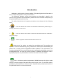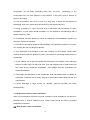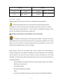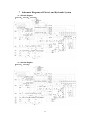
1
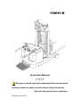
CY-SMS-001_EN Instruction Manual CY13 Operators should read and understand this manual and all warning Labels on power stacker before using the stacker. Keep the manual for future reference. Release: July. 2010 EG-Konformitätserklärung EC Declaration of Conformity Hiermit erklären wir, NOBLELIFT EQUIPMENT Jingyi Road, Changxing, Zhejiang, China We herewith declare Daß die nachfolgend bezeichnete Maschine aufgrund ihrer Konzipierung und Bauart sowie in der von uns in Verkehr gebrachten Ausführung den einschlägigen grundlegenden Sicherheits- und Gesundheitsanforderungen der EG-Richtlinien entspricht. that the following machine complies with the appropriate basic safety and health requirements of the EC Directive based on its design and type, as brought into circulation by us. Bei einer nicht mit uns abgestimmten Änderung der Maschine Erklärung ihre Gültigkeit. verliert diese In case of alteration of the machine, not agreed upon by us, this declaration will lose its validity. Bezeichnung der Maschine: Machine Description: Maschinentyp: Machine Type: Elektrohubwagen Power Stacker CY1316/CY1318/CY1330/CY1337/CY1345 Einschlägige EG-Richtlinien: EG-Maschinenrichtlinie: 2006/42/EC Applicable EC Directives: EC Machinery Directive: 2006/42/EC Angewandte harmonisierte Normen insbesondere: Applicable Harmonized Standards: EN 1726-1: 1999; EN1175-1: 1998 Herstellerunterschrift/Datum: Authorized Signature/Date: Dec. 29, 2009 Angaben zum Unterzeichner: Title of Signatory: President Table of Contents Introduction……………………………………………………………1 1 Guidelines for Safe Operation………………………………..….. 2 2 Technical Manual …………………………………………………6 3 Transport and Trial Run………………………………………… 9 4 Operation …………………………………………………………11 5 Maintenance, Recharging and Replacement of the Accumulator ……………………………………………………………………..17 6 Maintenance and Service Manual ………………………………22 7 Schematic Diagrams of Electric and Hydraulic System ………29 Introduction Welcome to use this series of power stackers. This manual gives clear information on how to master safe operation of the power stackers. The differences between various power stackers are described in detail in this manual. During operation and maintenance, please refer to the contents corresponding to the power stacker types you are using. The safety instructions and important precautions are indicated with the following icons: 1. ---- This icon indicates the existence of a hazard that could result in personal injury if the safety instruction is not observed. 2. ---- This icon indicates that a failure to observe the described instruction could lead to equipment damage 3. ---- Refers to general notes and instructions before use. Most parts of the product are made from recyclable steel. The recycling and disposal of cast-offs resulted during using, maintenance, cleaning and disassembling the product has to comply with local regulations without pollution to the environment. The recycling and disposal of the cast-offs should only be operated by specialised personnel in the designated area. The cast-offs such as hydraulic oil, batteries and electronic units, if improperly disposed, may be hazardous to the environment and human health. Due to continuous product improvement, Noblelift reserves the right to make changes in product designs and specifications without prior notice. For the latest product parameters, please feel free to contact us. Note: All parameters provided herein are as of the publication date of the Instruction Manual. 1 1 Guidelines for Safe Operation 1.1 Requirements for the driver: The stacker should only be operated by personnel trained in operating the stacker, who can show to the user how to move and handle loads and instruct the user how to operate the stacker. 1.2 The right, duty and responsibility of driver: Clear with his own right and duty, the driver should be trained in operating the stacker and also knows the contents in this operation manual very well. If the stacker in use is controlled on foot, the driver should wear safety boots during operation. 1.3 Unauthorized persons are prohibited to use: The driver is responsible for managing the stacker in use, and must prevent any unauthorized person from driving or operating the stacker. It’s prohibited to transfer and raise the person by the stacker. 1.4 Malfunction and Defects: In case malfunction or defects occurs with the stacker, the driver should immediately inform the supervisor. If the stacker can not be operated safely, e.g. with worn wheels and brake malfunction, always stop using it until repaired completely. 1.5 Safety operation and environment protection The checking and maintenance work described in this chapter should be executed according to the time intervals in the maintenance list. Never modify any parts, especially safety devices of the stacker without permission. Never change the operation speeds of the stacker. All original spare parts from the factory are verified by Quality Assurance Department. Only use spare parts from the manufacturer for the guarantee of the safety and reliability of stacker operation. The replaced material such as oil or fuel should be disposed of according to environment protection regulations. 1.6 Dangerous area: Dangerous area generally refers to these locations, in which pallet stacker or its lifting mechanism (e.g. fork or accessories) is moving, lifting or lowering, thus being dangerous to persons in this area, or in which the stacker is handling loads. Generally the scope of this area extends to locations to which the loads or accessories on the stacker is lowered. Unauthorized persons must be ordered to leave dangerous areas. The driver 2 should always give warning if there is any risk of human injury. If the warned persons still stay in dangerous area, the driver should stop the pallet stacker immediately. Use of this stacker may cause crushing and shearing injuries to personnel. 1.7 High-risk environment: Special protection measures shall be adopted in highly dangerous working environments. The stacker is not designed for use in high-risk environment. 1.8 Safety devices and warning signs:Sufficient attention should be paid to safety devices, warning signs and precautions described in above sections in this manual. 1.9 Driving in public places: The stacker is prohibited to drive in public places except for special areas. 1.10 Space between vehicles: Remember to keep a proper distance from the vehicle ahead, since it may stop suddenly at any moment. 1.11 Passengers: Never carry or lift persons with this stacker. 1.12 Headroom: Never use the stacker in areas where the headroom is lower than the height of loads or mast. 1.13 Operation in a lift or loading platform: If the load capacity of the lift or platform is sufficient and the space is enough for stacker operation, they can be used for transportation with the permission from the stacker user. The stacker must be confirmed by its driver himself before entering the lift or loading platform. When entering the lift, the loads must enter ahead. And locate the stacker in a suitable position to prevent from contacting walls around. If passengers take the lift together with the stacker, they have to enter after the stacker enters and stops firmly, and leave before the stacker. 1.14 Driving passageway and working area: The stacker must be driven in designated passageway. Non-related persons must leave the working area. Loads must be stacked in designated locations. 1.15 Operation Management: Driving speeds must be suitable to local conditions. Always drive in lower speed when passing curved passageways, narrow passageways, rotary doors or any obstructed places. The driver should be able to measure by sight and keep enough stopping space from vehicles ahead all the time. It is prohibited to make 3 an abrupt stop (unless in emergency), rapid U-turn and chase with each other in obstructed places. Never operate the stacker with the body stretching out of it. 1.16 Visibility: The driver must keep his eyes on moving direction and have a clear view of the road ahead. In case the loads carried block sight of the driver, another person should walk in front of the stacker, giving corresponding guidance and warning to the driver. 1.17 Passing a ramp: Only known ramps are permitted to pass. And the ramps must be clean, anti-skid and meet specification requirements of the stacker. Loads on the fork must face the upward slope. Never turn around, drive obliquely or stop on a slope. Pass a ramp in lower speed and get ready for braking at any time. 1.18 Load capacity of the floor: Check if the weight of stacker and loads or wheel pressure on the floor exceeds the load capacity of the floor. 1.19 Transportation: The fork should be kept lower than 300mm from the floor during non-transportation driving. It is better to driver in reverse direction of the fork to get good vision and mobility. Driving with the fork forward may cause unpredictable mobility problems. 1.20 Speed: Select a suitable speed, depending on floor conditions, visibility and the principle of safety operation. During operation, it is prohibited to speed up, stop and turn suddenly, for that may cause roll-over of the loads and the stacker. 1.21 Driving on loading platform or approach bridge: Before driving the stacker onto loading platform or approach bridge of a truck, make sure to check load capacity of the approach bridge and if it is equipped with anti-sliding devices. The driver must also check load capacity of the truck and if there are devices to prevent the truck from moving. 1.22 Safe Parking: Pay attention to safety when parking the stacker. Never park the stacker on a slope or on a ramp. The fork must be lowered down to the lowest position after parking. Turn off the electric lock and remove the key to prevent unauthorized operation. Please disconnect the wires linked to batteries, if the stacker will not be used for a long time before recharging, Please disconnect the wires linked to batteries, if the stacker will not be used for a long time before recharging. 1.23 Signalling: Warning signals can be sent by the horn on the stacker. 1.24 Protection shoes: According to EU standard EN-345:1-S1, standard protective shoes must be worn when operating on the stacker. 4 1.25 Truck modification:Unauthorized truck modification is not permitted. No modifications or alterations to a powered industrial truck, which may affect, for example, capacity, stability or safety requirements of the truck, shall be made without the prior written approval of the original truck manufacturer, its authorized representative, or a successor thereof. When the manufacturer or its successor approve a modification or alteration, they shall also make and approve appropriate changes to capacity plate, decals, tags and operation and maintenance handbooks. Only in the event that the truck manufacturer is no longer in business and there is no successor in the interest to the business, the user may arrange for a modification or alteration to a powered industrial truck, provided, however, that the user shall: a) arrange for the modification or alteration to be designed, tested and implemented by an engineer(s) expert in industrial trucks and their safety; b) maintain a permanent record of the design, test(s) and implementation of the modification or alteration; c) approve and make appropriate changes to the capacity plate(s), decals, tags and instruction handbook; d) affix a permanent and readily visible label to the truck stating the manner in which the truck has been modified or altered together with the date of the modification or alteration, and the name and address of the organisation that accomplished the tasks. 5 2 Technical Manual This series of stacker CY are designed for short and medium distance heavy-duty transportation on flat road surface. 2.1 Specifications Type No. Rated Loading Capacity CY13 kg 1300 Load centre distance mm 600 Lift height mm 1600-4500 Travel speed, unladen km/h 6 Travel speed, laden km/h 5.4 % Gradient performance, laden Turning radius Wa(mm) 1450-1600 φ210×85 Tyre size, side wheel Drive motor power Lift motor power 5 kw 1.8 kw 2.2-3.0 Sound level at driver's ear acc. to EN12053 dB(A) dB(A) 67 CY13 6 A(mm) B(mm) 1850-2275 C(mm) 200-720 D(mm) 1104 E(mm) 537-772 F(mm) 950-1150 G(mm) 550-580 2025-2400 These tables provide only specifications of standard stackers according to VDI 2198. Specifications of non-standard stackers or stackers equipped accessories or other optional components may be different from above tables. We reserve the right to update the specifications of this stacker. 2.2 Technical Standards Continuous noise level should be less than 70dB(A) according to ISO4871 standard. Continuous noise level is an average value of noise measured at the driver’s ear during travelling, lifting and being standby. Electromagnetic Compatibility (EMC) The manufacturer confirms that the stacker complies with EN12895 and other relevant standards on limits of electromagnet radiation and interference, and has been tested on static discharge. Never modify any part of electrical system without written permission from the manufacturer. 2.3 Operation Conditions Ambient temperature: 5℃~40℃ Special devices have to be used under a temperature below 5℃ or in very humid environment. Altitude: up to 2000m. If there is quality problems with the stacker or you need to order spare parts, please specify serial number of the stacker and part number. 7 2.4 label No. Description QTY 1 Hook label 2 2 Warning label 2 3 Capacity label 2 4 CE label 2 8 Remarks 3 Transport and Trial Run 3.1 Transport with a crane Load capacity of the crane in use must be sufficient. The load weight equals the net weight of stacker plus weight of accumulator; see nameplate plate on the stacker. The hook holes are specially designed for transport the stacker. — Park the stacker in a safe position. — Hooks of the crane must be applied at hook holes. Hooks of the crane must be applied at hook holes, ensuring the stacker will not be slipped down. During operation, make sure the crane, whose hooks must be applied at hook holes of the stacker, do not contact with the stacker. 3.2 Trial Run The stacker can only use accumulator as power supply. Changing to use AC power will damage the electric circuit. Cables connecting accumulator should be less than six meters. To ensure the stacker work normally after delivery and transportation, following operations have to be completed: — Make sure all labels on the stacker are complete, clear and readable. If not, replace with new labels immediately. — Check if the completeness of all parts and components, and check if they are in compliance with requirements. — If necessary, install batteries without damaging the connection cable. — Recharge the accumulator immediately. — If customers want to replace the accumulator with a new one, make sure that the new accumulator match with the accumulator coulombmeter (or is permitted by service technician of manufacturer). 3.3 Towing of stackers without driving ability When towing the stacker without driving ability, release electromagnetic brake before moving. —Press emergency control button and turn the power supply switch to OFF position. —Open the cover of electric unit. 9 —Release 3 screws counter clockwise on the electric motor until the brake does not impede the stacker from moving. Now, you can tow the stacker. After arriving at the destination location, recover the stacker to original status. 10 4 Operation 4.1 Schematic diagram of the lever 1. Forward/Backward button 2. Slow Speed/drive button 3. Emergency reverse button 4. Horn button 4.2 Starting-up the stacker The driver should always make sure that no person stayed in dangerous area of the stacker before starting up and operating the unit or lifting loads. Check before daily start-up —Check the entire unit for defects and failure, especially the wheels and lifting mechanism. —Check if the accumulator is firmly fixed and well-connected. Starting-up the stacker — Turn on the emergency stop switch. — Insert the key in electric lock and turn it clockwise to position “I”. — The coulombmeter shows current battery level. — Check the horn. — Check braking function of the control lever. Now the preparation before starting-up is completed. It has certain risks to use the stacker in rainy, snowy, foggy and windy weather. Before use in those conditions, please evaluate the security. 4.3 Operation of the stacker 4.3.1 Starting-up, Driving and Parking Be careful during starting up and driving, especially when part of your body stretches out of stacker’s outlines. Do not carry any other person during driving. 11 Emergency Stop Pressing the emergency stop switch will stop all electric control functions. Forced Braking When the control handle is released, the stacker will brake automatically (emergently stop). The control handle will enter the upper braking range (B1) automatically. If the lever enters braking range slowly, make sure to find out its causes and troubleshooting the failure. If necessary, replace the air spring of the handle. Starting up Start up the stacker only when the battery cover is closed. Starting-up the stacker. Travelling speed is regulated with the “Forward/backward” button. Rotate the “Forward/backward” button to driving range “F”, and adjust the control lever in required direction, the stacker will move towards selected direction. B1 F B2 12 Driving Swing the control handle rightward or leftward to drive. Motorized hand and hand/rider trucks employing a steering tongue control that extends beyond the confines of the truck shall steer such that with the operator facing in the direction of travel, with the load end trailing, clockwise movement of the steering tongue shall steer the truck clockwise. When the stacker comes across an obstacle, the force applied to swing the lever should be smaller than driving in normal status. In such case, turn the steering wheel / arm carefully to break away from the obstacle by moving forward or backward. Driving on a slope Always keep loads face the downward slope when transport loads on a slope. Take following safety measures against the rolling down: With the control button in position “0”, quickly press the handle backward. The driver should release the handle as required to make the electromagnetic brake work automatically, controlling the speed and direction (if the driver find the stacker is rolling down). In case the stacker is rolling over, the operator should get away from the stacker right away. Braking The braking performance of the stacker depends on floor condition. The driver must be clear about this point. Three braking methods are available: 13 — Electromagnetic brake (control handle) — Use reverse current brake (Forward/backward button) — Brake with the sensor (i.e. release the lever to brake) Braking with the Electromagnetic Brake In case of an emergency, always stop the stacker only with electromagnetic brake (control lever). Turn up or down the control handle to braking range B1 or B2, the drive motor will be stopped mechanically. When the control handle is released, it will enter the upper braking range (B1) automatically. After the stacker is stopped, the electromagnetic brake works as parking brake. Braking with reverse current brake If the control system or driving power fails, braking with reverse current is possible. —Turn the “ forward /backward button” in reversed direction of driving until the stacker stops. —Release the “forward /backward button”. Braking by the inertia When the “forward /backward button” is released, it returns to position “0”, and brakes by inertia of the motor. The slowing down rate depends on the position of “forward /backward button”. If the “forward /backward button” position is set to ‘0’ and the inertia braking unit is removed by service technician, you have to use electromagnetic brake or reverse current brake to brake the stacker. 4.3.2 Operation of the forks It’s prohibited to stand under the fork when the fork is moving upward or downward, preventing crushing and shearing injuries to personnel. Before lifting loads, the driver must check if the loads are placed on the pallet completely and the weight of loads does not exceed the loading capacity. Do not transport in full load status for a long time. Make sure the fork reach under the loads as far as possible. When operate with “Up” 14 or “Down” button, the fork will move upward or downward at a fixed speed. Take the following steps to load heavy objects: 1. Drive the stacker right in front of the heavy object; 2. Push the right handle forward to downswing the fork, then adjust left handle (forward or backward) to place the fork to an appropriate height below the heavy object; For war d 3. Push the middle handle forward to extend the fork under Downward the heavy object; 4. Pull back the right handle to upswing the fork, so that the heavy object won't drop; then pull back the left handle to lift the fork, until the object is loaded. Manipulate the left handle to make the bottom of the goods higher than the stacker wheels (to avoid collision between the stacker and Downswing heavy object when the fork moves back). After that, pull the middle handle back to move the fork back. 5. Adjust the left handle to place goods to a lower position, Upswing so as to facilitate the stacker's normal running. Take the following steps to stack heavy objects: 1. Drive the stacker loaded with heavy object right in front of the the shelf; 2. Lift the heavy object to an appropriate height; (with the same method as above) 2. Move the fork forward to an appropriate height; (with the same method as above) 4. Push the left handle forward slowly to lower the heavy objects, and load the bottom of tray onto the shelf; 5. Downswing the fork and slowly move the fork out of the shelf. Then lower the fork and drive the stacker away from the shelf. Place the fork to the lowest position after use, then park the stacker in a safe and reliable place with even ground. Make sure that the stacker can be moved with manpower after being parked. Pull the key out and keep it properly. 15 If you need to install a back-rest, make sure its height, width and size of opening will minimize the possibility of loads falling against the fork. Back-rest shall not obstruct the view, and the size of its opening can not exceed 150mm. Safe Parking Pay attention to safety when parking the stacker. Never park the stacker on a slope or on a ramp. The fork must to be lowered to its lowest position after parking. —Lower the fork. —Turn electric lock from position “1” to “0” and remove the key. 16 5 Maintenance, Recharging and Replacement of the Accumulator 5.1 Safety procedures for lead-acid accumulator operation The stacker must be parked in a safe location before any operation on the accumulator. 5.1.1 Maintenance Technician Only qualified technician can perform operations on the accumulator such as recharging, maintenance and replacing. Before operation carefully read instruction manuals including operation manual, replenishment preparation and recharging requirements. 5.1.2 Fire Prevention Measures Never smoke or use open fire when perform operations on the accumulator. The accumulator should be away from flammable material at least two meters when storage or recharging. The location for accumulator storage should be well ventilated and equipped with fire fighting devices. 5.1.3 Maintenance of the Accumulator 1) Keep the nuts on every battery cell dry and clean. Tighten every terminal and cable end, and brush them with grease to prevent corrosion. Naked cable ends and terminal posts should be covered with a skid-proof insulating cover. 2) Every two cells should be well-connected. Check the nuts on each pole, if loose, tighten the nuts. 3) Keep the surfaces of accumulator clean and dry. After the completion of recharging, clean spilled acid with cotton yarns or brush. And clean with wet towel if necessary. 4) Over recharging and over discharging should be avoided, and fast charging and insufficient recharging are also not allowed. Otherwise life span of the accumulator may be affected. 5) Do not put conductive objects including metal tools on the accumulator, or short circuit or even explosion may be caused. 6) Never spill any hazardous liquid or solid material on surfaces of the accumulator. When using a densimeter or a thermometer, make sure the surface is clean and clear. 7) Recharge the discharged accumulator in time. Delayed recharging may damage the 17 accumulator. Do not delay recharging more than 24 hours. Recharging of the accumulator may not work outdoors in cold weather. In this case, move it indoors to perform recharging. 8) If the accumulator will not be in use for a long time, it should be recharged and discharged once every month and it should be fully recharged every time. 9) During recharging or using, the liquid level of electrolyte lowers because of water evaporation, so pure water should be added. It is not allowed to add electrolyte with a specific weight of 1.280. 10) If individual cell fails, identify the cause and repair the cell immediately. Replace the cell when it cannot be repaired. 11) The site for recharging should be well ventilated. It is prohibited to smoke or use open fire, avoiding the risk of hydrogen explosion. 12) The electrolyte in accumulator is toxic and corrosive. For this reason, always wear working suit and protection glasses to protect your body from contacting the electrolyte in accumulator. 13) If your clothes, skin or eyes are spilled with acid liquid in accumulator, flush with large amount of clean water. For skin and eyes, flush with large amount of clean water and also seek doctor’s treatment immediately. Acid spillage must be neutralized and treated immediately. 14) The weight and dimensions of the accumulator have remarkable effect on stability of the stacker. Therefore do not modify the type of accumulator without approval from the manufacturer. 15) Never discharge in large current, for example, performs travelling and lifting simultaneously. 5.1.4 Disposition of worn-out accumulators Worn-out accumulators should be recycled according to local regulations, and stored in specified zone or cast-off treatment zone. These works should be done by qualified specialized companies. 5.2 Specification of the accumulator 18 Battery Charger Rated power(V): 24V Rated capacity(Ah): Input:AC115/230V 270Ah 50/60Hz Output:DC24V/40A Rated power(V): 24V Rated capacity (Ah):400Ah Input:AC115/230V 50/60Hz Output:DC24V/50A Battery of 24V/270Ah should be used for CY1316、CY1318、CY1330;24V/400Ahshoudl be used for CY1337、CY1345。 Weight and dimensions can be found on the nameplate of the accumulator. Uninsulated terminal poles on the accumulator should be protected with an insulated cover. When connecting the accumulator and socket, make sure to stop the stacker and put the switch at position “0”.. When replace or install the accumulator, make sure the accumulator is fixed securely in battery box. 5.3 Storage, transportation and installation of the accumulator The stacker must be parked on the level ground steadily. To prevent short circuit, naked cable ends and the terminal posts should be covered with insulated covers. When pulling out the accumulator, properly arrange removed accumulator's connectors and cables without blocking access of the accumulator. When install or remove the accumulator with a crane, make sure the load capacity is sufficient (weight of the accumulator is marked on both the nameplates of the accumulator and the stacker.) The crane must pull vertically to prevent the battery box from being damaged. The hooks of the crane should be safe and secure. Never let the hooks fall on an individual battery . — Press emergency stop switch and turn the power supply switch to OFF position — Remove the connectors of accumulator cables. —Connect the lifting device to lifting holes. —Lift out the accumulator from the top and move away with handling equipment. 19 Perform installation in reverse order of above steps. It is noticeable to put the accumulator in right position and connect the cables securely. After reinstalling the accumulator, always check all cable connections and connectors for obvious damage. 5.4 Capacity indicator of the accumulator Capacity indicator of the accumulator The status of accumulator discharging is indicated on the indicator with 10 bar graphs, each bar represents 10 percent of increment. As the consumption of accumulator capacity, the lighting bars will fall down from the top. Preset “Warning” marks will appear when remaining capacity of accumulator meets following conditions: When the remaining capacity of the standard accumulator is 30 percent, “Warning” mark will appear and you can recharge the accumulator. Preset “Warning” mark and a flashing “Stop” mark will appear when remaining capacity of accumulator meets following conditions: When the remaining capacity of standard accumulator is 20%, “Stop” mark will appear and keep lighting. When the “Stop” mark keeps lighting, lifting function of the stacker will be cut off automatically. Capacity sufficient Recharging needed Low battery If the indicator shows low battery when lifting loads for a not very long period, lifting function can only be performed after recharging the accumulator to at least 70% of capacity. 5.5 Recharging The CY series of stackers is supplied with a special charger for recharging. Read the instruction manual carefully before recharging. The batteries should be recharged in well-ventilated areas. Make sure no metal objects placed on the accumulator. Check all cables connection and connectors for 20 obvious defects. Observe strictly all safety instructions, e.g. replenishment of the accumulator and preparation for recharging. Hydrogen will be precipitated in the charging process. So the accumulator room should be well-ventilated, and the hydrogen content shall be strictly controlled to ensure safety. For the safety of the cooperation, the stacker should be added protective cover before using. 5.5.1 Balanced Recharging After using for a period, voltage and concentration may vary from battery to battery. Balanced recharging will eliminate the differences so that the performance of each cell becomes uniformed. In following cases, balanced recharging is necessary: Voltage of an individual cell is frequently below 1.7V; large current occurs during discharging, for example, when using the driving motor and lifting motor simultaneously; for accumulators that are not recharged in time after discharging: Over discharged accumulators and those are not in use for a long time. Perform balanced recharging as follows: A、 Recharge with a current of 0.1I5A. B、 When the voltage up to 2.5V, and there occur bubbles in the electrolyte, continue recharging at a reduced current of 0.05I5A. C、 Recharge the accumulator to full capacity and stop recharging for half an hour, and then continue recharging with further-reduced current of 0.025I5A for an hour. D、 Stop recharging again for half an hour and continue recharging with a current of 0.025I5A for an hour. E、 Repeat step D until bubbles occurs intensely and instantly when switching on the charger. Perform balanced recharging to accumulator once a month in normal use. 21 6 Maintenance and Service Manual Never modify any parts, especially safety devices of the stacker without permission. Never change the operation speeds of the stacker. All spare parts provided by original manufacturer are strictly tested. Only use spare parts from the manufacturer for the guarantee of the safety and reliability of stacker operation. The replaced material including oil should be collected and disposed of according to local environment protection and health regulations. 6.1 Safety procedures for maintenance and service Maintenance technician: The maintenance and service should only be performed by special personnel trained by the manufacturer. After the technician sent by after-sales department of the manufacturer completed maintenance and servicing work, they should sign on the service log. Lifting of the stacker: When the stacker needs to be raised up for repair, the lifting device must be safe and reliable, and must be strictly fixed to hook holes. When the stacker is raised up, proper measures such as using wedges and wooden blocks must be applied to prevent the stacker from sliding down or tilting over. Cleaning Operation: Flammable liquid can not be used for cleaning the stacker. Before cleaning, take safety precautions to prevent electric sparks (e.g. sparks caused by short circuit). When operating the accumulator, connectors on it must be disconnected. Use soft air suction or compressed air, non-conductive and anti-static brushes to clean electric and electronic components. If you are going to use water spray or high pressure cleaner to clean the stacker, all electric and electronic components must be covered carefully in advance because moisture may cause them malfunction. Never use steam nozzles for cleaning. Operation of Electric System: Operation on the electric system should only be performed by specially trained personnel. Before performing any operation on the electric system, precautions must be made to prevent electric shock. When operating the 22 accumulator, connectors on it must be disconnected. Short-time duty for traction motor and lifting motor, driving motor:S2 60min,lifting motor: S3 15%。 Welding Operation: To prevent electric components from being damaged, remove these electric components before welding. Installation: When repairing or replacing hydraulic components, electric and electronic components, make sure to install them back to their original positions. Wheels: Quality of the wheels has significant effect on stability and driving performance of the stacker. Modification on wheels can be performed only with the approval from the manufacturer. When replacing wheels, ensure that the stacker is levelled as delivery state (wheels must be replaced in pairs, i.e. replace right wheel together with left one). Lifting chain and rollers: Chain and rollers will be worn quickly without good lubrication. Perform periodic lubrication according to following maintenance table. Shorten the lubrication period under adverse operation conditions (such as in dusty and hot environment). Hydraulic oil pipe: The oil pipe must be changed every 6 years. When change the hydraulic assembled parts, the oil pipe should be also changed. 6.2 Routine Maintenance (Before every shift) 6.2.1 Check the liquid level of electrolyte in the accumulator. The liquid level will be higher when being recharged. 6.2.2 Check every pole, every cable and their covers. 6.2.3 Check if the accumulator box is secured. 6.2.4 Check the stacker for oil leakage. 6.2.5 Check the chain, rollers, fork, oil pipes and horn. 6.2.6 Check the brake. 6.2.7 Check the wear and tear of drive wheels and loading wheels. 6.3 Professional Maintenance Manual It is very important for safe operation of the stacker to perform overall professional maintenance. Failure in performing maintenance according to specified interval may 23 cause malfunction of the stacker, and potential risk to human and equipment. Maintenance periods listed in this manual apply to single shift a day under normal operation conditions. If using in dusty environment, the ambient temperature varies remarkably or in multi-shift situation, the maintenance period has to be shortened. Maintain the stacker according to following maintenance list. Maintenance periods are as follows: W1 = Every 50 work hours, but at least once a week. M3 = Every 500 work hours, but at least once every three months M6 = Every 1000 work hours, but at least once every six months M12 = Every 2000 work hours, but at least once every 12 months Additional operations should be performed in trial run period: (In initial 50 – 100 working hours or after two months) — Check the nuts on the wheels, and tighten them if necessary. — Check the hydraulic components for leakage, and tighten them if necessary. —Replace the hydraulic filter. Maintenance List Chassis & Main frame Driver: Wheels: Steering system Braking system 1.1 1.2 2.1 2.2 2.3 3.1 3.2 4.1 5.1 5.2 5.3 Time interval of maintenance Standard W M M M =● Cooling 1 3 6 12 storage =# Check all bearing parts for damages ● Check all bolt connections ● Check the drive system for noise and leakage ● Check oil level in drive system ● Replace lubricant oil # ● Check for wear and tear ● Check the bearings and make sure they fit well with ● the wheels a) Check the steering control ● Check the performance and adjust accordingly Check reset function of the air spring, and check for leakage and damages Check the brake disk for wear 24 # ● ● ● 5.4 Lifting Mechanism 6.1 6.2 6.3 7.1 7.2 Hydraulic system 7.3 7.4 7.5 7.6 8.1 8.2 Electric system 8.3 8.4 8.5 Motor 8.6 9.1 9.2 9.3 10.1 Accumulator Lubricant oil General Test Trial 10.2 10.3 10.4 11.1 12.1 12.2 12.3 12.4 13.1 13.2 Check the connection of brake and adjust if ● necessary Check performance and wear, and adjust accordingly ● Visually inspect the loading wheels for blockage ● Check fork tips and pallet support for wear and # ● damages Check performance # ● Check all connections for leakage and damages # ● b) Check the cylinder for leakage and damages and if # ● the accessories are safe and secure Check the oil level. # ● Replace hydraulic oil and the filter element # c) Check the pressure regulator valve # Check performance ● Check all cable connections for safety, reliability and ● damages Check if the amperage of fuses is proper Check if the switches and release cam mechanism is ● secure and functions properly Check the connectors and replace worn parts if necessary Check the warning device # ● Check the carbon brush for wear ● Check safety of additional devices of motor ● Use a vacuum to clean motor frame. Check the # ● commutator for wear Check the density of acid liquid, capacity and voltage # ● of the accumulator Check the safety devices on terminals and the grease # ● Clean the connector of accumulator and check the # ● connection. Check the cable for damages, replace if necessary ● Grease the stacker according to time table for filling # ● up lubricant Check the grounding connection of electric system Check the travelling speed and braking distance Check the lifting and lowering speed Check the safety device and switch off devices ● Perform trial run under rated load ● The stacker is proved to be safe and reliable to # ● personnel after completion of above maintenance 100 working hours, check the nuts of wheels, tighten them if a) After about initial necessary. b) After about initial 100 working hours, check the hydraulic system connections for leakage and tighten it if necessary. c) After initial 500 working hours. 6.4 Service Manual 6.4.1 Troubleshooting 25 ● ● ● ● ● Fault The stacker can not move Cause Repair measures - Connectors on accumulator are not connected - Electric lock is in position “0” - Emergency stop switch is not turned on. - The accumulator capacity is in used up - Check the connectors on accumulator, connect them if necessary - Turn the Electric lock in position 1 - Turn on the emergency stop switch. - Check the capacity of accumulator, recharge if necessary - Turn the control lever to drive rage F - Check fuse FU01 and FU1 - The control lever is not in drive rage F - fuse blown - The stacker is not operating Loads can not be lifted up - Low hydraulic oil level - fuse blown - The accumulator has only 20/30% of capacity - The UP switch is in bad contact or damaged. - Dirty oil blocks control valve. Loads can not be lowered down It can not stop when lifting up - The solenoid valve for lowering is not opened or is damaged Do as methods in “The stacker can not move” table. - Check hydraulic oil - Check fuse FU02 and FU2 - Recharge the accumulator. - Check UP switch and replace if necessary. - Check hydraulic oil and clean control valve. Replace the oil if necessary. - Check or replace the valve for lowering - The UP switch is damaged. - Disconnect power supply and replace the UP switch Moving in one direction - The sensitive switch and the connecting cable are not well-contacted. - Check the sensitive switch in control lever and the connecting cable. The travels slowly. - The accumulator capacity is insufficient. Or the electromagnetic brake is tight. Or the related cables are not well-contacted. - Check the capacity indicator, the brake and related cables. - The controller is damaged. The button controlling backward or forward is not back to its normal position. — Replace the controller. - Repair or replace it. stacker very The stacker starts up suddenly If above steps still can not solve problems, please contact after-sales service department of the manufacturer and have the problems solved by specially trained technicians. 6.4.2 Preparation before repair 26 To prevent possible accidents during maintenance and repair work, following preparations must be done: — Park the stacker safely. — Press the emergency stop switch and disconnect the connectors on accumulator. When the fork needs to be lifted up or the stacker needs to be raised up for repairing, precautions for preventing the fork or the stacker from tilting over or falling down suddenly must be taken. For information on lifting of the stacker, see related parts in “Transportation and Trial Run” above. 6.4.3 Check hydraulic oil level — Get the stacker ready for maintenance or repairing. — Open the cover of electric unit. — Check hydraulic oil level in oil tank. Check the hydraulic oil level only after the fork and main frame are lowered to their lowest position. 6.4.5 Use Preparation after maintenance or repairing Use the stacker only after following operations have been completed. — Clean the stacker. — Check the brake. — Check the emergency stop switch. — Check the horn. 6.5 Storage of the stacker If the stacker will be not in use for over two months, it must be stored in antifreeze and dry locations. Take protection measures before storing. If the storage time is over six months, please consult the manufacturer on additional protection measures. During storing, the stacker should better be placed with the wheels off the ground for protecting the wheels and the bearings within wheels. 6.5.1 Operations before storing — Clean the stacker thoroughly. — Check the brake. — Check the hydraulic oil level, refill if necessary. — Apply lubricant oil or grease to protect all parts. 27 — Refill grease according to detailed lubrication cycle table. — Recharge the accumulator again. — Disconnect and clean the accumulator. Apply grease on terminal poles on accumulator. Besides these, the accumulator must be protected according to special requirements stated in accumulator instruction manual. 6.5.2 Cautions during storage Every one month: Recharge the accumulator. Operations related to accumulator It is very important to recharge the accumulator periodically. Otherwise, the accumulator will self discharge, resulting complete loss of capacity and the accumulator may become worn-out thoroughly. 6.5.3 Trial Run Again — Clean the stacker thoroughly. — Refill grease according to lubrication cycle table. — Clean the accumulator, apply pole lubricant on the terminal poles and reconnect the connectors. — Recharge the accumulator again. — Check if there is moisture in gearbox oil. If so, replace gearbox oil. — Check if there is moisture in hydraulic oil. If so, replace hydraulic oil. — Start up the stacker. If the switches in electric system do not contact well, clean all exposed connectors with contact detergent spray, and repeat this operation to remove oxide layer on these connectors. Perform several electromagnetic brake tests immediately after trial run again. 28 7 Schematic Diagrams of Electric and Hydraulic System 7.1.1 Circuit diagram (CY1316、CY1318、CY1330) 7.1.2 Circuit diagram (CY1337、CY1345) 29 Following are names of electric components GB Accumulator 17 2 B+ Positive pole of accumulator. 18 P Capacity indicator 3 B- Negative pole of accumulator. 19 KMP Contactor of pump motor 4 Mp Pump motor 20 YV Solenoid valve for lowering 5 FU01,FU02,FU1, FU2 Fuse 21 HA Horn 6 BE Accelerator 22 Et Controller 7 Mt Traction motor 23 VD Diode 8 S1 Lowering button 24 S Emergency stop button 9 S2 Lifting button 25 KM Contactor of traction motor 10 S3 Steering button 26 SY Key switch 11 S4 reclining button 27 SHH Modular Switches 12 S5 Horn Button 28 SH Modular Switches 13 S6 Emergency reverse switch 29 A1,A2,A3,A4 Circuit board 14 S7 Timing shift knob 30 SU Lifting limit switch 15 SA Interlock switch 31 B Handle 16 X Connector 32 Kr Protection module 30 YB Electromagnetic brake 1 7.3 Schematic diagram of hydraulic system 31