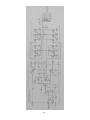
1
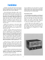
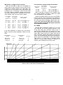
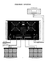
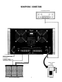
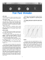
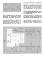
THE MclNTOSH MC 2300 SOLID STATE STEREO POWER AMPLIFIER
Price $1.25
The Mclntosh MC 2300 is a high quality, extremely high power, solid state stereo amplifier. Because of the high power available it is
necessary to emphasize some prudent and
safe operating conditions.
1. Never connect or disconnect inputs or
outputs while the amplifier is turned on.
Loudspeakers can be damaged or destroyed by the high power available from
the instrument.
2. Never operate the amplifier with the power
cord plugged into an auxiliary AC power
outlet on source equipment. The amplifier
draws near 14 amperes at full power and
damage to the source equipment can
occur.
3. Do not operate the instrument plugged
into an ordinary extension cord. Heavy
duty extension cords (14 ga. or heavier)
have adequate wire size and will not overheat.
4. Be cautious when lifting the instrument.
It weighs 128 pounds. Make certain that
what it is placed on can support the
weight.
Your MC 2300 Stereo Power Amplifier
will give you many years of pleasant
and satisfactory performance. If
you have any questions concerning
the operation or maintenance of
this instrument, please contact:
CONTENTS
GUARANTEE....
INSTALLATION....
CUSTOMER SERVICE
1
3
HOW TO CONNECT....4,5
Stereophonic.... 6
Monophonic.... 7
Mclntosh Laboratory Inc.
2 Chambers Street
Binghamton, New York 13903
Phone: 607-723-3512
FRONT PANEL
INFORMATION....
8
PERFORMANCE LIMITS.... 9
TYPICAL PERFORMANCE C H A R T S . . . . 1 0
TECHNICAL DESCRIPTION....11
Take Advantage of 3 years
of FREE Factory Service . . .
Fill in the Application NOW.
BLOCK D I A G R A M . . . . 1 6
GUARANTEE
Mclntosh Laboratory Incorporated guarantees this
Instrument to be capable of performance as advertised. We also guarantee the mechanical and electrical workmanship and components to be free of
defects for a period of 90 days from date of purchase. If such defects occur, Mclntosh Laboratory
or one of its authorized agencies wilt repair the
defect at no cost to the purchaser. This guarantee
does not extend to components damaged by improper use nor does it extend to transportation to
and from the factory or service agency.
An application for a FREE THREE YEAR FACTORY
SERVICE CONTRACT is included with this manual.
The terms of the contract are:
4. The SERVICE CONTRACT is issued to you as the
original purchaser. To protect you from misrepresentation this contract cannot be transferred to a
second owner.
For Three Years from date of purchase —
1. Mclntosh will provide all parts, materials and
labor needed to return the measured performance
of the instrument to the original performance
limits free of any charge. The SERVICE CONTRACT does not cover any shipping costs to and
from the authorized service agency or the factory.
5. The SERVICE CONTRACT is given to purchasers
who live In the 50 United States or Canada only.
6. For your protection Mclntosh selects Its dealers
carefully. Only one dealer in ten qualifies for a
Mclntosh franchise. To receive the SERVICE
CONTRACT your purchase must be made from a
Mclntosh franchised dealer.
2. Any Mclntosh authorized service agency will repair all Mclntosh instruments at normal service
rates. To receive the free service under the terms
of the SERVICE CONTRACT, the SERVICE CONTRACT CERTIFICATE must accompany the instrument when taken to the service agency.
7. Your completely filled In application for a SERVICE CONTRACT must be postmarked within 30
days of the date of purchase of the instrument.
8. To receive the SERVICE CONTRACT all information on the application must be filled in. The
SERVICE CONTRACT will be issued when the
completely filled in application is received at
Mclntosh Laboratory Incorporated in Binghamton,
New York. If the application is not received at
Mclntosh Laboratory, only the service offered
under the 90-day guarantee will apply.
3. Always have service done by a Mclntosh authorized service agency. If the instrument is modified
or damaged, as a result of unauthorized repair the
SERVICE CONTRACT will be cancelled. Damage
by improper use or mishandling is not covered by
the SERVICE CONTRACT.
2
Copyright © 1971 by Mclntosh Laboratory, Inc.
Installation
rails are attached to the front panel by 8 #10-32
machine screws and to each side by 4 small clips.
Remove both the front panel screws and the four
clips from each side for cabinet mounting. The opening to fit the unit is 17¼ by 10¼ inches.
Installation of the MC 2300 requires careful thought
about three important factors. They are the electrical
power to operate the unit, the weight and the heat
generated when the MC 2300 is operating.
The MC 2300 draws 1400 watts or about 14 amperes when operated at full power. Do not use ordinary extension cords of any type. Heavy duty extension cords (14 ga. or heavier) have adequate wire
size and will not overheat. Plug the AC power cord
directly into a wall outlet. Make certain that the AC
power outlet has at least 15 amperes capacity with
nothing else using the circuit. Do not plug the MC
2300 into an auxiliary AC power outlet on a preamplifier or other source equipment. If remote power
operation is required, an external relay arrangement
must be made.
RACK INSTALLATION
The MC 2300 may be mounted in a standard 19"
rack by removing the aluminum side rails. If a standard rack is used, the screws that held the aluminum
rails to the front panel are used to attach the MC
2300 to the rack. When rack mounted, the MC 2300
requires 10½ inches of panel space. Allow two
inches in front of the panel for the knobs. A depth of
17 inches plus ventilation space is required.
The MC 2300 can be slide mounted in a rack.
Tapped well nuts and internal structure bracing has
been added to both sides of the MC 2300 for use
with the Model CTS-116 side mounted slide assemblies manufactured by Chassis-Trak Inc., Indianapolis, Indiana.
Weight of the instrument is 128 pounds. Make
certain that the shelf on which it is to be mounted
can support that weight. If it is to be vertically
mounted, be certain the structure is capable of supporting the MC 2300.
Adequate ventilation extends the trouble-free life
of electronic instruments. It is generally found that
each 10° centigrade (18° F) rise in temperature reduces the life of electrical insulation by one half.
Adequate ventilation is an inexpensive and effective
means of preventing insulation breakdown that results from unnecessarily high operating temperatures. The direct benefit of adequate ventilation is
longer, trouble-free life. Provide a source for input
air and an outlet for the heated air. The heat generated in the operation of the MC 2300 is exhausted
from the unit by two low noise, long life fans.
Cooling input air is drawn into the MC 2300
through the ventilation holes on the sides of the
MC 2300. The air passes over the tranformers, output
heat sinks and transistors; and, is blown out the back
of the instrument by the two fans. It is recommended
that at least 2 inches of clear space be provided on
each side.
To permit the fans to operate best, provide at least
5 inches of space at the rear of the instrument. A
source for input air and a means to exhaust the
heated air is necessary so that the heated air does
not recirculate through the MC 2300.
To install the unit in a cabinet the aluminum side
rails with the feet attached must be removed. The
3
How to Connect
operation it is not necessary to use the same impedance loudspeaker on each output. Connect each
channel for the impedance desired.
INPUT
Stereo or twin amplifier operation:
Use shielded cables to connect the signal from the
preamplifier or signal source to the power amplifier.
All connection are made on the back panel of the
MC 2300.
When multiple speakers are to be connected to
either or both outputs, the combined load impedance
must be calculated and the load connected to the
appropriate impedance tap. The following table will
aid in selecting the correct impedance match.
For stereo operation the LEFT OUTPUT of the preamplifier should be connected to the LEFT INPUT of
the power amplifier. The RIGHT OUTPUT of the preamplifier should be connected to the RIGHT/MONO
input of the power amplifier. In stereo or twin amplifier operation the MODE SWITCH must be in the
stereo position.
Load
impedance
in ohms
0.4 to 0.9
0.9 to 1.8
1.8 to 3.6
Connect
to
0.5
1
2
Load
impedance
in ohms
Connect
3.6 to 7.2
7.2 to 14.4
14.4 to 28
4
8
16
to
If a load impedance is used that is lower than the
output impedance tap, then reduced power and possible distortion will result. If a load impedance is used
that is higher than the output impedance tap, then
neither the signal nor the amplifier will be harmed but
the voltage available is limited to that stated at that
tap.
For twin amplifier operation a separate signal
source can be connected to each input.
To minimize the possibility of hum the shielded
leads shall be run parallel or loosely twisted together. Locate the cables away from AC power cords.
For constant voltage line operation:
Monophonic or Single Channel operation:
25 volts
70 volts
A shielded cable from the signal source is connected to the RIGHT/MONO input of the MC 2300.
The MODE SWITCH on the back panel of the amplifier must be placed in the MONO position. In the
MONO position the output of the right channel input
amplifier is fed to both left and right power amplifiers.
The LEFT INPUT is disconnected. Only the signal fed
into the RIGHT/MONO input will be amplified. Should
the MODE SWITCH be left in the STEREO position
and the output transformers be strapped to a monophonic load, one channel will attempt to drive the
other and cause high circulating currents and overheating. Be certain that the MC 2300 is never operated in the stereo mode with the outputs connected
for monophonic operation.
Connect to 2 ohms
Connect to 16 ohms
Make all speaker connections at the amplifier only.
For multiple speaker operation, parallel the leads
from the speakers to the amplifier.
Because of the high power available from the MC
2300, be sure to use large diameter speaker leads. In
all cases, the leads to and from the speaker should
be twin conductor or twisted together.
Use lamp cord, bell wire, or wire with similar type
of insulation to connect the speakers to the amplifier. For the normally short distances of under 20 feet
between the amplifier and speaker #18 wire or larger
can be used. For distances over 20 feet between the
amplifier and speaker use larger diameter wire. Select the correct size wire for the wire distance from
the chart.
OUTPUT
Stereo or twin amplifier operation:
It is recommended that the DC resistance of the
speaker leads not be over 5% of the load impedance.
Up to 10% can be tolerated. Resistance of the leads
should be computed for the length of wire both to
and from the speaker or speakers.
To connect the left speaker first check the impedance of the speaker which is usually identified on
the speaker itself or in the owner's manual. Connect
one lead from the common terminal of the speaker to
the LEFT CHANNEL OUTPUT terminal strip screw
COMmon. Connect the other terminal of the speaker
to the screw with the number corresponding to the
speaker impedance on the LEFT CHANNEL OUTPUT
terminal strip. The right channel speaker is connected in the same manner on the RIGHT CHANNEL
OUTPUT terminal strip. For stereo or twin channel
4
Monophonic or Single Channel operation:
For monophonic constant voltage line operation:
When the MC 2300 is used as a monophonic or
single channel power amplifier the two channels are
combined to produce output up to 600 watts. The
output must be tied together at the appropriate load
impedance tap. In connecting a load to the MC 2300
for single channel operation connect the common
side of the load to the LEFT CHANNEL OUTPUT terminal marked COM., the other lead as below.
If the speaker
or load
Impedance Is:
The hot side
of the line Is
connected to:
0.25 ohms
0.5 ohms
Left 0.5
Left 1
Left 0.5 and Right 0.5
Left 1 and Right 1
2
4
8
Left 4
Left 8
Left 16
Left 4
Left 8
Left 16
ohms
ohms
ohms
If the output
voltage is:
25 volts
70 volts
and Right 4
and Right 8
and Right 16
0.4 to 0.9
0.9 to 1.8
1.8 to 3.6
WIRE GAUGE
0.5
1
2
22
Connect to
3.6 to 7.2
7.2 to 14.4
14.4 to 28
4
8
20
Left 2 and Right 2
Left 16 and Right 16
Should the MODE SWITCH be left in the STEREO
position and the output transformers be strapped to
a monophonic load, one channel will attempt to drive
the other and cause circulating currents and overheating. Be certain that the MC 2300 is never operated in the stereo mode with the outputs connected
for monophonic operations.
Connect a jumper
wire between:
Load Impedance
in ohms
Left 2
Left 16
Connect a jumper
wire between
Make all speaker connections at the amplifier only.
For multiple speaker operation, parallel the leads
from the speakers to the amplifier.
AC POWER
The MC 2300 is designed to operate on 117 to 130
volts 50/60 Hz. Do not use ordinary extension cords
of any type. Heavy duty extension cords (14 ga. or
heavier) have adequate wire size and will not overheat. Plug the the AC power cord directly into a wall
outlet. Make certain that the AC power outlet has at
least 15 ampere capacity with nothing else using the
circuit. Do not plug the MC 2300 into an auxiliary AC
power outlet on a preamplifier or other source equipment unless it is known there is adequate current
capacity. If remote power operation is required, an
external relay arrangement must be made.
If the load impedance is between any of the above
figures seclect the best impedance match from this
chart:
Load Impedance Connect to
in ohms
The hot side
of the load is
connected to:
16
16
18
14
12
10
8
6
0
50
75
100
150
200
LENGTH IN FEET OF TWO-CONDUCTOR SPEAKER WIRE
5
250
300
STEREOPHONIC CONNECTIONS
PROGRAM SOURCE
TO 120 VAC
DO NOT CONNECT LINE
CORD INTO PREAMPLIFIER
AC OUTLETS.
IF REMOTE POWER
CONTROL IS NEEDED
USE AN EXTERNAL
RELAY.
LEFT SPEAKER ML 4 C
6
RIGHT SPEAKER ML 4 C
MONOPHONIC CONNECTIONS
PROGRAM SOURCE
To 120 VAC
DO NOT CONNECT LINE
AC OUTLETS.
IF REMOTE POWER
CONTROL tS NEEDED USE
AN EXTERNAL RELAY.
MODE SWITCH
MONO
ML 4 C LOUDSPEAKER
7
STERE0
Front Panel Information
Monitoring of the output power is done at the primary or input of the autoformer resulting in true
power readings regardless of output impedance
selected.
LEFT GAIN
The left gain control is used to control gain or volume
of the left channel. Clockwise rotation increases gain.
RIGHT/MONO GAIN
The graph represents the relationship between the
meter reading and power output for all three meter
ranges:
In stereo the RIGHT/MONO GAIN control determines the gain or volume of the right channel only.
Clockwise rotation increases gain. If the MC 2300 is
connected as a monophonic or single channel amplifier, the gain or volume is controlled by the RIGHT/
MONO GAIN control.
Both controls have a standard volume control
taper. The numerals around the controls are provided
for reference. They do not represent relative output
versus rotation.
METER RANGE
The meter switch has four positions. The first position is OFF. With switch in the OFF position there is
no indication on the meters.
0: In this position of the meter range switch, the
amplifier will deliver 300 watts when the meter indicates + 3 dB, with meter indication of "0," the
amplifier delivers 150 watts, with a meter indication
of —3 dB, the amplifier delivers 75 watts.
—10: In this position of the meter range switch,
the amplifier will deliver 15 watts output when the
meter indicates "0."
—20: In this position of the meter range switch,
the amplifier will deliver 1.5 watt when the meter
indicates "0."
POWER
The power switch turns the MC 2300 on or off. If
you wish to control the on/off operation of the amplifier remotely, use a control relay in series with the
power line and leave the power switch in the ON
position. Do not plug the MC 2300 into any of the
auxiliary AC power outlets of the preamplifier or
other associated equipment unless that equipment
has power capacity for handling 1400 watts (14 amperes).
Two meters monitor and indicate the output power
in each channel. The meters indicate peak power output of the monitored channel. To assure more accurate indications of peak power, Mclntosh's peak locking circuits stretch the peak reading of rapid changing information long enough to give adequate visual
perception. Ordinary meters lack the capability of indicating the short interval of power in a sound wave.
The mass of the meter movement is too great to respond to the nearly instantaneous changes in music
program material. Mclntosh has developed circuits
that permit the meters of the MC 2300 to respond to
the short interval power in a sound wave to an accuracy of 98%.
8
Performance Limits
12 Hz to 35,000 Hz, +0 - 1.5 dB at one-half rated
power
NOISE AND HUM
90 dB below rated output
PERFORMANCE GUARANTEE
Performance Limits are the maximum deviation
from perfection permitted for a Mclntosh instrument.
We promise you that the MC 2300 you buy must be
capable of performance at or exceeding these limits
or you qet your money back. Mclntosh is the only
OUTPUT POWER MONITOR METER
Meter is calibrated to read +3 db when amplifier produces 300 RMS watts or 600 peak watts.
Meter range switch is provided to increase meter
sensitivity by 10 dB or 20 dB.
POWER OUTPUT
STEREO: 300 watts continuous, both channels operating; which is:
12.2 volts RMS across 0.5 ohm
17.3 volts RMS across 1 ohm
24.5 volts RMS across 2 ohms
34.6 volts RMS across 4 ohms
49.0 volts RMS across 8 ohms
69.3 volts RMS across 16 ohms
Meter features special circuit to respond to peak
values of complex input signal. Calibration accuracy
at 0 dB is ±2% at all frequencies; meter range accuracy is ±5%.
OUTPUT IMPEDANCE
Stereo: 0.5, 1, 2, 4, 8, and 16 ohms
Mono: 0.25, 0.5, 1, 2, 4, and 8 ohms
OUTPUT VOLTAGES
25 volts, stereo and mono; 70 volts, stereo and
mono
MONO: 600 watts continuous; which is:
12.2 volts RMS across 0.25 ohm
17.3 volts RMS across 0.5 ohm
24.5 volts RMS across 1 ohm
36.6 volts RMS across 2 ohms
49.0 volts RMS across 4 ohms
69.3 volts RMS across 8 ohms
DAMPING FACTOR
27 at 0.5 ohm output, 50 at 1 ohm output, 29 at 2
ohm output, 21 at 4 ohm output, 14 at 8 ohm output.
INPUT IMPEDANCE
200,000 ohms
INPUT SENSITIVITY
0.5 volts input required to produce rated output.
Level control provided for input voltages up to 30
volts.
HARMONIC DISTORTION
Stereo:
Less than 0.25% at 300 watts output from 20 Hz
to 20,000 Hz both channels operating. Typical performance is less than 0.1% at rated power. Distortion decreases as output power is reduced.
POWER REQUIREMENTS
120 volts, 50/60 Hz, 160 watts at zero signal output. 1400 watts at rated output.
Mono:
Less than 0.25% at 600 watts output from 20 Hz to
20,000 Hz. Typical performance is less than 0.1%
at rated power. Distortion decreases as output
power is reduced.
SEMICONDUCTOR COMPLEMENT
46 Silicon transistors, 22 Silicon rectifiers and
diodes
INTERMODULATION DISTORTION
Stereo:
Less than 0.25% if instantaneous peak power is
600 watts or less per channel with both channels
operating for any combination of frequencies 20
Hz to 20,000 Hz.
MECHANICAL INFORMATION
SIZE: Front pane! measures 19 inches wide (48.26
cm) by 10½ inches high (26.67 cm). Chassis measures 17 inches wide (43.18 cm) by 10 inches high
(25.4 cm) by 17 inches deep (43.18 cm), including
connectors. Clearance in front of mounting panel including knobs 2 inches (5.08 cm)
Mono:
Less than 0.25% if instantaneous peak power is
1200 watts or less for any combination of frequencies 20 Hz to 20,000 Hz.
FINISH: Front panel is anodized gold and black.
Chassis is black baked enamel.
FREQUENCY RANGE
Stereo:
MOUNTING: Standard 19" (48.26 cm )rack mounting.
20 Hz to 20,000 Hz, +0 - 0.5 dB at rated power;
1, 4, 8 or 16 ohms
20 Hz to 20,000 Hz, + 0 - 1 . 0 dB at rated power;
0.5 and 2 ohms
12 Hz to 35,000 Hz, +0 - 1.5 dB at one-half rated
power
WEIGHT: 128 pounds (58.06 kg) net, 143 pounds
(64.86 kg) in shipping carton.
SPECIAL FEATURES: The amplifier is completely
stable when connected to any loudspeaker system
and to any reactive loads. The MC 2300 has special
circuits to prevent damage by short circuit or open
circuit of the output loads, or by any amount of output impedance mis-match.
Mono:
20 Hz to 20,000 Hz, +0 - 0.5 dB at rated power;
0.5, 2, 4 or 8 ohms
20 Hz to 20,000 Hz, + 0 - 1 . 0 dB at rated power;
0.25, and 1.0 ohms
Thermal cutouts are mounted on the output transistor heat sinks to provide protection in the event of
inadequate ventilation.
9
HARMONIC DISTORTION vs. POWER OUTPUT
Typical
Performance
Charts
.5
.4
.3
.2
.1
0
.1
1
10
100
1K
POWER OUTPUT IN AVERAGE WATTS
POWER BANDWIDTH
400
360
320
280
240
200
160
120
80
40
0
10
100
1000
FREQUENCY HERTZ
10K
100 K
100
1000
INTERMODULATION DISTORTION
.7
.6
.5
.4
.3
.2
.1
0
.1
1
10
POWER OUTPUT IN EQUIVALENT AVERAGE WATTS
10
Technical Description
at frequencies above 50,000 Hz. This increased feedback reduces the noise level of the input section
where the signal to noise level is more critical, it also
rolls off the frequency response above 50,000 Hz.
Resistors R9 and R10 with C5 C6 form a filter chain
to filter the ± 21 volts used to supply the input amplifier. Left and right channels operate identically.
The output of the left and right input amplifiers is fed
to the mono/stereo switch.
Each channel of the MC 2300 can be divided into
five different sections. These sections are (1) input
amplifier, (2) power amplifier circuit, (3) limiter circuit, (4) meter circuit and (5) power supplies.
INPUT AMPLIFIER
OPERATION OF MONO/STEREO SWITCH
The MC 2300 will deliver rated output from an input signal of 0.5 volts. The input control reduces the
amount of signal into the input amplifier as the setting is reduced. By the correct setting of the control
input signals on the order of 30 volts can be applied
to the input of the MC 2300 without overdriving the
input. At the input amplifier two NPN transistors, Q2
and Q4, are connected in a differential amplifier arrangement. The two inputs to the differential amplifier
are the input signal and the feedback signal from the
output of the input amplifier. The use of a differential
amplifier provides the most efficient use of larger
amounts of negative feedback to maintain low noise
and distortion. The combined output of the differential amplifier feeds a common emitter voltage amplifier Q6. The output of the Q6 is coupled via a large
value capacitor to the power circuit and to the feedback input of the differential amplifier. A large value
capacitor is used to assure good low frequency reproduction and to assure that no DC is coupled to
the power amplifier circuits. From the collector of
Q6 the resistors R20 and R18 form a dividing network
which determines the amount of negative feedback
fed to the differential amplifier. The path provides
both AC and DC feedback. A small trimming capacitor parallels R20 to increase the amount of feedback
If the MODE switch is in the STEREO position
each input amplifier is directly connected to its respective power amplifier. In the MONO position the
output of the right channel input amplifier is fed to
both left and right power amplifiers, the LEFT INPUT
is disconnected. For stereo or twin channel operation the MC 2300 has two independent amplifying
sections. Consequently, each amplifier output can be
loaded with any desired impedance load. For MONO
operation the two power amplifier output sections
are connected together for parallel operation. The
output load therefore must be connected to the output of each channel strapped together in parallel.
Should the MODE switch be left in the STEREO
position and the output transformers be strapped to
a mono load, one channel will attempt to drive the
other and cause high circulating currents and overheating. Be certain that the MC 2300 is never operated in the stereo mode with the outputs strapped
in parallel.
POWER AMPLIFIER
At the right input channel power amplifier input,
two PNP transistors (Q102 and Q104) are connected
in a differential amplifier configuration. As in the
11
12
trol the positive portion of the output signal while
transistors Q118, 122, 126, 130, 134, 138 control the
negative half of the output signal. These 12 output
transistors work together forming a series push-pull
output capable of delivering extremely high currents.
The output transistors are mounted on oversized
black anodized heat sinks. Two long life quiet running fans draw air over the heat sinks and out the
rear of the unit. With all covers in place the MC 2300
will run relatively cool even under full load conditions. Resistor R112 completes the DC negative feedback path to the differential input while the resistors
R112 and R106 form a voltage divider network for
the AC negative feedback.
input amplifier the two signals to the differential
amplifier are the normal power amplifier input signal and the negative feedback signal from the power
amplifier output. The combined output of the differential amplifier feeds transistor Q106 which is a
common emitter Class A linear voltage amplifier. The
output of Q106 is directly coupled to the bases of
transistors Q112 and Q118 which are NPN and PNP
complementary medium power driver transistors. The
driver stages furnish the current required to the
bases of the output transistors Q116 thru Q138. Output transistors Q116, 120, and 124, 128, 132, 136 con-
A high value resistor, R118, in series with a high
voltage power supply acts as a current source for the
driver transistors Q112 and Q114. The dual diode
D104 and resistor R27 set the standing current for all
of the output transistors to achieve Class B operation.
Driver transistor Q112 is physically mounted atop the
dual junction diode D104 causing the junction voltage drop to decrease as the diode is heated. This
change in voltage causes the standing current to remain constant regardless of the operating temperatures.
13
nearly instantaneous changes in music program material. Mclntosh has developed circuits that permit
the meters of the MC 2300 to respond to the short
interval power in a sound wave to an accuracy of
LIMITER CIRCUIT
In the power amplifier circuit the amount of signal
output has a linear relationship with the input signal.
In the event of a short circuit or severe impedance
mismatch the limiter circuit will protect the output
transistors against failure. The Mclntosh patented
Sentry Monitoring circuit constantly monitors the output signal and instantly reacts to prevent overload to
the output transistors. At signal levels up to rated output the limiter circuit is a high impedance circuit in
all modes and has no effect upon the output signal.
If the power output exceeds the design limits the
limiter circuit becomes low impedance and reduces
the signal to the output transistors.
98%.
Monitoring of the output power is done at the primary or input of the autoformer. Sampling the output
power in this portion of the circuit gives true power
readings regardless of output impedance selected.
To be able to read power peaks that are sustained
for such extremely short durations, Mclntosh engineers developed circuits that accelerated the upswing of the meter and caused the needle to be held
at the peak reading long enough for the human eye
to perceive the indication of the needle. The Mclntosh meter circuit is a dynamic peak locking meter
circuit that does both things. (Patented)
Both positive and negative halves of the output are
monitored independently and the circuit operation
is similar for both halves. The amount of current flowing through an output transistor is monitored by sensing the voltage measured across the emitter (positive) or collector (negative) resistor relative to the
output buss. This voltage is applied to the base of the
limiter transistor Q107 (positive) and/or Q109 (negative) via the voltage dividing network R121, 129 (positive) and/or R123, R131 (negative). When the current
flowing in the output attempts to exceed the design
limits then the voltage at the base of the limiter transistors causes those transistors to conduct making a
portion of the signal to the base of the driver transistors Q111 (positive) and Q113 (negative) to be
drained off.
Diode D203 and resistor R217 tied to the negative
supply place a bias on the emitter of transitor Q201
to hold the transistor just at the threshold of conduction. Diode D201 passes only the positive portions of
the input signal to the base of Q201 charging the capacitor C201. Since the transistor Q201 is on the
edge of conduction the slightest positive swing of input signal causes conduction to begin. The largest
capacitor C203 in the emitter circuit will appear as a
direct short at first to the negative supply thereby accelerating the needle of the meter upscale. At the
peak of the signal the needle will stop its upswing.
When the meter needle reaches peak and the input
signal starts a downswing, the capacitor C201 starts
to lose its charge by the RC time constant of C201,
R209. For that amount of time a positive charge is
supplied to the base of Q201 causing it to conduct for
a longer length of time. The RC combination R215,
METER CIRCUIT
Ordinary meters lack the capability of indicating
the short interval of power in a sound wave. The mass
of the meter movement is too great to respond to the
14
C203 act as a meter upswing accelerator while the
RC combination R209, C201 act as a pulse or time
stretching aid. Variable resistor R213 is used to adjust the meter to read exactly " + 3" at 300 watts
RMS. All components of the meter circuit have been
selected and designed to have maximum flat response at the frequency extremes. A reading of a
given power is correct regardless of the frequency
of the signal. The MC 2300 contains two independent
meters and meter circuits. Both meter circuits operate the same and are completely independent except
for meter range setting. The meter range switch does
not alter the sensitivity of the meter circuit but attenuates, by the correct ratio, the amount of input signal
to the meter circuit.
power furnished to one channel should have no effect
upon the performance of second channel. Any effect
would cause cross talk and poor channel separation.
In stereo use a stereo power amplifier must act as
two separate amplifiers whether their power signals
are common or separate. This design goal is fully
achieved in the MC 2300.
In the Mclntosh MC 2300 two high current supplies
are used. Each high current supply furnishes the
positive and negative forty volts required in the power
output circuits. The four 39,000 microfarad capacitors store ample power (over 120 joules) for frequencies in the low range. The power transformer
has been designed to run relatively cool at full power
output. Bridge rectifiers D301 and D302 are used in
both high current supplies for most efficient conversion of power.
A high voltage lower current supply is designed to
furnish power to the lower level and driver circuits.
Full wave recification and considerable filtering assure clean signal amplification with no added hum or
noise.
A resettable circuit breaker in the primary of the
power transformer and two heat sensing switches
S302, S303 protect the amplifier against overload
and/or overheat.
POWER SUPPLIES
To deliver rated power at frequency extremes, design of a power amplifier supply must have good
regulation and ample reserve. At lower frequencies
the power supply capacitors must be of sufficient
size to deliver full voltage, cycle after cycle, with no
increase in ripple. At higher frequencies power transistors require more power. The power supply must
be able to furnish the additional power without sacrificing regulation or overheating. In all cases the
15
BlockDiagram
16
MCINTOSH LABORATORY INC.
2 CHAMBERS ST., BINGHAMTON, N. Y. 13903
607-723-3512
Design subject to change without notice.
Printed in U.S.A.
038-662