1
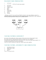
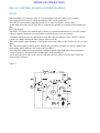
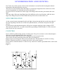
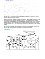
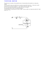
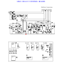
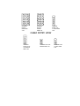
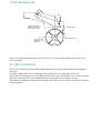
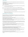
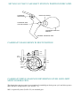
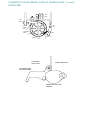
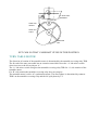
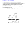
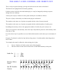
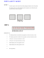
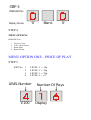
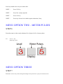
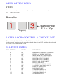
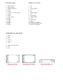
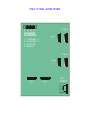
INSTALLATION MANUAL
Sound Leisure Limited
39 Ings Road. Leeds. LS9 9EJ
TELEPHONE
0113 2175000
(00 44 113 2175060)
INSTALLATION PROCEDURE
JUKE BOXES
Position Jukebox on level ground.
If there is no mains power within two metres, arrangements should be made for such a socket.
Once the jukebox is sited and various cables have been installed (see cable requirements) unbolt the
record play mechanism (The wing nuts are located underneath each corner of the mechanism).
Carry out a final check on all cable connections and turn machine on.
Check and, if necessary adjust price of play (see credit).
Set the pre-set gains on the amplifier to protect the speakers from overload at full volume.
Adjust treble and bass to suit.
Check all coins give correct amount of credit.
Program carousel with records.
WALLBOXES
Firmly affix the wall hanging so that the coin input slot is of a height that can be reached with ease.
The wall box, once hung on the bracket, is anchored with two raw bolts.
The holes in the wall box are oversized. This will assist in setting the wall box square if the bracket
is misaligned.
HIDEAWAY
The location of the hideaway is very important.
Most hideaway units are located in beer cellars.
If the beer cellar has a history of flooding or is hosed down, then it may require raising via a
platform and protecting.
CABLE REQUIREMENTS
1.
WALLBOX
A nine-core cable is required.
Incorporating three heavy-duty conductors for power and ground, and six conductors of a lighter
gauge for data.
SPECIFICATION
3 core
6 core
2.
Up To 50 metres
1.0mm2
0.22mm2
Over 50 metres
0.5 mm2
0.5mm2
VOLUME CONTROL AND REJECT
Four core cables of conductor size 0.22mm2 to 0.5 mm2
3.
SPEAKERS
Two core cable with index marking of size 0.5 mm2 to 0.75 mm2
CABLE CONNECTIONS
WALLBOX
A ten- way connector will be found in the Wall box on the small adapter board just below the main
computer circuit board.
An identical connector will be found in the main unit (Juke box / Hideaway).
Both of the connectors are marked 1 through 10 and connection is: 1 to 1, 2 to 2 and so on. Use the
heavy core cable on terminals 1, 2 & 10. Terminals 1 & 2 = Power and 10 = Ground.
There is a cable entry in the top and bottom of the Wall boxes and at the rear of all Juke Boxes and
Hideaways.
WARNING!
Using a cable of a smaller diameter on Terminals 1, 2 & 10 will cause intermittent or permanent
malfunction of the Wall box until the cable is replaced with cable of the correct type.
N.B
Each Wall box must have one intact single length of 9-core cable running full length back to the
main machine. SEE FIGURE 1.
WALLBOX CABLE DESIGNATION
1.
14 Volt AC
2.
3.
4.
5.
6.
7.
8.
9.
10.
14 Volt AC
Not used*
Collector Hold
SYNC
Pulse
B-side Trip
A-side Trip
SCAN
Ground
28 Volt AC centre tap to ground
*Although terminal 3 is not used for any Wall box function, at the main Machine terminal 3 is
grounded in the play mode and may be used in conjunction with switching kits for other equipment.
You may connect up to three wall boxes on a standard machine.
VOLUME CONTROLS AND REJECT
On receipt of the machine the volume controls will be connected on a short length of cable.
The volume control is initially housed inside the machine next to the amplifier.
The back of the volume control can be removed to reveal a four way terminal block marked 1 to 4.
An identical terminal block is fitted to the amplifier.
A four-core cable is required to connect the volume control to the amplifier.
VOLUME CONTROL AND REJECT CABLE DESIGNATION
1.
2.
3.
4.
Left channel volume
Right cannel volume
Common*
Reject
*This is not a permanent ground
SPEAKERS
Depending on which model machine you are installing, speaker connections are either by means of
plug and socket at rear of the machine, or a speaker matching board inside the cabinet.
In both situations + and – are marked.
All speaker cables should be run back to the main juke box (minimum impedance 4ohms per
channel).
POWER SUPPLY
MAINS INPUT
Factory set at 230volts unless otherwise requested.
A two metre length of three-core mains cable delivers main to two transformers via an on/off
switch.
The fuses are located on the mains input box, which also houses the on/off switch.
The transformers are housed at the base of the cabinet
One transformer supplies 28volts in a 14v-0-14v format
This voltage is supplied to the relay board through fuses f2, f3 and rated at 10 Amps.
It also acts as the ac supply for the main mpu board.
The second transformer has a dual function given its two outputs, 24v ac and 20v-0-20v.
The 24volt output is rectified on the relay board by BR1 and smoothed by C4 and protected by a
3.15amp fuse F1, now at 30volt dc this is used by the relay board for relay switching and scan
motor control/drive.
The 20v-0-20v is fused by F4 and F5 on the relay board and is used to supply the 40vac turntable
motor, also 20v-0-20v is rectified by BR2 and taken to plug ‘B’ for the amplifier.
MODE OF OPERATION
RELAY CONTROL BOARD AND MECHANISM
SCAN
When terminal 9 of connector strip ‘E’ is grounded this will cause diode D1 to conduct
Via resistor R4. The base of voltage at transistor TR1 will be pulled low.
TR1 (BC327) will conduct applying 30volts to one side of relay RL1 (Scan relay).
As the other end of the coil of relay RL1 is connected to ground via normally closed contacts on
MS1,
RL1 will energise.
When RL1 is energised its contacts apply 30volt via a protection thermistor to a tip3055 emitter
follower regulator transistor mounted on the metal back plate of the relay board.
A 560ohm pull up resistor is connected between the collector and base of the TIP3055 with an
18volt zener diode holding the base voltage stable at 18volt.
The emitter applies approximately 17volt to the scan motor (SM) via the contacts of trip ’A’ relay
(RL3).
The scan motor applies rotation power through the gear block assembly and spring clutch to the
white pulley wheel affixed to the front of the gear block.
The scan motor and gear block assembly is mounted on the right hand side of the mechanism.
A tension pulley is mounted on the left hand side of the mechanism.
A belt skirts the outer edge of the carousel and rides the two pulleys, friction drive rotates the
carousel anti clockwise.
Figure 2
SYNCHRONISATION AND COUNTING
Just To the rear of the operate switch on the mechanism is a metal bracket housing the infrared
transmitters and phototransistor receivers.
These devices are mounted astride the flange of a metal opto ring fixed to the centre boss of the
carousel (transmitter one side and receivers on the other).
One pair of devices monitor the inside edge of the flange while the other pair monitor the outer
edge.
The outer edge of the opto ring flange has a hole drilled at each record location, while the inner
edge of the flange has just one hole drilled directly below the record location 100.
SYNCHRONISATION
As the carousel rotates momentarily infra red light is shone through the hole on the inner edge of
the opto ring flange onto the face of the lower phototransistor, as location 100 passes the opto
devices.
For this short period the phototransistor will go low resistance applying a base voltage to TR7.
This will cause diode D11 to conduct momentarily grounding terminal number 5 of the connector
block E (the ten way connector).
COUNTING
Just as with the synchronising opto the counting opto will go low resistance as the infrared light is
allowed to pass through the holes of the opto ring.
The result of this is that TR4 (BC337) is turned on at each record location.
This in turn will allow transistors TR% and TR6 to be turned off.
Between each record location TR4 is turned off therefore TR5 and TR6 are turned on causing
LED1 to illuminate and D10 to conduct just before each record location.
D10 is taken to terminal number 6 of the ten-way connector E which is grounded before each record
location.
Figure 3
‘A‘ SIDE TRIP
Once the computer has counted to the record location required it will instruct the mechanism to
transfer the relevant record to the play position.
This instruction is called the trip instruction and is carried out as follows.
The carousel is turning and the computer applies a ground to terminal number 8 of the 10 way
connector causing D2 to conduct grounding R7 (18K resistor).
The carousel will continue to turn until the opto counting device sees the next record location. At
this point TR8 is turned on, this turns off TR11 allowing R7 to turn on TR2.
TR2 energises the trip ‘A’ relay (RL3), one set of contacts takes TR11 out of circuit while another
set of contacts reverse the polarity of the scan motor (SM).
The Detent latching coil is connected in series with D9 across the scan motor.
As the polarity is reversed the coil is instantly energised, pushing a latch against teeth on the rear of
the centre boss of the carousel. The carousel will run backwards to the previous record location
where the latch becomes firmly engaged.
At this point the spring clutch driving the belt pulley will slip. There is another spring clutch on the
gear block, which via a small gear will rotate the camshaft. The various lobes on the camshaft
operate the lift arm and clamp arm. A roller underneath the tone arm assembly follows the contours
of the left side of the central cam. When the play position is achieved MS3 is operated turning on
T10 which keeps the trip ‘A’ relay energised as the instruction from the computer is only of a short
duration.
MS1 is operated causing the scan relay to drop out and removing power from the scan motor. At
this point MS1 applies a ground to the volume control circuit lifting the mute.
Trip Circuit
Figure 4
Wall box Connections
1 2 3 4 5
6 7 8 9 10
‘B’ SIDE TRIP
Just as with the ‘A’ side trip, the computer will issue a trip instruction.
For ‘B’ side the trip instruction is given by grounding terminal number 7 of connector ‘E’, (the 10
way connector).
This will cause diodes D8 and D3 to conduct. D3 will turn on TR3, which in turn will energise RL3
trip ‘B’ relay.
The contacts of RL3 will energise the ‘B’ side solenoid (BSS ).
This is a coil mounted to the left of the tone-arm assembly.
Energising this coil will cause its armature to push the tone-arm guide roller to the right through a
cutaway in the camshaft, which is uppermost in the standby position.
The roller which for ‘A’ sides is normally offset to the left of the cam is now offset to the right.
Simultaneously D8 being connected to the same point as D2 will instigate an ‘A’ side trip, but this
time as the camshaft rotates the tone arm assembly will follow the right hand contour of the central
lobe of the camshaft, selecting the ‘B’ side of the record.
TURNTABL MOTOR
The direction of rotation of the turntable motor is determined by the turntable-reversing relay
(TRR).
The far end of the tone arm cradle has an extension arm which closes the ‘A’ side micro switch
when it moves to the left to play an ‘A’ side rotation of the turn table motor.
For ‘B’ side rotation the turntable-reversing relay does not energise.
The turntable motor is a 40v ac synchronous motor.
The direct phase is determined by contacts TRR1 on the turn table reversing relay and the 90° split
phase by C”, C3.
MK11 RELAY CONTROL BOARD
Wall box Connections
RELAY
RELAY
RELAY
A
RELAY
POWER
SUPPLY
PLUG
2 POLE
4 POLE
2 POLE
2 POLE
F1
F2 F3 F4 F5
AMPLIFIER
PLUG
B
C
D
E
1 2 3 4 5 6 7 8 9 10
1 2 3 4 5 6 7 8 9 10
PLUG A
PLUG B
PLUG C
1 20V A.C.
2
3 20V A.C.
4 12V A.C.
5
6 0V
7 12V A.C.
8
9 24V A.C.
10
11
12 24V A.C.
1 MUTE (A2)
2
3
4 REJECT (A4)
5
6
7 0V (A13)
8
9
10 –20V (A5)
11 +20V (A1)
12
1 M16
2 MUTE (M17)
3 REJECT (M2)
4
5 M5
6 M12 (10OHM 10W)
7
8
9 0V (M1)
10
11
12 M10
13 M13
14 M11
15 M19
PLUG D
PLUG E
1 M91
2
3
4 T/TABLE
5 M8
6
7 M,4
8 T/TABLE REV. (M15)
9
10 PULSE IN (M6)
11
12
13 M18
14 (M7) SYNC IN
15 M3
1 W/B 8
2 W/9
3
4 W/B3
5 SYNC (W.B.7)
6 PULSE OUT (W/B6)
7 ‘B’ SIDE TRIP (W/B5)
8 ‘A’ SIDE TRIP (W/B4)
9 SCAN IN (W/B2)
10 0V (W/B1)
SERVICE INFORMATION
PLEASE NOTE:
There are three different types of control units (Relay Boards) used on the Sound Leisure systems.
These are known as MK1, MK2 and hybrid, they are not directly interchangeable.
The MK1 is fitted to the earlier systems where the turntable is belt driven.
The MK1 can be identified by R1 which is a 47 ohms, and capacitor combination C2-C3 which will
be either 1 x 10uf or two 4.7uf.
The second relay board, part number ACS003 iss2 is a hybrid and could be used with a MK1 or
MK2 mechanisms providing the correct resistor R1 and capacitor combination C2-C3 are fitted.
The MK2 is fitted to later systems where the turntable is direct drive (Motor pulley driving directly
on to tyre on turn table).
The part number of this relay board is ACS1002 iss3. Resistor R1 will be 56 ohms and a 4.7uf
capacitor will be fitted in position C2 or C2 not both.
+ 30v
C5
GREEN
GA1
Y E L LO W
GA2
GREY
GA3
G3
P IN K
GA4
G4
G1
1K
D7
100K
100K
PULSE
D10
COUNT
D14
RESET
BUTTO N
MEMORY
HOLD
CIRCUIT
TR1
BASE
+30DC
ROTARY
CONTROL
SWITCH
BLACK
'A' SIDE
M/SW
D5
VIOLET
RELAY
D.C.
'B' side shift solenoid
WHITE
D1
TRIP 'B'
SCAN OFF PLAY
RED
C15
T.T
REV
O PTO
U N IT
B LU E
D13
SCAN
G2
M/SW3
TR2
BASE
D15
BROWN
TRIP
BUTTON
BLUE
REED SWITCH
n
sca lay
e
r
+30DC
C3
AMP
MUTING
C2
40V
A.C.
C1
D8
DC
RELAY
0V A.C.
8UF
50V
D4
GREEN
1
1
M/SW1
YELLOW
1
47R
1
GREY
M/SW2
0.22UF
F1
1
PINK
1
1
BLUE
1
1
FA3
FA2
F2
T/T
MOTOR
F3
RED
C6
TRIP 'A'
RELAY
1
C9
1
BLACK
1
16VO LT
SC AN
M OTO R
1
C13
IN4004
0.1UF
LATCH
SO LENO ID
VIO LET
TRIP 'A'
RELAY
1
1
CHASSIS
EARTH
30V
30V
C12
C13
1
2
3
3
2
1
4
5
6
6
5
4
7
8
9
9
8
7
1
2
10 11 12
12 11 10
3
13 14 15
15 14 13
4
HARNESS
PLUG 'C'
MALE PINS
2.36
HARNESS
PLUG 'D'
FEMALE
PINS 3.36
HARNESS
PLUGS 'F' &
'G' MALE PINS
1.58
CABLE ENTRY VIEW
1
2
3
1
1
4
2
2
HARNESS
PLUGS 'Fa' &
'Ga' FEMALE
PINS 1.58
HARNESS PLUG 'HA'
FEMALE PINS 1.58
HARNESS PLUG
'H' MALE PINS
1.58
TONEARM RELEASE
PIVOT
TONE ARM
TONE ARM RELEASE
VIEWED FROM RIGHT
HAND SIDE OF MECH
TONE ARM CAM
VIEWED IN PLAY
POSITION
RELEASE LEVER
RIB AROUND CAM
There is no adjustment to the tone arm release lever, except to ensure that the cam stops in the
correct position.
‘B’ SHIFT SOLENOID
The ‘B’ shift solenoid is mounted through slotted holes allowing a small amount of adjustment
sideways.
To adjust, slacken off the two mounting screws and push the coil body fully to the left.
Then push in the plunger core to the right so that it moves the cam follower to its extreme position
and at the same time forces the solenoid body to this position, now re-tighten screws.
This method of adjustment ensures that when the cam roller is at its extreme of travel the solenoid
is fully engaged.
TRANSFER
As soon as the scan motor reverse, the drive changes from the carousel to the camshaft via nonreversing clutches.
As the camshaft revolves, moving the record and tone arm into position, it operates three micro
switches situated on the gear block housing.
These are numbered MS1-3
MS1- Closes as soon as the camshaft starts to rotate to ensure that the trip ‘A’ side relay remains
energised throughout the transfer cycle.
MS-2 Closes as soon as the camshaft starts to rotate to power the turntable motor TM.
MS-3 When the camshaft reaches the record play position (half turn from rest), MS1 breaks the
ground feed from the scan relay and grounds the amplifier muting circuit to provide audio.
The scan relay SR de-energises and the scan motor stops.
When either the reject button or the reject reed switch closes the scan relay energises and the
camshaft rotates to reject the record.
MICROSWITCH ADJUSTMENT
Micro switches numbered 1,2 and 3areare operated by cam profiles on main camshaft drive gear
and detent lever on gear block (see fig 6). Profile ‘A’ and the detent lever operate micro switches 2
and 3. Profile ‘B’ operates micro switch 1.
Only minor adjustments are needed to the micro switches.
Make sure that micro switches 2 and 3 are fully closed by the detent lever in the record transfer
cycle and fully opened in the scan position.
Micro switch 1 can be adjusted by slackening the holding nut M5 on the gear block, and moving the
complete switch assembly to the required position.
The setting of MS1 determines the stop position of the main camshaft when it plays a record. Note
the cam, which operates the record transfer arm. Cam 1 should be set so that the transfer arm roller
is in the middle of the small lobe of the cam when its stops.
Micro switch 3 determines the stop position of the main camshaft. After operation the carousel
either rotates or remains stationary to await the next selection.
To adjust the stopping position of the camshaft the following note should be read in conjunction
with fig 7.
Loosen nut M5 on the eccentric stud located on the top of the gear block assembly.
The assembly can then be adjusted by the use of a small screwdriver.
Adjust the assembly so that micro switch 3 and 2 opens when the cam operating the transfer arm
has maximum clearance from the record magazine when the camshaft stops.
A check should be made to see that the cam operating the tone arm has stopped, with the roller
operated by the ‘B’ side shift solenoid BSS resting in the gap in the cam (fig 7).
Micro switch 2 should operate to stop the turntable motor.
When all checks have been made tighten the nut M5 whilst retaining the eccentric stud in the set
position.
SET MS1 SO THAT CAM SHAFT STOPS IN POSITION INDICATED
TRANSFER
ARM PIVOT
MAIN CAM SHAFT
TRANSFER ARM
CAM FOLLOWER
TRANSFER ARM CAM
PROFILE
RECORD TRANSFER ARM
CAMSHAFT GEAR SHOWN IN REST POSITION
MS2
MS3
TRIP
BUTTON
'A'
DETENT
LEVER
ARM
M5
NUT
'B'
CAMSHAFT
GEAR
C
NO
MS1
NC
CAMSHAFT DRIVE GEAR NON REVERSING LEVER AND LIMIT
SWITCH OPERATION
The detent lever arm prevents reverse rotation of camshaft gear during scan cycle and also operates
MS2 and MS3 during transfer cycle (Profile ‘A’).
MS1 is operated by boss (Profile ‘B’) on camshaft gear.
CAMSHAFT GEAR SHOWN IN PLAY POSITION MS 1, 2, and 3
OPERATED
MS2
MS3
TRIP
BUTTON
M5
NUT
DETENT
LEVER
ARM
CAMSHAFT
GEAR
MS1
Profile 'A'
TRANSFER
ARM PIVOT
Profile 'B'
MAIN CAM SHAFT
TRANSFER ARM
CAM FOLLOWER
TRANSFER ARM CAM
PROFILE
'B' SIDE SHIFT
SOLENOID
ROLLER
TONE ARM
CRADLE
MAIN CAM
SHAFT
TONE ARM
CAM
SET CAM SO THAT CAMSHAFT STOPS IN THIS POSITION
TURN TABLE MOTOR
The direction of rotation of the turntable motor is determined by the turntable-reversing relay TRR.
The far end of the tone arm cradle has an extension arm which closes the ‘A’ side micro switch
when it moves to the left to play an ‘A’.
The ‘A’ side micro switch energises the turntable-reversing relay TRR for ‘A’ side rotation of the
turntable motor.
For ‘B’ side rotation the turntable-reversing relay does not energise.
The turntable motor is a 40v AC synchronous motor. The direct phase is determined by contacts
TRR1 on the turntable-reversing relay and the 90º split phase by C2.
SETTING UP THE OPTO UNIT
The output from the opto unit must correspond correctly with the carousel position.
To ascertain this, observe the action of the carousel latch arm ratchet.
The pulse L.E.D. should extinguish about haft way along the tooth of the ratchet and energise just
before the edge of the tooth.
Adjust this position with the screws on the opto unit mounting. The top hole is slotted.
When this is correct, reverse the carousel so that it is pushing against the ratchet tooth and ensure
the pulse L.E.D. does not extinguish.
The output from the opto unit pulse line can be measured at the junction of R24, R25 (TP2) and the
sync line at the junction of R28, R27 (TP3).
The action is such that when the infra red light beam is allowed to pass through the hole in the opto
disc the voltage at TP2 and TP3 should be at least 25V.
CAROUSEL LATCH
SOLENOID
CAROUSEL LATCH
ARM
SCAN
CAROUSEL RATCHET TEETH
OPTO RING
RECORD 100
101
COUNTING PULSES
102
103
THE EARLY 4 COIN CONTROL AND CREDIT UNIT
This is easily recognised, having a pricing card socket across the centre of the board.
This board is not equipped with electronic popularity.
Facilities such as 140/200 select and random play etc. may be changed by ordering an eprom
change from our tech dept.
A basic price of play is written in to the eprom and may be overridden as follows.
The price of play is selected by wire links on the plug in credit board.
The number on the inner row of points correspond with the value of money inserted.
The number on the outer row of points correspond with the with the number of credits given.
By linking the monetary value to the appropriate number of credits, the price of play is set.
There is one point for each monetary value from 10p to 50p and two points for each monetary value
from 60p to 100p.
For value above 60p it is possible to use two links which sum the credit values up to a maximum of
19.
Example: To obtain 14 credits for 90p, link one 90p point to 10 credits and the other 90p point to
the 4 credits.
Two simple rules must be adhered to when setting price of play:
a.
b.
No two ‘Number of Credits’ points can be linked together.
Not more than one link can be connected to an individual monetary value point.
Links for 1 ---- 10p
7 ---- 50p
16 ---- 100p
Money Value
Point
No Of Credits
Points
10 20 30 40 50 60 60 70 70 80 80 90 100
1
2
3
4
5
6
7
8
9
10 90 100
Links for 1 ---- 10p
5 ---- 50p
12 ---- 100p
Money Value
Point
No Of Credits
Points
10 20 30 40 50 60 60 70 70 80 80 90 100
1
2
3
4
5
6
7
8
9
10 90 100
POPULARITY MODE
STEP 1
Turn the operate switch on the front of the playing mechanism to the off position.
The display will start to flash displaying the least played record followed by the
amount of times it has been played.
Display
STEP 2
1 2 3 4 5 6 7 8 9 0 R
KEYBOARD LAYOUT
PRESS KEY No
1
The display advances towards the most popular record one location at a time.
2
The display steps back towards the least popular record one location at a time.
3
As Key No. one only ten locations at a time.
4
As Key No. two only ten locations at a time.
5
Instant display of the most popular record.
6
Instant display of the least popular record.
7
8
Reset popularity.
STEP 3
PRESS KEY No
Display Shows
Blank
‘0’
‘0’
STEP 4
MENU OPTIONS
PRESS KEY No
1 Plays for Coins
2 Coins / Meter Pulses
3 Bonus Plays
4 Bonus Pricing
MENU OPTION ONE – PRICE OF PLAY
STEP 5
KEY No 1
2
3
4
LEVEL 1
LEVEL 2
LEVEL 3
LEVEL 4
LEVEL Number
£100
=
=
=
=
10p
20p
50p
£1
Number Of Plays
Display
Press key number for level you wish to alter
NEXT :-
Press ‘R’ Key
NEXT :-
Press No. of plays required.
NEXT :-
Press ‘R’ Key
NEXT :-
Press key for next level which requires alteration, if any.
MENU OPTION TWO – METER PULSES
STEP 6
Procedure same as above only substitute No. of plays for No. of meter pulses.
EG.
Level 3 – 50p
Requiring 5 pulses
Level
Meter Pulses
Display
MENU OPTION THREE
STEP 7
Procedure as above only central and right hand digits will represent No. of plays for each bonus level.
MENU OPTION FOUR
STEP 8
Procedure as above only central and right hand digits are the price that each bonus addition takes place.
EG.
1st Bonus Level at 30p
Bonus No
Display
Starting Price
IE 3 = 30p
LATER 4 COIN CONTROL & CREDIT UNIT
This control and credit unit is far more flexible in its operation than its predecessor.
A wide range of functions may be accessed or altered either via the D.I.L. switches, the keyboard,
or in some cases a combination of both.
D.I.L. SWITCH LISTING
D.I.L. SWITCH
8
8
7
7
6
6
5
5
4
4
3
3
2
1
1+2
1+2
STATE
FUNCTION
ON
OFF
ON
OFF
ON
OFF
ON
OFF
ON
OFF
ON
OFF
ON
ON
ON
OFF
PERMANENT FREE PLAY POSITION
FREE PLAY INHIBIT POSITION
MENU MODE ACCESS POSITION
MENU MODE INHIBIT POSITION
PRINTER OUTPUT ENABLE
PRINTER OUTPUT INHIBIT
PRINT CASH + POPULARITY
PRINT CASH ONLY
200 SELECT MACHINES ONLY
140 SELECT MACHINES ONLY
DISPLAY POPULARITY
POPULARITY OFF
15 MIN RANDOM PLAY
20 MIN RANDOM PLAY
30 MIN RANDOM PLAY
NO RANDOM PLAY
KEYBOARD
DISPLAY PLUG
1
2
3
4
5
6
7
8
9
10
11
12
13
14
15
1
2
3
4
5
6
7
8
9
10
11
12
13
14
15
Spare output
Spare output
Keyboard Strobe
K.B.7.
K.B.6.
17V D.C. meter/common
K.B.5.
K.B.3.
K.B. Cancel
K.B.2
K.B.0.
K.B.9.
K.B.4.
K.B.1
K.B.8.
0V
A2
Strobe $5000
A1
A0
Strobe $4800
A3
50p Switch
Strobe $4800
+5V
10p Switch
Meter
Test SW. common
Selection playing lamp
Select record lamp
TERMINAL BLOCK
1 Pulse.
2 Sync.
3 0.V
4
Trip ‘B’
5
6
7
8
9
10
Trip ‘A’
Scan
Memory hold switch
12V
12V
1
13
3
15
3
15
1
13
Display Plug
KeyBoard Plug
1
10
Terminal Block
MK2 VYNIL AMPLIFIER
TREBLE
1
1 2 3 4
VOLUME
CONTROL
1.
2.
3.
4.
BASS
1
CHANNEL 1
CHANNEL 2
GROUND
REJECT
TREBLE
2
BASS
2
GAIN
1
GAIN
2
P/U
INPUT
MK4 VYNIL AMPLIFIER
CH2
Ch1
TREBLE
2
TREBLE
1
1.
2.
3.
4.
1 2 3 4
CHANNEL 1
CHANNEL 2
GROUND
REJECT
MASTER VOLUME
MASTER VOLUME
BASS
2
BASS
1
AUX
VOLUME
CONTROL
MIC
BASS
MIC
VOLUME
CONTROL
JUKEBOX
INPUT
AUX
INPUT
MIC
INPUT
THE PICKUP CARTRIDGE
MECHANICAL SPECIFICATION
TYPE
PICKERING STEREO
Stylus force
Tracking capability
Weight
Stylus pull out force
4 Grams nominal
15cm/sec
8 grams nominal
8 to 40 ounces
ELECTRICAL SPECIFICATION
Resistance, d.c.
Inductance
Load resistance
Load capacitance
Output nominal
Channel separation
Frequency response
Channel balance
Shielding
530ohms nominal
390m, Henries nominal
10,000 ohms
260 Pico farads
1.25mV/cm sec ± 3dB @ 1Khz
16 dB min. @ 1Khz
15hz to 20Khz
2 dB max output difference
annealed mu metal case
STANDARD PRE AMPLIFIER
Number of inputs
Input specification
Input facility
one
( R.I.A.A.) EQ
mono
SIGNAL
The signal is taken through a mono first stage and is split into two mono channels, each with
individual treble, bass and pre set gain controls.
VOLUME
The independent control of each channel is possible via a twin slider volume control.
The volume control circuit is of the D.C. type and may be run over long distances without the use
of screened cable.
Output
2 times 2 volts max
MK4 PRE AMPLIFIER
Number of inputs
Three
Input 1
Mic input 1st priority input with automatic voice
activated auto fade. Pre set gain control independent
treble and bass controls.
Suitable for high or low impedance mic’s
Input 2
Juke box 2nd priority input (R.I.A.A.) EQ with
automatic signal activated auto fade. Mono input split
to two channels each with pre set gains, treble and bass
controls.
Input 3
B.G.M. auto fade in approximately 45 seconds after
last record played.
Pre set gain control. Input suitable for signal from line
level.
POWER AMPLIFIER
The power output stage is overload protected
Frequency range
Output impedance
Power Output
15 Hz to 100 Khz Flat response
4 ohms min.
60 Watts per channel R.M.S into 4 ohms.