1
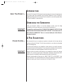
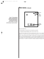
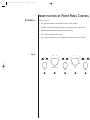
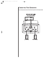
HPS500/1000 OM
10/25/99
2:40 PM
Page 1
HPS
High-Performance Subwoofers
Model HPS-500
Model HPS-1000
Owner’s Manual
®
HPS500/1000 OM
10/25/99
2:40 PM
Page 2
TABLE OF CONTENTS
Caution.....................................................................................................................................3
Important Safety Instructions....................................................................................................4
Introduction..............................................................................................................................5
About This Product..............................................................................................................5
Unpacking the Subwoofer.........................................................................................................5
A Few Suggestions ....................................................................................................................5
Volume Control ...................................................................................................................5
Positioning............................................................................................................................6–7
Identification of Front Panel Control ........................................................................................8
Controls...............................................................................................................................8
Connecting Your Subwoofer ...............................................................................................9–11
Operation ...............................................................................................................................12
Set Controls .......................................................................................................................12
Power On ..........................................................................................................................12
Adjust Gain........................................................................................................................12
Crossover Adjustments ......................................................................................................12
Phase Control ....................................................................................................................12
A Word of Advice ...................................................................................................................13
Overdrive Protection...............................................................................................................13
A Word About Tone Controls..................................................................................................13
Care of Your Subwoofer ..........................................................................................................14
Feedback ................................................................................................................................14
In Case of Trouble With Your Subwoofer................................................................................14
Specifications ..........................................................................................................................15
HPS500/1000 OM
10/25/99
2:40 PM
Page 3
CAUTION
RISK OF ELECTRIC SHOCK
DO NOT OPEN
WARNING: SHOCK HAZARD – DO NOT OPEN.
AVIS: RISQUE DE CHOC ELECTRIQUE – NE PAS OUVRIR.
CUIDADO: PELIGRO DE CHOQUE ELÉCTRICO – NO ABRIR.
CAUTION: TO REDUCE THE RISK OF ELECTRIC SHOCK
DO NOT REMOVE COVER (0R BACK)
NO USER SERVICEABLE PARTS INSIDE
REFER SERVICING TO QUALIFIED PERSONNEL
THIS INFINITY PRODUCT IS DESIGNED FOR 120-VOLT USE ONLY! FOR
DETAILED SAFETY PRECAUTIONS, PLEASE SEE FOLLOWING PAGE IN THIS
OWNER’S MANUAL FOR “IMPORTANT SAFETY INSTRUCTIONS.”
The lightning flash with arrowhead symbol, within an equilateral triangle,
intended to alert the user to the presence of uninsulated “dangerous voltage” with
in the product’s enclosure that may be of sufficient magnitude to constitute a risk o
electric shock to persons.
The exclamation point within an equilateral triangle is intended to alert the use
to the presence of important operating and maintenance (servicing) instructions i
the literature accompanying the product.
L’éclair avec le symbole de la flèche, placé dans les limites d’un triangel équilatéral e
prévu pour avertir l’utilisateur de la présence de “tension dangereuse” non isolée dan
l’enceinte du produit qui pourrait être d’une importance suffisante pour présenter u
risque d’électrocution aux personnes.
Le point d’exclamation dans un triangel équilateral est prévu pour avertir l’utilisateu
de la présence d’instructions importantes pour les opérations et l’entretien (service
dans les manuels fournis avec l’appareil.
ATTENTION: POUR EVITER LES CHOCS ELECTRIQUES, INTRODUIRE
LA LAME LA PLUS LARGE DE LA FICHE DANS LA BORNE
CORRESPONDANTE DE LA PRISE ET POUSSER JUSQUAU FOND.
Este destello luminoso con un símbolo de punta de flecha dentro de un triángulo equ
látero tiene el objectivo de alertar al usuario sobre la presencia de “voltaje peligroso” n
aislado dentro de la caja del producto que puede ser de magnitud lo suficientemen
grande para constituir un riesgo de choque eléctrico para las personas.
Este punto de exclamación dentro de un triángulo equilátero tiene el objectivo de ale
tar al usuario sobre la existencia de instrucciones operativas y de mantenimient
(servicio) importantes en la literatura que acomaña el aparato.
CUIDADO: PARA REDUCIR EL RIESGO DE CHOQUE ELÉCTRICO, NO
RETIRE LA CUBIERTA (O RESPALDO). DENTRO NO HAY PIEZAS A LAS
QUE EL USUARIO PUEDA DAR SERVICIO. REMITA EL SERVICIO AL
PERSONAL DE SERVICIO CALIFICADO.
HPS500/1000 OM
10/25/99
2:40 PM
Page 4
IMPORTANT SAFETY INSTRUCTIONS
1) Read Instructions – All the safety and operating
instructions should be read before the product is operated.
2) Retain Instructions – The safety and operating
instructions should be retained for future reference.
3) Heed Warnings – All warnings on the product and
in the operating instructions should be adhered to.
4) Follow Instructions – All operating and use instructions should be followed.
5) Cleaning – Unplug this product from the wall outlet before cleaning. Do not use liquid cleaners or
aerosol cleaners. Use a damp cloth for cleaning.
Exception: A product that is meant for uninterrupted
service and that for some specific reason, such as the
possibility of the loss of an authorization code for a
CATV Converter, is not intended to be unplugged by
the user for cleaning or any other purpose, may exclude
the reference to unplugging the product in the cleaning
description otherwise required in number 5.
6) Attachments – Do not use attachments not recommended by the product manufacturer as they may
cause hazards.
7) Water and Moisture – Do not use this product near
water – for example, near a bathtub, washbowl, kitchen
sink, or laundry tub; in a wet basement;
or near a swimming pool; and the like.
8) Accessories – Do not place this product on an
unstable cart, stand, tripod, bracket,
or table. The product may fall,
causing serious injury to a
child or adult, and serious
damage to the product. Use
only with a cart, stand, tripod, bracket, or table recommended by the manufacturer,
or sold with the product. Any
mounting of the product should
follow the manufacturer’s instructions, and should use
a mounting accessory recommended by the manufacturer.
9) A Product and Cart Combination Should Be
Moved With Care – Quick stop, excessive force, and
uneven surfaces may cause the product and cart combination to overturn.
10) Ventilation – Slots and openings in the cabinet are
provided for ventilation and to ensure reliable operation of the product and to protect it from overheating,
and these openings must not be blocked or covered.
The openings should never be blocked by placing the
product on a bed, sofa, rug, or other similar surface.
This product should not be placed in a built-in installation such as a bookcase or rack unless proper ventilation is provided or the manufacturer’s instructions have
been adhered to.
11) Power Sources – This product should be operated
only from the type of power source indicated on the
marking label. If you are not sure of the type of power
supply to your home, consult your product dealer or
local power company. For products intended to operate
from battery power, or other sources, refer to the operating instructions.
12) Grounding or Polarization –
This product may be equipped
with a polarized alternating-current-line plug (a plug having one
blade wider than the other). This
plug will fit into the power outlet
only one way. This is a safety feature. If you are unable to insert
the plug fully into the outlet, try
reversing the plug. If the plug
should still fail to fit, contact your
electrician to replace your obsolete outlet. Do not defeat the
safety purpose of the polarized
plug.
Figure A.
ANTENNA
LEAD-IN
WIRE
GROUND
CLAMP
ANTENNA
DISCHARGE UNIT
(NEC SECTION 810-21)
ELECTRIC
SERVICE
EQUIPMENT
13) Power-Cord Protection –
Power-supply cords should be
routed so that they are not likely
to be walked on or pinched by items placed upon or
against them, paying particular attention to cords at
plugs, convenience receptacles, and the point where
they exit from the product.
14) Outdoor Antenna Grounding – If an outside
antenna or cable system is connected to the product, be
sure the antenna or cable system is grounded so as to
provide some protection against voltage surges and
built-up static charges. Article 810 of the National
Electrical Code, ANSI/NFPA 70, provides information
with regard to proper grounding of the mast and supporting structure, grounding of the lead-in wire to an
antenna discharge unit, size for grounding conductors,
location of antenna-discharge unit, connection to
grounding electrodes, and requirements for the
grounding electrode. See Figure A.
15) Lightning – For added protection for this product
during a lightning storm, or when it is left unattended
and unused for long periods of time, unplug it from
the wall outlet and disconnect the antenna or cable system. This will prevent damage to the product due to
lightning and power-line surges.
16) Power Lines – An outside antenna system should
not be located in the vicinity of overhead power lines
or other electric light or power circuits, or where it can
fall into such power lines or circuits. When installing
an outside antenna system, extreme care should be
taken to keep from touching such power lines or circuits as contact with them might be fatal.
17) Overloading – Do not overload wall outlets, extension cords, or integral convenience receptacles as this
can result in a risk of fire or electric shock.
18) Object and Liquid Entry – Never push objects of
any kind into this product through openings as they
may touch dangerous voltage points or short out parts
that could result in a fire or electric shock. Never spill
liquid of any kind on the product.
19) Servicing – Do not attempt to service this product
yourself as opening or removing covers may expose you
to dangerous voltage or other hazards. Refer all servicing to qualified service personnel.
GROUNDING CONDUCTO
(NEC SECTION 810-21)
GROUND CLAMPS
POWER SERVICE GROUNDING
ELECTRODE SYSTEM
(NEC SECTION 810-21)
20) Damage Requiring Service – Unplug this produ
from the wall outlet and refer servicing to qualified se
vice personnel under the following conditions:
a) When the power-supply cord or plug is damaged.
b) If liquid has been spilled, or objects have fallen int
the product.
c) If the product has been exposed to rain or water.
d) If the product does not operate normally by follow
ing the operating instructions. Adjust only those con
trols that are covered by the operating instructions
an improper adjustment of other controls may result i
damage and will often require extensive work by a qua
ified technician to restore the product to its norm
operation.
e) If the product has been dropped or damaged in an
way.
f) When the product exhibits a distinct change in pe
formance – this indicates a need for service.
21) Replacement Parts – When replacement parts a
required, be sure the service technician has use
replacement parts specified by the manufacturer or th
have the same characteristics as the original par
Unauthorized substitutions may result in fire, electr
shock, or other hazards.
22) Safety Check – Upon completion of any service o
repairs to this product, ask the service technician t
perform safety checks to determine that the product
in proper operating condition.
23) Wall or Ceiling Mounting – The product shou
be mounted to a wall or ceiling only as recommende
by the manufacturer.
24) Heat – The product should be situated away from
heat sources such as radiators, heat registers, stoves, o
other products (including amplifiers) that produc
heat.
HPS500/1000 OM
10/25/99
2:40 PM
Page 5
INTRODUCTION
ABOUT THIS PRODUCT...
Infinity’s HPS-500 and HPS-1000 subwoofers have been designed to enhance the bass frequencie
of any audio system. Both subwoofers may be used with speakers of any size. Obviously, th
greatest bass enhancement will be achieved when the subwoofer is connected to speakers that d
not have the capability to create deep bass.
UNPACKING THE SUBWOOFER
Check your subwoofer carefully. If it has been damaged in transit, report the damag
immediately by calling your dealer and/or the trucking firm that delivered it.
IMPORTANT!
To prevent fire or shock hazard, DO NOT EXPOSE THIS SUBWOOFER SYSTEM TO RAIN
EXCESSIVE MOISTURE OR PROLONGED DIRECT SUNLIGHT. To avoid electric shock, D
NOT OPEN THE SUBWOOFER! There are no user-serviceable parts inside. Observe a
warnings and cautions.
A FEW SUGGESTIONS
VOLUME CONTROL...
We recommend that you not operate your speakers or subwoofer with the bass, treble an
loudness controls set to full boost. This will place undue strain on your electronics and speaker
and could damage them.
The volume control setting on your preamplifier or stereo receiver is not a specific indication o
the overall loudness level of the speakers. The only important consideration is the loudness lev
at which the system can be played regardless of where the volume control is set.
IMPORTANT!
Always turn down the volume control setting on your preamplifier or stereo when changing
cassette or CD, or switching inputs to AM or FM operation. Excessively loud transients (clicks o
popping sounds) can damage the satellite speakers and possibly the subwoofer.
Whenever changing cables, pulling plugs, etc., ALWAYS TURN OFF ALL EQUIPMENT, includ
ing the subwoofer. This prevents transients from entering the speakers and prevents electric
energy from reaching you. Keep all connections out of the reach of children.
HPS500/1000 OM
10/25/99
2:40 PM
Page 6
POSITIONING
POSITION WITHIN
A ROOM WILL
STRONGLY INFLUENCE
PERFORMANCE...
Since the installation of a subwoofer can be somewhat more complicated than installin
full-range speakers, it is essential that you read this section very carefully prior to connecting th
subwoofer to your system. Should you have questions relating to your installation, it is advisabl
to call either your dealer or Infinity’s Customer Service Department for advice.
The performance of the subwoofer is directly related to its placement in the listening room an
how you align the subwoofer with its satellite speakers. Setting the volume of the subwoofer i
relationship to the left and right speakers is also of critical importance because it is essential tha
the subwoofer integrates smoothly with the entire system. Setting the subwoofer’s volume leve
too high will result in an overpowering, boomy bass. Setting the volume level too low will negat
the effect of the subwoofer.
We recommend placing the subwoofer at least 2 to 3 feet away from a television or a computer
disc-drive system to prevent smearing the colors of the TV picture or erasing of the magnet
drive.
Here are several additional facts on installation that may prove useful. It is generally believed b
most audio authorities that low frequencies (below 125Hz) are nondirectional and, therefore
placement of a subwoofer within any listening room is not critical. While in theory it is true tha
the larger wavelengths, of extremely low frequencies, are basically nondirectional, the fact is tha
when installing a subwoofer within the limited confines of a room, reflections, standing wave
and absorptions generated within the room will strongly influence the performance of an
subwoofer system. As a result, specific location of the subwoofer becomes important, and w
strongly recommend that you experiment with placement before choosing a final location.
Placement will depend upon your room and the amount and quality of bass required (fo
example, whether or not your room permits placement of the subwoofer near either satellite
The HPS-500 utilizes a downfiring woofer with a hyperflared port at the rear of the enclosure
Be sure to leave a minimum of six inches between the wall and the port on the HPS-500, or si
inches between the wall and the passive radiators on the HPS-1000.
HPS500/1000 OM
10/25/99
2:40 PM
Page 7
POSITIONING (Continued)
HPS SUB
RIGHTCHANNEL
SPEAKER
Figure 1. This view shows the
subwoofer positioned behind the
right-channel satellite speaker to
re-create the actual location of
bass instruments in an orchestra
and/or add impact to movie sound tracks.
PRIMARY
LISTENING
AREA
Here are some useful hints:
1. Experimentation with the position of your subwoofer may be useful.
2. If bass response seems inadequate, move it closer to a wall or corner.
It may take time and patience to find the most pleasing acoustic location for your subwoofe
Testing for sonic balance and blending should always be made from your normal listenin
position, using a wide range of source material. As a starting point, initially place the subwoofe
behind your right-channel satellite speaker, six inches from the wall. We suggest trying this loca
tion first because, in an orchestra, the bass instruments are usually located in the back and to th
right (see Figure 1). This position will also allow for emphatic, deep bass while playing movies
HPS500/1000 OM
10/25/99
2:40 PM
Page 8
IDENTIFICATION OF FRONT PANEL CONTROL
CONTROLS...
(Refer to Figure 2.)
1. EQ: Optimizes subwoofer performance for audio or video playback.
2. Crossover: Controls the frequency below which the subwoofer will begin working.
3. Phase: Reverse/normal switch changes audio-signal polarity.
4. Gain: Controls subwoofer volume level.
5. Input: Switches between the normal line/speaker inputs and the direct-LFE input.
Figure 2.
150
AUDIO
50
10
0˚
VIDEO
180˚
100
CROSSOVER
EQ
1
0
NORMAL
GAIN
PHASE
2
DIRECT
3
INPUT
4
5
HPS500/1000 OM
10/25/99
2:40 PM
Page 9
CONNECTING YOUR SUBWOOFER
If your receiver/processor does not have subwoofer outputs for the left and right channel
L
+
R
—
—
INPUTS
+
+
B-LINK™
L
+
—
OUTPUTS
R
—
HPS500/1000 OM
10/25/99
2:40 PM
Page 10
CONNECTING YOUR SUBWOOFER (Continued)
NOTE: Some receivers have a single
subwoofer output (do not confuse this
with a single LFE output as described
below). In that case, it is recommended
that you use a Y connector (not included)
to maximize performance.
If your receiver/processor has subwoofer outputs for the left and right channels:
LOW
LEVEL
IN
LOW
LEVEL
OUT
L
HIGHPASS
OUTPUT
120Hz
160Hz
80Hz
NOTE: In this case, you do not need to
use a Y connector. Simply connect the
LFE output on your receiver/processor
to either the left or right input on
the subwoofer.
R
If you have a Dolby* Digital or DTS® receiver/processor with a low-frequency-effect
(LFE) output:
SUBWOOFER OR
LFE OUTPUT
LOW
LEVEL
OUT
LOW
LEVEL
IN
L
HIGHPASS
OUTPUT
120Hz
160Hz
80Hz
R
HPS500/1000 OM
10/25/99
2:40 PM
Page 11
If your receiver/amplifier has preamp output jacks and main input jacks for the left an
right channels or you have a separate preamp/processor and power amplifier:
This method of hookup can offer the highest level of performance for your complete loudspeak
system. Your subwoofer incorporates an adjustable high-pass crossover in addition to a variab
low-pass crossover. When hooked up as shown below, the subwoofer will limit the low-frequenc
information that is returned to your receiver/amplifier. Your receiver/amplifier does not need t
waste valuable power reproducing the low frequencies. In addition, since no low-frequenc
information is being sent to your main loudspeakers, they are able to reproduce mid and hig
frequencies with greater clarity.
LOW
LEVEL
OUT
HIGHPASS
OUTPUT
120Hz
160Hz
80Hz
LOW
LEVEL
IN
L
R
RECEIVER/AMPLIFIER
OR PROCESSOR/AMPLIFIER
PRE
OUT
MAIN
IN
LEFT
RIGHT
LOUDSPEAKER
RIGHT
MAIN SPEAKER
OUTPUT
RIGHT
LEFT
LEFT
LOUDSPEAKER
HPS500/1000 OM
10/25/99
2:40 PM
Page 12
OPERATION
SET CONTROLS...
1.
Initially set the HPS’s Gain control to the “O” position.
2.
Initially set the HPS’s Crossover control to the 100Hz position.
3.
Plug your HPS’s AC cord into a wall outlet. Do not use the outlets on the back of the receive
4.
Turn on your HPS sub by pressing the power button on the center of the front panel.
5.
Turn on your entire audio system and start a CD or movie sound track at a moderate leve
6.
Turn your HPS’s Gain control 4 (Figure 2) up to the “5” position (half way). If no soun
emanates from the subwoofer, check the AC-line cord and input cables. Are the connector
on the cables making proper contact? Is the AC plug connected to a “live” receptacle? Ha
the power button been pressed to the “on” position? (Note: A green indicator on the fron
panel will light when the power is on.) Once you have confirmed that the subwoofer
active, proceed by playing a CD, record or cassette. Use a selection that has ample bas
information.
7.
Set the overall volume control of the preamplifier or stereo to a comfortable level. Adju
the subwoofer’s Gain control 4 (Figure 2) until you obtain a pleasing blend of bass. Bas
response should not overpower the room but rather be adjusted so there is a harmoniou
blend across the entire musical range. Many users have a tendency to set the subwoofe
volume too loud, adhering to the belief that a subwoofer is there to produce lots of bas
This is not entirely true. A subwoofer is there to enhance bass, extending the response o
the entire system so the bass can be felt as well as heard. However, overall balance mu
be maintained or the music will not sound natural. An experienced listener will set th
volume of the subwoofer so its impact on bass response is always there but never obtrusiv
CROSSOVER ADJUSTMENTS…
8.
Crossover Control 2 (Figure 2) – The Low-Pass control determines the highest frequenc
at which the subwoofer reproduces sounds. If your main speakers can comfortably reproduc
some low-frequency sounds, set this control to a lower frequency setting, betwee
50Hz – 100Hz. This will concentrate the subwoofer’s efforts on the ultradeep bass sound
required by today’s films and music. If you are using smaller bookshelf speakers that d
not extend to the lower bass frequencies, set the low-pass crossover control to a highe
setting, between 120Hz – 150Hz.
PHASE CONTROL...
9.
The Phase Control 3 (Figure 2) determines whether the subwoofer speaker’s piston-lik
action moves in and out with the main speakers, 0˚, or opposite the main speakers, 180
Proper phase adjustment depends on several variables such as room size, subwoofe
placement and listener position. Adjust the phase switch to maximize bass output at th
listening position.
10.
The EQ switch, located on the front panel, optimizes the subwoofer's performance fo
both movie and music listening. When in the “Video” position, a special EQ circuit
activated, enhancing low frequencies by approximately 3dB at 32Hz and delivering th
full impact and excitement of today’s movie soundtracks. When in the “Audio” position
the subwoofer provides the accurate and linear frequency response that is ideal when
natural tonal balance is desired for music listening.
11.
Remember: every system, room and listener is different. There are not necessarily any righ
or wrong settings; any setting you choose will result in excellent performance. Should yo
decide to fine-tune your system for optimum performance, be patient and trust your ear
It will be worth the effort involved to fully “tweak” your system.
POWER ON…
ADJUST GAIN…
HPS500/1000 OM
10/25/99
2:40 PM
Page 13
A WORD OF ADVICE
The low-frequency Crossover and Volume controls may be set anywhere within their rotation
However, it will be a most unusual circumstance if you have to set the Volume control completel
clockwise. This may indicate an unbalanced condition in your system (too much bass), that th
system is in an especially large room, or that speaker placement may be incorrect. Try sever
other locations before concluding that the Volume control must be set at maximum.
OVERDRIVE PROTECTION
Automatic limiting circuitry helps prevent overdriving a connected subwoofer by softly clippin
the input signal if it exceeds a predetermined threshold. Depending on the level, you may o
may not hear slight distortion on musical peaks. This protection is completely automatic, wit
no user adjustments. However, if you do hear distortion continuously while playing musi
the input signal level (feeding the HPS) may be too high and should be lowered. If this doesn
solve the problem, check the connections and that the other components in the audio chain ar
operating properly.
A WORD ABOUT TONE CONTROLS
The tone controls on your electronic components (preamplifier, receiver, etc.) should be use
with the utmost discretion. Excessive boost can create severe power demands on your powe
amplifier. Maximum bass boost can create a demand for literally hundreds of watts in the bas
region, whereas in the “flat” position, or with the tone controls switched out of the system, you
average listening level may be impressively and realistically loud at fewer than 10 watts. Th
remaining power capacity required is on reserve for power peaks on sharp transients an
powerful crescendos.
HPS500/1000 OM
10/25/99
2:40 PM
Page 14
CARE OF YOUR SUBWOOFER
Your Infinity subwoofer enclosure is finished with a heavy-duty, high-quality vinyl that require
very little maintenance. Keep the enclosure clean by dusting it occasionally with a damp cloth
FEEDBACK
If the bass seems boomy, or you notice a rumbling sound when listening to record albums, th
cause may be acoustic feedback. This means that low-frequency vibrations from your speaker
are reaching the turntable. To help isolate the turntable from these vibrations, place the turntabl
on a heavy, solid support, as far away as possible from the subwoofer. If you continue to exper
ence difficulties after experimenting with placement, consult your Infinity dealer.
IMPORTANT!
CD players are also susceptible to vibrations and should be placed on solid supports to isolat
them acoustically. Another way to isolate the CD player is to place it on four isolation fee
available at your local dealer.
IN CASE OF TROUBLE WITH
YOUR SUBWOOFER
If the subwoofer sound is distorted, stops playing or otherwise seems to be malfunctioning, fir
determine if the problem is in the subwoofer or the wiring and/or other audio components.
the problem also affects the satellite speakers, the cause is most likely in your electronics. If it
only noticed in the subwoofer, make sure that all connecting cables are correct and in prope
working condition. Make sure the subwoofer is plugged in and turned on.
IMPORTANT!
If everything seems to be in good working order and the subwoofer still malfunction
DO NOT ATTEMPT ANY REPAIRS! Contact your Infinity dealer and get the name of th
authorized Infinity service center near you. If there is no facility near you, contact Infinity
Customer Service Department at (800) 553-3332, or write:
Infinity Systems, Inc. – CUSTOMER SERVICE
250 Crossways Park Drive, Woodbury, NY 11797 USA
HPS500/1000 OM
10/25/99
2:40 PM
Page 15
SPECIFICATIONS
HPS-500
FREQUENCY RESPONSE
AMPLIFIER POWER
DRIVE UNIT
FINISH
DIMENSIONS
22 ~ 120Hz
500 Watts
15" Downfiring Woofer with Hyperflared Port
Embossed Dark-Metallic Bronze with Bronze-Metallic Accents
Height, Width, Depth:
19-3/4 x 19 x 22-7/16"
(502 x 483 x 570mm)
HPS-1000
FREQUENCY RESPONSE
18 ~ 120Hz
AMPLIFIER POWER
1000 Watts
DRIVE UNIT
FINISH
DIMENSIONS
15" Downfiring Woofer and
Two 15" Passive Radiators
Embossed Dark-Metallic Bronze with Bronze-Metallic Accents
Height, Width, Depth:
21-7/8 x 20-7/16 x 23-13/16"
(556 x 519 x 605mm)
HPS500/1000 OM
10/25/99
2:40 PM
Page 16
Infinity continually strives to update and improve existing products, as well as create new ones.
The specifications and construction details in this and related Infinity publications are therefore
subject to change without notice.
© 1998 Infinity Systems, Inc., 250 Crossways Park Drive, Woodbury, NY 11797 USA
(800) 553-3332
www.infinitysystems.com
*Trademark of Dolby Laboratories.
DTS is a trademark of Digital Theater Systems, Inc.
Infinity is a registered trademark of Infinity Systems, Inc.
Part No. 333612-00