1
FILE NO. A11-020
SERVICE MANUAL
AIR-CONDITIONER
(MULTI TYPE)
<Slim Ducted Type>
MMD- AP0074SPH2UL
MMD- AP0094SPH2UL
MMD- AP0124SPH2UL
MMD- AP0154SPH2UL
MMD- AP0184SPH2UL
<High Static Ducted Type>
MMD- AP0304H2UL
MMD- AP0364H2UL
MMD- AP0484H2UL
<Slim Ducted Type>
<High Static Ducted Type>
R410A
PRINTED IN JAPAN, Mar., 2012 ToMo
–1–
CONTENTS
SAFETY CAUTION ............................................................................. 3
1. SPECIFICATIONS ....................................................................... 8
2. CONSTRUCTION VIEWS (EXTERNAL VIEWS) ....................... 10
3. WIRING DIAGRAM ................................................................... 14
4. PARTS RATING......................................................................... 16
5. FAN CHARACTERISTICS ......................................................... 17
6. REFRIGERATIN GCYCLE DIAGRAM ...................................... 19
7. CONTROL OUTLINE ................................................................ 20
8. APPLIED CONTROL AND FUNCTION .................................... 27
9. TROUBLESHOOTING............................................................... 54
10. DETACHMENTS ........................................................................ 81
11. P.C. BOARD EXCHANGE PROCEDURES ............................... 95
12. EXPLODED VIEWS AND PARTS LIST ................................... 100
SAFETY CAUTION
The important contents concerned to the safety are described on the product itself and on this Service Manual.
Please read this Service Manual after understanding the described items thoroughly in the following contents
(Indications/Illustrated marks), and keep them. The manufacturer shall not assume any liability for the damage
caused by not observing the description of this manual.
[Explanation of indications]
Indication
Explanation
DANGER
Indicates contents assumed that an imminent danger causing a death or serious injury of
the repair engineers and the third parties when an incorrect work has been executed.
WARNING
Indicates possibilities assumed that a danger causing a death or serious injury of the
repair engineers, the third parties, and the users due to troubles of the product after work
when an incorrect work has been executed.
CAUTION
Indicates contents assumed that an injury or property damage (∗) may be caused on the
repair engineers, the third parties, and the users due to troubles of the product after work
when an incorrect work has been executed.
∗ Property damage : Enlarged damage concerned to property, furniture, and domestic animal/pet
[Explanation of illustrated marks]
Mark
Explanation
Indicates prohibited items (Forbidden items to do)
The sentences near an illustrated mark describe the concrete prohibited contents.
Indicates mandatory items (Compulsory items to do)
The sentences near an illustrated mark describe the concrete mandatory contents.
Indicates cautions (Including danger/warning)
The sentences or illustration near or in an illustrated mark describe the concrete cautious contents.
[Confirmation of warning label on the main unit]
Confirm that labels are indicated on the specified positions
(Refer to the Parts disassembly diagram (Outdoor unit).)
If removing the label during parts replace, stick it as the original.
DANGER
Turn off breaker.
Execute discharge
between terminals.
Turn “OFF” the breaker before removing the front panel and cabinet, otherwise an electric
shock is caused by high voltage resulted in a death or injury.
During operation, a high voltage with 400V or higher of circuit (∗) at secondary circuit of the
high-voltage transformer is applied.
If touching a high voltage with the naked hands or body, an electric shock is caused even if using an
electric insulator.
∗ :# For details, refer to the electric wiring diagram.
When removing the front panel or cabinet, execute short-circuit and discharge between
high-voltage capacitor terminals.
If discharge is not executed, an electric shock is caused by high voltage resulted in a death or injury.
After turning off the breaker, high voltage also keeps to apply to the high-voltage capacitor.
Do not turn on the breaker under condition that the front panel and cabinet are removed.
An electric shock is caused by high voltage resulted in a death or injury.
Prohibition
–3–
WARNING
Check earth wires.
Before troubleshooting or repair work, check the earth wire is connected to the earth
terminals of the main unit, otherwise an electric shock is caused when a leak occurs.
If the earth wire is not correctly connected, contact an electric engineer for rework.
Do not modify the products.
Do not also disassemble or modify the parts. It may cause a fire, electric shock or injury.
Prohibition of modification.
Use specified parts.
Do not bring a child
close to the equipment.
Insulating measures
No fire
Refrigerant
Assembly/Cabling
∗).
For spare parts, use those specified (∗
If unspecified parts are used, a fire or electric shock may be caused.
∗: For details, refer to the parts list.
Before troubleshooting or repair work, do not bring a third party (a child, etc.) except
the repair engineers close to the equipment.
It causes an injury with tools or disassembled parts.
Please inform the users so that the third party (a child, etc.) does not approach the equipment.
Connect the cut-off lead wires with crimp contact, etc, put the closed end side upward
and then apply a water-cut method, otherwise a leak or production of fire is caused at
the users’ side.
When repairing the refrigerating cycle, take the following measures.
1) Be attentive to fire around the cycle. When using a gas stove, etc, be sure to put out fire
before work; otherwise the oil mixed with refrigerant gas may catch fire.
2) Do not use a welder in the closed room.
When using it without ventilation, carbon monoxide poisoning may be caused.
3) Do not bring inflammables close to the refrigerant cycle, otherwise fire of the welder may
catch the inflammables.
Check the used refrigerant name and use tools and materials of the parts which match with it.
For the products which use R410A refrigerant, the refrigerant name is indicated at a position
on the outdoor unit where is easy to see. To prevent miss-charging, the route of the service
port is changed from one of the former R22.
Do not useany refru\igerant different from the onespecified for complement or replacement.
Otherwise, abnormally high pressuremay be generated in the refrigeration cycle, which may
result in a failure or explosion of the product or an injury to your body.
For an air conditioner which uses R410A, never use other refrigerant than R410A.
For an air conditioner which uses other refrigerant (R22, etc.), never use R410A.
If different types of refrigerant are mixed, abnormal high pressure generates in the
refrigerating cycle and an injury due to breakage may be caused.
Do not charge refrigerant additionally.
If charging refrigerant additionally when refrigerant gas leaks, the refrigerant composition in
the refrigerating cycle changes resulted in change of air conditioner characteristics or
refrigerant over the specified standard amount is charged and an abnormal high pressure is
applied to the inside of the refrigerating cycle resulted in cause of breakage or injury. Therefore
if the refrigerant gas leaks, recover the refrigerant in the air conditioner, execute vacuuming,
and then newly recharge the specified amount of liquid refrigerant.
In this time, never charge the refrigerant over the specified amount.
When recharging the refrigerant in the refrigerating cycle, do not mix the refrigerant or
air other than R410A into the specified refrigerant.
If air or others is mixed with the refrigerant, abnormal high pressure generates in the
refrigerating cycle resulted in cause of injury due to breakage.
After installation work, check the refrigerant gas does not leak.
If the refrigerant gas leaks in the room, poisonous gas generates when gas touches to fire
such as fan heater, stove or cocking stove though the refrigerant gas itself is innocuous.
Never recover the refrigerant into the outdoor unit.
When the equipment is moved or repaired, be sure to recover the refrigerant with recovering
device. The refrigerant cannot be recovered in the outdoor unit; otherwise a serious accident
such as breakage or injury is caused.
After repair work, surely assemble the disassembled parts, and connect and lead the
removed wires as before. Perform the work so that the cabinet or panel does not catch
the inner wires.
If incorrect assembly or incorrect wire connection was done, a disaster such as a leak or fire is
caused at user’s side.
–4–
WARNING
Insulator check
Ventilation
Be attentive to
electric shock
After the work has finished, be sure to use an insulation tester set (500V Megger) to
check the resistance is 2MΩ or more between the charge section and the non-charge
metal section (Earth position).
If the resistance value is low, a disaster such as a leak or electric shock is caused at user’s
side.
When the refrigerant gas leaks during work, execute ventilation.
If the refrigerant gas touches to a fire, poisonous gas generates.
A case of leakage of the refrigerant and the closed room full with gas is dangerous because
a shortage of oxygen occurs. Be sure to execute ventilation.
When checking the circuit inevitably under condition of the power-ON, use rubber
gloves and others not to touch to the charging section.
If touching to the charging section, an electric shock may be caused.
When you access inside of the service panel to repair electric parts, wait for about
five minutes after turning off the breaker. Do not start repairing immediately.
Otherwise you may get electric shock by touching terminals of high-voltage capacitors.
Natural discharge of the capacitor takes about five minutes.
When the refrigerant gas leaks, find up the leaked position and repair it surely.
If the leaked position cannot be found up and the repair work is interrupted, pump-down
and tighten the service valve, otherwise the refrigerant gas may leak into the room.
The poisonous gas generates when gas touches to fire such as fan heater, stove or cocking
stove though the refrigerant gas itself is innocuous.
Compulsion
When installing equipment which includes a large amount of charged refrigerant
such as a multi air conditioner in a sub-room, it is necessary that the density does
not the limit even if the refrigerant leaks.
If the refrigerant leaks and exceeds the limit density, an accident of shortage of oxygen is
caused.
For the installation/moving/reinstallation work, follow to the Installation Manual.
If an incorrect installation is done, a trouble of the refrigerating cycle, water leak, electric
shock or fire is caused.
After repair work has finished, check there is no trouble.
If check is not executed, a fire, electric shock or injury may be caused.
For a check, turn off the power breaker.
Check after repair
After repair work (installation of front panel and cabinet) has finished, execute a test
run to check there is no generation of smoke or abnormal sound.
If check is not executed, a fire or an electric shock is caused.
Before test run, install the front panel and cabinet.
Check after reinstallation
Check the following items after reinstallation.
1) The earth wire is correctly connected.
2) The power cord is not caught in the product.
3) There is no inclination or unsteadiness and the installation is stable.
CAUTION
Put on gloves
Cooling check
Be sure to put on the gloves (∗) and a long sleeved shirt:
otherwise an injury may be caused with the parts, etc.
(∗) Heavy gloves such as work gloves
When the power was turned on, start to work after the equipment has been
sufficiently cooled.
As temperature of the compressor pipes and others became high due to cooling/heating
operation, a burn may be caused.
–5–
• New Refrigerant (R410A)
This air conditioner adopts a new HFC type refrigerant (R410A) which does not deplete the ozone layer.
1. Safety Caution Concerned to New Refrigerant
The pressure of R410A is high 1.6 times of that of the former refrigerant (R22).
Accompanied with change of refrigerant, the refrigerating oil has been also changed.
Therefore, be sure that water, dust, the former refrigerant or the former refrigerating oil is not mixed into the
refrigerating cycle of the air conditioner with new refrigerant during installation work or service work.
If an incorrect work or incorrect service is performed, there is a possibility to cause a serious accident.
Use the tools and materials exclusive to R410A to purpose a safe work.
2. Cautions on Installation/Service
1) Do not mix the other refrigerant or refrigerating oil.
For the tools exclusive to R410A, shapes of all the joints including the service port differ from those of
the former refrigerant in order to prevent mixture of them.
2) As the use pressure of the new refrigerant is high, use material thickness of the pipe and tools which are
specified for R410A.
3) In the installation time, use clean pipe materials and work with great attention so that water and others
do not mix in because pipes are affected by impurities such as water, oxide scales, oil, etc.
Use the clean pipes.
Be sure to brazing with flowing nitrogen gas. (Never use gas other than nitrogen gas.)
4) For the earth protection, use a vacuum pump for air purge.
5) R410A refrigerant is azeotropic mixture type refrigerant.
Therefore use liquid type to charge the refrigerant. (If using gas for charging, composition of the
refrigerant changes and then characteristics of the air conditioner change.)
3. Pipe Materials
For the refrigerant pipes, copper pipe and joints are mainly used.
It is necessary to select the most appropriate pipes to conform to the standard.
Use clean material in which impurities adhere inside of pipe or joint to a minimum.
1) Copper pipe
<Piping>
The pipe thickness, flare finishing size, flare nut and others differ according to a refrigerant type.
When using a long copper pipe for R410A, it is recommended to select “Copper or copper-base pipe
without seam” and one with bonded oil amount 0.0001 lbs / 32’ 10” (40mg / 10m) or less.
Also do not use crushed, deformed, discolored (especially inside) pipes.
(Impurities cause clogging of expansion valves and capillary tubes.)
<Flare nut>
Use the flare nuts which are attached to the air conditioner unit.
2) Joint
The flare joint and socket joint are used for joints of the copper pipe.
The joints are rarely used for installation of the air conditioner. However clear impurities when using them.
–6–
4. Tools
1. Required Tools for R410A
Mixing of different types of oil may cause a trouble such as generation of sludge, clogging of capillary,
etc. Accordingly, the tools to be used are classified into the following three types.
1) Tools exclusive for R410A (Those which cannot be used for conventional refrigerant (R22))
2) Tools exclusive for R410A, but can be also used for conventional refrigerant (R22)
3) Tools commonly used for R410A and for conventional refrigerant (R22)
The table below shows the tools exclusive for R410A and their interchangeability.
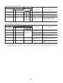
Tools exclusive for R410A (The following tools for R410A are required.)
Tools whose specifications are changed for R410A and their interchangeability
R410A
air conditioner installation
No.
Used tool
Usage
Conventional air
conditioner installation
Existence of
new equipment
for R410A
Whether conventional equipment
can be used
Whether conventional
equipment can be used
c
Flare tool
Pipe flaring
Yes
*(Note)
Yes
d
Copper pipe gauge for
adjusting projection margin
Flaring by conventional
flare tool
Yes
*(Note)
*(Note)
e
Torque wrench
Tightening of flare nut
Yes
No
No
f
Gauge manifold
Yes
No
No
g
Charge hose
Evacuating, refrigerant
charge, run check, etc.
h
Vacuum pump adapter
Vacuum evacuating
Yes
No
Yes
i
Electronic balance for
refrigerant charging
Refrigerant charge
Yes
Yes
Yes
j
Refrigerant cylinder
Refrigerant charge
Yes
No
No
k
Leakage detector
Gas leakage check
Yes
No
Yes
(Note) When flaring is carried out for R410A using the conventional flare tools, adjustment of projection
margin is necessary. For this adjustment, a copper pipe gauge, etc. are necessary.
General tools (Conventional tools can be used.)
In addition to the above exclusive tools, the following equipments which serve also for R22 are necessary
as the general tools.
1) Vacuum pump. Use vacuum pump by
attaching vacuum pump adapter.
7) Screwdriver (+, –)
2) Torque wrench
8) Spanner or Monkey wrench
3) Pipe cutter
9) Hole core drill
4) Reamer
10) Hexagon wrench (Opposite side 4mm)
5) Pipe bender
11) Tape measure
6) Level vial
12) Metal saw
Also prepare the following equipments for other installation method and run check.
1) Clamp meter
3) Insulation resistance tester (Megger)
2) Thermometer
4) Electroscope
–7–
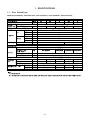
1. SPACIFICATIONS
1-1. Slim Ducted Type
MMD-AP0074SPH2UL, AP0094SPH2UL, AP0124SPH2UL, AP0154SPH2UL, AP0184SPH2UL
!" !" #
&
(
$)
*
*# $)
!
*
(
+ $
!
) -
/
0)) ."
12)3"4
/ 2 - & .
5 )
38) )
* 19# )4
() 0) :
12)3"4 1;4
< &- . .
$
> 1>4 %?
%
=
) /) ,
. .
'
'
'
'
'
'
,
,
.#
$
' $5
'
'
'
)1&4
)1&4
% %
% % % % %
1/
4 6 6
/) 7
7
7
7
7
7
7
7
7
7
>!1!: ) ,@ - *6 ' *4
% + 6//(A(3
9
1;4 9 ) .
1;4 + : - :# )
) : ) , .# #, –8–
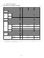
1-2. High Static Ducted Type
MMD- AP0304H2UL, AP0364H2UL, AP0484H2UL
Model name
MMD-
AP0304H2UL
AP0364H2UL
AP0484H2UL
Cooling Capacity
kBtu/h
30
36
48
Heating Capacity
kBtu/h
34
40
54
Power supply
Electrical
characteristics Power consumption
230V (208/230V) 1phase 60Hz
kW
0.38/0.41
Zinc hot dipping steel plate
Appearance
Height
Unit
Dimension
Packing
Total Weight
15.0
In
33.5
47.2
Width
In
Depth
In
26.0
Height
In
17.0
Width
In
Depth
In
42.6
56.4
31.9
Unit
lb
128
Packed unit
lb
141
154
176
Heat exchanger
Finned tube
Fan
Centrifugal fan
Standard air flow
Factory setting
(208/230V)
260
In WG
0.641/0.814
0.296/0.519
External
208V
static
pressure (*1) (High tap/Mid tap/Low tap) (*3)
In WG
1.075 - 0.641 - 0.287
0.606 - 0.296 - Non
230V
(High tap/Mid tap/Low tap) (*3)
In WG
1.175 - 0.814 - 0.506
0.801 - 0.519 - 0.114
Air flow limit
Lower limit
cfm
755.2
988.2
Upper limit
cfm
1132.8
1447.1
Air filter
Connecting
pipe
1235
926
W
Motor output
Fan unit
cfm
Field supply
Gas side
In
5/8"
Liquid side
In
3/8"
Drain port (Nominal dia.)
In
VP25(Polyvinyl chloride tube: External Dia.1-1/4 Internal Dia.1)
208V
(High/Mid/Low)
dB(A)
49.5/45/41
47/44/ -
230V
(High/Mid/Low)
dB(A)
51/47/43
49/46/43
Sound pressure level (*2)
Note
(*1) Non attached filter
(*2) The actual values in an external opeating environment are generally higher than the indicated values due to the contribution from ambient noise.
(*3) The tap is set by wire connection change of fan motor.
–9–
³
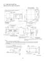
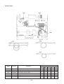
2. CONSTRUCTION VIEWS
(EXTERNAL VIEWS)
2-1. Slim Ducted Type
MMD- AP0074SPH2UL, MMD- AP0094SPH2UL, MMD- AP0124SPH2UL
– 10 –
MMD- AP0154SPH2UL, MMD- AP0184SPH2UL
– 11 –
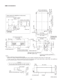
2-2. High Static Ducted Type
MMD- AP0304H2UL, MMD- AP0364H2UL
– 12 –
MMD- AP0484H2UL
– 13 –
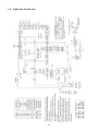
3. WIRING DIAGRAM
3-1. Slim Ducted Type
– 14 –
3-2. High Static Ducted Type
– 15 –
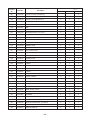
4. PARTS RATING
4-1. Slim Ducted Type
Model name
MMD-AP
0074SPH2UL
0094SPH2UL
Fan motor
0124SPH2UL
0154SPH2UL
0184SPH2UL
SWF-340U60-1A
ADP-1406
Drain pump motor
Float switch
FS-0218-102
Pulse motor
EFM-MD12TF-1
EDM-B25YGTF-3
Pulse motor valve
EDM-B40YGTF-3
Lead wire length : 6.1 in (155mm)
TA sensor
TC1 sensor
Ø4, Lead wire length : 47.2 in (1200mm), Vinyl tube (Blue)
TC2 sensor
Ø6, Lead wire length : 47.2 in (1200mm), Vinyl tube (Black)
TCJ sensor
Ø6, Lead wire length : 47.2 in (1200mm), Vinyl tube (Red)
4-2. High Static Ducted Type
Model name
MMD-AP
Fan motor
Running capacitor
0304H2UL
0364H2UL
??????????????
STF-230U260-4C
AC450V, 13µF
EFM-MD12TF-1
EDM-B40YGTF-2
EDM-B60YGTF-1
TT-12
Transformer
TA sensor
??????????????
STF-230U260-4B
AC400V, 10µF
Pulse motor
Pulse motor valve
0484H2UL
Lead wire length : 47.2 in (1200mm)
TC1 sensor
Ø4, Lead wire length : 47.2 in (1200mm), Vinyl tube (Blue)
TC2 sensor
Ø6, Lead wire length : 47.2 in (1200mm), Vinyl tube (Black)
TCJ sensor
Ø6, Lead wire length : 47.2 in (1200mm), Vinyl tube (Red)
– 16 –
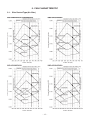
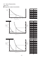
5. FAN CHARACTERISTIC
5-1. Slim Ducted Type (No filter)
– 17 –
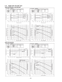
5-2. High Static Ducted Type
– 18 –
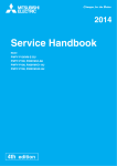
6. REFRIGERATING CYCLE DIAGRAM
Liquid side Gas side
Strainer
Capillary tube
Air heat exchanger
at indoor side
Pulse Motor
Valve (PMV)
Strainer
Sensor
(TCJ)
Sensor
(TC2)
Fan
Sensor
(TC1)
Sensor
(TA)
Functional part name
M
Fan motor
Functional outline
Pulse Motor Valve
PMV
(Connector CN082 (6P): Blue)
1) Controls super heat in cooling operation
2) Controls under cool in heating operation
3) Recovers refrigerant oil in cooling operation
4) Recovers refrigerant oil in heating operation
Temp. sensor
1. TA
(Connector CN104 (2P): Yellow)
1) Detects indoor suction temperature
2. TC1
(Connector CN100 (3P): Brown)
1) Controls PMV super heat in cooling operation
3. TC2
(Connector CN101 (2P): Black)
1) Controls PMV under cool in heating operation
4. TCJ
(Connector CN102 (2P): Red)
1) Controls PMV super heat in cooling operation
– 19 –
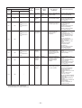
7. CONTROL OUTLINE
No.
1
2
Item
When power
supply is reset
Operation
mode selection
1) Distinction of outdoor unit
When the power supply is reset, the outdoors are
distinguished and the control is selected according to the
distinguished result.
2) Setting of indoor fan speed and existence of air direction
adjustment
Based on EEPROM data, select setting of the indoor fan
speed and the existence of air direction adjustment.
3) If resetting the power supply during occurrence of a trouble,
the check code is once cleared. After ON/OFF button of the
remote controller was pushed and the operation was resumed, if the abnormal status continues, the check code is
again displayed on the remote controller.
Control outline
STOP
Room temp.
control
Air speed (rpm)/
Air direction adjustment
1) Based on the operation mode selecting command from the
remote controller, the operation mode is selected.
Remote controller
command
3
Remarks
Outline of specifications
Air conditioner stops.
FAN
Fan operation
DRY
Drying operation
COOL
Cooling operation
HEAT
Heating operation
1) Adjustment range: Remote controller setup temperature (°F [°C] )
COOL/DRY
HEAT
Wired type
64°F [18°C] to 84°F [29°C]
64°F [18°C] to 84°C [29°C]
Wireless type
64°F [18°C] to 86°F [30°C]
61°F [16°C] to 86°F [30°C]
2) Using the Item code 06, the setup temperature in heating
operation can be corrected.
Setup data
0
2
4
6
Setup temp.
Correction
+0°F
[+0°C]
+3.6°F
[+2°C]
+7.2°F
[+4°C]
+10.8°F
[+6°C]
Setting at shipment
Setup data
2
– 20 –
Shift of suction
temperature in heating
operation
Except while sensor of
the remote controller is
controlled
(Code No. [32], “0001”)
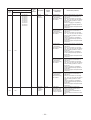
No.
4
Item
Automatic
capacity control
Outline of specifications
1) Based on the difference between Ta and Ts, the
operation capacity is determined by the outdoor unit.
COOL
Ta
˚F (˚C)
+3.6 (+2)
SB
Ts
S9
S7
Ts
–1.8 (–1)
S5
S3
–1.8 (–1)
Air speed
selection
Ta
˚F (˚C)
+1.8 (+1)
SD
+1.8 (+1)
5
Remarks
S0
–3.6 (–2)
HEAT
S3 S0
S5
S7
S9
SB
Ts: Setup temp.
Ta: Room temp.
SD
SF
1) Operation with (HH), (H), (L) or [AUTO] mode is carried
out by the command from the remote controller.
2) When the air speed mode [AUTO] is selected, the air
speed varies by the difference between Ta and Ts.
HH > H+ > H > L+ > L > UL
<COOL>
Ta ˚F (˚C)
HH
<HH>
A
B
C
H+ <HH>
D
+5.4 (+3.0)
+4.5 (+2.5)
+3.6 (+2.0)
+2.7 (+1.5)
+1.8 (+1.0)
+0.9 (+0.5)
Tsc
–0.9 (–0.5)
H <HH>
L+ <H+>
E
L <H>
L <H>
L <L+>
F
G
< > : Indicate automatic cooling.
• Controlling operation in case when thermo of
remote controller works is same as a case when
thermo of the body works.
• If the air speed has been changed once, it is not
changed for 3 minutes. However when the air
volume is exchanged, the air speed changes.
• When cooling operation has started, select a
downward slope for the air speed, that is, the high
position.
• If the temperature is just on the difference boundary, the air speed does not change.
– 21 –
Code No. 32
0000: Body thermo.
(Main unit)
0001: Remote controller
thermo.
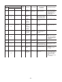
No.
5
Item
Air speed
selection
(Continued)
Outline of specifications
Remarks
<HEAT>
Ta ˚F (˚C)
L <L+>
(–0.9) –1.8 [(–0.5) –1.0]
L+ <H>
(0) Tsh
E
H <H+>
(+0.9) +1.8 [(+0.5) +1.0]
H+
<HH>
(+1.8) +3.6 [(+1.0) +2.0]
HH
<HH>
(+2.7) +5.4 [(+1.5) +3.0]
(+3.6) +7.2 [(+2.0) +4.0]
D
C
B
A
< > : Indicate automatic heating.
Body thermostat works.
Remote controller thermostat works.
Value in the parentheses indicates one when thermostat of
the remote controller works.
Value without parentheses indicates one when thermostat of
the body works.
• If the air speed has been changed once, it is not changed
for 1 minute. However when the air speed exchanged, the
air speed changes.
• When heating operation has started, select an upward
slope for the air speed, that is, the high position.
• If the temperature is just on the difference boundary, the
air speed does not change.
• In TC2 ≥ 140°F[60°C], the air speed increases by 1 step.
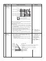
6
Prevention of
cold air
discharge
1. In heating operation, the higher temperature of TC2 sensor
and TCJ sensor is compared with temperature of TC1
sensor and then the lower temperature is used to set the
upper limit of the fan tap.
• When B zone has continued for 6 minutes, the operation shifts to C zone.
• In defrost time, the control point is set to +10.8°F[6°C].
˚F (˚C)
90 (32)
86 (30)
82 (28)
E
79 (26)
68 (20)
61 (16)
• TCJ: Temperature of
indoor heat
exchanger sensor
• In D and E zones,
priority is given to
remote controller air
speed setup.
” is dis• In A zone “
played.
A zone: OFF
B zone:
Over 79˚F (26˚C), below 82˚F (28˚C), ULTRA LOW (LL)
C zone:
Over 82˚F (28˚C), below 86˚F (30˚C), LOW (L)
D zone:
Over 86˚F (30˚C), below 90˚F (32˚C), MED (H)
E zone: HIGH (HH)
D
C
TC2: Indoor heat
exchanger sensor
temperature
B
A
– 22 –
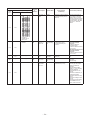
No.
Item
7
Freeze prevention
control
(Low temp. release)
Remarks
Outline of specifications
1. In all cooling operation, the air conditioner
operates as de-scribed below based upon temp.
detected by TC1, TC2 and TCJ sensors.
• When “J” zone is detected for 5 minutes, the
thermostat is forcedly off.
• In “K” zone, the timer count is interrupted, and held.
• When “I” zone is detected, the timer is cleared
and the operation returns to the normal operation.
• If “J” zone continues, operation of the indoor fan in
LOW mode continues until it reaches the “I” zone.
It is reset when the following conditions are
satisfied.
TC1: Temperature of indoor
heat exchanger sensor
Reset conditions
1) TC1 > 54°F [12°C] and TC2 > 54°F [12°C] and
TCJ > 54°F [12°C].
2) 20 minutes passed after stop.
˚F
(˚C)
I
P1
Q1
K
J
TC1
TC2, TCJ
P1
50°C [10°C]
41°C [5°C]
14°C
[–10°C]
Q1
32°F [0°C]
7°F [–14°C]
a
( ) value:
When the power supply is
turned on, the forced
thermo OFF if the temperature is less than this indicated temperature.
2. In all cooling operation, the air conditioner operates as described below based upon temp.
detected by TC2 and TCJ sensors.
• When “M” zone is detected for 30 minutes, the
thermostat is forcedly off.
• In “N” zone, the timer count is interrupted and held.
• When shifting to “M” zone again, the timer count
restarts and continues.
• If “L” zone is detected, the timer is cleared and
the operation returns to normal operation.
Reset conditions
1) TC1 > 54°F [12°C] and TC2 > 54°F [12°C] and
TCJ > 54°F [12°C].
2) 20 minutes passed after stop.
˚F
(˚C)
P2
Q2
8
Recovery control
for cooling oil
(Refrigerant)
L
N
M
TC2, TCJ
P2
41°F
Q2
28°F [–2.0°C]
[5°C]
The indoor unit which is under STOP/Thermo-OFF
status or which operates in [FAN] mode performs the
following controls when it received the cooling oil
(Refrigerant) recovery signal from the outdoor unit.
1) Opens PMV of the indoor unit with a constant
opening degree.
2) Operates the drain pump for approx. 1 minute
during recovery control and after finish of control.
– 23 –
∗ In a Model without TC2,
TC2 is not judged.
• Recovery operation is
usually performed every
2 hours 5 minuts.
No.
Item
Outline of specifications
Remarks
9
Recovery control
for heating
refrigerant (Oil)
The indoor unit which is under STOP/Thermo-OFF
status or which operates in [FAN] mode performs the
following controls when it received the heating refrigerant (Oil) recovery signal from the outdoor unit.
1) Opens PMV of the indoor unit with a constant
opening degree.
2) Detects temperature of TC2 and then closes PMV.
• The indoor unit which is
under thermo-OFF (COOL)
status or which operates in
[FAN] mode stops the indoor
fan and displays [READY ].
• Recovery operation is usually
performed every 1 hour.
(When there is even 1
indoor unit which the
thermo unit is off)
10
Compensation
control for short
intermittent
operation
1) For 3 minutes after start of operation, the operation is forcedly continued even if the unit enters in
Thermo-OFF condition.
2) However the thermostat is OFF giving prior to
COOL/HEAT selection, READY for operation
and protective control.
Usually the priority is given to
5 minutes at outdoor controller
side.
11
Drain pump
control
1) In cooling operation, this control anytime operates
the drain pump.
2) During operation of the drain pump, if the float
switch operates, the drain pump continuously
operates and a check code is issued.
3) During stop status of the drain pump, if the float
switch operates, the thermostat is forcedly off and
this control operates the drain pump.
After continuous operation of the float switch for
approx. 5 minutes, this control stops the operation
and a check code is issued.
Check Code [P10]
12
Display of filter
sign [
]
∗ Separately set
type
TCB-AX21UL
is prepared.
1) The filter sign is displayed with LC by sending the
filter-reset signal to the remote controller when the
specified time (150H/2500H) elapsed as a result of
integration of the operation time of the indoor fan.
2) The integrated timer is cleared when the filter-reset
signal is received from the remote controller.
In this time, if the specified time elapsed, the counted
time is reset and the LC display is deleted.
[
Filter time
2500H
– 24 –
FILTER] goes on.
No.
Item
Outline of specifications
13
Display of
[READY]
[HEAT READY]
< READY> Displayed on the remote controller
1) When the following check codes are indicated
• Open phase of power supply wiring [P05] was detected.
• There is an indoor unit that detected the indoor overflow
[P10].
• There is an indoor unit that detected the interlock alarm
[L30].
2) During Force Thermo-OFF
• [COOL/DRY] operation is unavailable because the other
indoor unit operates with [HEAT] mode.
• [HEAT] operation is unavailable because COOL priority
(SW11-bit1 of the Outdoor I/F P. C. board is ON) is set and
the other indoor unit operates with [COOL/DRY] mode.
3) The above indoor units that cannot operate stay in
Thermo-OFF status.
4) The indoor fan stops because the system performs
[Recovery operation for heating refrigerant (Oil)].
• <READY
> display
No display for wireless
type remote controller
<HEAT READY> Displayed on the remote controller
1. Normal thermo. OFF
• During heating, the indoor unit goes thermo OFF as the
heating temperature setting is reached.
2. During heating, the fan rotates at a breeze speed
(UL or lower) or remains stationary to prevent cold air
from being discharged (including defrosting operation).
3. Forced thermo OFF
• “HEAT” operation is unavailable because at least one
indoor unit is operating in “COOL/DRY” mode under
priority cooling setting (bit 1 of SW11 on outdoor I/FP.C.
board ON).
• <HEAT READY
display
14
Selection of
central control
mode
Remarks
>
1) Selection of the contents that can be operated by the remote controller at the indoor
unit side is possible according to setting at the central controller side.
2) Setting contents
• In case of TCC-LINK central control
Operation on RBC-AMT32UL
Operation from
TCC-LINK
central control
ON/OFF
setting
Operation
selection
Timer
setting
Temp.
setting
Air speed
setting
Air direction
setting
Individual
{
{
{
{
{
{
{
{
{
{
{
{
{
{
{
{
[Central 1]
[Central 2]
[Central 3]
[Central 4]
({: Operation possible
×
×
{
{
×
×
×
×
×
{
{
×: Operation impossible)
– 25 –
×
×
{
On
RBC-AMT32UL
[Central control]
display
No.
15
Item
DC motor
Outline of specifications
Remarks
1) When the fan stator, positioning is performed for the
starter and the rotor. (Vibrate slightly)
2) DC motor operates according to the command from
the indoor controller.
(Note) If the fan rotates by entry of outside air, etc while
the air conditioner stopped, the indoor unit may
operate as the fan motor stops.
(Note) If the fan lock was detected, the operation of the
indoor unit stops and the error is displayed.
(Note) If the incorrect duct design was found during
installation work or you carelessly opened the
service panel (drain pump) of the main unit during
operation, the check code [P12] is output and the
motor stops.
16
Save operation
1) The save operation starts when
remotecontroller is turned on.
SAVE
button on the
2) While the save operation is performed,
segment
goes on the screen of the wired remote controller.
3) The request capacity ratio is restricted to approx. 75%
during save operation.
4) If the save operation was validated, the contents are
held during the operation stop, the operation mode
change and the resetting of power supply. Therefore
the operation at the next time also will be activated
with “Save operation is valid”.
– 26 –
Check code [P12]
Indoor unit
#1
– 27 –
Indoor
fan
motor
Drain
pump
PMV
DC
280V
Power supply circuit
MCU
Fan motor
control circuit
DC5V
DC12V
A
MCU
Remote
controller
communication
circuit
B
U1
Indoor/outdoor communication
U2
U2
Outdoor
unit
Power source
208/230-1-60
L1
U1
L2
HA
Float input
TCJ sensor
TC2 sensor
TC1 sensor
TA sensor
EEPROM
Power
supply
circuit
DC5V
Key switch
Function setting
AC
BUS
In operation
synchronization communication
Alarm
signal input circuit
circuit
Getting ready
Thermostat ON
COOL
HEAT
FAN
External output
Indoor control P. C. board (MCC-1402)
DC20V
CPU
Remote controller
communication circuit
EEPROM
Driver
Outdoor
unit
B
Power
source
Outdoor
unit
U1 U2
L2
Sameas left
#3 A
U1 U2
L2
L1
Power
source
L1
B
Sameas left
#2 A
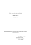
Up to 8 units can be
connected.
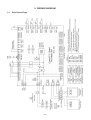
8-1-1.
Display
LED
Display
LCD
Main (Simple) wired remote controller (up to 2 units)
8. APPLIED CONTROL AND FUNCTION
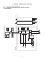
8-1. Indoor Controller Block Diagram
When Main (Simple) Wired Remote Controller Connected
<Slim Ducted Type>
Indoor unit
#1
– 28 –
Indoor
fan
motor
PMV
Transformer
Power supply circuit
Fan motor
relay circuit
DC5V
DC12V
DC20V
CPU
A
CPU
H8/3039
Remote
controller
communication
circuit
B
U1
Indoor/outdoor communication
U2
U2
Outdoor
unit
Power source
208/230-1-60
L1
U1
L2
HA
TCJ sensor
TC2 sensor
TC1 sensor
TA sensor
EEPROM
Power
supply
circuit
DC5V
Key switch
Function setting
AC
BUS
In operation
synchronization communication
Alarm
signal input circuit
circuit
Getting ready
Thermostat ON
COOL
HEAT
FAN
External output
Indoor control P. C. board (MCC-1403)
Driver
Remote controller
communication circuit
EEPROM
Display
LED
Display
LCD
Main (Simple) wired remote controller (up to 2 units)
Outdoor
unit
B
Power
source
Outdoor
unit
U1 U2
L2
Sameas left
#3 A
U1 U2
L2
L1
Power
source
L1
B
Sameas left
#2 A
Up to 8 units can be
connected.
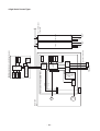
<High Static Ducted Type>
Indoor unit
#1
– 29 –
Indoor
fan
motor
Louver
motor
PMV
DC
280V
Power supply circuit
DC5V
MCU
Fan motor
control circuit
DC12V
DC20V
A
MCU
Remote
controller
communication
circuit
B
HA
Float input
TCJ sensor
TC2 sensor
TC1 sensor
TA sensor
EEPROM
Sensor P. C. board
Wireless remote controller kit
CPU
Display LED
Function
setting SW
Remote controller Emergency
communication
operation SW
circuit
Sensor circuit
Buzzer
DC5V
Power
supply circuit
Indoor/outdoor communication
U2
U2
Outdoor
unit
U1
L2
Power source
208/230-1-60
L1
U1
External
output
AC
BUS
In operation
synchronization communication
Alarm
circuit
Getting ready signal input circuit
Thermostat ON
COOL
HEAT
FAN
Indoor control P. C. board (MCC-1402)
Driver
B
U1 U2
B
U1 U2
Outdoor
unit
L2
Power
source
L1
Sameas left
#3 A
Up to 8 units can be
connected.
Outdoor
unit
L2
Power
source
L1
Sameas left
#2 A
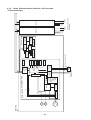
8-1-2.
When Wireless Remote Controller Kit Connected
<Slim Ducted Type>
Indoor unit
#1
– 30 –
Indoor
fan
motor
PMV
Transformer
Power supply circuit
Fan motor
control circuit
DC5V
DC12V
DC20V
In operation
Alarm
Getting ready
Thermostat ON
COOL
HEAT
FAN
External
output
L1
B
L2
U1
U2
BUS
communication
circuit
CPU
H8/3039
Remote
controller
communication
circuit
AC
synchronization
signal input circuit
Driver
HA
TCJ sensor
TC2 sensor
TC1 sensor
TA sensor
EEPROM
U1
Sensor P. C. board
Wireless remote controller kit
Display section
Remote controller
communication
circuit
Sensor circuit
Indoor/outdoor communication
U2
Outdoor
unit
Power source
208/230-1-60
Indoor control P.C. board (MCC-1403)
A
B
Outdoor
unit
U1 U2
L2
Power
source
L1
Sameas left
#2 A
B
Outdoor
unit
U1 U2
L2
Power
source
L1
Sameas left
#3 A
Up to 8 units can be
connected.
<High Static Ducted Type>
Indoor unit
#1
– 31 –
Indoor
fan
motor
Drain
pump
PMV
DC
280V
Power supply circuit
Fan motor
control circuit
MCU
CPU
TMP88CH External output
47FG
(TMP88PH
47FG)
DC5V
DC12V
L1
B
L2
CPU
Display LED
Function
setting SW
Emergency
operation SW
Sensor P. C. board
Wireless remote controller kit
Remote controller
communication
circuit
Sensor circuit
Buzzer
DC5V
Power
supply circuit
Indoor/outdoor communication
U2
U2
Outdoor
unit
U1
U1
HA
Float input
TCJ sensor
TC2 sensor
TC1 sensor
TA sensor
EEPROM
Power
supply
circuit
BUS
communication
circuit
MCU
Key switch
Function setting
DC5V
Remote
controller
communication
circuit
AC
synchronization
signal input circuit
A
Power source
208/230-1-60
Indoor control P. C. board (MCC-1402)
DC20V
CPU
Remote controller
communication circuit
EEPROM
Display
LED
Display
LCD
Main (Simple) wired remote controller (up to 2 units)
Driver
B
Outdoor
unit
Power
source
U1 U2
L2
Up to 8 units can be
connected.
Outdoor
unit
B
Sameas left
#3 A
U1 U2
L1
L2
Power
source
L1
Sameas left
#2 A
8-1-3.
When Both Wired (Simple) Remote Controller and
Wireless Remote Controller Kit Connected
<Slim Ducted Type>
Indoor unit
#1
– 32 –
Indoor
fan
motor
PMV
Transformer
Power supply circuit
Fan motor
control circuit
DC5V
DC12V
DC20V
In operation
Alarm
Getting ready
Thermostat ON
COOL
HEAT
FAN
External
output
CPU
L1
B
L2
U1
U2
BUS
communication
circuit
CPU
H8/3039
Remote
controller
communication
circuit
AC
synchronization
signal input circuit
A
HA
TCJ sensor
TC2 sensor
TC1 sensor
TA sensor
EEPROM
Power
supply
circuit
DC5V
Key switch
Function setting
Wireless remote controller kit
Display section
Remote controller
communication
circuit
Sensor circuit
Indoor/outdoor communication
U1
U2
Outdoor
unit
Power source
208/230-1-60
Indoor control P.C. board (MCC-1403)
Driver
Remote controller
communication circuit
EEPROM
Display
LED
Display
LCD
Main (Simple) wired remote controller (up to 2 units)
B
Outdoor
unit
U1 U2
L2
Power
source
L1
Sameas left
#2 A
B
Outdoor
unit
U1 U2
L2
Power
source
L1
Sameas left
#3 A
Up to 8 units can be
connected.
<High Static Ducted Type>
– 33 –
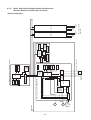
Float SW
/CN34, DC12V
DC fan return
/CN334
PMV output
/CN82, DC12V
DC fan output
/CN333
Optional output
/CN60, DC12V
TC1 sensor
/CN100, DC5V
External error imput
/CN80
TC2 sensor
/CN101, DC5V
TCJ sensor
/CN102, DC5V
EXCT
/CN73, DC5V
DISP
/CN72, DC5V
CHK
/CN71, DC5V
HA (T10)
/CN61, DC12V
TA sensor
/CN104, DC5V
Fan drive
/CN32, DC12V
Microcomputer operation LED
/D02
Indoor/Outdoor communication
(Also used for communication of the
central control system)
/CN40
Remote controller
/CN41
Drain pump output
/CN68
Remote controller
power supply LED
/D203
Optional
power supply
/CN309
AC 208/230V
Power supply
/CN67
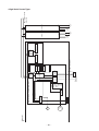
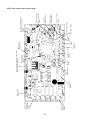
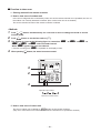
8-1-4. Indoor Printed Circuit Board
MCC-1402 <Slim ducted type>
Optional
power supply
/CN309
Power supply
transformer
(Primary side)
/CN074
Power supply
/CN067
AC fan output
/CN083
EXCT
/CN073, DC5V
TA sensor
/CN104
– 34 –
TCJ sensor
/CN102
TC1 sensor
/CN100
TC2 sensor
/CN101
PMV output
/CN082, DC12V
External error input
/CN080
Microcomputer
operation LED
/D002
Power supply transformer (Secondary side)
(AC11V, 14V, 20V) /CN075
CHK /CN071, DC5V
DISP /CN72, DC5V
Remote controller
/CN41
Optional output
/CN060, DC12V
HA (T10)
/CN061, DC12V
Remote controller
power supply LED
/D203
Also used for communication of
the central control system
/CN040
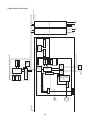
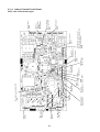
MCC-1403 <High static ducted type>
8-1-5. P.C. Board Optional Switch/Connector Specifications
Function
Connector No.
Fan output
Pin No.
1
CN32
HA
Optional
output
CN60
Output
CHK
Operation
check
CN71
DISP
Display mode
CN72
EXCT
Demand
CN73
Start / stop input for HA (J01: In place / Removed =
Pulse input (factory default) / Step input)
0V(COM)
3
Remote controller disabling
inpu
Enables / disables start / stop control via remote
controller
4
In-operation output
ON during operation (HA answerback signal)
5
DC12 V (COM)
6
Alarm output
1
DC12 V (COM)
2
Defrosting output
ON while outdoor unit defrosted
3
Thermostat ON output
ON while real thermostat ON (compressor ON)
Cooling output
ON while air conditioner in cooling or related operation
(COOL, DRY or cooling under AUTO mode)
Heating output
ON while air conditioner in heating operation (HEAT or
heating under AUTO mode)
Fan output
ON while indoor fan ON (air cleaner in use or via
interlock wiring)
1
DC12 V (COM)
2
DC12 V (COM)
Generates test code L30 and automatically shuts down
air conditioner (only if condition persists
for 1 minute)
3
External error input
1
Check mode input
4
6
CN80
Start / stop inpu
2
5
External error
input
Remarks
Factory default setting: ON when indoor unit in
operation and OFF when indoor unit at rest
* Fan can be operated on its own by pressing FAN
button on remote controller (DN = 31)
2
1
CN61
Specification
DC12 V
ON while alarm ON
0V
2
1
Display mode input
2
0V
1
Demand input
2
0V
Used for indoor operation check (prescribed operational
status output, such as indoor fan "H" or drain pump ON,
to be generated without communication with outdoor
unit or remote controller)
Product display mode - Communication just between
indoor unit and remote controller enabled (upon turning
on of power) Timer short-circuited out (always)
Imposes thermostat OFF on indoor unit
– 35 –
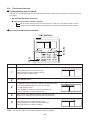
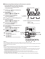
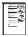
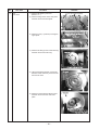
8-2. Functions at test run
Cooling/Heating test run check
The test run for cooling/heating can be performed from either indoor remote controller or outdoor interface
P.C. board.
1. Start/Finish operation of test run
~ Test run from indoor remote controller
Wired remote controller: Refer to the below item of “Test run” of the wired remote controller.
Wireless remote controller: Refer to the next page item of “Test run” of the wireless remote controller.
In case of wired remote controller
<RBC-AMT32UL>
TEMP.
1,
5
Procedure
1
2
FILTER
RESET TEST
ON / OFF
TIMER SET
FAN
MODE
TIME
SAVE
VENT
SWING/FIX
UNIT LOUVER
SET
CL
2,
4
3
Operation contents
Push [TEST] button for 4 seconds or more.
TEST
[TEST] is displayed at the display part and
the mode enters in TEST mode.
Push [ON/OFF] button.
Change the mode from [COOL] to [HEAT] using [MODE] button.
3
• Do not use [MODE] button for other mode except
[COOL]/[HEAT] modes.
• The temperature cannot be adjusted during test run.
• The error detection is performed as usual.
4
After test run, push [ON/OFF] button to stop the operation.
(Display on the display part is same to that in Procedure 1 .)
5
Push [TEST] button to clear the TEST mode.
([TEST] display in the display part disappears and
status becomes the normal stop status.)
Note)
The test run returns to the normal operation after 60 minutes.
– 36 –
TEST
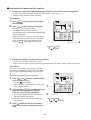
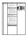
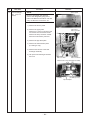
<In case of wireless remote controller (TCB-AX21UL)>
Procedure
Description
Turn on power of the air conditioner.
1
The operation is not accepted for 5 minutes when power has been turned on at first time after installation,
and 1 minute when power has been turned on at the next time and after.
After the specified time has passed, perform a test operation.
2
Push [Start/Stop] button and change the operation mode to [COOL] or [HEAT] with [Mode] button.
Then change the fan speed to [High] using [Fan] button.
Test cooling operation
Test heating operation
3
Set temperature to [64°F (18°C)] using
[Temperature set] button.
Set temperature to [86°F (30°C)] using
[Temperature set] button.
4
After checking the receiving sound “Pi”,
immediately push [Temperature set] button to
set to [66°F (19°C)]
After checking the receiving sound “Pi”,
immediately push [Temperature set] button to
set to [84°F (29°C)].
5
After checking the receiving sound “Pi”,
immediately push [Temperature set] button to
set to [64°F (18°C)].
After checking the receiving sound “Pi”,
immediately push [Temperature set] button to
set to [86°F (30°C)].
Then repeat the procedure
6
4→5→4→5.
After approx. 10 seconds, all the display lamps on the sensor part of wireless remote controller,
[Operation] (Green), [Timer] (Green), and [Ready] (Yellow) flash and the air conditioner starts operation.
If the lamps do not flash, repeat the procedure
7
2 and after.
After the test operation, push [Start/Stop] button to stop the operation.
Be sure to set the
air speed to [High]
2
3, 4, 5, 6
2, 7
– 37 –
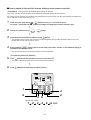
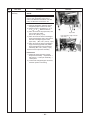
Check function for operation of indoor unit (Functions at indoor unit side)
This function is provided to check the operation of the indoor unit singly without communication with the remote
controller or the outdoor unit. This function can be used regardless of operation or stop of the system.
However, if using this function for a long time, a trouble of the equipment may be caused. Limit using this
function within several minutes.
[How to operate]
1) Short-circuit CHK pin (CN71 on the indoor P.C. board).
The operation mode differs according to the indoor unit status in that time.
Normal time: Both float SW and fan motor are normal.
Abnormal time: Either one of float SW or fan motor is abnormal.
2) Restricted to the normal time, if short-circuiting DISP pin (CN72 on the indoor P.C. board) in addition to
short-circuit of CHK pin (CN71 on the indoor P.C. board), the minimum opening degree (30pls) can be
set to the indoor PMV only.
When open DISP pin, the maximum opening degree (1500pls) can be obtained again.
[How to clear]
Open CHK pin. While the system is operating, it stops once but automatically returns to operation after
several minutes.
Short-circuit of CHK pin(CN71)
Normal time
Abnormal time
DISP pin open(CN71)
DISP pin short circuit(CN71)
(H)
(H)
Stop
Max. opening degree (1500pls)
Min. opening degree (30pls)
Min. opening degree (30pls)
ON
ON
ON
Communication
All ignored
All ignored
All ignored
P.C. board LED
Lights
Lights
Flashes
Fan motor
Indoor PMV (∗)
Drain pump
– 38 –
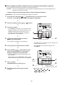
8-3. Method to Set Indoor Unit Function DN Code
(When performing this task, be sure to use a wired remote controller.)
<Procedure> To be performed only when system at rest
1
2
3
SET
CL
10
CODE No.
Push the
+
+
buttons simultaneously and hold for at
least 4 seconds.
The unit No. displayed first is the address of the header indoor unit in
group control.
Then the fan and louver of the selected indoor unit move.
SET DATA SETTING TEST
00 01
UNIT No.
1-1
R.C.
No.
TEMP.
UNIT LOUVER
Each time the “Select unit” side of the
button is pushed,
one of the indoor unit Nos. under group control is displayed in
turn. Then the fan of the selected indoor unit move.
ON / OFF
TIMER SET
FAN
TIME
FILTER
RESET TEST
SET
CL
MODE
SAVE
VENT
SWING/FIX
UNIT LOUVER
TEMP.
button to select the CODE No. (DN code) of the
Use the
desired function.
4
Use the
button to select the desired SET DATA associated
with the selected function.
5
button. (The display changes from flashing to
Push the
steady.)
• To change the selected indoor unit, go back to step 2.
• To change the selected function, go back to step 3.
6
When the
SET
SET
button is pushed, the system returns to normal off state.
– 39 –
5
3
6
4
1
2
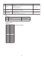
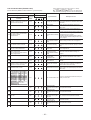
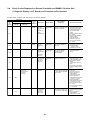
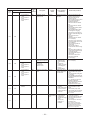
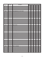
Functio n CODE No. (DN Code) Table (Includes All Functions Needed to Perform Applied Control on Site)
DN
Item
Descrip tio n
0001: 150H
0003: 5000H
Filter display delay timer 0000: None
01
0002: 2500H
0004: 10000H
02
03
04
Dirty state of filter
0000: Standard
0001: High degree of dirt (Half of standard time)
0000: Standard
Central control address
0001: No.1 unit
0099: Unfixed
0064: No.64 unit
0099: Unfixed
Specific indoor unit
priority
0000: No priority
0001: Priority
0000: No priority
Heating temp shift
0000: No shift
0002: +2˚C(+3.6˚F)
0001: +1˚C(+1.8˚F)
0010: +10˚C(+18˚F)
(Up to +6 recommended)
0002: +2˚C(+3.6˚F)
(Floor type 0000: 0˚C)
06
0d
0F
10
11
At sh ip men t
According to type
to
to
Existence of [AUTO]
mode
0000: Provided
0001: Not provided (Automatic selection from connected outdoor unit)
0001: Not provided
Cooling only
0000: Heat pump
0001: Cooling only (No display of [AUTO] [HEAT])
0000: Heat pump
Type
0005: Slim Ducted Type
0006: High static Ducted Type
According to model
type
Indoor unit capacity
0000: Unfixed
0001 to 0034
According to capacity
type
12 Line address
0001: No.1 unit
to
0030: No.30 unit
0099: Unfixed
13 Indoor unit address
0001: No.1 unit
to
0064: No.64 unit
0099: Unfixed
Group address
0000: Individual
0002: Follower unit of group
0001: Header unit of group
0099: Unfixed
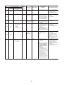
28
Automatic restart of
power failure
0000: None
0001: Restart
0001: Restart
2A
Selection of option/error
input (CN213)
0000: Filter input
0002: External interlock
0001: Alarm input (Option parts)
0002: External interlock
2E
HA terminal (CN61)
select
0000: Usual
0002: Fire alarm input
0001: Leaving-ON prevention control 0000: Usual
(HA terminal)
31 Ventilating fan control
0000: Unavailable
0001: Available
32 TA sensor selection
0000: Body TA sensor
0001: Remote controller sensor
0000: Body TA sensor
33 Temperature unit select
0000: ˚C
0001: ˚F : (at factory shipment)
0001:
: ˚F
14
– 40 –
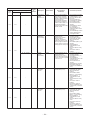
0000: Unavailable
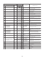
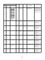
DN
Item
Description
At shipment
Slim Ducted
0001: Standard 1 (factory defoult)
0003: High static pressure 2
0006: High static pressure 3
Static pressure
5d
selection
0001: Standard
Timer setting
0000: Available (can be performed)
60 (wired remote controller)
0001: Unavailable (cannot be performed)
92
Outside interlock
release condition
0000: Available
0000: Operation stop
0001: Release communication signal receive
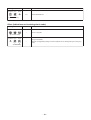
Type
DN code “10”
Value
Type
0005
Slim Ducted
0006
High static Ducted
Model
***SPH2UL
MMD-AP
***H2UL
MMD-AP
*1 Default value stored in EEPROM mounted on service P.C. board
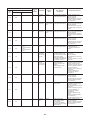
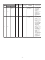
Indoor Unit Capacity
DN code “11”
Value
Capacity
0000*
Invalid
0001
007 type
0003
009 type
0005
012 type
0007
015 type
0009
018 type
0010
021 type
0011
024 type
0012
027 type
0013
030 type
0015
036 type
0016
042 type
0017
048 type
0018
056 type
0021
072 type
0023
096 type
~
–
*1 Default value stored in EEPROM
mounted on service P.C. board
– 41 –
0000: Operation stop
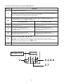
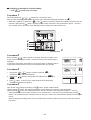
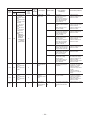
8-4. Applied Control in Indoor Unit
Remote location ON/OFF control box (TCB-IFCB-4UL)
[Wiring and setup]
• Use the exclusive connector for connection with the indoor control P.C. board.
• In a group control, the system can operate when connecting with any indoor unit (Control P.C. board) in
the group. However when taking out the operation/error signal from the other unit, it is necessary to take
out from each unit individually.
1. Control items
1) Start/Stop input signal : Operation start/stop in unit
2) Operation signal
: Output during normal operation
3) Error signal
: Output during alarm
(Serial communication error or indoor/outdoor protective device) operation
2. Wiring diagram using remote control interface (TCB-IFCB-4UL)
Input
Output
IFCB-4UL : No voltage ON/OFF serial signal
No voltage contact for operation, error display
Contact capacity: Below Max. AC240V 0.5A
Indoor control P.C. board
Start/Stop input
COM (GND)
Remote controller prohibition/clear input
Operation signal output
COM (+12V)
Error signal output
Remote location ON/OFF control box
(TCB-IFCB-4UL)
1
2
3
4
5
6
1
2
3
4
ON/OFF serial
signal input
COM
CN06
1
2
3
4
5
6
CN61
T10
(YEL)
Operation signal output
CN13
Error signal output
Power supply 208/230-1-60
– 42 –
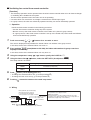
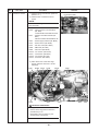
Ventilating fan control from remote controller
[Function]
• The start/stop operation can be operated from the wired remote controller when air to air heat exchanger
or ventilating fan is installed in the system.
• The fan can be operated even if the indoor unit is not operating.
• Use a fan which can receive the no-voltage A contact as an outside input signal.
• In a group control, the units are collectively operated and they can not be individually operated.
1. Operation
Handle a wired remote controller in the following procedure.
∗ Use the wired remote controller during stop of the system.
∗ Be sure to set up the wired remote controller to the header unit. (Same in group control)
∗ In a group control, if the wired remote controller is set up to the header unit, both header and follower
units are simultaneously operable.
1
Push concurrently
SET
+
CL
+
buttons for 4 seconds or more.
The unit No. displayed firstly indicates the header indoor unit address in the group control.
In this time, the fan of the selected indoor unit turns on.
2
3
4
5
6
Every pushing
button(button at left side), the indoor unit numbers in group control are
displayed successively.
In this time, the fan of the selected indoor unit only turns on.
UNIT LOUVER
Using the temperature setup
button, specify the CODE No. 31 .
/
Using the timer time
/
button, select the SET DATA. (At shipment: 0000 )
The setup data are as follows:
SET DATA
Handling of operation of air to air heat exchanger or ventilating fan
0000
0001
Unavailable (At shipment)
Available
Push
button. (OK if display goes on.)
• To change the selected indoor unit, go to the procedure 2 ).
• To change the item to be set up, go to the procedure 3 ).
SET
Pushing
TEST
returns the status to the usual stop status.
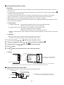
2. Wiring
Relay (DC12V, procured locally)
Corresponds to the relay up
to one that the rated current
of the operation coil is approx. 75mA
CN32 1 1
FAN DRIVE
(2P WHI) 2 2
Outside control
input of fan
To terminal
Indoor control
P.C. board
Note) Determine the cable length between the
indoor control P.C. board and the relay within 2m.
– 43 –
Corresponds up to a relay in which rated current of
the operation coil is approx. 75mA
Other type models:
Correspond up to a relay in which rated current of the
operation coil is approx. 16mA (Does not correspond to a
terminal block type relay on the market.)
Leaving-ON prevention control
[Function]
• This function controls the indoor units individually. It is connected with cable to the control P.C. board of
the indoor unit.
• In a group control, it is connected with cable to the indoor unit (Control P.C. board), and the CODE No. 2E
is set to the connected indoor unit.
• It is used when the start operation from outside if unnecessary but the stop operation is necessary.
• Using a card switch box, card lock, etc, the forgotten-OFF of the indoor unit can be protected.
• When inserting a card, start/stop operation from the remote controller is allowed.
• When taking out a card, the system stops if the indoor unit is operating and start/stop operation from the
remote controller is forbidden.
1. Control items
1) Outside contact ON : The start/stop operation from the remote controller is allowed.
(Status that card is inserted in the card switch box)
2) Outside contact OFF : If the indoor unit is operating, it is stopped forcedly.
(Start/Stop prohibited to remote controller)
(Status that card is taken out from the card switch box)
* When the card switch box does not perform the above contact operation, convert it using a relay with b
contact.
2. Operation
Handle the wired remote controller switch in the following procedure.
* Use the wired remote controller switch during stop of the system.
1
2
3
4
5
Push concurrently
SET
+
CL
+
Using the temperature setup
Using the timer time
/
buttons for 4 seconds or more.
/
button, specify the CODE No. 2E .
button, set 0001 to the setup data.
Push
SET
button.
Push
TEST
button. (The status returns to the usual stop status.)
3. Wiring
Relay (procured locally)
CN61
T10 1 1
(YEL) 2 2
3
4
5
6
3
4
5
6
* In the figure, the contact indicates
a status that the card is taken out.
Indoor control P.C. board
Power supply
Outside contact (Card switch box, etc: Procured locally)
Note) Determine the cable length between the indoor control P.C. board and the relay within 2m.
Power peak-cut from indoor unit
When the relay is turned on, a forced thermostat-OFF operation starts.
• Wiring example
CN73
Relay (procured locally)
1 1
EXCT 2 2
(2P plug: RED)
Relay coil signal
Note) Determine the cable length between the indoor or
outdoor control P.C. board and the relay within 2m.
Indoor control P.C. board
– 44 –
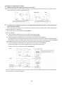
Address setup (Manual setting from Wired remote controller)
In case that addresses of the indoor units will be
determined prior to piping work after wiring work
• Set an indoor unit per a remote controller.
• Turn on power supply.
1
2
3
4
5
6
7
8
9
10
11
CL
(Example of 2-lines cabling)
(Real line: Wiring, Broken line: Refrigerant pipe)
Outdoor
Push
+
+
buttons simultaneously
for 4 seconds or more.
SET
TEST
(Line address)
Using the temperature setup
/
buttons, set 12 to the CODE No.
Using timer time
/
set the line address.
Push
SET
Indoor
Indoor
Indoor
Indoor
1
2
2
1
3
2
2
1
2
2
2
2
Follower
unit
button. (OK when display goes on.)
Header unit
For the above example, perform setting by connecting singly the
wired remote controller without remote controller inter-unit cable.
Group address
Individual
: 0000
Header unit : 0001
Follower unit : 0002
Using timer time
/
buttons,
set 1 to the line address.
SET
Indoor
Line address → 1
Indoor unit address → 1
Group address → 1
buttons,
(Indoor unit address)
Using the temperature setup
/
buttons, set 13 to the CODE No.
Push
Outdoor
In case of group control
button. (OK when display goes on.)
(Group address)
Using the temperature setup
/
buttons, set 14 to the CODE No.
Using timer time
/
buttons,
set 0000 to Individual, 0001 to
Header unit and 0002 to follower unit.
Push
button.
(OK when display goes on.)
SET
TEMP.
2, 5, 8
END 11
Push
button.
Setup completes.
(The status returns to the usual stop status.)
FILTER
RESET TEST
ON / OFF
TIMER SET
FAN
MODE
TIME
SAVE
VENT
SWING/FIX
UNIT LOUVER
SET
CL
TEST
1
3, 6, 9
4, 7, 10
<Operation procedure>
1
7
2
8
3
9
4 5 6
10 11 END
Note 1)
When setting the line address from the remote controller, do not use Address 29 and 30.
As they are addresses which cannot be set to the outdoor unit, if they are set, the check code [E04] (Indoor/Outdoor
communication circuit error) is issued.
Note 2)
When an address was manually set from the remote controller and the central control over the refrigerant lines is
carried out, perform the following setting for the Header unit of each line.
• Set the line address for every line using SW13 and 14 on the interface P.C. board of the Header unit in each line.
• Except the least line address No., turn off SW30-2 on the interface P.C. board of the Header units in the lines
connected to the identical central control.
(Draw the terminal resistances of indoor/outdoor and central control line wirings together.)
• For each refrigerant line, connect the relay connector between Header unit [U1U2] and [U3U4] terminals.
• After then set the central control address.
(For setting of the central control address, refer to the Installation manual for the central control equipment.)
– 45 –
Confirmation of indoor unit No. position
1. To know the indoor unit addresses though position of the indoor unit is recognized
• In case of individual operation (Wired remote controller : indoor unit = 1 : 1)
(Follow to the procedure during operation)
<Procedure>
1
2
Push ON / OFF button (button at left side) if
the unit stops.
Push
button (button at left side).
Unit No. 1-1 is displayed on LCD.
(It disappears after several seconds.)
The displayed unit No. indicate line address and
indoor unit address.
(When other indoor units are connected to the
identical remote controller (Group control unit),
other unit numbers are also displayed every
UNIT LOUVER
button(button at left side).
pushing
UNIT LOUVER
F
ON / OFF
TEMP.
TIMER SET
FAN
TIME
FILTER
RESET TEST
SET
CL
MODE
SAVE
VENT
SWING/FIX
UNIT LOUVER
1
Operation
2
<Operation procedure>
1
2 END
2. To know the position of indoor unit by address
• To confirm the unit No. in the group control
(Follow to the procedure during operation) (in this procedure, the indoor units in group control stop.)
<Procedure>
The indoor unit numbers in the group control are
successively displayed, and fan, louver, and drain
pump of the corresponding indoor unit are turned
on.
(Follow to the procedure during operation)
1
2
3
VENT
Push
and
buttons simultaneously
for 4 seconds or more.
• Unit No.
is displayed.
• Fans and louvers of all the indoor units in the
group control operate.
TEST
Every pushing
button(button at left
side), the unit numbers in the group
control are successively displayed.
• The unit No. displayed at the first time indicates the master unit address.
• Fan and louver of the selected indoor unit
only operate.
ON / OFF
TEMP.
1
FILTER
RESET TEST
UNIT LOUVER
TIMER SET
FAN
TIME
SAVE
VENT
SWING/FIX
UNIT LOUVER
SET
CL
2
3
<Operation procedure>
Push
button to finish the procedure.
All the indoor units in the group control
stop.
TEST
– 46 –
MODE
1
2
3 END
How to check all the unit No. from an arbitrary wired remote controller
<Procedure> Carry out this procedure during stop of system.
The indoor unit No. and the position in the identical refrigerant piping can be checked.
An outdoor unit is selected, the identical refrigerant piping and the indoor unit No. are displayed one after the
other, and then its fan and louver are on.
1
2
3
4
Push the timer time button
+
simultaneously for 4 seconds or more.
First line 1 and CODE No. AC (Address Change) are displayed. (Select outdoor unit.)
TEST
Ø
Select line address using
/
UNIT LOUVER
button.
SWING/FIX
Ø
Determine the selected line address using
button.
• The address of the indoor unit connected to the refrigerant piping of the selected outdoor unit is displayed and the fan and the louver are on.
SET
Ø
Every pushing
button (button at left side), the indoor unit No. in the identical piping is
displayed one after the other.
• Only fan and louver of the selected indoor unit start operation.
UNIT LOUVER
[To select the other line address]
5
6
Push
button and the operation returns to Procedure 2.
* The indoor address of other line can be continuously checked.
CL
Ø
Push
TEST
button and then the procedure finishes.
ON / OFF
TEMP.
TIMER SET
FAN
TIME
1
FILTER
RESET TEST
6
SET
CL
MODE
SAVE
VENT
SWING/FIX
UNIT LOUVER
4
2
3 5
<Operation procedure>
1
2
3
4
5
– 47 –
6
END
How to change an indoor unit address by using a wired remote control
Use this method to change the address of indoor units (one to one or group control) that have had the original
address set automatically.
This procedure must be done while the units are not operating.
1
2
CL
Simultaneously push and hold the “SET
”, “CL
”, and “TEST
” buttons for more than 4
seconds. If there are 2 or more units in a group, the first “UNIT No.” indicated is the header
unit.
SET
TEST
Ø
Push the left end of the “UNIT LOUVER
” button repeatedly to select an indoor unit
address to change. If 2 or more units are controlled in a group the fan and louvers of the
selected unit will be energized.
UNIT LOUVER
Ø
3
4
5
6
7
8
Push the TEMP.
/
buttons repeatedly to select 13 for CODE No.
Ø
Push the TIME
tion.
/
buttons repeatedly to change the value indicated in the SET DATA sec-
Ø
Push the “SET
SET
” button, to save address.
Ø
Push left and of the “UNIT LOUVER
” button repeatedly to select another indoor unit
addresses to change. Repeat steps 4 through 6 to continue changing indoor unit address and
make each of them unique.
UNIT LOUVER
Push the left end of the “UNIT LOUVER
dresses.
UNIT LOUVER
” button to review/confirm the revised ad-
Ø
If the addresses have been changed correctly, push the “TEST
dure.
TEST
” button to finish the proce-
CODE No.
SET DATA SETTING
UNIT No.
R.C.
No.
TEMP.
3
5
8
ON / OFF
TIMER SET
4
TIME
FILTER
RESET TEST
SET
CL
Finish
1
2, 6, 7
– 48 –
How to change all indoor addresses from an arbitrary wired remote controller
(It is possible when setting has finished by automatic addresses.)
Contents: The indoor unit addresses in each identical refrigerant piping line can be changed from an
arbitrary wired remote controller.
~ Enter in address check/change mode and then change the address.
<Procedure> Carry out this procedure during stop of system.
1
2
3
4
5
6
7
8
Push the timer time button
+
simultaneously for 4 seconds or more.
First line 1 and CODE No. AC (Address Change) are displayed.
TEST
Ø
Select line address using
UNIT LOUVER
/
SWING/FIX
button.
Ø
Push the
button.
• The address of the indoor unit connected to the
refrigerant piping of the selected outdoor unit is
displayed and the fan and the louver are on.
First the current indoor address is displayed.
(Line address is not displayed.)
SET
ON / OFF
TEMP.
1
FILTER
RESET TEST
TIMER SET
FAN
MODE
TIME
SAVE
VENT
SWING/FIX
UNIT LOUVER
SET
CL
Ø
3
button push up/down the indoor
address of the SET DATA.
The set data is changed to a new address.
TIME
SET
2
If the UNIT No. is not call up here, the outdoor unit
in that line does not exist.
CL
Push
button to select a line again in the
Procedure 2.
Ø
Push
Cancel of line selection
button to determine the set data.
Ø
Every pushing
button (button at left
side), the indoor unit No. in the identical
piping is displayed one after the other.
• Only fan and louver of the selected indoor unit
start operation.
Repeat the Procedures 4 to 6 to change all the
indoor addresses so that they are not duplicated.
UNIT LOUVER
Ø
Push
button.
(All the indications of LCD go on.)
SET
Ø
Push
button and then the procedure
finishes.
TEST
ON / OFF
TEMP.
TIMER SET
8
FAN
TIME
FILTER
RESET TEST
Finish
SET
CL
MODE
SAVE
VENT
SWING/FIX
UNIT LOUVER
6
5
When you want to
complete the setting
<Operation procedure>
1
6
– 49 –
4
2
7
3
8
4
END
5
7
Function to clear error
1. Clearing method from remote controller
~ How to clear error of outdoor unit
In the unit of refrigerant line connected by indoor unit of the remote controller to be operated, the error of
the outdoor unit currently detected is cleared. (Error of the indoor unit is not cleared.)
The service monitor function of the remote controller is utilized.
<Method>
1
2
3
4
CL
Push
+
buttons simultaneously for 4 seconds or more to change the mode to service
monitor mode.
Push
TEST
TEMP.
button to set the item code to [FF ].
The display of A part in the following figure is counted as “0005 ” → “0004 ” → “0003 ” →
“0002 ” → “0001 ” → “0000 ” with 5-seconds interval.
When “0000 ” appear, the error was cleared.
∗ However counting from “0005 ” is repeated on the display screen.
When pushing
TEST
button, the status becomes normal.
3
ON / OFF
TEMP.
2
TIMER SET
TIME
FILTER
RESET TEST
SET
CL
FAN
MODE
SAVE
VENT
SWING/FIX
UNIT LOUVER
1
4
<Operation procedure>
1
2
3
4
Returns to normal status
~ How to clear error of indoor unit
The error of indoor unit is cleared by
button of the remote controller.
(Only error of the indoor unit connected with remote controller to be operated is cleared.)
ON / OFF
– 50 –
Monitoring function of remote controller switch
When using the remote controller (Model Name: RBC-AMT32UL), the following monitoring
function can be utilized.
Calling of display
<Contents>
The temperature of each sensor of the remote controller, indoor unit and outdoor unit and the operating
status can be checked by calling the service monitor mode from the remote controller.
<Procedure>
1
2
3
4
CL
Push
+
buttons simultaneously for 4 seconds or more to call up the service monitor mode.
The service monitor goes on and firstly the temperature of the CODE No. 00 is displayed.
TEST
Ø
Push
button to change CODE No.
(CODE No.) to the CODE No. to be monitored.
For display code, refer to the following table.
TEMP.
Ø
Push
button (button at left side) to change to item to be monitored.
The sensor temperature of indoor unit or outdoor unit in its refrigerant line and the operating
status are monitored.
UNIT LOUVER
Ø
Push
TEST
button to return the status to the normal display.
ON / OFF
TEMP.
2
TIMER SET
TIME
FILTER
RESET TEST
4
1
SET
CL
FAN
MODE
SAVE
VENT
SWING/FIX
UNIT LOUVER
Returns to normal display
<Operation procedure>
1
2
3
– 51 –
4
3
System data
Indoor unit data *2
CODE No.
Display format
Unit
00
Room temperature (During control)
Data name
×1
˚F
01
Room temperature (Remote controller)
×1
˚F
02
Indoor suction temperature (TA)
×1
˚F
03
Indoor coil temperature (TCJ)
×1
˚F
04
Indoor coil temperature (TC2)
×1
˚F
05
Indoor coil temperature (TC1)
×1
˚F
06
Indoor discharge temperature (TF) *1
08
Indoor PMV opening
0A
Outdoor unit individual data 1 *3
[0075]=75˚F(24˚C)
×1
˚F
pls
[0150]=1500pulse
No. of connected indoor units
×1
unit
[0024]=24 units
0B
Total capacity of connected indoor units
×10
ton
[0215]=21.5ton
0C
No. of connected outdoor units
×1
unit
[0002]=2 units
0D
Total capacity of outdoor units
×10
ton
[0160]=16ton
Display format
Unit
Data name
U2
10
20
High-pressure sensor detention pressure (Pd)
×10
psi
11
21
Low-pressure sensor detention pressure (Ps)
×10
psi
12
22
Compressor 1 discharge temperature (Td1)
×1
˚F
13
23
Compressor 2 discharge temperature (Td2)
×1
˚F
14
24
Compressor 3 discharge temperature (Td3)
×1
˚F
15
25
Suction temperature (TS)
×1
˚F
16
26
Outdoor coil temperature 1 (TE1)
×1
˚F
17
27
Outdoor coil temperature 2 (TE2)
×1
˚F
18
28
Temperature at liquid side (TL)
×1
˚F
19
29
Outside ambient temperature (TO)
×1
˚F
1A
2A
PMV1 + 2 opening
×1
pls
1B
2B
PMV4 opening
×1
pls
1C
2C
Compressor 1 current (I1)
×10
A
1D
2D
Compressor 2 current (I2)
×10
A
1E
2E
Compressor 3 current (I3)
×10
A
1F
2F
Outdoor fan current (IFan)
×10
A
Display format
Unit
CODE No.
Outdoor unit individual data 2 *4
[0081]=71˚F(27˚C)
×1/10
CODE No.
U1
Remote controller display example
Data name
U1
U2
50
60
Compressor 1 revolutions
×10
rps
51
61
Compressor 2 revolutions
×10
rps
52
62
Compressor 3 revolutions
×10
rps
53
63
Outdoor fan mode
×1
mode
54
64
Compressor IPDU 1 heat sink temperature
×1
˚F
55
65
Compressor IPDU 2 heat sink temperature
×1
˚F
56
66
Compressor IPDU 3 heat sink temperature
×1
˚F
57
67
Outdoor fan IPDU heat sink temperature
×1
˚F
58
-
Heating/cooling recovery controlled *5
59
-
Pressure release *5
5A
-
Discharge temperature release *5
5B
-
Follower unit release
(U2/U2/U4 outdoor units) *5
5F
6F
Outdoor unit capacity
0: Normal
1: Recovery controlled
Remote controller display example
[4350]=435psi
[0075]=75˚F(24˚C)
[0500] =500pulse
[0135]=13.5A
Remote controller display example
[0642]=64.2rps
[0058]= 58 mode
[0075]=75˚F(24˚C)
[0010]=Heating recovery controlled
[0001]=Cooling recovery controlled
[0010]=Pressure release controlled
0: Normal
1: Release controlled
×10
ton
[0001]=Discharge temperature release controlled
[0100]=U2 outdoor unit release controlled
[0010]=U3 outdoor unit release controlled
[0001]=U4 outdoor unit release controlled
[0080]=8ton
*1 Only a part of indoor unit types is installed with the discharge temperature sensor. This temperature is not displayed for other types.
*2 When the units are connected to a group, data of the header indoor unit only can be displayed.
*3 The first digit of an CODE No. indicates the outdoor unit number.
*4 The upper digit of an CODE No. -4 indicates the outdoor unit number.
1 , 5 ... U1 outdoor unit (Header unit)
2 , 6 ... U2 outdoor unit (Follower unit 1)
*5 Only the CODE No. 5* of U1 outdoor unit (Header unit) is displayed.
– 52 –
Changing of settings for Celsius display
• Push
ON / OFF
button if the unit stops.
Procedure 1
Push simultaneously TEST + SET + CL buttons for 4 seconds or more.
After a while, the display part flashes as shown right. Check the displayed CODE No. is [10 ].
TEST
• When the CODE No. is other than [10 ], push
button to erase the display and repeat procedure from the
TEST
first step. (After pushing
button, operation of the remote controller is not accepted for approx. 1 minute.)
(For a group control, No. of the firstly displayed indoor unit becomes the header unit.)
3
4
5
6
1
2
Procedure 2
Every pushing UNIT LOUVER button (button at left side), the indoor unit No. in the
group control is displayed in order. Select the indoor unit of which setup is
changed.
In this time, the position of the indoor unit of which setup is changed can be
confirmed because fan and louver of the selected indoor unit operate.
CODE No.
SET DATA SETTING
UNIT No.
R.C.
No.
CODE No.
Procedure 3
SET DATA SETTING
UNIT No.
R.C.
1. Using temp. setup TEMP. buttons, specify CODE No. [33 ].
(CODE No. [33 ]: Fahrenheit display)
2. Using timer
[0000. ]
TIME
No.
buttons, change the line address from [0001 ] to
SETTING
3. Push SET button. In this time, the setup finishes when the display
changes from flashing to lighting.
Procedure 4
TEST
After check of the changed contents, push
button. (Setup is determined.)
TEST
When pushing
button, the display disappears and the status becomes the usual stop status.
(When pushing TEST button the operation from the remote controller is not accepted for approx. 1 minute.)
TEST
• If the operation from the remote controller is not accepted even 1 minute or more passed after pushing
button, it is considered that the address setup is incorrect. In this case, the automatic address must be again
set up.
When changing the settings from Celsius to Fahrenheit indication, follow to the reverse order of the above
procedure.
– 53 –
9. TROUBLESHOOTING
9-1. Overview
(1) Before engaging in troubleshooting
(a) Applicable models
All Super Module Multi (SMMS-i) models.
(Indoor units: MMD-APOOO, Outdoor units: MMY-MAPOOO)
(b) Tools and measuring devices required
Screwdrivers (Philips, flat head), spanners, long-nose pliers, nipper, pin to push reset switch, etc.
Multimeter, thermometer, pressure gauge, etc.
(c) Things to check prior to troubleshooting (behaviors listed below are normal)
NO.
Behavior
Possible cause
A compressor would not start
Could it just be the 3-minute delay period (3 minutes after compressor
shutdown)?
Could it just be the air conditioner having gone thermo OFF?
Could it just be the air conditioner operating in fan mode or put on the timer?
Could it just be the system going through initial communication?
An indoor fan would not start
Could it just be cold air discharge prevention control, which is part of
heating?
An outdoor fan would not start or would
change speed for no reason
Could it just be cooling operation under low outside temperature
conditions?
Could it just be defrosting operation?
An indoor fan would not stop
Could it just be the elimination of residual heat being performed as part of
the air conditioner shutdown process after heating operation?
The air conditioner would not respond to a
start/stop command from a remote controller
Could it just be the air conditioner operation under external or remote
control?
1
2
3
4
5
(2) Troubleshooting procedure
When a fault occurs, proceed with troubleshooting in accordance with the procedure shown below.
"E28" error
Fault
Investigate check code
displayed on interface P.C. board
of header unit
Investigate check code
displayed on interface P.C.
board of relevant follower unit
Check fault site or
faulty part
Any other fault
NOTE
Rather than a genuine fault (see the List of Check Codes below), the problem could have been caused by a
microprocessor malfunction attributable to a poor quality of the power source or an external noise. Check for
possible noise sources, and shield the remote controller wiring and signal wires as necessary.
– 54 –
9-2. Troubleshooting Method
The remote controllers (main remote controller and central control remote controller) and the interface P.C. board
of an outdoor unit are provided with an LCD display (remote controller) or a 7-segment display (outdoor interface
P.C. board) to display operational status. Using this self-diagnosis feature, the fault site/faulty part may be identified
in the event of a fault by following the method described below.
The list below summarizes check codes detected by various devices. Analyze the check code according to where it is displayed and work out
the nature of the fault in consultation with the list.
• When investigating a fault on the basis of a display provided on the indoor remote controller or TCC-LINK central control remote controller See the “TCC-LINK remote control or main remote controller display” section of the list.
• When investigating a fault on the basis of a display provided on an outdoor unit - See the “Outdoor 7-segment display” section of the list.
• When investigating a fault on the basis of a wireless remote controller-controlled indoor unit - See the “Light sensor indicator light block”
section of the list.
List of Check Codes (Indoor Unit)
IPDU: Intelligent Power Drive Unit (Inverter P.C. board)
: Lighting,
: Flashing,
: Goes off
ALT.: Flashing is alternately when there are two flashing LED
SIM: Simultaneous flashing when there are two flashing LED
(Error detected by indoor unit)
Check code
Display of receiving unit
Outdoor 7-segment display
TCC-LINK central
control or main remote
controller display
Sub-c ode
Indicator light block
Operation Timer Ready
Typical fault site
Description of error
Flash
E03
–
–
Indoor-remote controller periodic
communication error
Communication from remote controller or network
adaptor has been lost (so has central control
communication).
E04
–
–
Indoor-outdoor periodic
communication error
Signals are not being received from outdoor unit.
Duplicated indoor address
Indoor unit detects address identical to its own.
E08
E08 Duplicated indoor address
E10
–
–
Indoor inter-MCU communication MCU communication between main controller and
error
motor microcontroller is faulty.
E18
–
–
Error in periodic communication
between indoor header and
follower unit
Periodic communication between indoor header
and follower units cannot be maintained.
F01
–
–
ALT
Indoor heat exchanger
temperature sensor (TCJ) error
Heat exchanger temperature sensor (TCJ) has
been open/short-circuited.
F02
–
–
ALT
Indoor heat exchanger
temperature sensor (TC2) error
Heat exchanger temperature sensor (TC2) has
been open/short-circuited.
F03
–
–
ALT
Indoor heat exchanger
temperature sensor (TC1) error
Heat exchanger temperature sensor (TC1) has
been open/short-circuited.
F10
–
–
ALT
Ambient temperature sensor (TA) Ambient temperature sensor (TA) has been open/
error
short-circuited.
F11
–
–
ALT
Discharge temperature sensor
(TF) error
F29
–
–
SIM P.C. board or other indoor error
L03
–
–
SIM
Duplicated indoor group header
unit
L07
–
–
SIM
Connection of group control cable There is at least one stand-alone indoor unit to
to stand-alone indoor unit
which group control cable is connected.
L08
L08
–
SIM Indoor group address not set
Address setting has not been performed for one or
more indoor units (also detected at outdoor unit
end).
L09
–
–
SIM Indoor capacity not set
Capacity setting has not been performed for indoor
unit.
L20
–
–
SIM Duplicated central control address
There is duplication in central control address
setting.
L30
P01
P10
L30 Detected indoor unit No.
–
–
P10 Detected indoor unit No.
SIM
Indoor external error input
(interlock)
Discharge temperature sensor (TF) has been open/
short-circuited.
Indoor EEPROM is abnormal (some other error may
be detected).
There is more than one header unit in group.
Unit shutdown has been caused by external error
input (CN213)
ALT Indoor AC fan error
Indoor AC fan error is detected (activation of fan
motor thermal relay).
ALT Indoor overflow error
Float switch has been activated.
P12
–
–
ALT Indoor DC fan error
Indoor DC fan error (e.g. overcurrent or lock-up) is
detected. In the case of incorrect duct setting
performed at installation or if an access panel for
the maintenance is removed while indoor unit is in
operation
P31
–
–
ALT Other indoor unit error
Follower unit cannot be operated due to header unit
alarm (E03/L03/L07/L08).
– 55 –
(Error detected by main remote controller)
Check code
Display of receiving unit
Outdoor 7-segment display
Main remote controller
Sub-code
Indicator light block
Operation Timer Ready
Typical fault site
Description of error
Flash
E01
–
–
No master remote controller,
faulty remote controller
communication (reception)
E02
–
–
Faulty remote controller
Signals cannot be transmitted to indoor unit.
communication (transmission)
–
Duplicated master remote
controller
E09
–
Signals cannot be received from indoor unit;
master remote controller has not been set
(including two remote controller control).
Both remote controllers have been set as
master remote controller in two remote
controller control (alarm and shutdown for
header unit and continued operation for
follower unit)
(Error detected by central control device)
Display of receiving unit
Check code
Outdoor 7-segment display
TCC-LINK central
control
Sub-code
C05
–
–
C06
–
–
–
–
–
C12
–
–
P30
–
–
Indicator light block
Operation Timer Ready
Typical fault site
Description of error
Flash
Central control device is unable to transmit
Faulty central control
signal due to duplication of central control
communication (transmission)
device
No indication (when
main remote controller
also in use)
Faulty central control
communication (reception)
Central control device is unable to receive
signal.
Multiple network adapters
Multiple network adapters are connected to
remote controller communication line
Blanket alarm for generalpurpose device control
interface
–
As per alarm unit (see
above)
Group control follower unit
error
Device connected to general-purpose device
control interface for TCC-LINK is faulty.
Group follower unit is faulty (unit No. and
above detail [
] displayed on main remote
controller)
Note: The same error, e.g. a communication error, may result in the display of different check codes depending on the device that detects it.
Moreover, check codes detected by the main remote controller/central control device do not necessarily have a direct impact on air
conditioner operation.
– 56 –
List of Check Codes (Outdoor Unit)
IPDU: Intelligent Power Drive Unit (Inverter P.C. board)
: Lighting,
: Flashing,
: Goes off
ALT.: Flashing is alternately when there are two flashing LED
SIM: Simultaneous flashing when there are two flashing LED
(Errors detected by SMMS-i outdoor interface - typical examples)
Check code
Display of receiving unit
Outdoor 7-segment display
TCC-LINK
central control
or main remote
controller
display
Sub-code
Indicator light block
Operation Timer Ready
Typical fault site
Description of error
Flash
Indoor unit initially communicating normally fails to
Dropping out of indoor unit return signal (reduction in number of indoor units
connected).
E06
Number of indoor units from which
signal is received normally
E06
E07
–
(E04)
Indoor-outdoor
communication circuit
error
Signal cannot be transmitted to indoor units
( indoor units left without communication from
outdoor unit).
(E08)
Duplicated indoor address
More than one indoor unit is assigned same
address (also detected at indoor unit end).
01: Indoor-outdoor communication
E12 02: Outdoor-outdoor
communication
E12
• Indoor automatic address setting is started while
automatic address setting for equipment in other
Automatic address starting
refrigerant line is in progress.
• Outdoor automatic address setting is started
error
while automatic address setting for indoor units
is in progress.
E15
E15
Indoor unit not found
during automatic address
setting
Indoor unit fails to communicate while automatic
address setting for indoor units is in progress.
Combined capacity of indoor units is too large
(more than 135% of combined capacity of outdoor
units).
E08 Duplicated indoor address
–
E16
00: Overloading
01: Number of units connected
E16
Too many indoor units
connected/overloading
E19
00: No header unit
02: Two or more header units
E19
Error in number of outdoor There is no or more than one outdoor header unit
header units
in one refrigerant line.
E20
01: Connection of outdoor unit from
other refrigerant line
02: Connection of indoor unit from
other refrigerant line
E20
Connection to other
refrigerant line found
during automatic address
setting
Indoor unit from other refrigerant line is detected
while indoor automatic address setting is in
progress.
E23
–
E23
Outdoor-outdoor
communication
transmission error
Signal cannot be transmitted to other outdoor
units.
E25
–
E25
Duplicated follower
outdoor address
There is duplication in outdoor addresses set
manually.
E26
Address of outdoor unit from which
signal is not received normally
E26
Dropping out of outdoor
unit
Follower outdoor unit initially communicating
normally fails to do so (reduction in number of
follower outdoor units connected).
E28
Outdoor header unit detects fault relating to
Outdoor follower unit error follower outdoor unit (detail displayed on follower
outdoor unit).
E31
IPDU communication error
E28 Detected outdoor unit No.
A3-IPDU Fan
1 2 3 IPDU
A3-IPDU Fan
1 2 3 IPDU
E31
01
02
03
04
05
06
07
08
09
O
0A
O
0B O O
O
0C
O
0D O
O O
0E
0F O O O
O
O O
O
O
O O
O O O
O
O
O
O
O
O
O
O
O
O
There is no communication between IPDUs (P.C.
boards) in inverter box.
Circle (O):
Faulty IPDU
F04
–
F04
Outdoor discharge
Outdoor discharge temperature sensor (TD1) has
ALT temperature sensor (TD1)
been open/short-circuited.
error
F05
–
F05
Outdoor discharge
Outdoor discharge temperature sensor (TD2) has
ALT temperature sensor (TD2)
been open/short-circuited.
error
F06
Outdoor heat exchanger
Outdoor heat exchanger temperature sensors
ALT temperature sensor (TE1,
(TE1, TE2) have been open/short-circuited.
TE2) error
F06
01: TE1
02: TE2
Outdoor liquid temperature Outdoor liquid temperature sensor (TL) has been
sensor (TL) error
open/short-circuited.
F07
–
F07
ALT
F08
–
F08
Outdoor outside air
ALT temperature sensor (TO)
error
F11
–
F11
– 57 –
Outdoor outside air temperature sensor (TO) has
been open/short-circuited.
Display of receiving unit
Check code
Outdoor 7-segment display
Sub-code
TCC-LINK
central control
or main remote
controller
display
Indicator light block
Operation Timer Ready
Typical fault site
Description of error
Flash
F12
–
F12
Outdoor suction
Outdoor suction temperature sensor (TS1) has
ALT temperature sensor (TS1)
been open/short-circuited.
error
F15
–
F15
Outdoor temperature
ALT sensor (TE1, TL) wiring
error
F16
–
F16
ALT
F22
–
F22
Outdoor discharge
Outdoor discharge temperature sensor (TD3) has
ALT temperature sensor (TD3)
been open/short-circuited.
error
F23
–
F23
ALT
Low pressure sensor (Ps)
Output voltage of low pressure sensor (Ps) is zero.
error
F24
–
F24
ALT
Output voltage of high pressure sensor (Pd) is zero
High pressure sensor (Pd)
or provides abnormal readings when compressors
error
have been turned off.
F31
–
F31
SIM Outdoor EEPROM error
H05
–
H05
Outdoor discharge
Wiring/installation error or detachment of outdoor
temperature sensor (TD1) discharge temperature sensor (TD1) has been
detected.
wiring error
H06
–
H06
Activation of low-pressure Low pressure (Ps) sensor detects abnormally low
protection
operating pressure.
H07
–
H07
Low oil level protection
Temperature sensor for oil level detection (TK1-5)
detects abnormally low oil level.
01: TK1 sensor error
02: TK2 sensor error
H08 03: TK3 sensor error
04: TK4 sensor error
05: TK5 sensor error
H08
Error in temperature
sensor for oil level
detection (TK1-5)
Temperature sensor for oil level detection (TK1-5)
has been open/short-circuited.
H15
H15
Outdoor discharge
Wiring/installation error or detachment of outdoor
temperature sensor (TD2) discharge temperature sensor (TD2) has been
wiring error
detected.
01: TK1 oil circuit error
02: TK2 oil circuit error
H16 03: TK3 oil circuit error
04: TK4 oil circuit error
05: TK5 oil circuit error
H16
Oil level detection circuit
error
H25
–
H25
Outdoor discharge
Wiring/installation error or detachment of outdoor
temperature sensor (TD3) discharge temperature sensor (TD3) has been
wiring error
detected.
L04
–
L04
SIM
L05
Duplicated priority indoor
SIM unit (as displayed on
priority indoor unit)
More than one indoor unit has been set up as
priority indoor unit.
L06
SIM
Duplicated priority indoor
unit (as displayed on
indoor unit other than
priority indoor unit)
More than one indoor unit has been set up as
priority indoor unit.
SIM
Indoor group address not
set
Address setting has not been performed for one or
more indoor units (also detected at indoor end).
–
Number of priority indoor units
L06 (check code L05 or L06 depending
on individual unit)
Outdoor pressure sensor
(Pd, Ps) wiring error
Duplicated outdoor
refrigerant line address
Wiring error in outdoor temperature sensors (TE1,
TL) has been detected.
Wiring error in outdoor pressure sensors (Pd, Ps)
has been detected.
Outdoor EEPROM is faulty (alarm and shutdown
for header unit and continued operation for follower
unit)
No temperature change is detected by
temperature sensor for oil level detection (TK1-5)
despite compressor having been started.
Identical refrigerant line address has been
assigned to outdoor units belonging to different
refrigerant piping systems.
L08
–
(L08)
L10
–
L10
SIM Outdoor capacity not set
Outdoor unit capacity has not been set (after P.C.
board replacement).
L17
–
L17
SIM
Outdoor model
incompatibility error
Old model outdoor unit (prior to 3 series) has been
connected.
L18
–
L18
SIM
Cooling/heating selection
unit error
Cooling/heating cycle error resulting from piping
error is detected.
L28
–
L28
SIM
Too many outdoor units
connected
More than four outdoor units have been
connected.
– 58 –
Display of receiving unit
Check code
Outdoor 7-segment display
TCC-LINK
central control
or main remote
controller
display
Sub-code
L29
O
O
O O
O
O
O
O O
O O O
O
O
O
Operation Timer Ready
Typical fault site
Description of error
Flash
A3-IPDU Fan
1 2 3 IPDU
A3-IPDU Fan
1 2 3 IPDU
01
02
03
04
05
06
07
08
09
Indicator light block
0A
O
0B O O
0C
O
O
0D O
O O
0E
0F O O O
Circle (O):
Faulty IPDU
O
O
O
O
O
O
L29
SIM Error in number of IPDUs
There are insufficient number of IPDUs (P.C.
boards) in inverter box.
L30 Detected indoor unit No.
(L30)
SIM
Indoor unit has been shut down for external error
Indoor external error input
input in one refrigerant line (detected by indoor
(interlock)
unit).
P03
P03
ALT
Outdoor discharge (TD1)
temperature error
–
00: Open phase detected
P05 01: Compressor 1
02: Compressor 2
03: Compressor 3
01: Compressor 1
P07 02: Compressor 2
03: Compressor 3
P10 Indoor unit No. detected
P13
P15
–
01: TS condition
02: TD condition
Open phase/power failure
P05
ALT Inverter DC voltage (Vdc)
error
MG-CTT error
P07
ALT
(P10)
Heat sink overheating
error
ALT Indoor unit overflow
Outdoor liquid backflow
detection error
P13
ALT
P15
ALT Gas leak detection
Outdoor discharge temperature sensor (TD1) has
detected abnormally high temperature.
Open phase is detected when power is turned on.
Inverter DC voltage is too high (overvoltage) or too
low (undervoltage).
Temperature sensor built into IGBT (TH) detects
overheating.
Indoor unit has been shutdown in one refrigerant
line due to detection of overflow (detected by
indoor unit).
State of refrigerant cycle circuit indicates liquid
backflow operation.
Outdoor suction temperature sensor (TS1) detects
sustained and repeated high temperatures that
exceed standard value.
P17
–
P17
ALT
Outdoor discharge (TD2)
temperature error
Outdoor discharge temperature sensor (TD2)
detects abnormally high temperature.
P18
–
P18
ALT
Outdoor discharge (TD3)
temperature error
Outdoor discharge temperature sensor (TD3)
detects abnormally high temperature.
P19 Outdoor unit No. detected
P19
ALT
4-way valve reversing
error
Abnormality in refrigerating cycle is detected
during heating operation.
P20
P20
ALT
Activation of high-pressure High pressure (Pd) sensor detects high pressure
protection
that exceeds standard value.
–
MG-CTT: Magnet contactor
– 59 –
(Errors detected by IPDU featuring in SMMS-i standard outdoor unit - typical examples)
Check code
Outdoor 7-segment display
Sub-code
Display of receiving unit
TCC-LINK
central control
or main remote
controller
display
Indicator light block
Operation Timer Ready
Typical fault site
Description of error
Flash
01: Compressor 1
F13 02: Compressor 2
03: Compressor 3
F13
Error in temperature
ALT sensor built into indoor
IGBT (TH)
01: Compressor 1
H01 02: Compressor 2
03: Compressor 3
H01
Compressor breakdown
01: Compressor 1
H02 02: Compressor 2
03: Compressor 3
H02
Compressor error (lockup) Compressor lockup is detected
01: Compressor 1
H03 02: Compressor 2
03: Compressor 3
H03
Current detection circuit
error
01: Compressor 1
P04 02: Compressor 2
03: Compressor 3
P04
ALT
Activation of high-pressure
High-pressure SW is activated.
SW
01: Compressor 1
P07 02: Compressor 2
03: Compressor 3
P07
ALT
Heat sink overheating
error
0 : IGBT circuit
1 : Position detection circuit error
3 : Motor lockup error
4 : Motor current detection
C : TH sensor error
P22 D : TH sensor error
E : Inverter DC voltage error
(outdoor fan)
Note: Although letters 0 to F appear
at locations indicated by “ ”,
please ignore them.
P22
ALT Outdoor fan IPDU error
01: Compressor 1
P26 02: Compressor 2
03: Compressor 3
P26
ALT
Activation of G-Tr (IGBT)
short-circuit protection
Short-circuit protection for compressor motor
driver circuit components is activated (momentary
overcurrent).
01: Compressor 1
P29 02: Compressor 2
03: Compressor 3
P29
ALT
Compressor position
detection circuit error
Compressor motor position detection error is
detected.
Temperature sensor built into indoor IGBT (TH)
has been open/short-circuited.
Inverter current (Idc) detection circuit detects
overcurrent.
Abnormal current is detected while inverter
compressor is turned off.
Temperature sensor built into IGBT (TH) detects
overheating.
Outdoor fan IPDU detects error.
Note: The above check codes are examples only, and different check codes may be displayed depending on the outdoor unit configuration
(e.g. a Super heat recovery multi system). For details, see the service manual for the outdoor unit.
– 60 –
9-3. Troubleshooting Based on Information Displayed on
Remote Controller
Using main remote controller (RBC-AMT32UL)
(1) Checking and testing
When a fault occurs to an air conditioner, a check
code and indoor unit No. are displayed on the
display window of the remote controller.
Check codes are only displayed while the air
conditioner is in operation.
If the display has already disappeared, access
error history by following the procedure described
below.
Check code
Indoor unit No. in which
fault has occurred
(2) Error history
The error history access procedure is described below (up to four errors stored in memory).
Error history can be accessed regardless of whether the air conditioner is in operation or shut down.
<Procedure> To be performed when system at rest
1
Invoke the SERVICE CHECK mode by pushing the
+
buttons simultaneously and holding for at least 4
seconds.
The letters “
SERVICE CHECK” light up, and the check code
“01” is displayed, indicating the error history. This is
accompanied by the indoor unit No. to which the error history is
related and a check code.
2
TEMP.
2
To check other error history items, push the
button to select another check code.
TIMER SET
TIME
Check code “ 01 ” ( latest) Check code “ 04 ” (oldest )
Note: Error history contains four items.
3
When the
restored.
ON / OFF
FILTER
RESET TEST
SET
CL
FAN
MODE
SAVE
VENT
SWING/FIX
UNIT LOUVER
Normal display is restored.
button is pushed, normal display is
3 1 Steps to follow
1
2
3
REQUIREMENT
Do not push the
button as it would erase the whole error history of the indoor unit.
How to read displayed information
<7-segment display symbols>
<Corresponding alphanumerical letters>
0
1
2
3
4
5
6
7
8
9
A
– 61 –
b
C
d
E
F
H
J
L
P
Using indoor unit indicators (receiving unit light block) (wireless type)
To identify the check code, check the 7-segment display on the header unit. To check for check codes not
displayed on the 7-segment display, consult the “List of Check Codes (Indoor Unit)” in “9-2. Troubleshooting
Method”.
: Goes off
: Lighting
: Blinking (0.5 seconds)
Light block
Operation Timer
Check code
Cause of fault
Ready
–
Power turned off or error in wiring between receiving and indoor units
All lights out
Operation Timer
Ready
Blinking
Operation Timer
Ready
Blinking
Operation Timer
Ready
Alternate blinking
Operation Timer
Ready
E01
Faulty reception
E02
Faulty transmission
Receiving unit
E03
Loss of communication
E08
Duplicated indoor unit No. (address)
E09
Duplicated master remote controller
E10
Indoor unit inter-MCU communication error
Error or poor contact in wiring
between receiving and indoor
units
Setting error
E12
Automatic address starting error
E18
Error or poor contact in wiring between indoor units, indoor power turned off
E04
Error or poor contact in wiring between indoor and outdoor units
(loss of indoor-outdoor communication)
E06
Faulty reception in indoor-outdoor communication (dropping out of indoor unit)
E07
Faulty transmission in indoor-outdoor communication
E15
Indoor unit not found during automatic address setting
E16
Too many indoor units connected/overloading
E19
Error in number of outdoor header units
E20
Detection of refrigerant piping communication error during automatic address setting
E23
Faulty transmission in outdoor-outdoor communication
E25
Duplicated follower outdoor address
E26
Faulty reception in outdoor-outdoor communication, dropping out of outdoor unit
E28
Outdoor follower unit error
E31
IPDU communication error
P01
Indoor AC fan error
P10
Indoor overflow error
P12
Indoor DC fan error
P13
Outdoor liquid backflow detection error
P03
Outdoor discharge (TD1) temperature error
P04
Activation of outdoor high-pressure SW
P05
Open phase/power failure
Inverter DC voltage (Vdc) error
MG-CTT error
P07
Outdoor heat sink overheating error - Poor cooling of electrical component (IGBT) of outdoor unit
Alternate blinking
P15
Gas leak detection - insufficient refrigerant charging
P17
Outdoor discharge (TD2) temperature error
P18
Outdoor discharge (TD3) temperature error
P19
Outdoor 4-way valve reversing error
P20
Activation of high-pressure protection
P22
Outdoor fan IPDU error
P26
Outdoor G-Tr short-circuit error
P29
Compressor position detection circuit error
P31
Shutdown of other indoor unit in group due to fault (group follower unit error)
MG-CTT: Magnet contactor
– 62 –
Light block
Operation Timer
Ready
Alternate blinking
Operation Timer
Ready
Alternate blinking
Operation Timer
Check code
Cause of fault
F01
Heat exchanger temperature sensor (TCJ) error
F02
Heat exchanger temperature sensor (TC2) error
F03
Heat exchanger temperature sensor (TC1) error
F10
Ambient temperature sensor (TA) error
F11
Discharge temperature sensor (TF) error
F04
Discharge temperature sensor (TD1) error
F05
Discharge temperature sensor (TD2) error
F06
Heat exchanger temperature sensor (TE1, TE2) error
F07
Liquid temperature sensor (TL) error
F08
Outside air temperature sensor (TO) error
Indoor unit temperature sensor
errors
Outdoor unit temperature
sensor errors
F12
Suction temperature sensor (TS1) error
F13
Heat sink sensor (TH) error
F15
Wiring error in heat exchanger sensor (TE1) and liquid temperature sensor (TL)
Outdoor unit temperature sensor wiring/installation error
F16
Wiring error in outdoor high pressure sensor (Pd) and low pressure sensor (Ps)
Outdoor pressure sensor wiring error
F22
Outdoor discharge temperature sensor (TD3) error
F23
Low pressure sensor (Ps) error
F24
High pressure sensor (Pd) error
F29
Fault in indoor EEPROM
H01
Compressor breakdown
H02
Compressor lockup
H03
Current detection circuit error
H05
Wiring/installation error or detachment of outdoor discharge temperature sensor (TD1)
H06
Abnormal drop in low-pressure sensor (Ps) reading
H07
Abnormal drop in oil level
H08
Error in temperature sensor for oil level detection circuit (TK1, TK2, TK3, TK4 or TK5)
Outdoor unit pressure sensor
errors
Ready
Synchronized blinking
Operation Timer
Ready
Blinking
Operation Timer
Ready
Synchronized blinking
Operation Timer
Ready
Synchronized blinking
Outdoor unit compressorrelated errors
Protective shutdown of outdoor
unit
H15
Wiring/installation error or detachment of outdoor discharge temperature sensor (TD2)
H16
Oil level detection circuit error - Error in outdoor unit TK1, TK2, TK3, TK4 or TK5 circuit
H25
Wiring/installation error or detachment of outdoor discharge temperature sensor (TD3)
L03
Duplicated indoor group header unit
L05
Duplicated priority indoor unit (as displayed on priority indoor unit)
L06
Duplicated priority indoor unit (as displayed on indoor unit other than priority indoor unit)
L07
Connection of group control cable to stand-alone indoor unit
L08
Indoor group address not set
L09
Indoor capacity not set
L04
Duplicated outdoor refrigerant line address
L10
Outdoor capacity not set
L17
Outdoor model incompatibility error
L18
Flow selector units error
L20
Duplicated central control address
L28
Too many outdoor units connected
L29
Error in number of IPDUs
L30
Indoor external interlock error
– 63 –
Light block
Operation Timer
Check code
Cause of fault
Ready
F31
Outdoor EEPROM error
Synchronized blinking
Other (indications not involving check code)
Light block
Operation Timer
Check code
Cause of fault
Ready
–
Test run in progress
–
Setting incompatibility
(automatic cooling/heating setting for model incapable of it and heating setting for cooling-only
model)
Synchronized blinking
Operation Timer
Ready
Alternate blinking
– 64 –
9-4. Check Codes Displayed on Remote Controller and SMMS-i Outdoor Unit
(7-Segment Display on I/F Board) and Locations to Be Checked
For other types of outdoor units, refer to their own service manuals.
Check code
Main
remote
controller
E01
E02
E03
E04
Outdoor 7-segment display
Check code
–
–
–
–
Sub-code
–
Description
System status
Error detection
condition(s)
Indoor-remote
controller
communication
error
(detected at
remote
controller end)
Stop of
corresponding
unit
Communication between
indoor P.C. board and remote
controller is disrupted.
• Check remote controller
inter-unit tie cable (A/B).
• Check for broken wire or
connector bad contact.
• Check indoor power
supply.
• Check for defect in indoor
P.C. board.
• Check remote controller
address settings
(when two remote
controllers are in use).
• Check remote controller
P.C. board.
Remote
controller
Remote
controller
transmission
error
Stop of
corresponding
unit
Signal cannot be transmitted
from remote controller to
indoor unit.
• Check internal
transmission circuit of
remote controller.
--- Replace remote
controller as necessary.
Indoor
unit
Indoor-remote
controller
communication
error
(detected at
indoor end)
Stop of
corresponding
unit
There is no communication
from remote controller
(including wireless) or
network adaptor.
• Check remote controller
and network adaptor
wiring.
Indoor
unit
Indoor-outdoor
communication
circuit error
(detected at
indoor end)
Stop of
corresponding
unit
Indoor unit is not receiving
signal from outdoor unit.
• Check order in which
power was turned on for
indoor and outdoor units.
• Check indoor address
setting.
• Check indoor-outdoor tie
cable.
• Check outdoor termination
resistance setting (SW30,
Bit 2).
I/F
Dropping out of
indoor unit
All stop
Indoor unit initially
communicating normally fails
to return signal for specified
length of time.
• Check power supply to
indoor unit.
(Is power turned on?)
• Check connection of
indoor-outdoor
communication cable.
• Check connection of
communication connectors
on indoor P.C. board.
• Check connection of
communication connectors
on outdoor P.C. board.
• Check for defect in indoor
P.C. board.
• Check for defect in outdoor
P.C. board (I/F).
I/F
Indoor-outdoor
communication
circuit error
(detected at
outdoor end)
All stop
Signal cannot be transmitted
from outdoor to indoor units
for 30 seconds continuously.
• Check outdoor termination
resistance setting (SW30,
Bit 2).
• Check connection of
indoor-outdoor
communication circuit.
–
–
–
E06
E07
–
Check items (locations)
Remote
controller
–
No. of indoor
units from
which signal is
received
normally
E06
Location
of
detection
– 65 –
Check code
Main
remote
controller
Outdoor 7-segment display
Check code
Sub-code
Duplicated
indoor address
E08
E08
E09
–
–
E10
–
–
E12
E15
E12
E15
01:
Indoor-outdoor
communication
02:
Outdooroutdoor
communication
Description
System status
Error detection
condition(s)
Check items (locations)
Indoor
unit
I/F
Duplicated
indoor address
All stop
More than one indoor unit is
assigned same address.
• Check indoor addresses.
• Check for any change
made to remote controller
connection (group/
individual) since indoor
address setting.
Remote
controller
Duplicated
master remote
controller
Stop of
corresponding
unit
In two remote controller
configuration (including
wireless), both controllers are
set up as master. (Header
indoor unit is shut down with
alarm, while follower indoor
units continue operating.)
• Check remote controller
settings.
• Check remote controller
P.C. boards.
Indoor
unit
Indoor interMCU
communication
error
Stop of
corresponding
unit
Communication cannot be
established/maintained upon
turning on of power or during
communication.
• Check for defect in indoor
P.C. board
I/F
Automatic
address starting
error
All stop
• Indoor automatic address
setting is started while
automatic address setting
for equipment in other
refrigerant line is in
progress.
• Outdoor automatic
address setting is started
while automatic address
setting for indoor units is in
progress.
• Perform automatic address
setting again after
disconnecting
communication cable to
that refrigerant line.
I/F
Indoor unit not
found during
automatic
address setting
All stop
Indoor unit cannot be
detected after indoor
automatic address setting is
started.
• Check connection of
indoor-outdoor
communication line.
• Check for error in indoor
power supply system.
• Check for noise from other
devices.
• Check for power failure.
• Check for defect in indoor
P.C. board.
I/F
Too many
indoor units
connected
All stop
• Combined capacity of
indoor units exceeds 120%
of combined capacity of
outdoor units.
Note:
If this code comes up
after backup setting for
outdoor unit failure is
performed, perform “No
overloading detected”
setting.
<“No overloading detected”
setting method>
Turn on SW09/Bit 2 on I/F
P.C. board of outdoor header
unit.
• More than 48 indoor units
are connected.
• Check capacities of indoor
units connected.
• Check combined HP
capacities of indoor units.
• Check HP capacity
settings of outdoor units.
• Check No. of indoor units
connected.
• Check for defect in outdoor
P.C. board (I/F).
–
00:
Overloading
01-:
No. of units
connected
E16
Location
of
detection
E16
system including Medium
* The
Static Ducted may not
sometimes output the error
code [16] because the
microcomputer cannot judge
that even if the connection of
the indoor units was over its
maximum capacity 120%.
– 66 –
Check code
Main
remote
controller
E18
E19
E20
Outdoor 7-segment display
Check code
Sub-code
System status
Error detection
condition(s)
Check items (locations)
Indoor
unit
Error in
communication
between indoor
header and
follower units
Stop of
corresponding
unit
Periodic communication
between indoor header and
follower units cannot be
maintained.
• Check remote controller
wiring.
• Check indoor power supply
wiring.
• Check P.C. boards of
indoor units.
–
I/F
Error in number
of outdoor
header units
All stop
E19
00:
No header unit
02:
Two or more
header units
• There is more than one
outdoor header unit in one
line.
• There is no outdoor header
unit in one line.
Outdoor header unit is
outdoor unit to which indooroutdoor tie cable (U1,U2) is
connected.
• Check connection of
indoor-outdoor
communication line.
• Check for defect in outdoor
P.C. board (I/F).
01:
Connection of
outdoor unit
from other line
02:
Connection of
indoor unit from
other line
I/F
Connection to
other line found
during
automatic
address setting
All stop
Equipment from other line is
found to have been
connected when indoor
automatic address setting is
in progress.
Disconnect inter-line tie cable
in accordance with automatic
address setting method
explained in “Address
setting” section.
I/F
Outdooroutdoor
communication
transmission
error
All stop
Signal cannot be transmitted
to other outdoor units for at
least 30 seconds
continuously.
• Check power supply to
outdoor units. (Is power
turned on?)
• Check connection of tie
cables between outdoor
units for bad contact or
broken wire.
• Check communication
connectors on outdoor
P.C. boards.
• Check for defect in outdoor
P.C. board (I/F).
• Check termination
resistance setting for
communication between
outdoor units.
I/F
Duplicated
follower outdoor
address
All stop
There is duplication in
outdoor addresses set
manually.
Note:
Do not set outdoor
addresses manually.
Address of
outdoor unit
from which
signal is not
received
normally
I/F
Dropping out of
outdoor unit
All stop
Outdoor unit initially
communicating normally fails
to return signal for specified
length of time.
• Backup setting is being
used for outdoor units.
• Check power supply to
outdoor unit. (Is power
turned on?)
• Check connection of tie
cables between outdoor
units for bad contact or
broken wire.
• Check communication
connectors on outdoor
P.C. boards.
• Check for defect in outdoor
P.C. board (I/F).
Detected
outdoor unit
No.
I/F
Outdoor
follower unit
error
All stop
Outdoor header unit receives
error code from outdoor
follower unit.
• Check check code
displayed on outdoor
follower unit.
<Convenient functions>
If SW04 is pressed and held
for at least 1 second while
[E28] is displayed on the 7segmentdisplay of outdoor
header unit, the fan of the
outdoor unit that has been
shut down due to an error
comes on.
If SW04 and SW05 are
pressed simultaneously, the
fans of normal outdoor units
come on.
To stop the fan or fans, press
SW05 on its own.
E20
E23
–
E25
E25
–
E28
Description
–
E23
E26
Location
of
detection
E26
E28
– 67 –
Check code
Main
remote
controller
E31
Outdoor 7-segment display
Check code
E31
Sub-code
01
02
03
04
05
06
07
08
09
0A
0B
0C
0D
0E
0F
Location
of
detection
Description
System status
Error detection
condition(s)
Check items (locations)
I/F
IPDU
All stop
communication
error
Communication is disrupted
between IPDUs (P.C.
boards) in inverter box.
• Check wiring and
connectors involved in
communication between
IPDU-I/F P.C. board for
bad contact or broken wire.
• Check for defect in outdoor
P.C. board (I/F, A3-IPDU
or Fan IPDU).
• Check for external noise.
Indoor
unit
Indoor TCJ
sensor error
Stop of
corresponding
unit
Sensor resistance is infinity
or zero (open/short circuit).
• Check connection of TCJ
sensor connector and
wiring.
• Check resistance
characteristics of TCJ
sensor.
• Check for defect in indoor
P.C. board.
Indoor
unit
Indoor TC2
sensor error
Stop of
corresponding
unit
Sensor resistance is infinity
or zero (open/short circuit).
• Check connection of TC2
sensor connector and
wiring.
• Check resistance
characteristics of TC2
sensor.
• Check for defect in indoor
P.C. board.
Indoor
unit
Indoor TC1
sensor error
Stop of
corresponding
unit
Sensor resistance is infinity
or zero (open/short circuit).
• Check connection of TC1
sensor connector and
wiring.
• Check resistance
characteristics of TC1
sensor.
• Check for defect in indoor
P.C. board.
I/F
TD1 sensor
error
All stop
Sensor resistance is infinity
or zero (open/short circuit).
• Check connection of TD1
sensor connector.
• Check resistance
characteristics of TD1
sensor.
• Check for defect in outdoor
P.C. board (I/F).
I/F
TD2 sensor
error
All stop
Sensor resistance is infinity
or zero (open/short circuit).
• Check connection of TD2
sensor connector.
• Check resistance
characteristics of TD2
sensor.
• Check for defect in outdoor
P.C. board (I/F).
I/F
TE1/TE2
sensor error
All stop
Sensor resistance is infinity
or zero (open/short circuit).
• Check connection of TE1/
TE2 sensor connectors.
• Check resistance
characteristics of TE1/TE2
sensors.
• Check for defect in outdoor
P.C. board (I/F).
I/F
TL sensor error All stop
Sensor resistance is infinity
or zero (open/short circuit).
• Check connection of TL
sensor connector.
• Check resistance
characteristics of TL
sensor.
• Check for defect in outdoor
P.C. board (I/F).
A3-IPDU Fan
1 2 3 IPDU
O
O
O O
O
O
O
O O
O O O
O
O
O
O
O
O
O O
O O
O O
O
O O O
O O O O
Symbol O
signifies site of
IPDU error.
F01
F02
F03
F04
F05
F06
F07
–
–
–
F04
–
–
–
–
F05
–
F06
01:
TE1 sensor error
02:
TE2 sensor error
F07
–
– 68 –
Check code
Main
remote
controller
F08
F10
F11
F12
F13
F15
F16
F22
F23
F24
Outdoor 7-segment display
Check code
F08
–
–
Sub-code
F13
F23
F24
Sensor resistance is infinity
or zero (open/short circuit).
Check items (locations)
TO sensor
error
All stop
Indoor
unit
Indoor TA
sensor error
Stop of
Sensor resistance is infinity
corresponding or zero (open/short circuit).
unit
• Check connection of TA
sensor connector and wiring.
• Check resistance
characteristics of TA sensor.
• Check for defect in indoor P.C.
board.
Indoor
unit
Indoor TF
sensor error
Stop of
Sensor resistance is infinity
corresponding or zero (open/short circuit).
unit
• Check connection of TF
sensor connector and wiring.
• Check resistance
characteristics of TF sensor.
• Check for defect in indoor P.C.
board.
I/F
TS1 sensor
error
All stop
Sensor resistance is infinity
or zero (open/short circuit).
• Check connection of TS1
sensor connector.
• Check resistance
characteristics of TS1 sensor.
• Check for defect in outdoor
P.C. board (I/F).
IPDU
TH sensor
error
All stop
Sensor resistance is infinity
or zero (open/short circuit).
• Defect in IGBT built-in
temperature sensor
Replace A3-IPDU P.C.
board.
I/F
Outdoor
temperature
sensor wiring
error (TE1,
TL)
All stop
During compressor
operation in HEAT mode,
TE1 continuously provides
temperature reading
higher than indicated by TL
by at least specified margin
for 3 minutes or more.
• Check installation of TE1 and
TL sensors.
• Check resistance
characteristics of TE1 and TL
sensors.
• Check for outdoor P.C. board
(I/F) error.
I/F
Outdoor
pressure
sensor wiring
error (Pd, Ps)
All stop
Readings of high-pressure
Pd sensor and lowpressure Ps sensor are
switched.
Output voltages of both
sensors are zero.
• Check connection of highpressure Pd sensor connector.
• Check connection of lowpressure Ps sensor connector.
• Check for defect in pressure
sensors Pd and Ps.
• Check for error in outdoor P.C.
board (I/F).
• Check for deficiency in
compressive output of
compressor.
I/F
TD3 sensor
error
All stop
Sensor resistance is infinity • Check connection of TD3
or zero. (open/short circuit)
sensor connector.
• Check resistance
characteristics of TD3 sensor.
• Check for defect in outdoor
P.C. board (I/F).
I/F
Ps sensor
error
All stop
Output voltage of Ps
sensor is zero.
I/F
Pd sensor
error
All stop
Output voltage of Pd
• Check connection of Pd
sensor is zero (sensor
sensor connector.
open-circuited).
• Check for defect in Pd sensor.
Pd > 601psi (4.15MPa)
• Check for defect in outdoor
P.C. board (I/F).
despite compressor having
been turned off.
–
01: Compressor 1
side
02: Compressor 2
side
03: Compressor 3
side
F22
Error detection
condition(s)
I/F
–
–
F16
System
status
Description
–
F12
F15
Location
of
detection
–
–
–
–
–
– 69 –
• Check connection of TO
sensor connector.
• Check resistance
characteristics of TO sensor.
• Check for defect in outdoor
P.C. board (I/F).
• Check for connection error
involving Ps sensor and Pd
sensor connectors.
• Check connection of Ps sensor
connector.
• Check for defect in Ps sensor.
• Check for deficiency in
compressive output of
compressor.
• Check for defect in 4-way
valve.
• Check for defect in outdoor
P.C. board (I/F).
• Check for defect in SV4 circuit.
Check code
Outdoor 7-segment display
Main
remote
controller
Check code
Sub-code
F29
–
–
F31
F31
–
H01
H02
H03
H05
H06
H01
Location
of
detection
System
status
Description
Error detection
condition(s)
Indoor
unit
Other indoor
error
Stop of
Indoor P.C. board does not
corresponding operate normally.
unit
I/F
Outdoor
EEPROM
error
All stop *1
Outdoor P.C. board (I/F)
• Check power supply voltage.
does not operate normally. • Check power supply noise.
• Check for defect in outdoor
P.C. board (I/F).
01: Compressor 1
side
02: Compressor 2
side
03: Compressor 3
side
IPDU
Compressor
breakdown
All stop
Inverter current detection
circuit detects overcurrent
and shuts system down.
• Check power supply voltage.
(AC208/220V± 10%)
• Check for defect in
compressor.
• Check for possible cause of
abnormal overloading.
• Check for defect in outdoor
P.C. board (A3-IPDU).
01: Compressor 1
side
02: Compressor 2
side
03: Compressor 3
side
IPDU
Compressor
error (lockup)
MG-CTT error
All stop
Overcurrent is detected
several seconds after
startup of inverter
compressor.
• Check for defect in
compressor.
• Check power supply voltage.
(AC208/220V± 10%)
• Check compressor system
wiring, particularly for open
phase.
• Check connection of
connectors/terminals on A3IPDU P.C. board.
• Check conductivity of case
heater.
(Check for refrigerant
entrapment inside
compressor.)
• Check for defect in outdoor
P.C. board (A3-IPDU).
• Check outdoor MG-CTT.
01: Compressor 1
side
02: Compressor 2
side
03: Compressor 3
side
IPDU
Current
detection
circuit error
All stop
Current flow of at least
specified magnitude is
detected despite inverter
compressor having been
shut turned off.
• Check current detection circuit
wiring.
• Check defect in outdoor P.C.
board (A3-IPDU).
I/F
TD1 sensor
miswiring
(incomplete
insertion)
All stop
Discharge temperature of
compressor 1 (TD1) does
not increase despite
compressor being in
operation.
• Check installation of TD1
sensor.
• Check connection of TD1
sensor connector and wiring.
• Check resistance
characteristics of TD1 sensor.
• Check for defect in outdoor
P.C. board (I/F).
I/F
Activation of
low-pressure
protection
All stop
Low-pressure Ps sensor
detects operating pressure
lower than 0.02MPa.
• Check service valves to
confirm full opening
(both gas and liquid sides).
• Check outdoor PMVs for
clogging (PMV1, 2).
• Check for defect in SV2 or SV4
circuits.
• Check for defect in lowpressure Ps sensor.
• Check indoor filter for clogging.
• Check valve opening status of
indoor PMV.
• Check refrigerant piping for
clogging.
• Check operation of outdoor fan
(during heating).
• Check for insufficiency in
refrigerant quantity.
H02
H03
H05
H06
Check items (locations)
–
–
• Check for defect in indoor P.C.
board (faulty EEPROM)
MG-CTT: Magnet contactor
*1 Total shutdown in case of header unit
Continued operation in case of follower unit
– 70 –
Check code
Main
remote
controller
H07
Outdoor 7-segment display
Check code
H07
Sub-code
System status
Error detection
condition(s)
Low oil level
protection
All stop
Operating compressor
<All outdoor units in
detects continuous state of
corresponding line to be
low oil level for about 2 hours. checked>
• Check balance pipe
service valve to confirm full
opening.
• Check connection and
installation of TK1, TK2,
TK3, TK4, and TK5
sensors.
• Check resistance
characteristics of TK1,
TK2, TK3, TK4, and TK5
sensors.
• Check for gas or oil leak in
same line.
• Check for refrigerant
entrapment inside
compressor casing.
• Check SV3A, SV3B,
SV3C, SV3D, SV3E, and
SV3F valves for defect.
• Check oil return circuit of
oil separator for clogging.
• Check oil equalizing circuit
for clogging.
I/F
Error in
temperature
sensor for oil
level detection
All stop
Sensor resistance is infinity
or zero (open/short circuit).
• Check connection of TK1
sensor connector.
• Check resistance
characteristics of TK1
sensor.
• Check for defect in outdoor
P.C. board (I/F).
All stop
Sensor resistance is infinity
or zero (open/short circuit).
• Check connection of TK2
sensor connector.
• Check resistance
characteristics of TK2
sensor.
• Check for defect in outdoor
P.C. board (I/F).
All stop
Sensor resistance is infinity
or zero (open/short circuit).
• Check connection of TK3
sensor connector.
• Check resistance
characteristics of TK3
sensor.
• Check for defect in outdoor
P.C. board (I/F).
All stop
Sensor resistance is infinity
or zero (open/short circuit).
• Check connection of TK4
sensor connector.
• Check resistance
characteristics of TK4
sensor.
• Check for defect in outdoor
P.C. board (I/F).
All stop
Sensor resistance is infinity
or zero (open/short circuit).
• Check connection of TK5
sensor connector.
• Check resistance
characteristics of TK5
sensor.
• Check for defect in outdoor
P.C. board (I/F).
All stop
Air discharge temperature of
(TD2) does not increase
despite compressor 2 being
in operation.
• Check installation of TD2
sensor.
• Check connection of TD2
sensor connector and
wiring.
• Check resistance
characteristics of TD2
sensor.
• Check for defect in outdoor
P.C. board (I/F).
H08
H15
Check items (locations)
I/F
I/F
H15
Description
–
01: TK1 sensor
error
02: TK2 sensor
error
03: TK3 sensor
error
04: TK4 sensor
error
05: TK5 sensor
error
H08
Location
of
detection
TD2 sensor
miswiring
(incomplete
insertion)
–
– 71 –
Check code
Main
remote
controller
Outdoor 7-segment display
Check code
Sub-code
01: TK1 oil
circuit error
02: TK2 oil
circuit error
03: TK3 oil
circuit error
04: TK4 oil
circuit error
05: TK5 oil
circuit error
H16
Location
of
detection
I/F
Oil level
detection
circuit error
System
status
All stop
Error detection
condition(s)
Check items (locations)
No temperature
change is detected
by TK1 despite
compressor 1 having
been started.
• Check for disconnection of TK1 sensor.
• Check resistance characteristics of
TK1 sensor.
• Check for connection error involving
TK1, TK2, TK3, TK4, and TK5 sensors
• Check for faulty operation in SV3E or
SV3F valve.
• Check for clogging in oil equalizing
circuit capillary and faulty operation in
check valve.
• Check for refrigerant entrapment inside
compressor.
No temperature
change is detected
by TK2 despite
compressor 2 having
been started.
• Check for disconnection of TK2 sensor.
• Check resistance characteristics of
TK2 sensor.
• Check for connection error involving
TK1, TK2, TK3, TK4, and TK5 sensors
• Check for faulty operation in SV3E or
SV3F valve.
• Check for clogging in oil equalizing
circuit capillary and faulty operation in
check valve.
• Check for refrigerant entrapment inside
compressor.
No temperature
change is detected
by TK3 despite
compressor 3 having
been started.
• Check for disconnection of TK3 sensor.
• Check resistance characteristics of
TK3 sensor.
• Check for connection error involving
TK1, TK2, TK3, TK4, and TK5 sensors
• Check for faulty operation in SV3E or
SV3F valve.
• Check for clogging in oil equalizing
circuit capillary and faulty operation in
check valve.
• Check for refrigerant entrapment inside
compressor.
No temperature
change is detected
by TK4 despite
compressor having
been started.
• Check for disconnection of TK4 sensor.
• Check resistance characteristics of
TK4 sensor.
• Check for connection error involving
TK1, TK2, TK3, TK4, and TK5 sensors
• Check for faulty operation in SV3E or
SV3F valve.
• Check for clogging in oil equalizing
circuit capillary and faulty operation in
check valve.
• Check for refrigerant entrapment inside
compressor.
No temperature
change is detected
by TK5 despite
compressor having
been started.
• Check for disconnection of TK5 sensor.
• Check resistance characteristics of
TK5 sensor.
• Check for connection error involving
TK1, TK2, TK3, TK4, and TK5 sensors
• Check for faulty operation in SV3E
valve.
• Check for clogging in oil equalizing
circuit capillary and faulty operation in
check valve.
• Check for refrigerant entrapment inside
compressor.
Air discharge
temperature (TD3)
does not increase
despite compressor
3 being in operation.
• Check installation of TD3 sensor.
• Check connection of TD3 sensor
connector and wiring.
• Check resistance characteristics of
TD3 sensor.
• Check for defect in outdoor P.C. board
(I/F).
H16
I/F
H25
Description
H25
–
TD3 sensor
miswiring
(incomplete
insertion)
All stop
– 72 –
Check code
Main
remote
controller
Outdoor 7-segment display
Check code
Sub-code
L03
–
–
L04
L04
–
L05
–
L07
L08
–
L09
–
–
L10
L10
–
L20
–
–
L28
Check items (locations)
There is more than one
header unit in group.
• Check indoor addresses.
• Check for any change
made to remote controller
connection (group/
individual) since indoor
address setting.
I/F
Duplicated
outdoor line
address
All stop
There is duplication in line
address setting for outdoor
units belonging to different
refrigerant piping systems.
• Check line addresses.
I/F
Duplicated
priority indoor
unit (as
displayed on
priority indoor
unit)
All stop
More than one indoor unit
has been set up as priority
indoor unit.
• Check display on priority
indoor unit.
I/F
Duplicated
priority indoor
unit (as
displayed on
indoor unit other
than priority
indoor unit)
All stop
More than one indoor unit
have been set up as priority
indoor unit.
• Check displays on priority
indoor unit and outdoor
unit.
Indoor
unit
Connection of
group control
cable to standalone indoor
unit
Stop of
corresponding
unit
There is at least one standalone indoor unit to which
group control cable is
connected.
• Check indoor addresses.
Indoor
unit
Indoor group /
addresses not
set
Stop of
corresponding
unit
Address setting has not been
performed for indoor units.
• Check indoor addresses.
Note:
This code is displayed
when power is turned on
for the first time after
installation.
Indoor
unit
Indoor capacity
not set
Stop of
corresponding
unit
Capacity setting has not been
performed for indoor unit.
Set indoor capacity. (DN =
11)
I/F
Outdoor
capacity not set
All stop
Jumper wire provided on P.C.
board for servicing I/F P.C.
board has not been removed
as required for given model.
Check model setting of P.C.
board for servicing outdoor
I/F P.C. board.
Duplicated
central control
address
All stop
There is duplication in central
control address setting.
• Check central control
addresses.
• Check network adaptor
P.C. board.
Too many
outdoor units
connected
All stop
There are more than four
outdoor units.
• Check No. of outdoor units
connected (Only up to 4
units per system allowed).
• Check communication
lines between outdoor
units.
• Check for defect in outdoor
P.C. board (I/F).
Indoor
unit
I/F
L28
Error detection
condition(s)
Stop of
corresponding
unit
–
L08
System status
Duplicated
indoor header
unit
L06
–
Description
Indoor
unit
–
No. of priority
indoor units
L06
Location
of
detection
–
– 73 –
Check code
Main
remote
controller
L29
Outdoor 7-segment display
Sub-code
Check code
L29
01
02
03
04
05
06
07
08
09
0A
0B
0C
0D
0E
0F
Location
of
detection
Description
System status
Error detection
condition(s)
Check items (locations)
I/F
Error in No. of
IPDUs
All stop
Insufficient number of IPDUs
are detected when power is
turned on.
• Check model setting of
P.C. board for servicing
outdoor I/F P.C. board.
• Check connection of UART
communication connector.
• Check A3-IPDU, fan IPDU,
and I/F P.C. board for
defect.
Indoor
unit
External
interlock of
indoor unit
Stop of
corresponding
unit
• Signal is present at
external error input
terminal (CN213) for 1
minute.
When external device is
connected to CN213
connector:
1) Check for defect in
external device.
2) Check for defect in indoor
P.C. board.
When external device is not
connected to CN213
connector:
1) Check for defect in indoor
P.C. board.
I/F
Extended IC
error
Continued
operation
There is part failure in P.C.
board (I/F).
Check outdoor P.C. board
(I/F).
Indoor
unit
Indoor fan
motor error
Stop of
corresponding
unit
I/F
Discharge
temperature
TD1 error
All stop
A3-IPDU Fan
1 2 3 IPDU
O
O
O O
O
O
O
O O
O O O
O
O
O
O
O
O
O O
O O
O O
O
O O O
O O O O
Symbol O
signifies site of
IPDU error.
Detected indoor
address
L30
L30
–
L31
–
P01
–
–
P03
P03
–
– 74 –
• Check the lock of fan motor
(AC fan).
• Check wiring.
Discharge temperature (TD1)
exceeds 239°F(115°C)
• Check outdoor service
valves (gas side, liquid
side) to confirm full
opening.
• Check outdoor PMVs
(PMV1, 2, 4) for clogging.
• Check resistance
characteristics of TD1
sensor.
• Check for insufficiency in
refrigerant quantity.
• Check for defect in 4-way
valve.
• Check for leakage of SV4
circuit.
• Check SV4 circuit (wiring
or installation error in
SV41, SV42 or SV43).
Check code
Main
remote
controller
P04
P05
P07
P10
P12
Outdoor 7-segment display
Check code
Sub-code
Location
of
detection
Description
System
status
Error detection
condition(s)
01: Compressor
1 side
02: Compressor
2 side
03: Compressor
3 side
IPDU
Activation of highpressure SW
All stop
High-pressure SW is
activated.
• Check connection of highpressure SW connector.
• Check for defect in Pd
pressure sensor.
• Check outdoor service valves
(gas side, liquid side) to
confirm full opening.
• Check for defect in outdoor
fan.
• Check for defect in outdoor
fan motor.
• Check outdoor PMVs (PMV1,
2) for clogging.
• Check indoor/outdoor heat
exchangers for clogging.
• Check for short-circuiting of
outdoor suction/discharge air
flows.
• Check SV2 circuit for
clogging.
• Check for defect in outdoor
P.C. board (I/F).
• Check for error in indoor fan
system (possible cause of air
flow reduction).
• Check opening status of
indoor PMV.
• Check indoor-outdoor
communication line for wiring
error.
• Check for faulty operation of
check valve in discharge pipe
convergent section.
• Check gas balancing SV4
valve circuit.
• Check SV5 valve circuit.
• Check for refrigerant
overcharging.
00:
I/F
Detection of open
phase/phase sequence
All stop
• Open phase is
detected when
power is turned
on.
• Inverter DC
voltage is too high
(overvoltage) or
too low
(undervoltage).
• Check for defect in outdoor
P.C. board (I/F).
P04
P05
01: Compressor
1 side
02: Compressor
2 side
03: Compressor
3 side
Inverter DC voltage
(Vdc) error
(compressor)
MG-CTT error
01: Compressor
1 side
02: Compressor
2 side
03: Compressor
3 side
IPDU
I/F
Heat sink overheating
error
All stop
Temperature sensor
built into IGBT (TH)
is overheated.
• Check power supply voltage.
• Check outdoor fan system
error.
• Check heat sink cooling duct
for clogging.
• Check IGBT and heat sink for
thermal performance for faulty
installation.
(e.g. mounting screws and
thermal conductivity)
• Check for defect in A3-IPDU.
(faulty IGBT built-in
temperature sensor (TH))
Detected indoor
address
Indoor
unit
Indoor overflow error
All stop
• Float switch
operates.
• Float switch circuit
is open-circuited
or disconnected at
connector.
• Check float switch connector.
• Check operation of drain
pump.
• Check drain pump circuit.
• Check drain pipe for clogging.
• Check for defect in indoor
P.C. board.
Indoor
unit
Indoor fan motor error
Stop of
corresponding
unit
• Motor speed
measurements
continuously
deviate from target
value.
• Overcurrent
protection is
activated.
• Check connection of fan
connector and wiring.
• Check for defect in fan motor.
• Check for defect in indoor
P.C. board.
• Check impact of outside air
treatment (OA).
• In the case of incorrect duct
setting performed at installation
or if an access panel for the
maintenance is removed while
indoor unit is in operation
P07
P10
–
Check items (locations)
–
MG-CTT: Magnet contactor
– 75 –
Check code
Main
remote
controller
P13
P15
P17
P18
Outdoor 7-segment display
Check code
P13
Sub-code
Location
of
detection
Description
System status
Error detection
condition(s)
Check items (locations)
I/F
Outdoor liquid
backflow
detection error
All stop
<During cooling operation>
When system is in cooling
operation, high pressure is
detected in follower unit that
has been turned off.
<During heating operation>
When system is in heating
operation, outdoor PMV 1 or
2 continuously registers
opening of 100p or less while
under SH control.
• Check full-close operation
of outdoor PMV (1, 2, 4).
• Check for defect in Pd or
Ps sensor.
• Check gas balancing
circuit (SV2) for clogging.
• Check balance pipe.
• Check SV3B circuit for
clogging.
• Check defect in outdoor
P.C. board (I/F).
• Check capillary of oil
separator oil return circuit
for clogging.
• Check for leakage of check
valve in discharge pipe
convergent section.
01: TS condition
I/F
Gas
leakdetection
(TS1 condition)
All stop
Protective shutdown due to
sustained suction
temperature at or above
judgment criterion
for at least 10 minutes is
repeated four times or more.
<TS error judgment criterion>
In cooling operation:140°F(60°C)
In heatling operation:104°F(40°C)
• Check for insufficiency in
refrigerant quantity.
• Check outdoor service
valves (gas side, liquid
side) to confirm full
opening.
• Check PMVs (PMV1, 2) for
clogging.
• Check resistance
characteristics of TS1
sensor.
• Check for defect in 4-way
valve.
• Check SV4 circuit for
leakage
02: TD condition
I/F
Gas leak
detection
(TD condition)
All stop
• Check for insufficiency in
Protective shutdown due to
refrigerant quantity.
sustained discharge
• Check PMVs (PMV 1, 2)
temperature (TD1, TD2 or
for clogging.
TD3) at or above 226°F(108°C)
for at least 10 minutes is repeated • Check resistance
characteristics of TD1, TD2
four times or more.
and TD3 sensors.
• Check indoor filter for
clogging.
• Check piping for clogging.
• Check SV4 circuit (for
leakage or coil installation
error).
I/F
Discharge
temperature
TD2 error
All stop
Discharge temperature (TD2)
exceeds 239°F(115°C)
• Check outdoor service
valves (gas side, liquid
side) to confirm full
opening.
• Check outdoor PMVs
(PMV1, 2, 4) for clogging.
• Check resistance
characteristics of TD2
sensor.
• Check for defect in 4-way
valve.
• Check SV4 circuit for
leakage.
• Check SV4 circuit (for
wiring or installation error
involving SV41, SV42 and
SV43).
I/F
Discharge
temperature
TD3 error
All stop
Discharge temperature (TD3)
exceeds 239°F(115°C)
• Check outdoor service
valves (gas side, liquid
side) to confirm full
opening.
• Check outdoor PMVs
(PMV1, 2, 4) for clogging.
• Check resistance
characteristics of TD3
sensor.
• Check for defect in 4-way
valve.
• Check SV43 circuit for
leakage.
• Check SV4 circuit (for
wiring or installation error
involving SV41, SV42 and
SV43).
–
P15
P17
P18
–
–
– 76 –
Check code
Main
remote
controller
Outdoor 7-segment display
Check code
Sub-code
Detected
outdoor unit
No.
P19
P20
Location
of
detection
Description
System status
Error detection
condition(s)
I/F
4-way valve
reversing error
All stop
Abnormal refrigerating cycle
data is collected during
heating operation.
• Check for defect in main
body of 4-way valve.
• Check for coil defect in 4way valve and loose
connection of its
connector.
• Check resistance
characteristics of TS1 and
TE1 sensors.
• Check output voltage
characteristics of Pd and
Ps pressure sensors.
• Check for wiring error
involving TE1 and TL
sensors.
I/F
Activation of
high-pressure
protection
All stop
Pd sensor detects pressure
equal to or greater than
522psi(3.6MPa).
• Check for defect in Pd
pressure sensor.
• Check service valves (gas
side, liquid side) to confirm
full opening.
• Check for defect in outdoor
fan.
• Check for defect in outdoor
fan motor.
• Check outdoor PMVs
(PMV1, 2, 4) for clogging.
• Check indoor/outdoor heat
exchangers for clogging.
• Check for short-circuiting
of outdoor suction/
discharge air flows.
• Check SV2 circuit for
clogging.
• Check for defect in outdoor
P.C. board (I/F).
• Check for defect in indoor
fan system (possible cause
of air flow reduction).
• Check opening status of
indoor PMV.
• Check indoor-outdoor
communication line for
wiring error.
• Check for faulty operation
of check valve in discharge
pipe convergent section.
• Check gas balancing SV4
valve circuit.
• Check SV5 valve circuit.
• Check for refrigerant
overcharging.
P19
P20
Check items (locations)
–
– 77 –
Check code
Main
remote
controller
P22
P26
Outdoor 7-segment display
Check
code
P22
P26
Sub-code
0 : IGBT circuit
1 : Position
detection circuit
error
3 : Motor lockup
error
4 : Motor current
detection
C : TH sensor
temperature
error
D : TH sensor
error
E : Inverter DC
voltage error
(outdoor fan)
Note:
Although
letters 0 to F
appear at
locations
indicated by
“ ”, please
ignore them.
01: Compressor
1 side
02: Compressor
2 side
03: Compressor
3 side
P29
P29
01: Compressor
1 side
02: Compressor
2 side
03: Compressor
3 side
P31
–
–
AI-NET central
control
remote
controller
Location
of
detection
IPDU
Description
Outdoor fan
IPDU error
System status
Error detection
condition(s)
All stop
(Sub code: 0 )
Fan IPDU over current
protection circuit
Flow of current equal to or
greater than the specified
value is detected during
startup of the fan.
• Check fan motor.
• Check for defect in fan
IPDU P.C. board.
All stop
(Sub code: 1 )
Fan IPDU position detection
circuit
Position detection is not
going on normally.
• Check fan motor.
• Check connection of fan
motor connector.
• Check for defect in fan
IPDU P.C. board.
All stop
(Sub code: 3 )
Gusty wind, an obstruction,
or another external factor
Speed estimation is not
going on normally.
• Check fan motor.
• Check for defect in fan
IPDU P.C. board.
All stop
(Sub code: 4 )
Fan IPDU over current
protection circuit
Flow of current equal to or
greater than the specified
value is detected during
operation of the fan.
• Check fan motor.
• Check connection of fan
motor connector.
• Check for defect in fan
IPDU P.C. board.
All stop
(Sub code: C )
Higher temperature than the
specified value is detected
during operation of the fan.
• Check fan motor.
• Check for defect in fan
IPDU P.C. board.
All stop
(Sub code: D )
The resistance value of the
sensor is infinite or zero
(open or short circuit).
• Check for defect in fan
IPDU P.C. board.
All stop
(Sub code: E )
Fan IPDU DC voltage
protection circuit
The DC voltage higher or
lower than the specified
value is detected.
• Check power voltage of
the main power supply.
• Check for defect in fan
IPDU P.C. board.
• Check connection of fan
IPDU P.C. board.
1A
IPDU
All stop
G-TR shortcircuit protection
error
Overcurrent is momentarily
detected during startup of
compressor.
• Check connector
connection and wiring on
A3-IPDU P.C. board.
• Check for defect in
compressor (layer shortcircuit).
• Check for defect in
outdoor P.C. board (A3IPDU).
IPDU
Compressor
position
detection circuit
error
All stop
Position detection is not
going on normally.
• Check wiring and
connector connection.
• Check for compressor
layer short-circuit.
• Check for defect in A3IPDU P.C. board.
Indoor
unit
Other indoor
error
(group follower
unit error)
Stop of
corresponding
unit
There is error in other indoor
unit in group, resulting in
detection of E07/L07/L03/
L08.
• Check indoor P.C. board.
14
16
47
Check items (locations)
– 78 –
Errors Detected by TCC-LINK Central Control Device
Check code
Main
remote
controller
C05
Outdoor 7-segment display
Location
of
detection
Description
System status
Error detection
condition(s)
Check items (locations)
Sub-code
–
TCC-LINK TCC-LINK
central control
device
transmission
error
Continued
operation
Central control device is
unable to transmit signal.
• Check for defect in central
control device.
• Check for defect in central
control communication
line.
• Check termination
resistance setting.
Central control device is
unable to receive signal.
• Check for defect in central
control device.
• Check for defect in central
control communication
line.
• Check termination
resistance setting.
• Check power supply for
devices at other end of
central control
communication line.
• Check defect in P.C.
boards of devices at other
end of central control
communication line.
Continued
operation
Error signal is input to control
interface for general-purpose
devices.
• Check error input.
TCC-LINK Group control
follower unit
error
Continued
operation
Error occurs in follower unit
under group control.
([P30] is displayed on central
control remote controller.)
• Check check code of unit
that has generated alarm.
Duplicated
central control
address
Continued
operation
There is duplication in central
control addresses.
• Check address settings.
TCC-LINK
Continued
central control
operation
device reception
error
C06
–
C12
–
Differs according to nature of
alarm-causing error
Generalpurpose
device
I/F
Blanket alarm
for generalpurpose device
control interface
P30
(L20 displayed.)
– 79 –
9-5. Sensor Characteristics
Indoor Unit
Temperature sensor characteristics
30
Resistance
[kΩ]
20
10
0
50
(10)
68
(20)
86
(30)
104
(40)
122
(50)
140
(60)
Temperature
[˚F (˚C)]
Resistance
[kΩ]
32 (0)
41 (5)
50 (10)
59 (15)
68 (20)
77 (25)
86 (30)
95 (35)
104 (40)
113 (45)
122 (50)
131 (55)
140 (60)
33.9
26.1
20.3
15.9
12.6
10.0
8.0
6.4
5.2
4.2
3.5
2.8
2.4
Temperature
[˚F (˚C)]
Resistance
[kΩ]
-4 (-20)
5 (-15)
14 (-10)
23 (-5)
32 (0)
41 (5)
50 (10)
59 (15)
68 (20)
77 (25)
86 (30)
95 (35)
104 (40)
113 (45)
122 (50)
131 (55)
140 (60)
149 (65)
158 (70)
167 (75)
176 (80)
185 (85)
194 (90)
203 (95)
212 (100)
99.9
74.1
55.6
42.2
32.8
25.4
19.8
15.6
12.4
10.0
8.1
6.5
5.3
4.4
3.6
3.0
2.5
2.1
1.8
1.5
1.3
1.1
1.0
0.8
0.7
Temperature
[˚F (˚C)]
Resistance
[kΩ]
-4 (-20)
5 (-15)
14 (-10)
23 (-5)
32 (0)
41 (5)
50 (10)
59 (15)
68 (20)
77 (25)
86 (30)
95 (35)
104 (40)
113 (45)
122 (50)
131 (55)
140 (60)
149 (65)
158 (70)
167 (75)
176 (80)
115.2
84.2
62.3
46.6
35.2
26.9
20.7
16.1
12.6
10.0
8.0
6.4
5.2
4.2
3.5
2.8
2.4
2.0
1.6
1.4
1.2
Temperature [˚F (˚C)]
Indoor TC1 sensor
200
20
150
Resistance
[kΩ]
(55 ˚F (10 ˚C)
or below)
100
15
Resistance
[kΩ]
(55 ˚F (10 ˚C)
or above)
10
50
5
0
-22 -4
14
(-30) (-20) (-10)
32
(0)
0
50
68 86 104 122 140 158 176 194 212
(10) (20) (30) (40) (50) (60) (70) (80) (90) (100)
Temperature [˚F (˚C)]
Indoor TC2 and TCJ sensors
200
20
150
Resistance
[kΩ]
(55 ˚F (10 ˚C)
or below)
100
15
Resistance
[kΩ]
(55 ˚F (10 ˚C)
or below)
10
50
5
-22 -4
14
(-30) (-20) (-10)
32
(0)
0
50
68 86 104 122 140 158 176 194 212
(10) (20) (30) (40) (50) (60) (70) (80) (90) (100)
Temperature [˚F (˚C)]
– 80 –
10. DETACHMENTS
10-1. Slim Ducted Type
CAUTION
WARNING
Before replacement of the parts, be sure to stop
operation of the air conditioner and turn off switch
of the breaker.
No.
c
Part name
Plate inlet-A
Plate inlet-B
Be sure to put on the gloves at disassembling
work; otherwise an injury will be caused by a
part, etc.
Procedure
Remarks
1. Detachment
1) Take off fixing screws while holding
the plate inlet-A with hands to
remove it.
(M4, 0.39" (10mm), 8 pcs)
2) Take off fixing screws while holding
the plate inlet-B with hands to
remove it. (M4, 0.39" (10mm), 6 pcs)
Plate inlet-B : 6 screws
NOTE :
Be careful that sheeting metal
does not fall when removing the
plate inlet.
Plate inlet-A : 8 screws
2. Attachment
1) Using the screws taken off in
procedure 1. of c, attach the plate
inlets in order of B → A while
holding them not to fall down.
d
E-cover
1. Detachment
1) Perform work 1. of c.
2) Take off screws fixing E-cover, and
then remove hooks of the hooking
part by lifting up.
(M4, 0.39" (10mm), 2 pcs)
E-cover
2. Attachment
1) Hang on E-cover to hooks of the
hooking part so that it does not fall
down.
2 screws
NOTE :
Be sure not to catch TA sensor in
the E-cover; otherwise the equipment cannot operate correctly.
2) Using the screws taken off in
procedure 1. of d, attach E-cover
while holding it with hands without
clearance.
NOTE :
If there is clearance, dust may
enter in the electric parts box.
– 81 –
TA sensor
Hooking part
E-cover
No.
e
Part name
E-box
Procedure
1. Detachment
1) Perform works 1. of c and 1. of d.
2) Remove clamps at upper part of the
photo.
3) Take off screws fixing E-box.
(M4, 0.39" (10mm), 2 pcs)
E-box does not fall down under condition that screws are taken off.
4) Remove the E-box over sheeting metal
which was fixed with screws.
2. Attachment
1) Insert hooks of E-box into the hooking
part of the main body.
2) Store E-box as before, and then attach
it by using screws taken off in procedure 1. 3) of e.
NOTE :
• Be sure to fix surely as before the
lead wires of which clamps were
taken off.
• Check that lead wires of the drain
pump do not reach the fan so that
they are not caught in the fan, and
then fix them.
– 82 –
Remarks
Clamp
Clamp
Clamp
No.
f
Part name
P.C. board
assembly
Procedure
1. Detachment
1) Perform works 1. of c, 1. of d, and 1. of
e.
2) Disconnect connectors which are
connected from P.C. board assembly to
other parts.
Remarks
P.C. board
NOTE :
Unlock the lock of the housing to
disconnect the connectors.
CN40
: Indoor/Outdoor communication
(2P: Blue)
CN41 : Remote controller terminal
(3P: Blue)
CN67 : Power supply terminal (3P: Black)
CN100 : TC1 sensor (3P: Brown)
CN101 : TC2 sensor (2P: Black)
CN102 : TCJ sensor (2P: Red)
CN333 : Fan motor power supply (5P: White)
CN334 : Detection of fan motor position
(5P: White)
Relay connector (CN82): PMV lead
(6P: Blue)
CN34 : Float SW (3P: Red)
CN68 : Drain pump lead (3P: Blue)
3) Unlock the lock of the card edge
spacer, and then remove P.C. board
assembly.
2. Attachment
1) Attach P.C. board assembly to the card
edge spacer.
2) Using wires connect connectors as
before, which were disconnected in
procedure 1. 2) of f.
NOTE :
Check there is no missing or poor
contact of the connectors.
– 83 –
Terminal
No.
Part name
g
Multi blade fan,
fan lower case,
fan upper case
Procedure
1. Detachment
1) Perform work 1. of c.
2) Take off hanging hooks at both sides of
the lower fan case to remove fan lower
case.
3) Remove the upper fan case while taking
off hooks of fan upper case which are
hooked to the partition board.
4) Loosen hexagonal hole screw of the
multi blade fan to remove multi blade
fan from the shaft.
If necessary, remove multi blade fan
and then remove fan upper case.
2. Attachment
1) Determine the position so that multi
blade fan positions at the center of the
fan upper case, and then fix it with
hexagonal hole screw.
Remarks
Hanging hook
Fan lower case
Multi blade fan
NOTE :
• Arrange the multi blade fan so that
screws position at the right side
against the drain pan assembly.
• Fix multi blade fan with torque wrench
3.6 ft•lbs (4.9 N•m) or more.
2) Hook the lower fan case as before and
attach it with hooks.
NOTE :
Finally check whether the multi blade
fan turns surely and smoothly or not.
– 84 –
Drain pan
assembly side
Arrange the multi blade fan so that
screws position at the right side
against the drain pan assembly.
No.
h
Part name
Fan motor
Procedure
Remarks
1. Detachment
1) Perform works 1. of c, 1. of d, 1. of
g.
2) Remove lead wires which are connected to the following connectors of
P.C. board assembly.
Noise filter
NOTE :
Unlock locks of the housing, and then
remove the connectors.
CN333: Fan motor power supply
(5P: White)
CN334: Detection of fan motor
(5P: White)
3) Remove the noise filter from lead wire
to detect fan motor position.
4) Take off screws of fan motor fixing
bracket.
Earth wires of the motor are tightened
together. (M5, 0.39" (10mm), 2 pcs)
Remove tie wrap which fixes the lead
wires.
5) Remove fixing bracket of the fan motor
by holding it with hands so that the fan
motor does not fall down.
2. Attachment
1) Mount the fan motor as before in order,
Fan motor → Fixing bracket of fan
motor →
Noise filter → Lead wire process → Ecover.
NOTE :
Check there is no missing or poor
contact of the connectors.
Check also that the multi blade fan
turns surely and smoothly, and check
together-tightening of motor earth.
– 85 –
Earth lead
No.
i
Part name
Under panel
Drain pan assembly
Procedure
1. Detachment
1) Take off the drain cap and drain the
drain water accumulated in the drain
pan assembly.
Remarks
Drain cap or drain hose
NOTE :
When taking off drain cap and drain
hose, be sure receive drain water in a
bucket, etc.
2) Take off screws fixing the under panel
while holding it to remove.
(M4, 0.39" (10mm), 8 pcs)
Under panel
NOTE :
Be careful that sheeting metal does not
fall when removing the under panel.
3) Pull out the drain pan assy. by holding
handle at lower part.
Drain pan assembly
NOTE :
When pulling out the drain pan assy.,
never pull out the drain socket by
drawing it with hands. If doing so, water
leak may be caused.
4) Pull out it to some extent, lay hand on
the bump at suction side, and then
remove the drain pan assembly.
2. Attachment
1) Hook and attach the drain pan assy. to
the flange at discharge side, and then
push in.
2) Using screws taken off in procedure 1.
2) of i, attach under panel by holding
with hands.
3) Attach drain cap, as before, which were
taken off in procedure 1. 1) of i.
NOTE :
Finally, be sure to check there is no
water leakage from each attached part.
– 86 –
NO GOOD
Never hold and pull
the drain socket.
No.
Part name
Procedure
j
Drain pump, Float
switch, Drain hose
1. Detachment
1) Perform works in procedures 1. of c, 1.
of d, 1. of i.
2) Disconnect lead wires which are
connected to the following connectors of
P.C. board assembly.
Remarks
Drain hose
Hose band
NOTE :
Unlock locks of the housing to remove
the connectors.
CN34: float SW (3P: Red)
CN68: Drain pump lead (3P: Blue)
3) Loosen hose band, remove cap of the
drain hose, and take off screws while
holding the sheeting metal on which float
switch and drain pump are put on.
Remove them with care that pipes are
not damaged. (M4, 0.39" (10mm), 2 pcs)
NOTE :
If the pipes are damaged, refrigerant
leak may be caused.
Take out them with great care.
2. Attachment
1) Attach ASSY sheeting metal which was
removed in procedure 1. 3) of j with
care that pipes are not damaged, and
then fix it with screws.
2) Insert the drain hose into the inlet of
drain pump, and then fix it with hose
band. Arrange handle of the hose band
at contrary side of heat exchanger side
and at direction remote from drain pan
assembly.
3) Carry out wiring as before, and then
perform work of procedure 2. of i.
NOTE :
Finally check whether they correctly
operate or not.
– 87 –
Float switch
Drain pump
No.
k
Part name
Evaporator
assembly
Procedure
Remarks
1. Detachment
NOTE :
Recover refrigerant gas and then
remove the refrigerant piping of the
indoor unit.Remove the indoor unit and
carry out the work on the floor. etc.
1) Recover refrigerant, and then remove
refrigerant pipes at indoor unit side.
2) Perform works of procedures 1. of c,
1. of d, 1. of i. Remove sensors.
3) Take off screws of the pipe holder, and
remove the pipe holder.
(M4, 0.39" (10mm), 2 pcs)
4) Take off screws of the heat exchanger
support board (Pipe side), and remove
the heat exchanger support board
(Pipe side). (M4, 0.39" (10mm), 4 pcs)
5) Take off screws of the heat exchanger
support board (Opposite side) which
fixes terminal block of the evaporator
assembly. (M4, 0.39" (10mm), 2 pcs)
6) Remove the evaporator assembly.
2. Attachment
1) Fasten the parts as before in order,
Evaporator assembly → Pipe holder →
Set sensors → Drain pan assembly →
Under panel.
2) Connect the refrigerant pipe as before,
and then perform vacuuming.
– 88 –
Pipe holder
Heat exchanger support board
(Pipe side)
10-2. High Static Ducted Type
WARNING
CAUTION
Before replacement of the parts, be sure to stop
operation of the air conditioner and turn off switch
of the breaker.
No.
c
Part name
Electric parts box
Be sure to put on the gloves at disassembling
work; otherwise an injury will be caused by a
part, etc.
Procedure
Remarks
1) Remove screw of the electric parts box
cover and then remove the cover.
2) Remove the power supply wire, the
indoor/outdoor connecting wire, and the
remote controller wires from each
terminal blocks.
3) Remove connectors of TC1,TC2, TCJ
and TA sensor lead wires from the
control P.C. board.
Remove the fan motor lead wires (3
pcs.) from the terminal block.
Remove the relay connector of the fan
motor lead wire.
Remove the connector of PMV lead wire.
Electric parts box cover
Screw (For fixing the electric parts box cover)
TC1 sensor
TC2 sensor
NOTE :
TCJ sensor
First unlock the housing and then
remove the connectors.
CN100 : TC1 sensor
CN101 : TC2 sensor
CN102 : TCJ sensor
CN104 : TA (Room temperature) sensor
4) Remove screws of the conduit fixed
plate and then remove the conduit fixed
plate.
5) Remove fixing screws of the clamp
fixed plate and then remove the clamp
fixed plate.
6) Remove fixing screws of the electric
parts box and then remove the electric
parts box.
TA sensor
Faston and relay connector
of the fan motor lead
Cautions at attachment
Relay connector
of PMV lead wire
Connect Faston of the fan motor lead to
the terminal block as original.
Screw (For fixing
electric parts box)
Terminal block No.
Wire color
F1
F2
F3
Blue
Orange
Black
Screw (For fixing
conduit fixed plate)
Conduit fixed plate
Clamp fixed plate
Screw (For fixing
clamp fixed plate)
– 89 –
No.
d
Part name
Control P.C. board
Procedure
Remarks
1) Remove cover of the electric parts box.
(Refer to c.)
2) Remove each connector from P.C.
board.
P.C. board assembly
NOTE :
Unlock the housing and then remove
the connector.
CN40 : Indoor/Outdoor communication
(2P: Blue)
Communication terminal block: 2P
CN41 : Remote controller terminal (3P:
Blue)
Remote controller terminal block: 2P
CN67 : Power supply terminal (3P: Black)
CN74 : Trance former (3P: White)
CN75 : Sub P.C. board (6P: White)
CN82 : PMV lead (6P: Blue)
CN83 : Fan motor (9P: White)
CN100 : TC1 sensor (3P: Brown)
CN101 : TC2 sensor (2P: Black)
CN102 : TCJ sensor (2P: Red)
CN104 : TA sensor (2P: Yellow)
3) Take off the lock of the card edge
spacer and then remove P.C. board
assembly.
CN41
CN40
CN100
CN101
CN102
CN104
CN82
Caution at attachment
• Using wire, connect connectors as
before, which were disconnected in
procedure 2) of d.
• Check there is no missing or poor
contact of the connectors.
– 90 –
CN75
CN83
CN67
CN74
No.
e
Part name
Fan,
Fan motor
Procedure
1) Remove the electric parts box.
(Refer to c.)
2) Remove fixing screws of the side plate
and then remove the side plate.
Remarks
Screws (For fixing side plate)
Side plate
3) Remove screw (1 position) for fixing the
upper plate.
Screw (For fixing upper plate)
Upper plate
Side plate
4) Remove the fixing screw of the inlet ring
and then remove the inlet ring.
Inlet ring
Screw (For fixing inlet ring)
5) Using a hexagonal wrench, loosen the
fan fixed screw and then pull out the fan
from the fan case.
Fan case
Fan fixed screw
Fan
6) Remove screws which fix the fan case
and then remove the fan case fixed
plate.
Fan case
Fan case
fixed screw
Fan case fixed plate
– 91 –
No.
Part name
Fan,
Fan motor
(continue)
Procedure
Remarks
Fan case fixed screws
7) Remove screws for fixing the fan case
while lifting up the upper plate a little
and then pull out the fan case to the
side plate side.
Fan case
Fan case fixed plate
8) Remove fixed screw of the fan case
fixed plate and then remove the fan
case fixed plate.
Screw
9) Remove fixed screws of the inlet ring to
remove the inlet ring.
Remove fixed screws of the fan motor
base and then pull out the fan motor
base up to side plate side of the frame.
Inlet ring fixed screw
Inlet ring
Fan
an motor base
fixed screw
Fan motor base
10) Remove the motor band fixed screw
and the fan motor earth wire fixed
screw to remove the fan motor.
Using a hexagonal wrench, loosen the
fixed screw and then pull out the fan
from the shaft.
Reinforcement plate
Fan fixed screw
Motor band fixed
ed screw
scre
Motor band
Fan
Fan motor
Earth screw
– 92 –
No.
Part name
Fan,
Fan motor
(continue)
Procedure
Remarks
Caution at attachment
• Attach the motor in the direction so
that the root of the motor lead wire is
positioned as shown as follows.
• Attach the fixed screw of the fan
surely to “D” cut face of the motor.
• Attach the fan in the direction so that
boss side of the fan is positioned at
outside of the frame.
• Fasten the fan so that boss part of the
fan and the shaft top are laid at even
face.After attachment, turn the fan
and check there is no hitting or
rubbing of the fan with fan case or no
abnormal sound.
Turning direction of motor
0.31" (8mm)
0.31" (8mm)
Fan motor
Motor shaft
Shaft tip
Fan
Motor lead wire
Boss side
Motor lead wire
Boss
Fan fixed screw
Shaft
D-cut face of shaft
– 93 –
Fan case
Boss side
No.
f
Part name
Heat exchanger
TC1, TC2, TCJ
sensor
Procedure
Remarks
NOTE :
Service panel
Recover refrigerant gas and then
remove the refrigerant piping of the
indoor unit.Remove the indoor unit and
carry out the work on the floor. etc.
1) Remove the service panel.
2) Remove the upper plate.
Remove TC1 sensor, TC2 sensor and
TCJ sensor form the sensor holder.
Remove the relay connector of PMV
lead wire in the electric parts box.
TC1 sensor
Tube color: Blue
3) Remove the pipe fixed plate.
4) Remove the wind direction plate.
(For 048 type only)
5) Remove fixed screws of the heat
exchanger assembly.
6) Lift up the heat exchanger and then
remove it.
TCJ sensor
Tube color: Red
TC2 sensor
Tube color: Black
Fixed screws for heat exchanger assembly
Heat exchanger
Wind direction plate
assembly
(For 048 type only)
Pipe fixed plate
– 94 –
11. P. C. BOARD EXCHANGE PROCEDURES
Indoor unit
11-1. Replacement of indoor P.C. board
Part code
Model type
P.C. board type
431-6V-445
MMD-AP∗∗∗SPH2UL series
MCC-1402
431-6V-502
MMD-AP∗∗∗H2UL series
MCC-1403
Points to note when replacing indoor P.C. board assembly
The electrically erasable programmable read-only memory (hereinafter EEPROM, IC10) mounted on an indoor
P.C. board holds important setting data, including the type and capacity codes intrinsic to the model (set at the
factory), as well as the line / indoor / group addresses, high ceiling adjustment setting and the like (during
installation, either automatically or manually). Proceed with the replacement of an indoor P.C. board assembly
in accordance with the procedure described below.
After completion of the work, check the settings again, including the indoor unit No. and group header / follower
designation, and confirm the integrity of the refrigerating cycle by conducting a test operation, etc.
<Replacement procedure>
Method 1
If it is possible to turn on the indoor unit and read the setting data from the P.C. board to be replaced via a
wired remote controller Reading EEPROM data: Procedure 1
Ø
Replacing P.C. board and turning on power: Procedure 2
Ø
Writing EEPROM data in new EEPROM: Procedure 3
Ø
Resetting power supply (applicable to all indoor units connected to remote controller in case of group operation)
Method 2
If it is not possible to read the setting data due to the failure of the EEPROM itself Replacing P.C. board and turning on power: Procedure 2
Ø
Writing EEPROM data on basis of information supplied by customer (e.g. high ceiling adjustment setting and
optional connection setting): Procedure 3
Ø
Resetting power supply (applicable to all indoor units connected to remote controller in case of group operation)
– 95 –
Procedure 1: reading setting data from EEPROM
(Read the setting data from EEPROM, including both the factory settings and any modifications made to them
on site.)
1
Push the
+
+
buttons simultaneously and hold for at least 4 seconds. (This number corresponds to the same number shown on the Remote Controller Operation Diagram.)
* In the case of group control, the unit No. displayed first is the indoor unit No. of the header unit.
At the same time, the CODE No. (DN code) 10 is displayed, and the fan of the selected indoor unit comes
on, with the louver swinging, depending on the model.
2
Each time the
button is pushed, one of the indoor unit No. under group control is displayed
in turn.
* The fan of the selected indoor unit comes on, with the louvers swinging, depending on the model.
3
4
The
5
Change the CODE No. (DN code) using the
6
Again, jot down the setting data displayed.
Repeat step 5 until all the setting data has been jotted down. (See the CODE No. list.)
* CODE No. (DN code) go from 01 to FF with a few gaps along the way.
7
When finished, push the
SET
CL
UNIT LOUVER
TEMP.
button allows you to move the CODE No. (DN code) up / down by one place.
First, change the CODE No. (DN code) from 10 to 01. (To set filter sign lighting time)
Jot down the setting data displayed.
TEMP.
button.
button to bring the system back to normal off state.
(It takes the system about 1 minute to become responsive to remote controller operation.)
DN
Remote controller operation diagram
Contents
10
Type
11
Indoor unit capacity
12
Line address
13
Indoor address
14
Group address
<Fig. 1 RBC-AMT32UL>
The type and capacity of the indoor unit
are necessary for fan speed setting.
– 96 –
Procedure 2: replacing P.C. board
1 Replace the faulty P.C. board with a service P.C. board.
Be sure to replicate the old jumper setting (removal), and connector short-circuit setting (e.g. CN34) on the
service P.C. board. (See the diagram at below.)
(MCC-1402)
CN041
(MCC-1403)
CN41
From left: CN112, 111 and 110
If a short-circuiting plug had been used on the replaced
P.C. board, reuse it on the service P.C. board.
If a short-circuiting plug had been used on the replaced
P.C. board, reuse it on the service P.C. board.
2
It is necessary to establish a one-to-one correspondence between the indoor unit being serviced
and the remote controller.
Turn on the indoor unit using one of the methods described below according to the system configuration.
(1) Single (stand-alone) operation
Turn on the indoor unit and proceed to Procedure 3.
(2) Group operation
A) If it is possible to selectively turn on the indoor unit being serviced
Turn on the indoor unit being serviced and proceed to Procedure 3.
B) If it is not possible to selectively turn on the indoor unit being serviced (Case 1)
a) Temporarily disconnect the group control wiring from terminals A and B of the indoor unit being serviced.
b) Connect the remote controller wiring to the terminals, turn on the indoor unit, and proceed to Procedure 3.
* If this method cannot be used, proceed to the alternative method described below (Case 2).
C) If it is not possible to selectively turn on the indoor unit being serviced (Case 2)
a) Remove the CN41 connectors of all other indoor units in the same group.
b) Turn on the indoor unit and proceed to Procedure 3.
Case 1
Indoor unit
Indoor unit
P.C. board
Indoor unit (one being serviced)
Service P.C. board
P.C. board
Remove group control wiring from terminals
A and B of indoor unit being serviced, and
connect remote controller wiring.
Group control wiring
Case 2
Indoor unit
Indoor unit
P.C. board
Remove CN41
connectors of all
other indoor units
in same group.
P.C. board
Remote controller
Indoor unit (one being serviced)
Service P.C. board
Group control wiring
Remote controller
* Be sure to restore the temporarily removed group control wiring and CN41 connectors to their initial states
after Procedure 3 has been completed.
– 97 –
Procedure 3: writing setting data in EEPROM
(The EEPROM of the service P.C. board has been set to the factory default values.)
1
Push the
+
+
buttons simultaneously and hold
for at least 4 seconds. (This number corresponds to the
same number shown on the Remote Controller Operation
Diagram.)
(Under UNIT No., ALL is displayed.)
At the same time, the CODE No. (DN code) 10 is displayed,
and the fan of the indoor unit comes on, with the louver
swinging, depending on the model.
2
Push the left part of the
button to display the
indoor unit No. one by one in the group control. Specify
the indoor unit No. whose service PC board was replaced.
(This operation is not available if the UNIT No. shows
ALL.)
3
4
The
SET
CL
<Fig. 1 RBC-AMT32UL>
UNIT LOUVER
TEMP.
button allows you to moved the CODE No. (DN code) up / down by one place.
First, set the type and capacity codes of the indoor unit.
(Changing the type and capacity codes in EEPROM overwrites the factory default settings.)
(1) Set the CODE No. (DN code) to 10 (no change)
(2) Use the
button to select the type.
(For example, 0001 is for the 4-way cassette type.) - See the CODE No. list.
(3) Push the
(4) Use the
SET
button. (The display should change from flashing to steady.)
button to set the CODE No. (DN code) to 11.
TEMP.
(5) Use the
button to set the capacity code.
(For example, 0012 is for the 027 type.) - See the CODE No. list.
(6) Push the
(7) Push the
SET
button. (The display should change from flashing to steady.)
button to bring the system back to normal off state.
5
Next, write any setting changes made on-site after installation, such as address settings, in the
EEPROM. Perform the tasks specified in step 1 again.
6
7
Use the
TEMP.
button to set the CODE No. (DN code) to 01 (To set filter sign lighting time)
Check the value displayed with the value jotted down in Procedure 1 and information proved by the
customer.
(1) If there is a discrepancy, change the setting in accordance with the jotted-down value, and push the
button.
(The display should change from flashing to steady.)
(2) If there is no discrepancy, do nothing.
8
Use the
TEMP.
SET
button to change the CODE No. (DN code).
Again, check the value, and change the setting if necessary.
Repeat steps 6 and 7 until all the settings are checked.
9
10 When finished, push the
button to bring the system back to normal off state.
In the case of group operation, turn the unit off, reconnect the indoor-indoor group control wiring and CN41
connectors, and turn on all the indoor units.
(It takes the system about 1 minute to become responsive to remote controller operation.)
* CODE No. (DN code) go from 01 to FF with a few gaps along the way.
SET
If you realize you have wrongly corrected a certain setting after pushing the
button, you can recover the
CL
initial value by pushing the
button, provided that the CODE No. (DN code) is yet to be changed.
– 98 –
Table
CODE No. table (Please record the objective unit data at field)
DN
01
02
03
06
0C
0F
10
11
12
13
14
28
2A
2b
2E
32
60
Item
Filter sign lighting time
Dirty state of filter
Central control address
Heating suction temp shift
PRE-DEF indication selection
Cooling only
Type
Indoor unit capacity (See below table)
Refrigerant line address
Indoor unit address
Group adress
Automatic restart from power cut
Option input selection (CN80)
Thermo output selection (T10e)
Input selection (T10c)
Sensor selection
Timer set (Wired remote controller)
Memo
Type (CODE No. [10])
Setup data
Type
Model abb. name
0001*
0005
0006
Invalid
Slim Ducted
High Static Ducte
—
MMD-AP
***SPH2UL
MMD-AP
H2UL
***
Indoor unit capacity (CODE No.[11])
Setup data
0001*
0001
0002
0003
0004
0005
0006
0007
0008
Model
Invalid
007 type
—
009 type
—
012 type
—
015 type
—
Setup data
0009
0010
0011
0012
0013
0014
0015
0017
—
Model
018 type
021 type
024 type
027 type
030 type
—
036 type
048 type
—
* Initial value EEPROM installed on supplied service P.C. board.
– 99 –
At shipment
0002: 2500 hour
0000: Standard
0099: Unfixed
0002: +3.6˚F (+2˚C)
0000: Standard
0000: Heat pump
According to model type
According to capacity type
0099: Unfixed
0099: Unfixed
0099: Unfixed
0001: Available
0002: External emergency input
0000: Thermo ON
0000: Operation input
0000: Available
0000: Available
12. EXPLODED VIEWS AND PARTS LIST
12-1. Slim Ducted Type
MMD-AP0074SPH2UL, AP0094SPH2UL, AP0124SPH2UL,
AP0154SPH2UL, AP0184SPH2UL
– 100 –
Location
No.
Parts No.
201
4312C055
202
43146743
203
43146713
204
205
Description
Model Name
MMD-AP∗∗∗∗SPH2UL
0074
0094
0124
0154
0184
MOTOR, FAN
1
1
1
1
1
MOTOR, PMV, EFM-MD12TF-1
1
1
1
1
1
VALVE, PMV
1
1
1
43120227
FAN, MULTI BLADE
2
2
2
2
2
43170244
HOSE, DRAIN
1
1
1
1
1
206
4314J478
REFRIGERATION CYCLE ASSY
1
1
207
43122084
CASE, FAN, LOWER
2
2
2
2
2
208
43122085
CASE, FAN, UPPER
2
2
2
2
2
209
4314J477
REFRIGERATION CYCLE ASSY
1
1
1
210
43171082
SOCKET, DRAIN
1
1
1
1
1
211
43171080
SOCKET, PAN DRAIN
1
1
1
1
1
212
43100319
PLATE, INLET-B
1
1
1
1
1
213
43172228
PAN ASSY, DRAIN
1
1
1
1
1
214
43149351
SOCKET, 1/4 IN
1
1
1
1
1
215
43179129
CAP DRAIN
2
2
2
2
2
216
43170240
HOSE, DRAIN
1
1
1
1
1
217
4310A060
FLANGE
2
2
2
2
2
218
43F49697
BONNET, 1/4 IN
1
1
1
1
1
219
43179159
BAND, HOSE
1
1
1
1
1
220
43149314
SHEET, PMV
1
1
1
1
1
221
43146714
VALVE, PMV
1
1
222
43196109
BUSHING
2
2
2
2
2
223
43049776
SOCKET, 3/8 IN
1
1
1
224
43149353
SOCKET, 1/2 IN
1
1
225
43047688
NUT, FLARE, 1/2, IN
1
1
226
43149355
NUT, FLARE, 3/8, IN
1
1
1
227
43F47685
NUT, FLARE, 1/4 IN
1
1
1
1
1
228
43147662
STRAINER
1
1
1
1
1
229
43F47609
BONNET, 3/8 IN
1
1
1
230
43047692
BONNET, 1/2 IN
1
1
231
4310A056
PLATE, INLET-A
1
1
1
1
1
232
4312C097
PUMP, ASSY WIRING
1
1
1
1
1
233
43151302
SWITCH, FLOAT
1
1
1
1
1
234
43179126
RUBBER, PUMP DRAIN
3
3
3
3
3
235
43F60029
FILTER,NOISE
1
1
1
1
1
236
43079249
BAND, HOSE
1
1
1
1
1
237
43102653
PLATE
1
1
1
1
1
238
43162075
COVER, E-PARTS
1
1
1
1
1
239
431S8138
LABEL, WARNING
1
1
1
1
1
241
43166013
REMOTE CONTROLLER, SX-TA01UE
1
1
1
1
1
242
43166014
REMOTE CONTROLLER, SX-TB01UE
1
1
1
1
1
243
43166015
REMOTE CONTROLLER, SX-UA01UE
1
1
1
1
1
244
43166016
REMOTE CONTROLLER, WX-TA01UES
1
1
1
1
1
245
431S8213
OWNER'S MANUAL
1
1
1
1
1
– 101 –
Electric Parts
Location
No.
Parts No.
401
43050425
402
Description
Model Name
MMD-AP∗∗∗∗SPH2UL
0074
0094
0124
0154
0184
Sensor Ass’y, Service, TC(F6)
2
2
2
2
2
43F50426
Sensor Service, TA
1
1
1
1
1
403
43150320
Sensor Ass’y, Service, TG(F6)
1
1
1
1
1
404
43160574
Terminal, 4P
1
1
1
1
1
405
43160626
Terminal Block, 2P, 20A
1
1
1
1
1
406
4316V445
PC Board Ass’y, MCC-1402
1
1
1
1
1
– 102 –
12-1. High static Ducted Type
MMD-AP0304H2UL, AP0364H2UL, AP0484H2UL
– 103 –
Model Name
MMD-AP∗∗∗∗H2UL
Location
No.
Parts No.
201
4312C098
MOTOR, FAN, STF-230U260-4B
202
4312C099
MOTOR, FAN, STF-230U260-4C
1
1
205
43146743
MOTOR, PMV, EFM-MD12TF-1
1
1
1
206
43146726
BODY, PMV
1
207
43146723
BODY, PMV
1
1
208
43020352
FAN
1
1
1
209
43020353
FAN
1
1
1
210
4314J479
REFRIGERATION CYCLE ASSY
1
211
4314J480
REFRIGERATION CYCLE ASSY
212
4314J481
REFRIGERATION CYCLE ASSY
213
43147660
DISTRIBUTOR ASSY
214
43147661
DISTRIBUTOR ASSY
215
43147194
BONNET, 5/8 IN
1
1
1
216
43F47609
BONNET, 3/8 IN
1
1
1
217
43149352
NUT, FLARE, 5/8, IN
1
1
1
218
43149355
NUT, FLARE, 3/8, IN
1
1
1
219
43149354
SOCKET, 5/8, IN
1
1
1
220
43049776
SOCKET, 3/8 IN
1
1
1
221
43171081
SOCKET, DRAIN
1
1
1
222
4310A062
FLANGE
1
1
1
223
4310A061
FLANGE
224
4310A064
FLANGE
225
4310A063
FLANGE
226
43119524
PLATE
1
1
1
227
43162076
COVER, E-PARTS
1
1
1
228
43107215
HOLDER, SENSOR
1
1
1
229
431S8138
LABEL, WARNING
1
1
1
230
41179575
BUSHING
1
1
1
233
43139154
BAND, MOTOR, LEFT
2
2
2
234
43139155
BAND, MOTOR, RIGHT
2
2
2
235
43F19904
HOLDER, SENSOR (TS)
2
2
2
237
43147664
STRAINER
1
1
1
239
43166013
REMOTE CONTROLLER, SX-TA01UE
1
1
1
240
43166014
REMOTE CONTROLLER, SX-TB01UE
1
1
1
241
43166015
REMOTE CONTROLLER, SX-UA01UE
1
1
1
242
43166016
REMOTE CONTROLLER, WX-TA01UES
1
1
1
243
431S8213
OWNER'S MANUAL
1
1
1
Description
0304
0364
0484
1
1
1
1
1
1
1
1
1
1
– 104 –
Electric Parts
Location
No.
Parts No.
401
43050425
402
Description
Model Name
MMD-AP∗∗∗∗H2UL
0304
0364
0484
Sensor Ass’y, Service, TC(F6)
2
2
2
43F50426
Sensor Service, TA
1
1
1
403
43150320
Sensor Ass’y, Service, TG(F6)
1
1
1
404
43160574
Terminal, 4P
1
1
1
405
43160626
Terminal Block, 2P, 20A
1
1
1
406
43160554
Terminal Block, 4P, 20A
1
1
1
407
43158182
TRANSFORMER, TT-12
1
1
1
408
43154141
RELAY, LY2F-L
1
1
1
409
43155193
CAPACITOR
1
1
410
43155174
CAPACITOR
411
43160637
FUSE, 10A
1
1
1
412
43F60859
FUSE BLOCK, 30A, 250V
1
1
1
413
4316V502
PC BOARD ASSY, MCC-1403
1
1
1
414
4316V247
P.C.BOARD ASSEMBLY, MCC-1520
1
1
1
1
– 105 –
WARNINGS ON REFRIGERANT LEAKAGE
Important
Check of Concentration Limit
The room in which the air conditioner is to be
installed requires a design that in the event of
refrigerant gas leaking out, its concentration will
not exceed a set limit.
The refrigerant R410A which is used in the air
conditioner is safe, without the toxicity or combustibility of
ammonia, and is not restricted by laws to be imposed
which protect the ozone layer. However, since it contains
more than air, it poses the risk of suffocation if its
concentration should rise excessively. Suffocation from
leakage of R410A is almost non-existent. With the recent
increase in the number of high concentration buildings,
however, the installation of multi air conditioner systems
is on the increase because of the need for effective use
of floor space, individual control, energy conservation by
curtailing heat and carrying power etc.
Most importantly, the multi air conditioner system is able
to replenish a large amount of refrigerant compared with
conventional individual air conditioners. If a single unit of
the multi conditioner system is to be installed in a small
room, select a suitable model and installation procedure
so that if the refrigerant accidentally leaks out, its
concentration does not reach the limit (and in the event
of an emergency, measures can be made before injury
can occur).
In a room where the concentration may exceed the limit,
create an opening with adjacent rooms, or install
mechanical ventilation combined with a gas leak
detection device.
The concentration is as given below.
NOTE 2 :
The standards for minimum room volume are as follows.
1) No partition (shaded portion)
2) When there is an effective opening with the adjacent
room for ventilation of leaking refrigerant gas (opening
without a door, or an opening 0.15% or larger than the
respective floor spaces at the top or bottom of the door).
Outdoor unit
Refrigerant piping
Indoor unit
3) If an indoor unit is installed in each partitioned room
and the refrigerant piping is interconnected, the
smallest room of course becomes the object.
But when a mechanical ventilation is installed
interlocked with a gas leakage detector in the smallest
room where the density limit is exceeded, the volume
of the next smallest room becomes the object.
Total amount of refrigerant (lbs (kg))
Min. volume of the indoor unit installed room (ft³ (m³))
≤ Concentration limit (lbs/ft³ (kg/m³))
The concentration limit of R410A which is used in multi
air conditioners is 0.019 lbs/ft³ (0.3kg/m³).
Refrigerant piping
Outdoor unit
Very
small
room
Indoor unit
Small
room
NOTE 1 :
If there are 2 or more refrigerating systems in a single
refrigerating device, the amounts of refrigerant should be
as charged in each independent device.
Outdoor unit
e.g.,
charged amount
(22 lbs (10 kg))
e.g.,
charged amount
(33 lbs (15 kg))
NOTE 3 :
The minimum indoor floor area compared with the
amount of refrigerant is roughly as follows:
(When the ceiling is 8.9 ft (2.7m ) high)
Indoor unit
For the amount of charge in this example:
The possible amount of leaked refrigerant gas in
rooms A, B and C is 22 lbs (10kg).
The possible amount of leaked refrigerant gas in
rooms D, E and F is 33 lbs (15kg).
Min. indoor floor area
Room F
Large room
Mechanical ventilation device - Gas leak detector
d²
Room A Room B Room C Room D Room E
Medium
room
48 Range below the
density limit of
42 0.019 lbs/ft³ (0.3 kg/m³)
(countermeasures not
36 needed)
30
24
18
12
Range above the density
limit of
0.019 lbs/ft³ (0.3 kg/m³)
(countermeasures needed)
6
0
22
44
66
Total amount of refrigerant
lbs
TOSHIBA C
ARRIER CORPORA
TION
CARRIER
CORPORATION
23-17, TAKANAWA 3 CHOME, MINATOKU, TOKYO, 108-8580, JAPAN
Copyright © 1999 to 2012 TOSHIBA CARRIER CORPORATION, ALL Rights Reserved.