1
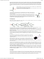
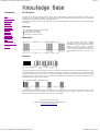
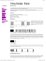
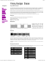
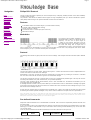
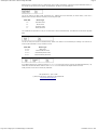
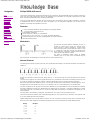
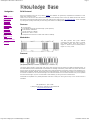
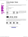
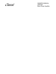
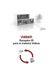
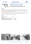
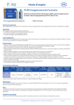
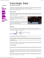
SB-Projects: IR remote control Navigation Home Knowledge Base IR RC Theory ITT Protocol JVC Protocol NEC Protocol Nokia NRC17 Sharp Protocol Sony SIRC Philips RC-5 Philips RC-6 Philips RC-MM Philips RECS80 RCA Protocol X-Sat Other Protocols Universal Controllers Page 1 IR Remote Control Theory The cheapest way to remotely control a device within a visible range is via Infra-Red light. Almost all audio and video equipment can be controlled this way nowadays. Due to this wide spread use the required components are quite cheap, thus making it ideal for us hobbyists to use IR control for our own projects. This part of my knowledge base will explain the theory of operation of IR remote control, and some of the protocols that are in use in consumer electronics. Infra-Red Light Infra-Red actually is normal light with a particular colour. We humans can't see this colour because its wave length of 950nm is below the visible spectrum. That's one of the reasons why IR is chosen for remote control purposes, we want to use it but we're not interested in seeing it. Another reason is because IR LEDs are quite easy to make, and therefore can be very cheap. Although we humans can't see the Infra-Red light emitted from a remote control doesn't mean we can't make it visible. A video camera or digital photo camera can "see" the Infra-Red light as you can see in this picture. If you own a web cam you're in luck, point your remote to it, press any button and you'll see the LED flicker. IR Control Unfortunately for us there are many more sources of Infra-Red light. The sun is the brightest source of all, but there are many others, like: light bulbs, candles, central heating system, and even our body radiates Infra-Red light. In fact everything that radiates heat, also radiates Infra-Red light. Therefore we have to take some precautions to guarantee that our IR message gets across to the receiver without errors. Modulation Modulation is the answer to make our signal stand out above the noise. With modulation we make the IR light source blink in a particular frequency. The IR receiver will be tuned to that frequency, so it can ignore everything else. You can think of this blinking as attracting the receiver's attention. We humans also notice the blinking of yellow lights at construction sites instantly, even in bright daylight. In the picture above you can see a modulated signal driving the IR LED of the transmitter on the left side. The detected signal is coming out of the receiver at the other side. In serial communication we usually speak of 'marks' and 'spaces'. The 'space' is the default signal, which is the off state in the transmitter case. No light is emitted during the 'space' state. During the 'mark' state of the signal the IR light is pulsed on and off at a particular frequency. Frequencies between 30kHz and 60kHz are commonly used in consumer electronics. At the receiver side a 'space' is represented by a high level of the receiver's output. A 'mark' is then automatically represented by a low level. Please note that the 'marks' and 'spaces' are not the 1-s and 0-s we want to transmit. The real relationship between the 'marks' and 'spaces' and the 1-s and 0-s depends on the protocol that's being used. More information about that can be found on the pages that describe the protocols. The Transmitter The transmitter usually is a battery powered handset. It should consume as little power as possible, and the IR signal should also be as strong as possible to achieve an acceptable control distance. Preferably it should be shock proof as well. Many chips are designed to be used as IR transmitters. The older chips were dedicated to only one of the many protocols that were invented. Nowadays very low power microcontrollers are used in IR transmitters for the simple reason that they are more flexible in their use. When no button is pressed they are in a very low power sleep mode, in which hardly any current is consumed. The processor wakes up to transmit the appropriate IR command only when a key is pressed. Quartz crystals are seldom used in such handsets. They are very fragile and tend to break easily when the handset is dropped. Ceramic resonators are much more suitable here, because they can withstand larger physical shocks. The fact that they are a little less accurate is not important. http://www.sbprojects.com/knowledge/ir/ir.htm 3/30/2009 8:58:27 AM SB-Projects: IR remote control Page 2 The current through the LED (or LEDs) can vary from 100mA to well over 1A! In order to get an acceptable control distance the LED currents have to be as high as possible. A trade-off should be made between LED parameters, battery lifetime and maximum control distance. LED currents can be that high because the pulses driving the LEDs are very short. Average power dissipation of the LED should not exceed the maximum value though. You should also see to it that the maximum peek current for the LED is not exceeded. All these parameters can be found in the LED's data sheet. A simple transistor circuit can be used to drive the LED. A transistor with a suitable HFE and switching speed should be selected for this purpose. The resistor values can simply be calculated using Ohm's law. Remember that the nominal voltage drop over an IR LED is approximately 1.1V. The normal driver, described above, has one disadvantage. As the battery voltage drops, the current through the LED will decrease as well. This will result in a shorter control distance that can be covered. An emitter follower circuit can avoid this. The 2 diodes in series will limit the pulses on the base of the transistor to 1.2V. The base-emitter voltage of the transistor subtracts 0.6V from that, resulting in a constant amplitude of 0.6V at the emitter. This constant amplitude across a constant resistor results in current pulses of a constant magnitude. Calculating the current through the LED is simply applying Ohm's law again. The Receiver Many different receiver circuits exist on the market. The most important selection criteria are the modulation frequency used and the availability in you region. In the picture above you can see a typical block diagram of such an IR receiver. Don't be alarmed if you don't understand this part of the description, for everything is built into one single electronic component. The received IR signal is picked up by the IR detection diode on the left side of the diagram. This signal is amplified and limited by the first 2 stages. The limiter acts as an AGC circuit to get a constant pulse level, regardless of the distance to the handset. As you can see only the AC signal is sent to the Band Pass Filter. The Band Pass Filter is tuned to the modulation frequency of the handset unit. Common frequencies range from 30kHz to 60kHz in consumer electronics. The next stages are a detector, integrator and comparator. The purpose of these three blocks is to detect the presence of the modulation frequency. If this modulation frequency is present the output of the comparator will be pulled low. As I said before, all these blocks are integrated into a single electronic component. There are many different manufacturers of these components on the market. And most devices are available in several versions each of which are tuned to a particular modulation frequency. Please note that the amplifier is set to a very high gain. Therefore the system tends to start oscillating very easily. Placing a large capacitor of at least 22µF close to the receiver's power connections is mandatory to decouple the power lines. Some data sheets recommend a resistor of 330 Ohms in series with the power supply to further decouple the power supply from the rest of the circuit. There are several manufacturers of IR receivers on the market. Siemens, Vishay and Telefunken are the main suppliers here in Europe. Siemens has its SFH506-xx series, where xx denotes the modulation frequency of 30, 33, 36, 38, 40 or 56kHz. Telefunken had its TFMS5xx0 and TK18xx series, where xx again indicates the modulation frequency the device is tuned to. It appears that these parts have now become obsolete. They are replaced by the Vishay TSOP12xx, TSOP48xx and TSOP62xx product series. Sharp, Xiamen Hualian and Japanese Electric are 3 Asian IR receiver producing companies. Sharp has devices with very cryptic ID names, like: GP1UD26xK, GP1UD27xK and GP1UD28xK, where x is related to the modulation frequency. Hualian has it's HRMxx00 series, like the HRM3700 and HRM3800. Japanese Electric has a series of devices that don't include the modulation frequency in the part's ID. The PIC-12042LM is tuned to 36.7kHz, and the PIC12043LM is tuned to 37.9kHz. The End? This concludes the theory of operation for IR remote control systems intended for use in consumer electronics. I realize that other ways exist to implement IR control, but I will limit myself to the description above. One of the issues not covered here is security. Security is of no importance if I want to control my VCR or TV set. But when it comes to opening doors or cars it literally becomes a 'key' feature! Maybe I will cover this issue later, but not for now. http://www.sbprojects.com/knowledge/ir/ir.htm 3/30/2009 8:58:27 AM SB-Projects: IR remote control Page 3 I also realize that my small list of manufacturers is far from being complete. It is hardly possible to list every manufacturer here. You can send me an e-mail if you have details about other protocols that you feel should be added to my pages. This page only described the basic theory of operation of IR remote control. It did not describe the protocols that are involved in communication between transmitter and receiver. Many protocols are designed by different manufacturers. You can find the protocols of some manufacturers in the link section at the top of this page. Last Updated: 23 - April - 2008 © 2001, San Bergmans, Oisterwijk, The Netherlands http://www.sbprojects.com http://www.sbprojects.com/knowledge/ir/ir.htm 3/30/2009 8:58:27 AM SB-Projects: IR remote control: ITT protocol Navigation Home Knowledge Base IR RC Theory ITT Protocol JVC Protocol NEC Protocol Nokia NRC17 Sharp Protocol Sony SIRC Philips RC-5 Philips RC-6 Philips RC-MM Philips RECS80 RCA Protocol X-Sat Other Protocols Universal Controllers Page 1 ITT Protocol The ITT IR protocol is a very old one. It differs from other protocols in that it does not use a modulated carrier frequency to send the IR messages. A single command is transmitted by a total of 14 pulses with a width of 10µs each. The command is encoded by varying the distance between the pulses. This protocol used to be very reliable and consumes very little power ensuring long battery life. One big disadvantage of this old protocol is that it sometimes triggers false commands, for instance when you put a laptop computer with an active IRDA port close to the IR receiver. Many consumer electronics brands used this protocol in Europe. Among them were: ITT, Greatz, Schaub-Lorenz, Finlux, Luxor, Salora, Oceanic and later also Nokia, to name but a few. Features Only 14 very short IR pulses per message Pulse distance encoding Long battery life 4 bit address, 6 bit command length Self calibrating timing, allowing only simple RC oscillator in the transmitter Fast communication, a message takes from 1.7ms to 2.7ms to transmit Manufacturer Intermetall, now Micronas IR Control Protocol An IR message is transmitted by sending 14 pulses. Each pulse is 10µs long. Three different time intervals between the pulses are used to get the message across: 100µs for a logic 0, 200µs for a logic 1 and 300µs for the lead-in and lead-out. The preliminary pulse is used by the receiver to set the gain of the amplifier. Then follows a lead-in interval of 300µs, after which the starting pulse is given. The first bit sent is always logic 0, which has an interval duration of 100µs. This start bit can be used to calibrate the timing of the receiver. After the start bit follow 4 bits (MSB first) that represent the address of the message. After that a total of 6 bits (MSB first) for the command are transmitted. A trailing pulse should follow this command word. Finally another 300µs interval follows before the very last pulse is given, functioning as a lead-out. There are a few things the receiving software can check to verify the validity of the received message. The lead-out interval should be 3 times longer than the start bit time, which has a duration of 100µs. Bit times should not be off by more than ±20% of the start bit length for logic 0s, or 2x the start bit length for logic 1s. Don't keep waiting for pulses after 360µs after the last received pulse. It's very likely that the transmission is interrupted or no transmission took place at all if you have to wait longer than that. The preliminary pulse serves only AGC purposes and may be ignored by the receiving software. Decoding of the message should start at the Start pulse. Address and Command A control message is divided into two groups, an address of 4 bits and a command of 6 bits. By convention the addresses range from 1 to 16, and commands range from 1 to 64. Before the address and command are sent, 1 is subtracted from both values to get them in the range 0 to 15 and 0 to 63. Addresses are used in pairs. A pair of addresses is a value of 1 to 8 (0 to 7 actually), and its inverted counter part 16 to 9 (15 to 8 actually). The lower value address is transmitted the first time a key is pressed. The address value of all subsequent messages will be the inverted value of this first address until the key is released. This enables the receiver to interpret repeat codes properly. Messages are repeated every 130ms as long as the key remains pressed. The Transmitter Intermetall has developed a few transmitter ICs for use in handsets. Later microcontrollers were used to facilitate the combination of TV, VCR and SAT remote control in one handset. http://www.sbprojects.com/knowledge/ir/itt.htm 3/30/2009 9:01:29 AM SB-Projects: IR remote control: ITT protocol Page 2 The SAA1250 was the first IR controller IC to be released. It can be set to generate 3 different address pairs. A fourth option is transmitting any of the 16 addresses. That option is rarely used, for it requires a manual setup procedure every time the power is lost. The second generation of IR controller ICs are the IRT1250 and IRT1260. These chips are identical in operation and differ only in the operating voltage. The IRT1250 is intended for 9V operation, whilst the IRT1260 is designed for 3V. The footprint of the IRT12x0 is the same as that of the SAA1250. The devices differ in addressing capability and current drive capacity for the output stage. Two address pins are available to set the address pair used. A1 A2 Addresses H H 1 & 16 L H 3 & 14 H L 7 & 10 L L 4 & 13 Addresses 1 and 16 are always used to control TV sets. Other address pairs are not always uniquely linked to a particular equipment family. Receiver The ITT protocol makes no use of a modulated carrier, so the previously mentioned IR receivers won't work for this protocol. Intermetall has created the TBA2800 for use with this protocol. It is a highly sensitive IR detection circuit and should be shielded completely inside a metal box that is connected to ground, leaving only a small hole just in front of the IR diode. There is actually not much more to be told about this IC. Just connect it as shown in the diagram and it should work. You can chose between a normal high going output, and an inverted low going output. It depends on the rest of your circuitry which one you should use. In case of excessive interference you could reduce the sensitivity a little by grounding pin 6 via a 10kΩ resistor. Pre-defined Commands Some of the 64 possible commands are predefined. But unfortunately the definition of the commands is not as clear as with RC-5. You can find most of the pre-defined commands for TV purposes in the following table. TV commands use the address pair 1 and 16. Command 1 2 3 4 5 6 7 8 9 10 11 12 13 14 15 16 17 18 19 20 21 Function Stand-by TV Ideal Up Down Mute P+ PLeft / Bilingual Right Last 1 2 3 4 5 http://www.sbprojects.com/knowledge/ir/itt.htm Command 33 34 35 36 37 38 39 40 41 42 43 44 45 46 47 48 49 50 51 52 53 Function -/-Audio Video Clock Brightness + Brightness Saturation + Saturation Volume + Volume S Red / Memory Green Contrast 3/30/2009 9:01:29 AM SB-Projects: IR remote control: ITT protocol Page 3 22 23 6 7 24 25 8 9 26 27 28 0 55 Zoom 29 30 X 31 32 Info Yellow / Saturation 56 57 58 59 Menu 60 61 62 Auto Text OK / Prog 63 64 C Last Updated: 23 - April - 2008 © 2001, San Bergmans, Oisterwijk, The Netherlands http://www.sbprojects.com http://www.sbprojects.com/knowledge/ir/itt.htm 3/30/2009 9:01:29 AM SB-Projects: IR remote control: JVC protocol Navigation Home Knowledge Base IR RC Theory ITT Protocol JVC Protocol NEC Protocol Nokia NRC17 Sharp Protocol Sony SIRC Philips RC-5 Philips RC-6 Philips RC-MM Philips RECS80 RCA Protocol X-Sat Other Protocols Page 1 JVC Protocol JVC also has its own IR protocol, although I have seen several different protocols being used in a diversity of JVC equipment. This is probably the case for equipment which JVC haven't made themselves. Most genuine JVC equipment is controlled by the protocol described on this page though. All information about this protocol was collected using a JVC PTU94023B service remote control and a digital storage oscilloscope. Features 8 bit address and 8 bit command length Pulse distance modulation Carrier frequency of 38kHz Bit time of 1.05ms or 2.10ms Modulation The JVC protocol uses pulse distance encoding of the bits. Each pulse is a 526µs long 38kHz carrier burst (about 20 cycles). A logical "1" takes 2.10ms to transmit (equivalent of 80 cycles), while a logical "0" is only 1.05ms (equivalent of 40 cycles). The recommended carrier duty cycle is 1/4 or 1/3. Universal Controllers IR Control Protocol The picture above shows a typical pulse train of the JVC protocol. With this protocol the LSB is transmitted first. In this case Address $59 and Command $35 is transmitted. A message is started by a 8.4ms AGC burst (equivalent of 320 cycles), which was used to set the gain of the earlier IR receivers. This AGC burst is then followed by a 4.2ms space (equivalent of 160 cycles), which is then followed by the Address and Command. The total transmission time is variable because the bit times are variable. An IR command is transmitted every 50 to 60ms for as long as the key on the remote is held down. Only the first command is preceded by the 8.4ms pre-pulse and its accompanying 2.4ms space. This way the receiver can determine whether a key is pressed for the first time or is held down. Last Updated: 23 - April - 2008 © 2004, San Bergmans, Oisterwijk, The Netherlands http://www.sbprojects.com http://www.sbprojects.com/knowledge/ir/jvc.htm 3/30/2009 9:02:34 AM SB-Projects: IR remote control: NEC protocol Navigation Home Knowledge Base IR RC Theory ITT Protocol JVC Protocol NEC Protocol Nokia NRC17 Sharp Protocol Sony SIRC Philips RC-5 Philips RC-6 Philips RC-MM Philips RECS80 RCA Protocol X-Sat Other Protocols Page 1 NEC Protocol To my knowledge the protocol I describe here was developed by NEC. I've seen very similar protocol descriptions on the internet, and there the protocol is called Japanese Format. I do admit that I don't know exactly who developed it. What I do know is that it is used in my late VCR produced by Sanyo and was marketed under the name of Fisher. NEC manufactured the remote control IC. This description was taken from the VCR's service manual. Those were the days, when service manuals were fulled with useful information! Features 8 bit address and 8 bit command length Address and command are transmitted twice for reliability Pulse distance modulation Carrier frequency of 38kHz Bit time of 1.125ms or 2.25ms Modulation Universal Controllers The NEC protocol uses pulse distance encoding of the bits. Each pulse is a 560µs long 38kHz carrier burst (about 21 cycles). A logical "1" takes 2.25ms to transmit, while a logical "0" is only half of that, being 1.125ms. The recommended carrier dutycycle is 1/4 or 1/3. IR Control Protocol The picture above shows a typical pulse train of the NEC protocol. With this protocol the LSB is transmitted first. In this case Address $59 and Command $16 is transmitted. A message is started by a 9ms AGC burst, which was used to set the gain of the earlier IR receivers. This AGC burst is then followed by a 4.5ms space, which is then followed by the Address and Command. Address and Command are transmitted twice. The second time all bits are inverted and can be used for verification of the received message. The total transmission time is constant because every bit is repeated with its inverted length. If you're not interested in this reliability you can ignore the inverted values, or you can expand the Address and Command to 16 bits each! A command is transmitted only once, even when the key on the remote control remains pressed. Every 110ms a repeat code is transmitted for as long as the key remains down. This repeat code is simply a 9ms AGC pulse followed by a 2.25ms space and a 560µs burst. Extended NEC protocol The NEC protocol is so widely used that soon all possible addresses were used up. By sacrificing the address redundancy the address range was extended from 256 possible values to approximately 65000 different values. This way the address range was extended from 8 bits to 16 bits without changing any other property of the protocol. The command redundancy is still preserved. Therefore each address can still handle 256 different commands. http://www.sbprojects.com/knowledge/ir/nec.htm 3/30/2009 9:03:10 AM SB-Projects: IR remote control: NEC protocol Page 2 Keep in mind that 256 address values of the extended protocol are invalid because they are in fact normal NEC protocol addresses. Whenever the low byte is the exact inverse of the high byte it is not a valid extended address. Example Commands The table below lists the messages sent by the remote control of my late Fisher 530 VCR (it served us well during its 20 years long life). NEC Message Key Function $68-$00 Play $68-$01 Rec $68-$02 Audio Dub $68-$03 Frame Adv $68-$04 Slow $68-$05 Quick $68-$06 Cue $68-$07 Review $68-$08 FF $68-$09 Rew $68-$0A Stop $68-$0B Pause/Still $68-$0C Up key $68-$1E Down key Last Updated: 23 - April - 2008 © 2001, San Bergmans, Oisterwijk, The Netherlands http://www.sbprojects.com http://www.sbprojects.com/knowledge/ir/nec.htm 3/30/2009 9:03:10 AM SB-Projects: IR remote control: Nokia NRC17 Navigation Home Knowledge Base IR RC Theory ITT Protocol JVC Protocol NEC Protocol Nokia NRC17 Sharp Protocol Sony SIRC Philips RC-5 Philips RC-6 Philips RC-MM Philips RECS80 RCA Protocol X-Sat Other Protocols Page 1 Nokia NRC17 Protocol The Nokia Remote Control protocol uses 17 bits to transmit the IR commands, which immediately explains the name of this protocol. The protocol was designed for Nokia consumer electronics. It was used during the last few years in which Nokia produced TV sets and VCRs. Also the sister brands like Finlux and Salora used this protocol. Nowadays the protocol is mainly used in Nokia satellite receivers and set-top boxes. Features 8 bit command, 4 bit address and 4 bit sub-code length Bi-phase coding Carrier frequency of 38kHz Constant bit time of 1ms Battery empty indication possible Manufacturer Nokia CE Modulation Universal Controllers The protocol uses bi-phase (or so-called NRZ - Non Return to Zero) modulation of a 38kHz IR carrier frequency. All bits are of equal length of 1ms in this protocol, with half of the bit time filled with a burst of the 38kHz carrier and the other half being idle. A logical one is represented by a burst in the first half of the bit time. A logical zero is represented by a burst in the second half IR Control of the bit time. The pulse/pause ratio of the 38kHz carrier frequency is 1/4 which helps to reduce power consumption. Protocol The drawing below shows a typical pulse train of an NRC17 message. This example transmits command $5C to address $6 sub-code $1. The first pulse is called the pre-pulse, and is made up of a 500µs burst followed by a 2.5ms pause, giving a total of 3 bit times. Then the Start bit is transmitted, which is always a logic "1". This pulse can be used to calibrate the bit time on the receiver side, because the burst time is exactly half a bit time. The next 8 bits represent the IR command, which is sent with LSB first. The command is followed by a 4 bit device address. Finally a 4 bit sub-code is transmitted, which can be seen as an extension to the address bits. A message consists of a 3ms pre-pulse and 17 bits of 1ms each. This adds up to a total of 20ms per message. Every time a key is pressed on the remote control a start message is transmitted containing a command of $FE and address/sub-code of $FF. The actual message is sent 40ms later, and is repeated every 100ms for as long as the key on the remote control remains down. When the key is released a stop message will complete the sequence. The stop message also uses the command $FE and address/sub-code $FF. Every sequence can be treated as one single sequence at the receiver's end because of the start and stop messages. Accidental key bounces are effectively eliminated by this procedure. The receiver may decide to honour the repeated messages or not. E.g. cursor movements may repeat for as long as the key is pressed. Numerical inputs better don't allow auto repeat. Low Battery Indication The NRC17 protocol provides in a way for the remote control to tell the receiver that the battery capacity is getting low. The receiver may display a message on the TV screen informing the user that the remote control's batteries have to be replaced. http://www.sbprojects.com/knowledge/ir/nrc17.htm 3/30/2009 9:04:21 AM SB-Projects: IR remote control: Nokia NRC17 Page 2 to be replaced. The pre-pulse normally is 3ms long. When the battery power is low this pre-pulse will become 4ms long. In practice only the pre-pulse of the start and stop messages are made longer this way. Pre-defined Commands I only have a small list of pre-defined commands. The protocol description that I have doesn't specify more. Please note that the address of the SAT commands applies to Analog receivers only. NRC17 Command CTV Address: $A Sub-code: $4 SAT Address: $C Sub-code: $0 $00 0 / Extern 0 / Extern $01 1 1 $02 2 2 $03 3 3 $04 4 4 $05 5 5 $06 6 6 $07 7 7 $08 8 8 $09 9 9 $0C Stand-by Stand-by $0E Up key Up key $0F Down key Down key $28 Mute Mute $29 Ideal Reveal Alternate $2A Alternate $2D Index Index $2E Right key Right key $2F Left key Left key $33 Text Text $35 Stop Stop $38 Size Size $3C Red (OK) Red $3D Green (Sound) Green $3E Yellow (Picture) Yellow $3F Blue (Extra) $70 TV TV/SAT Last Updated: 23 - April - 2008 © 2001, San Bergmans, Oisterwijk, The Netherlands http://www.sbprojects.com http://www.sbprojects.com/knowledge/ir/nrc17.htm 3/30/2009 9:04:21 AM SB-Projects: IR remote control: Sharp protocol Navigation Page 1 Sharp Protocol Home Knowledge Base I only have little information on this protocol. It is used in VCRs that are produced by Sharp, that is why I gave it the name Sharp protocol. IR RC Theory ITT Protocol JVC Protocol NEC Protocol Nokia NRC17 Sharp Protocol Sony SIRC Philips RC-5 Philips RC-6 Philips RC-MM Philips RECS80 RCA Protocol X-Sat Other Protocols Features 8 bit command, 5 bit address length Pulse distance modulation Carrier frequency of 38kHz Bit time of 1ms or 2ms Modulation The Sharp protocol uses a pulse distance encoding of the bits. Each pulse is a 320µs long 38kHz carrier burst (about 12 cycles). A logical "1" takes 2ms to transmit, while a logical "0" is only 1ms. The recommended carrier duty-cycle is 1/4 or 1/3. Universal Controllers IR Control Protocol In the picture above you see a typical pulse train sending the command $11 and address $03. The Address is sent first and consists of 5 bits. Next comes the 8 bit command. In both cases the LSB of the data is sent first. I don't exactly know the purpose of the Expansion and Check bits that follow the command. Both bits were fixed in the example that I had at hand. I can only guess that the Check bit is used to find out whether we are receiving a normal or inverted message. One complete command sequence consist of 2 messages. The first transmission is exactly as described above. The second transmission follows the first one after a delay of 40ms, and basically contains the same information. The only difference is that all bits, except those from the address field, are inverted. This way the receiver can verify if the received message is reliable or not. Last Updated: 23 - April - 2008 © 2001, San Bergmans, Oisterwijk, The Netherlands http://www.sbprojects.com http://www.sbprojects.com/knowledge/ir/sharp.htm 3/30/2009 9:04:51 AM SB-Projects: IR remote control: SIRC protocol Navigation Home Knowledge Base IR RC Theory ITT Protocol JVC Protocol NEC Protocol Nokia NRC17 Sharp Protocol Sony SIRC Philips RC-5 Philips RC-6 Philips RC-MM Philips RECS80 RCA Protocol X-Sat Other Protocols Universal Controllers IR Control Page 1 Sony SIRC Protocol I've collected and combined some information found on the internet about the Sony SIRC protocol. I must admit that I have never worked with this particular protocol, so I could not verify that all information is valid for all situations. It appears that 3 versions of the protocol exist: 12-bit (described on this page), 15-bit and 20-bit versions. I can only assume that the 15-bit and 20-bit versions differ in the number of transmitted bits per command sequence. Please note that a lot of confusing documentation about the SIRC protocol exists on the internet. At first I contributed to the confusion by assuming the correctness of the source documents I found myself, until someone with some SIRC experience informed me about my errors. I double checked his story with a universal remote control and a digital storage oscilloscope, and found that the bit and word order I documented were indeed wrong. The protocol information on this page is according to my own measurements and should be correct now. Features 12-bit, 15-bit and 20-bit versions of the protocol exist (12-bit described here) 5-bit address and 7-bit command length (12-bit protocol) Pulse width modulation Carrier frequency of 40kHz Bit time of 1.2ms or 0.6ms Modulation The SIRC protocol uses a pulse width encoding of the bits. The pulse representing a logical "1" is a 1.2ms long burst of the 40kHz carrier, while the burst width for a logical "0" is 0.6ms long. All bursts are separated by a 0.6ms long space interval. The recommended carrier duty-cycle is 1/4 or 1/3. Protocol The picture above shows a typical pulse train of the SIRC protocol. With this protocol the LSB is transmitted first. The start burst is always 2.4ms wide, followed by a standard space of 0.6ms. Apart from signalling the start of a SIRC message this start burst is also used to adjust the gain of the IR receiver. Then the 7-bit Command is transmitted, followed by the 5-bit Device address. In this case Address 1 and Command 19 is transmitted. Commands are repeated every 45ms(measured from start to start) for as long as the key on the remote control is held down. Example Commands The table below lists some messages sent by Sony remote controls in the 12-bit protocol. This list is by no means meant to be complete, as the assignment of functions is probably quite dynamic. Address 1 2 3 6 12 16 17 18 Device TV VCR 1 VCR 2 Laser Disc Unit Surround Sound Cassette deck / Tuner CD Player Equalizer http://www.sbprojects.com/knowledge/ir/sirc.htm Command 0 1 2 3 4 5 6 7 8 9 16 17 18 Function Digit key 1 Digit key 2 Digit key 3 Digit key 4 Digit key 5 Digit key 6 Digit key 7 Digit key 8 Digit key 9 Digit key 0 Channel + Channel Volume + 3/30/2009 9:05:48 AM SB-Projects: IR remote control: SIRC protocol Page 2 19 20 Volume Mute 21 22 Power Reset 23 24 25 Audio Mode Contrast + Contrast - 26 27 Colour + Colour - 30 31 38 Brightness + Brightness Balance Left 39 Balance Right 47 Standby Last Updated: 23 - April - 2008 © 2003, San Bergmans, Oisterwijk, The Netherlands http://www.sbprojects.com http://www.sbprojects.com/knowledge/ir/sirc.htm 3/30/2009 9:05:48 AM SB-Projects: IR remote control: Philips RC-5 Navigation Home Knowledge Base IR RC Theory ITT Protocol JVC Protocol NEC Protocol Nokia NRC17 Sharp Protocol Sony SIRC Philips RC-5 Philips RC-6 Philips RC-MM Philips RECS80 RCA Protocol X-Sat Other Protocols Universal Controllers IR Control Page 1 Philips RC-5 Protocol The RC-5 code from Philips is possibly the most used protocol by hobbyists, probably because of the wide availability of cheap remote controls. The protocol is well defined for different device types ensuring compatibility with your whole entertainment system. Lately Philips started using a new protocol called RC-6 which has more features. Features 5 bit address and 6 bit command length (7 command bits for RC5X) Bi-phase coding (aka Manchester coding) Carrier frequency of 36kHz Constant bit time of 1.778ms (64 cycles of 36 kHz) Manufacturer Philips Modulation The protocol uses bi-phase modulation (or socalled Manchester coding) of a 36kHz IR carrier frequency. All bits are of equal length of 1.778ms in this protocol, with half of the bit time filled with a burst of the 36kHz carrier and the other half being idle. A logical zero is represented by a burst in the first half of the bit time. A logical one is represented by a burst in the second half of the bit time. The pulse/pause ratio of the 36kHz carrier frequency is 1/3 or 1/4 which reduces power consumption. Protocol The drawing below shows a typical pulse train of an RC-5 message. This example transmits command $35 to address $05. The first two pulses are the start pulses, and are both logical "1". Please note that half a bit time is elapsed before the receiver will notice the real start of the message. Extended RC-5 uses only one start bit. Bit S2 is transformed to command bit 6, providing for a total of 7 command bits. The value of S2 must be inverted to get the 7th command bit though! The 3rd bit is a toggle bit. This bit is inverted every time a key is released and pressed again. This way the receiver can distinguish between a key that remains down, or is pressed repeatedly. The next 5 bits represent the IR device address, which is sent with MSB first. The address is followed by a 6 bit command, again sent with MSB first. A message consists of a total of 14 bits, which adds up to a total duration of 25 ms. Sometimes a message may appear to be shorter because the first half of the start bit S1 remains idle. And if the last bit of the message is a logic "0" the last half bit of the message is idle too. As long as a key remains down the message will be repeated every 114ms. The toggle bit will retain the same logical level during all of these repeated messages. It is up to the receiver software to interpret this auto repeat feature. PS: I had rather a big error on this page for quite some time. For some mysterious reason the LSB and MSB of the address and command were reversed. I can recall correcting this error before, but somehow an old version of the description must have sneaked its way up to the internet again. Pre-defined Commands Philips has created a beautiful list of "standardized" commands. This ensures the compatibility between devices from the same brand. A very nice feature, often to be missed with other brands, is the fact that most devices are available twice in the table allowing you to have 2 VCRs stacked on top of each other without having trouble addressing only one of them with your remote control. I can only show a limited list of standard commands, for this list is about all I know right now. RC-5 Address http://www.sbprojects.com/knowledge/ir/rc5.htm Device RC-5 Command TV Command VCR Command 3/30/2009 9:06:25 AM SB-Projects: IR remote control: Philips RC-5 Page 2 $00 - 0 $01 - 1 TV1 TV2 $00 - 0 $01 - 1 0 1 0 1 $02 - 2 $03 - 3 Teletext Video $04 - 4 $05 - 5 $06 - 6 LV1 VCR1 VCR2 $02 - 2 $03 - 3 $04 - 4 2 3 4 2 3 4 $05 - 5 $06 - 6 5 6 5 6 $07 - 7 $08 - 8 Experimental Sat1 $07 - 7 7 7 $09 - 9 $0A - 10 $0B - 11 Camera Sat2 $08 - 8 $09 - 9 8 9 8 9 -/-Standby Mute -/-Standby $0C - 12 CDV $0A - 10 $0C - 12 $0D - 13 $0D - 13 Camcorder $10 - 16 Volume + $11 - 17 $12 - 18 $13 - 19 Volume Brightness + Brightness - $0E - 14 $0F - 15 $10 - 16 $11 - 17 Pre-amp Tuner $20 - 32 Program + Program + $12 - 18 $13 - 19 Recorder1 Pre-amp $21 - 33 $32 - 50 Program - Program Fast Rewind $14 - 20 $15 - 21 CD Player Phono $34 - 52 $35 - 53 Play $16 - 22 $17 - 23 $18 - 24 SatA Recorder2 $36 - 54 $37 - 55 Stop Recording Fast Forward $19 - 25 $1A $1B $1C $1D $1E - 26 - 27 - 28 - 29 - 30 $1F - 31 CDR Lighting Lighting Phone Last Updated: 23 - April - 2008 © 2001, San Bergmans, Oisterwijk, The Netherlands http://www.sbprojects.com http://www.sbprojects.com/knowledge/ir/rc5.htm 3/30/2009 9:06:25 AM SB-Projects: IR remote control: Philips RC-6 Navigation Home Knowledge Base IR RC Theory ITT Protocol JVC Protocol NEC Protocol Nokia NRC17 Sharp Protocol Sony SIRC Philips RC-5 Philips RC-6 Philips RC-MM Philips RECS80 RCA Protocol X-Sat Other Protocols Universal Controllers IR Control Page 1 Philips RC-6 Protocol RC-6 is, as may be expected, the successor of the RC-5 protocol. Like RC-5 the new RC-6 protocol was also defined by Philips. It is a very versatile and well defined protocol. Because of this versatility its original definition is many pages long. Here on my page I will only summarize the most important properties of this protocol. Features Different modes of operation, depending on the intended use Dedicated Philips modes and OEM modes Variable command length, depending on the operation mode Bi-phase coding (aka Manchester coding) Carrier frequency of 36kHz Manufacturer Philips Modulation RC-6 signals are modulated on a 36 kHz Infra Red carrier. The duty cycle of this carrier has to be between 25% and 50%. Data is modulated using Manchester coding. This means that each bit (or symbol) will have both a mark and space in the output signal. If the symbol is a "1" the first half of the bit time is a mark and the second half is a space. If the symbol is a "0" the first half of the bit time is a space and the second half is a mark. Please note that this is the opposite of the RC-5 protocol! The main timing unit is 1t, which is 16 times the carrier period (1/36k * 16 = 444µs). With RC-6 a total of 5 different symbols are defined: The leader pulse, which has a mark time of 6t (2.666ms) and a space time of 2t (0.889ms). This leader pulse is normally used to set the gain of the IR receiver unit. Normal bits, which have a mark time of 1t (0.444ms) and space time of 1t (0.444ms). A "0" and "1" are encoded by the position of the mark and space in the bit time. Trailer bits, which have a mark time of 2t (0.889ms) and a space time of 2t (0.889ms). Again a "0" and "1" are encoded by the position of the mark and space in the bit time. The leader and trailer symbols are only used in the header field of the messages, which will be explained in more detail below. RC-6 Mode 0 I can only describe operation mode 0 because I have never actually seen other modes in use than the one my Philips TV understands. The way I understand it the other modes can vary extremely from mode 0. Mode 0 is a dedicated Philips Consumer Electronics mode. It allows control of up to 256 independent devices, with a total of 256 commands per device. The command is a concatenation of different information. I will cover these different components from left to right. Header field http://www.sbprojects.com/knowledge/ir/rc6.htm 3/30/2009 9:06:52 AM SB-Projects: IR remote control: Philips RC-6 Page 2 Header field The Header field consists of 3 different components. First the leader symbol LS is transmitted. Its purpose is to adjust the gain of the IR receiving unit. This leader symbol is followed by a start bit SB which always has the value "1". Its purpose is to calibrate the receiver's timing. The mode bits mb2 ... mb0 determine the mode, which is 0 in this case, thus all three bits will be "0". Finally the header is terminated by the trailer bit TR. Please note that the bit time of this symbol is twice as long as normal bits! This bit also serves as the traditional toggle bit, which will be inverted whenever a key is released. This allows the receiver to distinguish between a new key or a repeated key. Control Field This field holds 8 bits which are used as address byte. This means that a total of 256 different devices can be controlled using mode 0 of RC-6. The msb is transmitted first. Information Field The information field holds 8 bits which are used as command byte. This means that each device can have up to 256 different commands. The msb is transmitted first. Signal Free Time The Signal Free time is a period in which no data may be transmitted (by any device). It is important for the receiver to detect the signal free time at the end of a message to avoid incorrect reception. The signal free time is set to 6t, which is 2.666ms. Last Updated: 23 - April - 2008 © 2005, San Bergmans, Oisterwijk, The Netherlands http://www.sbprojects.com http://www.sbprojects.com/knowledge/ir/rc6.htm 3/30/2009 9:06:52 AM SB-Projects: IR remote control: Philips RC-MM Navigation Home Knowledge Base IR RC Theory ITT Protocol JVC Protocol NEC Protocol Nokia NRC17 Sharp Protocol Sony SIRC Philips RC-5 Philips RC-6 Philips RC-MM Philips RECS80 RCA Protocol X-Sat Other Protocols Page 1 Philips RC-MM Protocol RC-MM was defined by Philips to be a multi-media IR protocol to be used in wireless keyboards, mice and game pads. For these purposes the commands had to be short and have low power requirements. Whether the protocol is actually used for these purposes today is unknown to me. What I do know is that some Nokia digital satellite receivers use the protocol (9800 series). Features 12 bits or 24 bits per message Pulse position coding, sending 2 bits per IR pulse Carrier frequency of 36kHz Message time ranges from 3.5 to 6.5 ms, depending on data content Repetition time 28 ms (36 messages per second) Manufacturer Philips Transmission timing Universal Controllers IR Control In this diagram you see the most important transmission times. The message time is the total time of a message, counting form the beginning of the first pulse until the end of the last pulse of the message. This time can be 3.5 to 6.5 ms, depending on the data content and protocol used. The signal free time is the time in which no signal may be sent to avoid confusion with foreign protocols on the receiver's side. Philips recommends 1 ms for normal use, or 3.36 ms when used together with RC-5 and RC-6 signals. Since you can never tell whether a user has other remote controls in use together with an RC-MM controlled device I would recommend always to use a signal free time of 3.36 ms. The frame time is the sum of the message time and the signal free time, which can add up to just about 10 ms per message. Finally the repetition time is the recommended repetition time of 27.778 ms, which allows 36 messages per second. This is only a recommendation and is mainly introduced to allow other devices to send their commands during the dead times. No provision is made for data collisions between two or more remote controls! This means that there is no guarantee that the messages get across. Modulation With this protocol a 36 kHz carrier frequency is used to transmit the pulses. This helps to increase the noise immunity at the receiver side and at the same time it reduces power dissipated by the transmitter LED. The duty cycle of the pulses is 1:3 or 1:4. Each message is preceded by a header pulse with the duration of 416.7 µs (15 pulses of the carrier), followed by a space of 277.8 µs (10 periods of the carrier). This header is followed by 12 or 24 bits of data. By changing the distance between the pulses two bits of data are encoded per pulse. Below you find a table with the encoding times. Data Mark Space 00 166.7 µs (6 cycles) 277.8 µs (10 cycles) 01 166.7 µs (6 cycles) 444.4 µs (16 cycles) 10 166.7 µs (6 cycles) 611.1 µs (22 cycles) 11 166.7 µs (6 cycles) 777.8 µs (28 cycles) Protocol RCMM comes in 3 different flavours, called modes. Each mode is intended for a particular purpose and differs mainly in the number of bits which can be used by the application. All data is sent with MSB first. http://www.sbprojects.com/knowledge/ir/rcmm.htm 3/30/2009 9:07:19 AM SB-Projects: IR remote control: Philips RC-MM Page 2 RCMM comes in 3 different flavours, called modes. Each mode is intended for a particular purpose and differs mainly in the number of bits which can be used by the application. All data is sent with MSB first. The 12 bit mode is the basic mode, and allows for 2 address bits and 8 data bits per device family. There are 3 different device families defined: keyboard, mouse and game pad. Mode bits Device Type 00 Extended mode 01 Mouse mode 10 Keyboard mode 11 Game pad mode The 2 address bits provide for a way to use more than 1 device simultaneously. The data bits are the actual payload data. The 24 bit mode, also know as extended mode, allows more data to be transmitted per message. For instance for multi-lingual keyboards or a high resolution mouse. Mode bits Device Type 0000 OEM mode 0001 Extended Mouse mode 0010 Extended Keyboard mode 0011 Extended Game pad mode In the OEM mode the first 6 bits are always 0 0 0 0 1 1. The next 6 bits are the customer ID (OEM manufacturer). My observation showed that Nokia used the code 1 0 0 0 0 0 for their 9800 series digital satellite receivers. Finally the last 12 bits are the actual pay load data. Last Updated: 23 - April - 2008 © 2005, San Bergmans, Oisterwijk, The Netherlands http://www.sbprojects.com http://www.sbprojects.com/knowledge/ir/rcmm.htm 3/30/2009 9:07:19 AM SB-Projects: IR remote control: Philips RECS-80 Navigation Home Knowledge Base IR RC Theory ITT Protocol JVC Protocol NEC Protocol Nokia NRC17 Sharp Protocol Sony SIRC Philips RC-5 Philips RC-6 Philips RC-MM Philips RECS80 RCA Protocol X-Sat Other Protocols Page 1 Philips RECS-80 Protocol This protocol is designed by Philips and transmitters are produced by Philips (SAA3008) and ST (M3004). Personally I have never seen this protocol being used in real applications. All information on this page is derived from the data sheet of the Philips SAA3008 and the ST M3004 (10624.pdf). There are 2 small differences between the two competitor ICs. The Philips IC has two modes of operation, one which is compatible with the ST chip and one which can handle up to 20 sub-system addresses. The ST chip has the capability of switching the modulation carrier off. Features 7 or 20 sub-system addresses, 64 commands per sub-system address 1 or 2 toggle bits to avoid key bounce Pulse distance modulation Carrier frequency of 38kHz, or unmodulated Bit time logic "0" is 5.1ms, logic "1" is 7.6ms (@ 455kHz Oscillator) Command repetition rate 121.5ms (55296 periods of the main oscillator) Manufacturer Philips & ST Universal Controllers IR Control Modulation The protocol uses pulse distance modulation. A logic "0" consists of a mark with a length of 6 periods of the carrier frequency (158µs), followed by a space which makes the total pulse to pulse distance 5.06ms. A logic "1" consists of a mark with a length of 6 periods of the carrier frequency, followed by a space which makes the total pulse to pulse distance 7.59ms. The mark is modulated (38kHz carrier @ 455kHz oscillator) with a 1/3 duty cycle. The M3004 chip can also send marks unmodulated, but that would result in worse noise immunity. Normal Protocol The drawing below shows a typical pulse train of a normal RECS-80 message. This example transmits command 36 to address 4. Usually the first pulse is a reference pulse, with a value of "1". The receiver may use this bit to determine the exact bit length. The next bit is a toggle bit. Its value is toggled whenever a key is released, which results in a different code every time a new key is pressed. This allows the receiver to discriminate between new key presses and key repetitions. Only the ST chip M3004 can disable its carrier, in which case the REF pulse is interpreted as a second toggle bit. The 2bit toggle value is incremented every time a key is released. Thus only in this mode there is no real REF pulse. The next 3 pulses S2 to S0 represent the sub-system address bits, sent with MSB first. This would allow for 8 different sub-system addresses but both the SAA3008 and the M3004 can only generate 7 sub-system addresses in normal mode. Next come the 6 command bits F to A, also sent with MSB first allowing for 64 different commands per subsystem address. The pulse train is terminated by a last pulse, otherwise there is no way to know the duration of bit A. The entire command is repeated (with unchanged toggle bits) for as long as the key is held down. The repetition rate is 121.5ms (55296 periods of the oscillator). Address assignments are a bit odd with this protocol. You can not simply convert the binary value to a decimal value. Below you see a table explaining the relationship between the binary and decimal sub-system address values. Binary Decimal 111 1 000 2 001 3 010 4 011 5 100 6 http://www.sbprojects.com/knowledge/ir/recs80.htm 3/30/2009 9:07:41 AM SB-Projects: IR remote control: Philips RECS-80 Page 2 101 7 Extended Protocol If you need more than 7 sub-system addresses you can use the extended protocol which allows 13 additional subsystem addresses only if you use the SAA3008. The drawing below shows an extended message. This example transmits command 36 to address 10. The first two pulses are a special start sequence. The total duration of these pulses is equal to a normal "1" period. The next bit is a toggle bit. Its value is toggled whenever a key is released, which results in a different code every time a new key is pressed. This allows the receiver to discriminate between new key presses and key repetitions. The next 4 pulses S3 to S0 represent the sub-system address bits. This would allow for an additional 16 different subsystem addresses, although the SAA3008 can only generate 13 additional sub-system addresses in this mode. Next come the 6 command bits F to A, also sent with MSB first. The pulse train is terminated by a last pulse, otherwise there is no way to know the duration of bit A. The entire command is repeated (with unchanged toggle bits) for as long as the key is held down. The repetition rate is 121.5ms (55296 periods of the oscillator). Address assignments are a bit odd with this protocol. You can not simply convert the binary value to a decimal value. Below you see a table explaining the relationship between the binary and decimal sub-system address values. Binary Decimal 0000 8 1000 9 0100 10 1100 11 0001 12 1001 13 0101 14 1101 15 1010 16 0110 17 1110 18 0111 19 1111 20 Last Updated: 23 - April - 2008 © 2005, San Bergmans, Oisterwijk, The Netherlands http://www.sbprojects.com http://www.sbprojects.com/knowledge/ir/recs80.htm 3/30/2009 9:07:41 AM SB-Projects: IR remote control: RCA Navigation Home Knowledge Base IR RC Theory ITT Protocol JVC Protocol NEC Protocol Nokia NRC17 Sharp Protocol Sony SIRC Philips RC-5 Philips RC-6 Philips RC-MM Philips RECS80 RCA Protocol X-Sat Other Protocols Page 1 RCA Protocol Here's a contribution from one of my visitors, Pablot from Sweden. He generously composed the information on this page. Here is what he wrote: There is not much info out there about the RCA protocol so I basically took a remote (an XBOX remote that uses the RCA protocol) and started analyzing the flow. I also had help from looking at the lirc remote archive. I then concluded my best guess (nothing confirmed). It is actually quite similar to the NEC protocol. Features 12-bit protocol 4-bit address and 8-bit command length (12-bit protocol) Pulse distance modulation Carrier frequency of 56kHz Bit time of 1.5ms or 2.5ms Complement of code sent out after real code for reliability Modulation Universal Controllers The RCA protocol uses pulse distance encoding of the bits. Each pulse is a 500µs long 56kHz carrier burst (28 cycles). A logical "1" takes 2.5ms to transmit, while a logical "0" is only 1.5ms. IR Control Protocol The picture above shows a typical pulse train of the RCA protocol. With this protocol the MSB is transmitted first. In this case Address $A and Command $68 is transmitted. A message is started by a 4ms AGC burst, which was used to set the gain of the earlier IR receivers. This AGC burst is then followed by a 4ms space, which is then followed by the Address and Command. Address and Command are transmitted twice. The second time all bits are inverted and can be used for verification of the received message. The total transmission time is constant because every bit is repeated with its inverted length. If you're not interested in this reliability you can ignore the inverted values. Commands are repeated every 64ms(measured from start to start) for as long as the key on the remote control is held down. Last Updated: 23 - April - 2008 © 2006, San Bergmans, Oisterwijk, The Netherlands http://www.sbprojects.com http://www.sbprojects.com/knowledge/ir/rca.htm 3/30/2009 9:08:05 AM SB-Projects: IR remote control: X-Sat protocol Navigation Home Knowledge Base IR RC Theory ITT Protocol JVC Protocol NEC Protocol Nokia NRC17 Sharp Protocol Sony SIRC Philips RC-5 Philips RC-6 Philips RC-MM Philips RECS80 RCA Protocol X-Sat Other Protocols Page 1 X-Sat Protocol I call this the X-Sat protocol because it is used in the X-Sat CDTV 310 Satellite receiver made by the French company Xcom. This protocol is probably also used in other X-Sat receivers, but I have no means to verify that. I haven't seen this protocol anywhere else but that doesn't guarantee that it is unique to the X-Sat brand. Features 8 bit address and 8 bit command length Pulse distance modulation Carrier frequency of 38kHz Bit time of 1ms or 2ms Modulation The X-Sat protocol uses pulse distance encoding of the bits. Each pulse is a 526µs long 38kHz carrier burst (about 20 cycles). A logical "1" takes 2.0ms to transmit, while a logical "0" is only 1.0ms. The recommended carrier duty cycle is 1/4 or 1/3. Universal Controllers IR Control Protocol The picture above shows a typical pulse train of the X-Sat protocol. With this protocol the LSB is transmitted first. In this case Address $59 and Command $35 is transmitted. A message is started by a 8ms AGC burst, which was used to set the gain of the earlier IR receivers. This AGC burst is then followed by a 4ms space, which is then followed by the Address and Command. A peculiar property of the X-Sat protocol is the 4ms gap between the address and the command. The total transmission time is variable because the bit times are variable. An IR command is repeated 60ms for as long as the key on the remote is held down. Last Updated: 23 - April - 2008 © 2004, San Bergmans, Oisterwijk, The Netherlands http://www.sbprojects.com http://www.sbprojects.com/knowledge/ir/xsat.htm 3/30/2009 9:08:26 AM SB-Projects: IR remote control: Other protocols Navigation Page 1 Other Protocols Home Knowledge Base Many other protocols exist on the market. Most often it is impossible to find out who has invented the protocol. If I stumble upon one of these obscure protocols I will try to decipher it as far as I can and show it on this site. IR RC Theory ITT Protocol JVC Protocol NEC Protocol Nokia NRC17 Sharp Protocol Sony SIRC Philips RC-5 Philips RC-6 Philips RC-MM Philips RECS80 RCA Protocol X-Sat Other Protocols Please send me an e-mail if you have the details about an interesting protocol that you feel should be included on this site. Universal Controllers IR Control Last Updated: 23 - April - 2008 © 2001, San Bergmans, Oisterwijk, The Netherlands http://www.sbprojects.com http://www.sbprojects.com/knowledge/ir/others.htm 3/30/2009 9:08:50 AM SB-Projects: Universal remote controllers Navigation Home Knowledge Base IR RC Theory ITT Protocol JVC Protocol NEC Protocol Nokia NRC17 Sharp Protocol Sony SIRC Philips RC-5 Philips RC-6 Philips RC-MM Philips RECS80 RCA Protocol X-Sat Other Protocols Universal Controllers IR Control Page 1 Universal IR Remote Controllers Nowadays it is no surprise to find 4 or 5 different remote control units in an average living room. TV, Stereo set, DVD player, VCR, Settop box and a Satellite receiver are among the most popular devices and each and every one of them has a unique remote control unit. No wonder that people want to control all these devices with one single universal remote control unit. Two major types of universal remote controllers exist: Learning controllers and Lookup Table controllers. A combination of both types in one controller is also possible. Both types have their own advantages and disadvantages. What if you buy a universal remote controller and it appears that it can't simulate one of your controllers of brand X? Bad luck, I should say. And often the remote controller of brand X gets the blame for it, which is of course unjust. I wrote this page to try to tackle some general misconceptions about universal remote controllers. I'm often asked the question: "What code is used by the remote controller of brand X for device Y?". If you read the rest of this page you'll notice that this is rather a silly question to ask. Learning Universal Remote Controllers This type of universal remote controllers has the ability to learn new codes. Usually you must align it head to head with the original remote controller and then press a special sequence of buttons on both controllers. The universal remote controller sees the patterns transmitted by the original remote controller and stores them in its memory. Later it can play back the learned patterns when you press the keys on the universal remote controller. One of the biggest advantage of this approach is that the universal remote controller can learn codes of brand new remote controllers, which didn't exist yet when the universal remote controller was created. But that doesn't mean that a learning universal remote controller can learn just about every possible protocol. I can imagine for instance that the ITT code will not be recognized because of the very short IR pulses it produces, whilst most universal remote controllers expect to see some sort of carrier in the range of 36 to 40 kHz. Other protocols may not be recognized because of less obvious technical reasons. For instance the NRC17 code may cause some problems on some universal remote controllers. If it does cause problems it is probably because every NRC17 command consists of at least 3 messages (Start, Command and Stop). I can imagine that some learning universal remote controllers can get quite confused by these Start and Stop messages. Lookup Table Universal Remote Controllers A lookup table universal remote controller uses lookup tables to simulate the original controllers (what a surprise!). In order to program the universal remote controller you need to enter a special 3 or 4 digit code which can usually be found in a little booklet that came with the universal remote controller. This code is internally translated into a protocol, and all keys of the universal remote controller are mapped to their corresponding commands. It is the manufacturer of the universal remote controller who creates the lookup table. This makes the code table unique to that particular type of universal remote controller. Thus there is no logical connection between the codes and the brands and models of original remote controllers they represent. This hopefully explains why it is a rather silly question to ask me if I know what code you'll have to enter into your universal remote controller for your brand X model Y device. I have absolutely no way of knowing that. The major disadvantage of this sort of universal remote controllers is that devices which are younger than the universal remote controller are probably not supported by it, simply because the universal remote controller manufacturer can not implement something which doesn't exist yet. Upgradable software in the universal remote controllers would be the best solution so that the manufacturer of the universal remote controller can implement new remote controllers. BTW: I'm not aware of the existance of those upgradable universal remote controllers. Thus it is not brand X's fault that your universal remote controller is not as universal as you were made to believe it was. Conclusion You'll have to ask the manufacturer of your universal remote controller about the 3 or 4 digit code you'll have to enter to simulate one of your original remote controllers, not me, nor the manufacturer of the original remote controller! Only the manufacturer of your universal remote controller can tell you what code to use to simulate your original remote controller, if it is supported at all. Original remote controllers do not use 3 or 4 digit codes to identify the protocol and key mapping. Only the lookup table universal remote controls use them, and they are manufactured by totally different companies which are in no way related to the original remote controller manufacturer. http://www.sbprojects.com/knowledge/ir/universal.htm 3/30/2009 9:09:17 AM SB-Projects: Universal remote controllers Page 2 Last Updated: 23 - April - 2008 © 2005, San Bergmans, Oisterwijk, The Netherlands http://www.sbprojects.com http://www.sbprojects.com/knowledge/ir/universal.htm 3/30/2009 9:09:17 AM