1
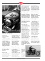
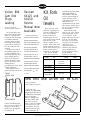
WINTER 1995
THE KAWASAKI TECHNICAL MAGAZINE
VOL. 8 NO. 4
INSIDE
Features
Micro-K
Regional
News
Tech Tips
‘96 Cruisers . . . . . . . . . 2
Older Vehicle Parts . . . 3
Update. . . . . . . . . . . 4
Latest Information . . . 5
lnstall Inlet Guides . . . 6
ZX-7RR Fork Tool. . . . 6
ZXi Trim Cables . . . . . 7
Oil Drum Storage. . . . 7
Vulcan 800 Plugs. . . . 8
KX Fork Oil levels . . . 8
KLF/KEF Starting . . . . 9
MULE™ Noise. . . . . . 10
KAF620 Cooling . . . . 11
increase air velocity at low
rpms, for improved low
speed carburetion and
performance. The exhaust
system’s internal diameter
is also reduced in size by
6.4mm to increase exhaust
gas velocity at low rpms,
also contributing to
improved low speed
performance. A reduction
in compression ratio (from
10.8:1 down to 10.2:1) and
a 26% increase in flywheel
effect combine to smooth
out the power delivery. In
the transmission, second
and third gear ratios are
slightly taller to match this
new powerband.
Vulcan 800 Classic
The Vulcan 800 Classic
follows on the heals of the
popular Vulcan 800
introduced last year.
Although initially the two
motorcycles seem to be
completely different, closer
examination reveals that
they share an identical
chassis and engine. The
transmission is revised
slightly, however, with
lower first and second gear
ratios and a final drive
ratio that is about 14%
taller for less engine rpms
at cruising speeds. The
transformation to classic
styling is achieved by
carefully changing a few
key components. The most
obvious
change is up
front where
a fat 16-inch
front wheel
replaces the
skinny 21inch wheel
found on
the
standard
Vulcan 800.
To complete
the front
Boasting form and function, cruisers are much
more than meets the eye!
by Patrick Kelly
Training Development
Coordinator
Market trends indicate
that long, low and chromecovered motorcycles,
commonly referred to as
“cruisers,” are becoming
more and more popular.
1996 brings nine cruiser
models from Kawasaki,
including four all new
models. Since you will
probably be seeing more of
these chromed customs in
your shop, let’s take a
closer look.
Vulcan 500 LTD
The Vulcan 500 LTD is
all new this year. And
from the first look you can
tell that the styling is
completely different. The
seat height is lower, the
wheelbase longer and the
rake is kicked out farther
to give it that low and lean
look. But the engine
externally appears very
similar to the standard
Vulcan 500 engine.
However, inside the
engine there are many
differences, all designed to
give the engine more lowend power and torque.
Both intake and exhaust
cam duration are reduced
by 16° to improve
efficiency at low rpms. To
go along with the
increased efficiency at low
rpms, the LTD gets smaller
carburetors, going from
34mm to 32mm. The
smaller carburetor bores
WINTER 1995
2
K-TECH NEWS
end transformation, a
24mm shorter front fork
with outer covers is used
along with a large classic
style front fender. A large
classic style fender is used
out back as well. Other
differences include a twopiston front brake caliper
instead of a single piston
caliper; lower, wider
handlebars; a new seat that
looks like a two-piece
design but is one piece; a
larger headlight and a
different taillight.
Vulcan 1500 L
The Vulcan 1500 L is
not, strictly speaking a
new model, having been
introduced in Europe two
years ago. The 1500 L is
technically identical to the
standard 1500, but a few
cosmetic differences–
chrome spoke wheels
instead of cast aluminum
wheels and a wide flat
“drag” style handlebar
instead of a pull back
handlebar – give the 1500
L its own custom look.
Vulcan 1500 Classic
At first glance, the
Vulcan 1500 Classic
appears all new; and in
this case, it’s true, as the
Classic edition of the 1500
features an all-new chassis
and a thoroughly restyled
Continued on page 12
K-TECH News
Vol. 8 No. 4
Winter 1995
K-TECH News Staff
Micro-K
Publisher
Kawasaki Tech Services
Older Vehicles:
Are the parts still available?
Publications Manager
Don Church
by David Pyle
Parts Publications Specialist
Executive Editor
Gary Herzog
Editor-in-Chief
Gregg Thompson
Communications Editor
Patrick Kelly
Regional Editors
North and East
Fred DeHart
Central and South
Walter Rainwater
West
Robert Taylor
Contributors
Shannon Beeson, Dave Behlings, Keith
Pestotnik, David Pyle, Ray St. John
Graphics/Production
Graphic Art
Gregg Thompson
Photography
Dave Corey, Rich Cox, Kevin Wing
Copy Editor
Pat Shibata
Production
Holland Marketing Services
©1996 Kawasaki Motors Corp., U.S.A.
All rights reserved.
Published by Kawasaki
All suggestions become the property of KMC.
Sending a service suggestion gives Kawasaki
permission to publish and/or use it
without further consideration.
Specifications subject to change without notice.
does not mean that the part is still available. Your best
bet is to do an Item Status Inquiry an K-Share or call
your Distribution Center. This way, you can verify the
parts status as well as inventory level. If the inventory
level is low, it might be a good idea to inform your
customer of this, and that you may or may not be able
to get the part.
If the part is cancelled, all hope is not lost. Use K-
As time goes on, more customers are purchasing
Share to run an ad an the Item Locator Service. This is
and rebuilding “vintage” bikes or, in some cases, just
also a great way for dealers to move some alder
holding an to their favorite motorcycle, ATV, or Jet Ski
inventory. I talk to dealers all the time who procure
watercraft, a bit longer. The result is that more and
hard to find or cancelled parts through the Item Locator
more customers are looking for parts for older vehicles.
Service.
Let’s look at some ways that can help you avoid telling
Part of good customer service is good intentions an
a customer that you can get a part and then finding out
your part. Even if you can’t get the part that the
that the part is no longer available.
customer is looking far, taking the few extra steps to
Don’t just look in the Retail Price Guide. The price
avoid an unhappy customer is well worth your time.
guide is only accurate up to the day it was printed. Just
That customer will return for other parts down the road
because the part number looks good in the price guide
if they know you are willing to go the extra mile.
ABS
Training
Materials
Now
Available
ABS
Training Manual
especially important to
European consumers.
Anti-lock braking systems
may be the wave of the
future.
But you probably don’t
really care how many
different bikes have antilock braking systems or
who likes them. What you
want to know is how to
work on the one that just
appeared in your shop.
Anticipating this need,
Kawasaki Service Training
and Communications
Department has just
released a new video tape
and a training manual
which explain how the,
by Ray St. John
Supervisor, Technical
Writing
The Anti-Lock Braking
System (ABS) on the newfor-'96 ZXll00-Fl is an
important step forward for
Kawasaki’s motorcycle
technology. Anti-lock
braking systems have been
in use in automobiles for
several years and are
becoming more and more
popular. Several brands of
motorcycles offer anti-lock
braking systems on chosen
models, and they are
WINTER 1995
3
K-TECH NEWS
w
anti-lock braking system
works on the GPZll00
ABS, and what to check
first if it doesn’t work. The
video tape is 18 minutes
long and one of the most
important things it covers
is how to read the selfdiagnosis feature of the
system. The 21-page
training manual also
includes complete and
detailed wiring diagrams.
The video is available
for $35.95 ($25.00 for
Technical Training Video
Club members) plus
shipping, handling and
applicable sales tax by
calling (714) 770-0400, Ext.
2472. Members of the
Kawasaki Technical
Training Video Club have
already received the video
automatically. Dealer cost
for the training manual is
$6.95, and may be ordered
under P/N 99964-0059-01.
One copy of the training
manual is included with
the video tape, free of
charge.
w
NORTH & EAST
One of the most
frequently asked questions
at our training classes is
Where can I find
information on this
particular Kawasaki
product?” A good service
technician needs to know
where to find product
information. It is not
possible to remember every
detail for all the products a
dealership sells and
services. The trick to saving
SOUTH & CENTRAL
The training season thus
far in the south and central
regions has been fairly
WEST
New West Region Training Instructor
The big news in the west
region this issue is the new
west region training
instructor, Mr. Robert
Taylor.
Robert comes to
Kawasaki with over 20
years of experience in the
industry. He spent the past
time and maintaining
credibility with your
customers is knowing
where to find the
information needed. Listed
are the materials I use daily
for service and product
information. How many
are currently available at
your dealership? Take
some time to find them and
familiarize yourself with
their content. You will save
time and dollars in the
future!
I wish you a happy and
profitable new year, and I
look forward to seeing you
at one of Kawasaki’s
training classes soon!
Accessory Catalog
Accessory Price Guide
Assembly and Preparation Check
Lists
Assembly and Preparation
Manuals
Dealer Assistance Directory
How We Stack Up
K-FAX Document Retrieval
System
K-Tech News Magazine
K-Tech News Microfiche
Kawasaki Good Times Magazine
Kawasaki Times Newspaper
Marketing Bulletins
Microfiche Check list
Model Application Microfiche
Model Recognition Manuals
w
Fred DeHart
201 Circle Drive N. #107
Piscataway, NJ 08854
(201) 469-1221
active, with most classes
having good attendance.
One of the classes that has
not been offered yet but
well worth attending is
Product Update '96.
1996 brings numerous
new and updated products
to our line-up, such as the
new 800 and 1500 Classic
Vulcans, the new ZX-7R
and ZX-7RR, the new GPZ
1100 ABS and, of course,
the incredible new 1100
ZXi Jet Ski® watercraft.
so if you want to know
what is new about these
products, or if you are just
curious about the meaning
of the new for '96
acronyms, KAIS and KATS,
then be sure to take a look
at our training schedule
and pick an update class
date that suits your
schedule. We will get you
up to speed on all the latest
features and ready for the
eight years at a leading
technical training school
where he designed and
taught numerous courses
related to all aspects of
motorcycles, ATVs and
personal watercraft. Most
recently, he was director of
the school’s marine
program, which included
outboards, sterndrives and,
of course, all brands of
personal watercraft.
Robert’s extensive
knowledge and
background bring a new
dimension to Kawasaki’s
training program. Take
advantage of Robert’s
knowledge by signing up
for a couple of training
classes soon.
WINTER 1995
w
4
K-TECH NEWS
Owners Manuals
Parts Bulletins
Parts Microfiche
Parts Price Guide
Product Brochures
Product Sales Guides
Retail Sale Price Sheets
Roads Magazine
Sales Bulletins
Service Bulletins
Service Manuals
Service Specifications Handbook
Service Training Manuals
Service Training Videos
Special Tool Microfiche
Team Green News Magazine
Warranty Policy and Procedures
Manual
busy spring and summer
months ahead.
And while you are
signing up for Product
Update, be sure to sign up
for any other classes that
might help you fine-tune
your skills. I hope to see
you in class soon!
w
Walter Rainwater
6110 Boat Rock Blvd. S.W.
Atlanta, GA 30378
(404) 349-2000
JUST A NOTE ...
As you may know,
Kawasaki Motors Corp.,
U.S.A. recently took
over distributorship
responsibilities for the
seven “Rocky
Mountain” states
previously handled by
Rocky Mountain
Kawasaki (RMK). – Ed.
New Tech
Service
Employees
by Don Church
Manager, Service Training
and Communications
ATV product lines.
Prior to joining RMK,
Keith spent 12 years in the
field as a dealership
technician while pursuing a
successful racing career
that included motorcycles,
snowmobiles, ATVs and
watercraft. As you can see,
Keith’s diverse background
and experience with
Kawasaki give him a
wealth of knowledge that
will lead to success in his
new position and will
result in better products for
Kawasaki customers. This
is what’s referred to as a
“win-win situation.”
Welcome, Keith!
from Kansas State
University in 1992.
Shannon enjoys racing Jet
Skis and recently competed
in the 1995 Skat-Trak
World Finals at Lake
Havasu City, Ariz., on his
Kawasaki XiR. Welcome,
Shannon!
w
Shannon Beeson, New
KMC Hot Line Technical
Shannon Beeson started
work with Rocky
Mountain Kawasaki in
1993 as a Kawasaki
Support Technician. No
stranger to most Kawasaki
dealers in the RMK region,
he had assumed most of
the day-to-day functions of
Kawasaki technical and
customer support at RMK.
He joined KMC in the fall
of 1995 to work as a
Product Support Specialist
on the Kawasaki Technical
Hot Line.
Growing up in a familyowned Kawasaki
Dealership in Western
Kansas, Shannon gained
much experience with the
ATV and MULE™ product
lines as well as street bikes
and personal watercraft. In
the midst of a busy work
career, he graduated with a
Bachelor’s degree in
mechanical engineering
Kawasaki’s
telephone lines
are being
upgraded to
accommodate new lines in order to
offer better service for our dealers.
This change will affect our K-FAX line.
The number is being changed to: (714)
460-5663. This bulletin also has
stickers attached with the K-FAX and
Hot tine numbers you can put right on
your phone. Please make a note of
this change on your K-FAX materials.
For more information on how to use
K-FAX, refer to Service Bulletin GEN
95-01.—E d .
NEWS FLASH!!
Keith Pestotnik, New
KMC Technical Services
Employee
In 1984, Keith Pestotnik
joined Rocky Mountain
Kawasaki-the former
distributor for Kawasaki
products in the seven-state
region of the Midwest –
working as Regional
Service Manager for
Kawasaki, Mariner and
Force outboard motors,
and Polaris snowmobiles
and ATVs. His duties
included dealer technical
support, dealer technical
training, warranty
administration and
consumer services. He later
moved on to managing
distribution functions for
the parent company of
RMK, Masek Distributing
of Gering, Neb.
In the summer of 1995,
Keith relocated to Southern
California with his family
to join KMC as a Senior
Product Quality Engineer.
His special focus will be on
the Kawasaki MULE™ and
WINTER 1995
ATTENTION
K-FAX USERS
The '96 1100 ZXi has some important last minute
additions! Two exciting new features have been added
since the 1100 ZXi's introduction at the national dealer
meeting in October. These features were originally
slated for the '97 model, but through extra effort from
KHI, these
features will be
on the '96 model.
New to the
industry is the
Kawasaki Air
Induction
System, or KAIS.
Air outlets at the
aft ends of the
inner strakes are
Continued on page 6
5
K-TECH NEWS
’961100 ZXi
Important
Additions
Continued from page 5
connected to tubes which
go into the engine
compartment. As the boat
is under way, negative
pressure generated at the
end of the inner strake
draws air from the engine
compartment to the bottom
of the hull. This reduces the
drag between the hull and
the water and also reduces
resistance due to
turbulence at the end of the
strake. To prevent water
from entering the hull if the
boat capsizes, the tubes are
crossed in the engine
compartment. This assures
that one end of the tube
always remains above the
waterline.
KAIS reduces the drag
and resistance between the
hull and the water,
meaning quicker
acceleration and a higher
top speed. And because
this is accomplished
without any modifications
to the pump or engine,
there is no added strain or
TIPS FROM
THE FIELD:
stress to the engine or
driveline components.
Also added just in time
for production is the
Kawasaki Automatic Trim
System, or KATS The
system monitors engine
rpm and adjusts the trim
position accordingly for
optimal acceleration from a
standing start. As engine
rpm rises past 2000, the
system waits three seconds
and then moves the trim
nozzle up for 1.5 seconds,
stopping at approximately
the level position. When
the engine rpm drops
below 2000 for more than
one second, the system
brings the nozzle to the full
down position. The KATS
allows riders to concentrate
on enjoying the 1100 ZXi's
formidable acceleration
without having to monitor
the trim position. The
system can be turned off by
manually adjusting the
trim or by a switch on the
left handlebar.
So be sure to take note of
and let everyone know
about these exciting new
features found exclusively
on the industry’s premier
watercraft, the Kawasaki
Jet Ski 1100 ZXi!
Kevin Williams, from
Walt’s Kawasaki in Lake
Havasu City, Ariz., wrote
to us with a time-saving
suggestion for replacing
the plastic jet pump inlet
guide on our 1992-'95 750
watercraft.
Kevin was looking for a
You will have to drill a
small hole in the intake
guide to align with the
hole in the intake grate.
Bolt the modified intake
grate to the hull and pump
housing. Then, holding the
intake guide in place, mark
it through the hole in the
grate. Then drill a hole in
the guide the right size for
the screw you are going to
be using. You’ll have to
make a small spacer (about
l/2") to go between the
intake guide and the grate.
Then glue the guide in
place using your special
tool, spacer and screw to
“special tool” to hold the
intake guide in the proper
position while the glue
dries. He found the tool
already in his shop: a
discarded 750 jet pump
intake grate.
He removed the two
outside vanes from the
grate, but left the middle
one in place. This left
enough room to get his
hands in to work on the
guide. The grate already
has a small hole that lines
up right over the intake
guide.
hold it there while the glue
hardens.
We suggest you use the
factory glue when
installing one of these
guides. You can order it
from Kawasaki using P/N
99996-5501.
Whenever we print a
technical tip that was sent
in from the field, we
always send a $100 check
to the person who
submitted it. So Kevin
Williams, thank you and
the check is in the mail
(really).
Installing Jet
Pump Inlet
Guides
w
ZX-7RR Front
Fork Tool
The cartridge type front forks on the new ZX7-RR
(ZX750-N1) require a special new tool to hold the
cartridge during disassembly. If you expect to be
working on any of these forks in the future, you should
order one of these tools (P/N 57001-1396).
w
WINTER 1995
6
K-TECH NEWS
w
New Water
Seal for ZXi
Trim Cables
by Dave Behlings
Product Support Specialist
Proper
Storage of
Oil Drums:
What You
Should Know
by Gregg Thompson
Product Support Supervisor
Care should be taken
when storing oil drums at
your dealership to prevent
water contamination of the
oil. It is really best to store
oil drums indoors to
prevent exposure to
moisture and extreme
temperature changes.
Unfortunately, many shops
simply can’t spare the room
inside their shop to store
their drums.
When drums are stored
outside, water can collect
on top from rain or snow.
As a drum heats up and
cools down from day to
day, the oil and air inside
housing has a small rubber
boot at each end that the
cable slides through as the
trim is adjusted.
Apparently, water can get
past these boots in certain
circumstances.
For 1996 models with
electric trim will have a
new style boot on the
pump end of this cable.
The change will actually
occur mid-year on some
models. The new boot is
an accordion-style one that
fits tight (with zip ties) to
the housing and the cable.
It moves with the cable
instead of the cable sliding
through it. We expect this
We’ve had some
problems on the 1995 ZXi
900s and 750s with water
leaking up the trim cable
and into the trim control
box. Water in the trim box
always goes undetected
and eventually damages
one or more components,
leaving the system
inoperative. This cable
around the bung. A
2x4 under one edge
of the drum as
shown here will do
the job.
Also, be sure to
rotate your older
drums to the front
when new ones are
delivered. Always
use the oldest oil
first. Even when
stored properly, oil
drums will collect
moisture from the
air if they’re stored
long enough.
expand and contract. As it
expands, air is pushed out
past the bung. As it
contracts, whatever is
around the bung gets
pulled into the drum. If
rain water has collected on
top of the drum, that’s
what gets pulled inside–
and that’s bad.
Roper storage can
reduce the chances of this
happening. CITGO
Petroleum Corp. offers
several suggestions. They
recommend building a
storage shelter where
drums can be stored
on their side, as
shown in this
illustration.
The drums must
be stored with the
bungs in the position
shown to prevent any
contamination.
If building a
shelter is not in your
near future, you
should at least store
the drums propped
up and positioned so
water doesn’t collect
WINTER 1995
w
7
K-TECH NEWS
design to be watertight.
If you find water in the
trim control box on a 1995
ZXi 900 or 750, install one
of these new style boots
(P/N 490163702) and zip
ties (P/N 92037-1173) on
the cable. The large end of
this new boot will fit right
over the existing small
boot. Also, don’t forget to
check the condition of the
seals and O-rings on the
wire harness connectors
and cable mount at the
box, and the large O-ring
in the cover. These could
also be a source of water in
the trim box.
w
Vulcan 800
Cam End
Plugs
Leaking
by Gregg Thompson
Product Support Supervisor
We‘ve had quite a few
calls on the Hot Line lately
about oil weeping from
around the cam end plugs
on VN800s. Often the
servicing dealer replaces
the O-rings on the plugs
only to have it return in a
few days with the same
problem.
We have had some of
the problem plugs sent in
to us for inspection. We
discovered that they have
some molding flash (a
small rib of unwanted
plastic) inside the O-ring
groove. We believe this
molding flash is
preventing the O-ring from
sealing completely.
The solution is not to
replace the plug, but to cut
REMOVE
MOLDING FLASH
KX Fork
Oil
levels
Revised
KX125 and
KX250
Service
Manual Now
Available
There has been some
confusion regarding fork
oil levels on KX125s and
250s. This confusion
usually results from
comparing the oil level
specs in the service manual
with the ones in the
owner's manual. If you
compare them, what you’ll
notice is that the specs are
not the same! There is good
reason for this and it’s
important to understand.
The service manual
shows the oil level for a
By the time you read this, the
revised service manual for the 1994'96 KX125 and KX250 should be in
stock. Order P/N 99924-1168-02. The
revised manual includes 20 pages of
information on the 1995 models,
covering their differences from the
'94s. Included ore new torque and
locking agent specs; cable, wire and
hose routing changes; as well as a
FORK
complete set of service specifications for
the engine, transmission, final drive,
covers the new 46mm forks and other
service specifications.
w – Ray
St. John
OIL
LEVEL
TABLE
M ODEL
OIL L EVEL
(Spring Removed,
Fully Compressed)
ADJUSTABLE R ANGE
1994 KX125-K1
1994 KX250-K1
1995 KX125-K2
1995 KX250-K2
1996 KX125-K3
1996 KX250-K3
120±2mm
130±2mm
90~150mm
90~150mm
120±2mm
90~150mm
115±2mm
105~140mm
and electrical system (with wiring
diagram). The '96 model information
fork that is first being filled
after being drained or
disassembled. After the
fork has gone through its
stroke one time, the oil
level changes (rises) and a
different oil level
specification must be used.
The owner’s manual shows
the oil level for a fork that
has been ridden.
If this doesn’t make
sense to you, read “Upside
Down Forks-Oil Levels
vs. Air Volume” in the
Winter 1989 issue of K-Tech
News. If you don’t have
that issue, you can find it
on grid D-3 of the March
1995 K-Tech News
microfiche. Below is a
reference chart with the
service manual specs
(newly assembled forks)
for the 1994-'96
models. w – David Pyle
New Fork Seal Driver for '96 KXs
by Gregg Thompson
Product Support Supervisor
O-RING GROOVE
out the unwanted plastic.
Once you have cleaned up
the groove in the plug,
install a new O-ring and
put it back in.
w
Again this year,
Kawasaki has significantly
changed the front forks on
the KX250 (K3) and KX125
(K3). For '96, these
inverted cartridge-type
forks have 46mm inner
tubes. This, of course,
means it’s time for another
fork seal driver for your
tool collection. The part
number for the new seal
driver is 57001-1395.
w
WINTER 1995
8
K-TECH NEWS
CLEAN
THAT
HUB
One thing some mechanics
overlook (especially at the races)
when changing a KX bike rearbrake disc or sprocket is the
mounting flange on the hub. Make
sure you clean the surface of the
flange that the disc or sprocket
mounts against. Even a small
amount of dirt on that surface can
cause the disc or sprocket to warp
when the mounting bolts are
tightened. – David Pyle
w
KLF/KEF3OO
Cold
Weather
Starting
by Shannon Beeson
Product Support Specialist
Over the years, we have
heard numerous
complaints of starting
problems on KLF300s in
cold weather. Generally on
these models, getting fuel
into the combustion
chamber is not the
problem. The problem is
getting the fuel that’s in
there to ignite. Fuel enters
the cold engine in liquid
form. For combustion to
occur, some of it must
vaporize before the
remaining liquid fuel wetfouls the spark plug. If you
have a KLF300 that is
getting fuel into the
combustion chamber, but
it will not start, consider
the following items when
diagnosing the unit:
PLUG FOULING:
Occasionally we hear of a
KLF/KEF300 that will not
start unless the customer
replaces the spark plug
each morning. The plug is
usually sooty black and
wet when removed. The
black color is from a rich
running condition that
existed when the unit was
last run. The sooted plug is
then wet-fouled by the rich
mixture created by the
choke. An improper idle
mixture screw setting or an
incorrect fuel level can be
FUEL QUALITY:
Is the fuel in the unit fresh
(recently purchased)?
Many users of this type of
product have their own
fuel storage tanks. Often
this fuel has been
purchased some time ago
(in the spring or summer).
If so, the fuel should be
removed from the unit and
replaced with fresh
seasonally blended fuel
(don’t forget to drain the
carburetor float bowl).
Winter fuels are specially
blended to enhance
vaporization in cold
weather. In addition,
vaporization can be
improved by increasing
the cranking pressure in
the combustion chamber.
First, verify the engine
condition by performing a
compression and/or
leakdown test. Then
ensure the best possible
cranking pressures by
setting the valve clearances
to the loose end of the
specification.
3mm to
CENTER
OF
HOLE
SPARK QUALITY:
The KLF/KEF300s have a
battery ignition system.
Anything that can be done
to improve battery voltage
will boost spark energy.
Inspect the battery. Make
sure it has been properly
serviced, check its voltage,
and do a load test on it.
Additionally, a light
viscosity oil in the engine
will allow it to crank more
easily in the cold. The
starter will draw less
current, allowing system
(ignition) voltage to
remain higher while
cranking. Spark quality
can be monitored by using
an inductive timing light.
WINTER 1995
the cause of the sooted
plug. Make sure these are
adjusted correctly. (Make
sure the customer is not
leaving the choke on while
riding.) Do a quick check
of the air cleaner element,
too, just to be sure it isn’t
dirty and restricting air
flow.
If you have adjusted the
idle mixture screw and
fuel level, but the unit
continues to soot the plug
at low speeds, check to see
if the main fuel passage is
feeding fuel at idle. With
the inlet air duct removed
9
K-TECH NEWS
and the engine idling, use
a mirror and light to look
in the carburetor throat. If
you see fuel coming from
the main passage around
the needle, you should
modify the slide to raise it
slightly at idle. Raising the
slide’s at-rest position will
decrease the air velocity
over the main fuel nozzle
and reduce the tendency to
draw fuel through it at
idle. Do this, using the
following procedure:
1 Remove the
carburetor
slide.
2 Drill a
5/64" hole at
the ridge on
the slide stop
contact
surface, 3mm
from the slide
body as
shown.
3 Install a
l/4" #4 sheet
metal screw
in the hole.
The head of
the screw
should
provide
about 2mm
added lift to the slide at
idle.
4 Assemble the
carburetor and readjust the
idle mixture screw if
needed.
This modification
should reduce the amount
of fuel feeding through the
main passage at idle, and
as a result, extend plug life.
Following the above
procedures should ensure
the best possible cold
starting. And don’t forget
that good engine condition
is also very important.
w
Front
Drive
Train
Noise on
MULE™
2510
by Keith Pestotnik
Senior Product Quality
Engineer
Some KAF620-A's
(MULE™ 2510) will
develop an abnormal
rattling noise from the
front drive train. This noise
is normally heard only in
2-wheel drive. It usually
begins with the vehicle at a
constant speed and light
load when little or no
noise. This reinforced
rubber washer is thick
enough that, when
installed properly, it is
compressed between the
propeller shaft yoke and
the differential. The
pressure it applies to the
yoke holds the yoke tight
and prevents it from
rattling.
To get one of these
washers, call the Technical
Hot Line and ask for the
NPN Noise Damper
Washer for the KAF620-A.
It currently has no
Kawasaki part number.
To install one, pull the
front propeller shaft yoke
off the front differential
pinion shaft (see page 1122 of the service manual)
and install the washer onto
the pinion shaft, observing
the following:
torque is transferred
through the front drive.
Once the noise begins, it
will probably continue
until the vehicle stops or at
least changes speed
significantly. If this sounds
like your problem, we
have your cure.
Actually, this problem
was first discussed in the
Winter 1993 K-Tech News,
but we’ve learned more
and would like to pass it
on to you.
This noise is caused by
clearance between the
splines in the propeller
shaft yoke and the pinion
shaft of the front
differential. In early units,
a special tape was put on
the splines to dampen the
noise. On later units, an oring groove and o-ring
were added to the pinion
shaft, but the noise still
persists on some units.
At KMC, we have
developed and tested a
durable washer/damper
which, when installed on
the front pinion shaft, will
significantly reduce this
WINTER 1995
l Remove and discard any
tape or O-ring found on
the pinion shaft.
l Clean the splines in the
yoke and on the pinion
shaft and coat them with
10
K-TECH NEWS
the toughest grease you
have. (Bel Ray Waterproof
grease or a good anti-seize
compound will work well.)
l Make sure the front and
middle yokes on the
propeller shaft assembly
are aligned in the same
plane.
l Make sure all differential
mounting bolts are
tightened properly.
l To compress the NPN
washer, push the propeller
shaft bearing housing to
the left while tightening its
mounting bolts.
When done, check to
make sure the new rubber
washer is held tight
between the propeller shaft
yoke and the pinion shaft
nut. If it is loose, the
propeller shaft bearing
housing must be moved
farther to the left. To do
this, you might have to
enlarge or elongate the
mounting holes in the
frame.
w
KAF620
MULE™
Overheating
by Keith Pestotnik
Senior Product Quality
Engineer
It may not surprise you
to know that air in the
KAF620 MULE™ cooling
system can lead to engine
overheating. What might
surprise you is how little
air it takes to cause a
problem, how easy it is to
get that air into the system
and how difficult it can be
to get it out. A fairly small
segment of air, if it reaches
the water pump, can cause
an air lock that will stop
coolant circulation. If this
occurs and the operator
doesn’t notice the
temperature warning lamp
(or ignores it), serious
engine damage can result.
To prevent overheating,
the cooling system must
have all the air purged
from it. Bleeding is
difficult because there are
several high points in the
system, plus pockets in the
water jackets of the engine
that trap air. To fill the
KAF620 cooling system, do
the following steps in
exactly this order:
when coolant overflows
the radiator.
4 Install the bleeder bolt
in the intake manifold
when coolant overflows
there.
5 Install the carburetor
hose when coolant flows
from it. (Keep the end of the
hose elevated until coolant
runs out.)
Note: No matter how
carefully you follow steps
1 through 5, the system
will still trap air (mostly in
the engine’s water jackets).
Continue the procedure.
6 Fill the coolant
recovery tank to above the
“F” mark.
7 Elevate the front end
of the vehicle
approximately 12 inches.
Parking it on an incline is
fine.
8 Start and run the
engine at full governed
REM, adding coolant at the
filler neck as air escapes
the system. Caution: If the
governor is not adjusted
properly, the engine could
over rev and suffer internal
damage.
9 Continue topping off
the filler neck until the
coolant begins to let off
steam. At this point, the
thermostat is beginning to
open and you must install
the filler cap very soon to
avoid a geyser of hot
coolant when the
thermostat opens fully.
10 Disconnect the
cooling fan at the bullet
connector (black/yellow
wire) just behind the gas
pedal. Drive the vehicle
until coolant begins to rise
in the recovery tank. Note:
If the temperature warning
light comes on, reconnect the
cooling fan immediately and
allow it to cool down.
Driving it on rough terrain
will help jar loose any
trapped air bubbles. Once
the coolant begins to rise in
the recovery tank,
reconnect the fan wire.
11 Let the engine cool
all the way down, making
sure the coolant recovery
tank never empties
completely (keep it at or
above the “F” mark).
12 Repeat steps 10 and
11 until you no longer
have to add coolant to
keep it above the “F”
mark.
1 Remove the radiator
cap, filler neck cap, bleeder
bolt at the intake manifold
and the upper coolant hose
at the carburetor "T"
fitting.
2 Slowly add coolant at
the filler neck (not at the
radiator).
3 Install the radiator cap
WINTER 1995
11 K-TECH NEWS
When a KAF620 is
severely overheated in use,
there can be considerable
hidden damage that will
result in further
overheating problems if
not corrected. If you
suspect that one has been
severely overheated, check
for coolant flow at the
filler neck with a cold
engine. Usually after a
severe overheating
condition, the thermostat
will be stuck in the open
position. If you encounter
this condition, check all of
the following items for
damage:
Coolant filler neck
(eroded at the sealing
surface for the cap)
l
Rocker arm covers
(partially melted from
heat)
l
l
Thermostat (stuck open)
l Water pump impeller
(melted, eroded)
l Cylinder head (warped
and leaking at head gasket
surface)
w
Take a Closer
Look
Continued from page 2
and retuned engine.
The engine is based on
the existing Vulcan 1500
engine, sharing the same
basic layout and 50° angle
between the cylinders, but
is retuned for more lowend torque and restyled for
a more classic appearance.
A single Keihin CVK
40mm carburetor
equipped with an
accelerator pump replaces
the dual CVK 36mm carbs
used on the standard 1500
engine. The single
carburetor, located on the
right side of the engine,
offers easier carburetor
access for simpler
servicing. Air reaches this
new carburetor through a
series of chambers,
expanding and contracting
three times to reduce
intake noise. The first
chamber is located
underneath the fuel tank,
the second chamber is the
chrome covered air box on
the left side of the engine,
and the third chamber is
the chrome covered air box
on the right side. A single
air cleaner element is
contained in the left air
box.
Milder camshafts, 8° less
duration and 0.5mm less
lift on the intake cam and
8° less duration and 0.2mm
less lift on the exhaust cam,
smooth out the power
delivery and improve lowend torque and power feel.
The new camshafts also
allow the use of single
valve springs instead of
the dual valve springs
found on the standard
camchain tensioners are
used to further reduce
mechanical noise. The new
tensioners are a
combination of a ball lock
type and a ratchet type.
The two types of locking
mechanisms combine to
prevent any rearward
movement and thus noise,
as the tensioner rod
extends outward taking up
camchain slack.
Other engine changes
include a wider oil pump
rotor, up from 22mm to
30mm, and a plunger-type
oil pressure relief valve
replacing the ball-type
relief valve.
Like the standard 1500,
the 1500 Classic engine is
liquid cooled. But, the
Classic’s radiator is placed
between the frame
downtubes and the
radiator hoses are carefully
routed to preserve the
simple air-cooled look.
And even though the
radiator is 90mm shorter
than the standard 1500’s
radiator, it is 8mm thicker,
so cooling capacity is
unchanged.
The engine externally is
carefully styled, too. The
most obvious change is the
location of the rear exhaust
outlet. The rear cylinder
head is redesigned so that
1500 engine. This single
spring is identical to the
1500's outer spring. The
single valve springs reduce
mechanical power losses
and lower valve train
noise. The Classic engine,
like the standard 1500
engine, uses hydraulic
valve lash adjusters to
eliminate valve clearance
adjustments. Also
contributing to a smoother
powerband is a new digital
ignition (which does not
sense engine vacuum) and
increased flywheel effect.
Flywheel effect is
increased by 25% by
additional weight on the
balancer gear.
Both piston pin
locations are raised 0.5mm
to lower the piston
position at TDC, reducing
compression from 9.0:1 to
8.55:1 and further
contributing to a smoother
power delivery. Piston pin
location is also changed to
reduce piston slap noise.
The front piston pin
location is now offset
2.0mm toward the intake
(from l.0mm toward the
intake on the 1500 A) and
the rear piston pin location
is now offset 2.0mm
toward the exhaust (from
1.0mm toward the intake
on the 1500 A). New
WINTER 1995
12
K-TECH NEWS
the exhaust exits out the
right side instead of the
left. The shape of the
engine side covers and
cylinder head covers is
also changed to give the
engine a simpler, more
nostalgic appearance. And
of course, there is chrome
everywhere!
The transmission is
revised to take advantage
of the Classic’s wide
powerband. Although still
a four-speed, second
through fourth gears are
taller, and engine rpms are
reduced by over 19% while
cruising in top gear.
The 1500 Classic’s
chassis is all new, too. The
frame is a steel double
cradle unit with a
removable right downtube
for easy engine access. The
rigidity of this new frame,
combined with a very rigid
swingarm, gives the big
Classic superior handling
qualities. A sturdy 41mm
Showa fork handles the
suspension up front and
twin pm-load adjustable
shocks soak up the bumps
out back.
This sophisticated yet
simple-looking machine is
topped off with styling
cues that harken back to an
earlier era in motorcycling.
Huge flowing metal
fenders, front and rear;
simple instrumentation
mounted on top of a large
wide fuel tank; wide
comfortable handlebars;
huge headlight and twin
exhaust pipes all combine
to inspire a feeling of days
gone by.
As you can see, looking
at all of the creative
engineering for both form
and function, there is
much more to a Kawasaki
cruiser than meets the
eye.
w