1
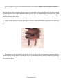
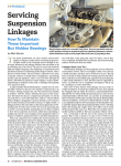
Thanks for Ordering the Kawasaki Vulcan
400/800 Preload Improvement Kit
from
READ THIS BEFORE UNPACKING YOUR KIT!
This instruction booklet contains detailed steps for installing
the rear suspension preload improvement kit on your
Kawasaki 400/800 Standard (A model), Classic, or Drifter
motorcycle. Please pay careful attention to the instructions
regarding the disassembly and re-assembly of your
motorcycle. If you have any questions concerning installation
of your new Scootworks Preload Improvement Kit, please
contact us via e-mail at [email protected]. This will
ensure you receive the most prompt and accurate reply.
Rev 1.3; 3/29/2003
Copyright 1998-2003 Scootworks. All Rights Reserved.
All graphics, and descriptions in this installation instruction booklet are intended for personal use only. Any reproduction,
publishing or distribution of any materials in this booklet is strictly prohibited without the expressed written consent of
Scootworks, Inc.
www.scootworks.com
Instructions for Installing the Scootworks Preload Improvement Kit
(Be sure to visit www.scootworks.com and select [“Information Resource Center”, then “Installation
Instructions”] from the main page, for more info and pictures!)
Tools Needed:
•
•
•
•
•
•
•
•
•
•
Phillips-head screwdriver
Large torque wrench calibrated in foot-pounds
6mm Allen wrench
8mm Allen wrench
8mm socket
10mm socket/open-end wrench
12mm socket/wrench
2 each: 17mm sockets with extensions
2 each: ratchets for 17mm sockets above
A small amount of Silicone Adhesive (RTV)
The installation of the Scootworks Preload Improvement Kit follows the same procedure as lubricating
removing the rear in the Kawasaki service manual, with the addition of the rear shock disassembly. However,
Scootworks wanted to assist you as much as possible with the installation process, and developed this
instruction package. If there are any steps you feel need improvement in instructions, please email
[email protected] and specify the area you are having trouble with.
Unpacking!
The shipping container and contents must be inspected by the purchaser for damage to goods immediately upon
receipt of goods, and a claim must be filed with the carrier if damage is discovered. The purchaser must contact
Scootworks within 24 hours from receipt of damaged goods to file a claim, and for further instructions.
www.scootworks.com
Your Scootworks Preload Improvement Kit will come packed with two sets of plastic snubber spacers, two
large round metal shim plates, and these printed instructions. The info from the FAQ page is included within
these instructions.
Before beginning this task, read through this document in its entirety. It you are unclear about a specific task,
be sure to contact [email protected] for clarification.
BEGIN INSTALLATION
1. Begin by removing both side compartment covers. The RH compartment cover requires the use of the
ignition key for removal; the LH compartment cover is secured by a large Phillips screw. Once you've removed
the LH cover, place the Phillips screw back into the hole in the frame (so you don't misplace it) and set both
covers aside. In many applications, you must remove the upper exhaust pipe (from the rear cylinder), and
loosen the other pipe, to remove the inner parts of the RH side compartment cover (see below). Before
attempting step #2 below, try step #3 first… depending on the brand of exhaust pipes you have, you may
be able to avoid removal in step #2, if you are successful with step #3 first. Some brands of exhaust pipes
provide access to the fasteners securing the RH side covers, eliminating the requirement to remove pipes for
rear suspension access.
2. Remove the rear cylinder's exhaust pipe. To do so, remove the two Allen nuts on the exhaust header, where
it attaches to the engine, using an 8mm Allen wrench. Most often, this goes much more smoothly if you first
spray the inside of the allen nut with a penetrating lubricant like WD-40. Remove the black acorn nut from the
discharge end of the exhaust pipe (under the upper exhaust pipe, near the discharge end of the pipe) using a
12mm open-end wrench or socket. You'll find a black metal spacer, through which the bolt goes, that is pressed
through the rubber grommet. To avoid the potential of having it fall out unnoticed, remove it and place it aside
with the nut. Remove the black bolt from the pipe just aft (to the rear) of where the pipe enlarges and above the
pipe. This is actually a bracket that holds the two pipes together at a joint. Loosen the bolt using a 12mm
socket, then slide it back onto the pipe you're removing. Once you have the pipe off of the bike, the clamp will
be loose. Be sure to keep it with the pipe, along with the rest of the removed parts. Loosen the pipe from the
front cylinder BEFORE trying to remove the pipe from the rear cylinder. By loosening the header nuts on the
pipe from the front cylinder, and removing the two black Allen bolts (6mm Allen wrench) under the forward
pipe that attach it to the frame, you will be able to remove the rear pipe. There are more spacers in grommets
where the 6mm Allen bolts secure the lower pipe to the frame (like those used in the rearmost connection of
www.scootworks.com
the rear cylinder's pipe). These spacers will normally remain in the frame bracket, but if either is loose, remove
them and store with the Allen bolts. If the pipe doesn't come loose relatively easily, loosen the two top nuts on
the black triangular metal bracket used to secure the pipes to the frame. With patience and care, however, you
should be able to remove the pipe without loosening with the triangular bracket.
WARNING!!! Watch out for the metal exhaust gasket ring that fits between the pipe header and the engine.
When you remove the pipe from the bike, the gasket ring can easily fall out of the pipe. Don't lose it! Keep it with
the pipe for reinstallation.
3. Use a Phillips screwdriver to remove the lower cover of the RH side compartment. There are three black
Phillips screws that secure this cover. Remove the cover and place the screws back into their holes, then set the
cover aside. Use an 8mm socket to remove the four black bolts on the inner liner of the RH side cover. The
top-left bolt also secures the latch for the RH side compartment’s outer cover. Notice the small pilot hole in the
latch, to the right of the 8mm securing bolt. This is where a guide stem (molded into the compartment liner)
protrudes to insure that the bracket is in the proper position when installed. Insure that you reinstall the bracket
properly, with the hardware for the locking assembly facing out, and the guide stem through the pilot hole.
NOTE: If you have the California version of the bike and you haven't removed the emission control system,
you won't be able to remove the inner side cover box entirely. Just remove the bolts and pull the box away from
the bike as much as possible, lifting it so you can access the swing arm and frame hardware beneath it.
4. Open the door to the tool kit storage compartment, and remove the tool kit. Remove 3ea. 8mm bolts used to
secure the LH side inner compartment and ignition into the frame. Pull the rear cylinder plug wire from the
spark plug, and swing the LH side compartment/ignition out to one side. With the LH side
compartment/ignition pushed out to one side, access is available to the LH side of the upper and lower shock
absorber mounting bolts.
5. Before proceeding, raise the rear of the bike so the rear wheel is above the floor, so the tire rotates freely.
I’ve used a Centerstand lift, (www.centerstand.com - model CS8), and a Dunwell lift. Many users have reported
using a hydraulic floor jack to lift the bike while having the bike stabilized by another person. Once lifted, jack
stands can be placed under the engine cradle (not in contact with the swing arm!) to support the bike securely.
6. Use a 17mm socket to remove the lower shock bolt from the suspension pivot/lower shock absorber mount.
Once this bolt is removed, the rear wheel will drop down and rest on the floor. Use a 17mm socket to remove
the lower trailing link (suspension tie rod) bolt from the suspension pivot/lower shock absorber mount. I've
used the 17mm socket on the RH and the open-end wrench from the owner's tool kit on the LH side to remove
these bolts. If you don't secure both ends, the bolt will spin freely, once it's loose. The picture below is from the
Belt drive instructions, but it illustrates the two bolts referenced here in step #6 nicely.
www.scootworks.com
7. Use a 17mm socket on both sides of the upper shock mounting bolt, loosen and remove. It may be necessary
to raise the swingarm/rear wheel assembly high enough to allow the shock to be pulled out of the lower
suspension during removal.
8. Disassembly of the rear shock… This is the most challenging portion of the instructions, but made very
easy if you have a shock spring compressor. Scootworks offers an inexpensive shock compressor, contact us
for more details. Most motorcycle shops have shock spring compressors, and can handle this step for you in a
few minutes of time. Pull the shock, and visit your local bike shop if you need assistance. Another “homebrew” method is illustrated below. This method uses a few conventional stainless steel hose clamps used to
squeeze the turns of the spring together, providing access to the locking nut that secures the clevis to the shock
rod.
The photo above shows the shock inverted and clamped into a vise. The spring has been compressed a bit by
using hose clamps. This has allowed the factory preload shim and cup to drop down a little, exposing the
www.scootworks.com
17mm locking nut below the lower attachment clevis. Loosen this nut, screw the clevis off of the shock rod,
and remove the OEM shim washer from the retaining cup. This method of compression isn’t the recommended
one (from a safety vantage point!), but demonstrates yet another method of performing the task. A shock spring
compressor is the preferred method, and makes this job MUCH easier. Contact Scootworks if you’re interested
in one of our spring compressors!
9. Shim washer/snubber selection… The Scootworks kit comes with two metal shim thicknesses and two
plastic snubber spacers thicknesses. The following portion of the document will often refer to “bottoming out”.
This is a term often used to describe a condition where the rear wheel comes in contact with the inner rear
fender, or other parts contact the motorcycle that normally would not. Do not misinterpret “bottoming out” as
the point where the shock absorber has reached the limits of it’s stroke, but rather remember the description
printed above in this paragraph. Read below to determine your best selection criteria:
•
If your bike’s rear suspension is too soft and “bottoms out” occasionally at a stock height (not lowered),
use the thinner of the two metal shims. Many 400A/800A riders have suffered from this problem when
riding with a passenger over rough terrain. Some have even reported damaging the wiring harness to the
rear lights as a result of the tire scrubbing inside the fender. This also applies if the 400/800 Drifter (stock
height, non-lowered) rear fender contacts the lower rear portion of the seat while loaded heavily or while
riding on rough terrain. Set the preload ring to position #5 (on the 400/800A and Classic, these notches are
not numbered, and are counted from the weakest position to the strongest…with #7 being the notch that
would compress the spring the most). Reassemble the shock, and install the thinner of the two plastic
snubbers as described below.
•
If your bike’s rear suspension is too soft and “bottoms out” occasionally when lowered 1”-2”, use the
thinner of the two metal shims. Set the preload ring to position #7 (on the 400/800A and Classic, these
notches are not numbered, and are counted from the weakest position to the strongest…with #7 being the
notch that would compress the spring the most). Adjust the preload ring downwards (towards position #1)
if the ride is too stiff over small road “noise”. Reassemble the shock, and install the thicker of the two
plastic snubbers as described below.
•
If your bike’s rear suspension is too soft and easily “bottoms out” when lowered 1”-2”, use the thicker of
the two metal shims. Set the preload ring to position #4 (on the 400/800A and Classic, these notches are
not numbered, and are counted from the weakest position to the strongest…with #7 being the notch that
would compress the spring the most). Adjust the preload ring downwards (towards position #1) if the ride
is too stiff over small road “noise”. Reassemble the shock, and install the thinner of the two plastic
snubbers as described below.
•
If your bike’s rear suspension is too soft and “bottoms out” occasionally when lowered 3”, use the thinner
of the two metal shims. Set the preload ring to position #5 (on the 400/800A and Classic, these notches are
not numbered, and are counted from the weakest position to the strongest…with #7 being the notch that
would compress the spring the most). Adjust the preload ring downwards (towards position #1) if the ride
is too stiff over small road “noise”. Reassemble the shock, and install the thicker of the two plastic
snubbers as described below.
•
If your bike’s rear suspension is too soft and “bottoms out” easily when lowered 3”, use the thicker of the
two metal shims. Set the preload ring to position #7 (on the 400/800A and Classic, these notches are not
numbered, and are counted from the weakest position to the strongest…with #7 being the notch that would
compress the spring the most). Adjust the preload ring downwards (towards position #1) if the ride is too
www.scootworks.com
stiff over small road “noise”. Reassemble the shock, and install the thicker of the two plastic snubbers as
described below.
10. Now that the shim and snubber selection process is completed, and the metal shim plate has been in stalled
in the shock absorber, lets install the plastic snubber spacers. Place the selected snubber spacer under the OEM
rubber snubber currently used in your rear shock. This is easy to do, without removing or disassembling the
shock, by following these steps:
• Using a small screwdriver or other sharp object, slide the OEM rubber bumper upwards on the shock rod.
The picture below shows the OEM snubber pushed up, exposing the cavity for the Snubber Spacer to be placed
in.
• The Snubber spacers are shipped in two halves. Locate the sides of the spacer with the counterbore, apply a
small amount of silicone adhesive to both sides (RTV), and install the halves with this counterbore towards the
bottom of the shock. The picture below shows ½ of the spacer in place, to better illustrate the installation with
the counterbore down.
www.scootworks.com
• Lastly, slide the OEM bumper back down the shock rod, and press it firmly onto the top of the new snubber
spacer. The photo below illustrates the completed installation of the snubber spacer.
11. Reinstall the shock absorber in it’s upper mounting bracket. Torque this bolt to specification (43ft/lbs) at
this time.
12. Reinstall the lower shock absorber bolt in the lower suspension pivot/shock absorber mount. Reattach the
lower trailing link (suspension tie rod) to the suspension pivot/lower shock absorber mount. Torque these bolts
to specification (43ft/lbs) at this time.
13. Reinstall the LH side compartment, ignition assembly, and reconnect the rear spark plug wire. Do not
install a 8mm bolt in the rearmost inner cover mounting tab, as the large Phillips screw in the outer cover is
inserted here. Replace the two 8mm bolts in the tool kit compartment, and replace the tool kit. Reinstall the LH
outer cover.
www.scootworks.com
14. Reinstall the RH side inner storage compartment with four 8mm bolts. Don’t forget to install the latching
mechanism under the upper left 8mm bolt. Replace the RH LOWER outer compartment and secure with the
three Phillips screws. Replace the RH side UPPER outer cover and latch in place with the ignition key.
15. Reinstall the exhaust pipes (if removed in step #2). Header nuts need an 8mm Allen wrench. A 6mm Allen
wrench will be needed for the nuts under the front pipe. A 12mm socket/wrench will be needed for the aft-end
pipe connections. Don’t forget to install the exhaust gasket ring on the rear exhaust pipe, where it connects to
the engine.
NOTE: be sure to reinstall the top (rear) pipe (hand-tightening connections only) before reinstalling the lower
(front) pipe. Otherwise, it'll be tougher than crud to install it!
Congratulations!!!!
Your Scootworks Preload Kit is now installed. The following information is supplied as a supplement, to allow
you to complete the job of tuning your bike’s suspension that you’ve begun by using this Quality Scootworks
product.
FAQ’s for your new Preload Kit!
Question- Will this Preload Improvement kit work on my Drifter?
Answer- The Preload Kit will work on the Vulcan Drifter 400 and 800 perfectly!
Question- Will I need this preload kit when I lower my bike? I've heard some say they had great
results with
lowering without it, while others mentioned various problems with scrubbing and bottoming out.
Answer- There lots of our lowering kits in the field, in successful operation, without the preload kit installed.
I've installed many such lowering kits in my immediate area, as well as worked with a lot of people over the
phone or via email to assist them with "dialing in" their setup. My wife's 800 has been running about 5" lower
than stock (23.5" saddle height!) for most of the 36,000 miles she's ridden it, and she has the factory preload
with a thin snubber spacer. An example of how the variables outlined below can stack up in your favor (or
against), is where I've helped several folks additionally shorten their shock clevis and/or swap to the Shindy
shock for even more lowering. Determining your requirement for a preload kit has to be done empirically, after
you’ve lowered your bike. A rule of thumb, however, is if your total rider weight is 250 lbs. or more, and you
intend to lower greater than 2”, you’ll most likely need it.
There are many variables at play when lowering a motorcycle, including variations in
locations of
welds/pivots on the swing arm and lower suspension. Considering such, a
single solution won't work for
everyone. I've measured wide variations in assembly
dimensions that affect the geometry of the rear swing
arm. Other variables such as
combined bike and rider weight, variations in damping rate of the rear shock
affecting
shock performance, variations in the preload spring's compression value, location of
the rear
wheel within the fender (controlled largely by chain length/stretch), etc. Many
people lower their 800's
waayyy down with no problems (some at 5+"), while a few
have problems when lowered below 1" (and
even some have problems with scrubbing the tire inside of the fender while at the stock height!). When
lowering a bike, one must deal with these variables on a case by case basis. This isn't a difficult task, but
sometimes it does require a bit of patience to find the maximum lowering your bike can be operated at
successfully, in conjunction with the correct preload settings of the shock. The end result, however, is nothing
short of fabulous!
www.scootworks.com
Question- Will weight of the bike or rider impact the performance of the lowering kit and the requirement for
the preload kit??
Answer- Weight: If you ride 2-up, weigh 175 lbs. or more, or have a heavily loaded bike,
set your shock
preload to position #7. This is the setting that compresses the spring
the most. I've seen some 800's weigh in
at over 675 lbs. with accessories, and others
weigh below 500 lbs. If you weigh more, or ride 2-up, you will
want to run with less
lowering or modify the shock preload by adding the Scootworks preload improvement
kit. Measured compression values of the shocks used in Vulcan 800's vary wildly, making
the inclusion of
our Preload Kit a viable "fix", and not necessarily an indicator of some
other suspension problem. The
“Shock Preload Kit” is available from Scootworks very inexpensively, and can be used to greatly improve the
load handling capacity of the Vulcan’s rear shock absorber.
Question- I seem to be "bottoming out" on hard bumps with my preload kit installed.
Answer- If "bottoming out" is experienced with the preload metal shim and plastic snubber thicknesses
recommended in the kit, check the preload collar on the shock. This is the rotatable collar outlined within the
kit to be set at a certain “notch” position. If it’s not at the maximum preload adjustment setting (#7, the position
that compresses the spring most) move up to the next setting and test again. This can be adjusted by lifting the
rear tire off the ground, removing the LH side engine cover from the drive pulley/sprocket, and using a long
punch/5 lb. hammer to tap the collar around on the shock. If it is already at the highest preload position, choose
the next thicker component in the kit selection chart. The plastic snubber is the easiest to install, so if you’re
running with the thinner plastic snubber, switch to the highest. The progression of the kit is as follows:
#1- Thin Metal Shim plate and Thin Plastic Snubber spacer
#2- Thin Metal Shim plate and Thick Plastic Snubber spacer
#3- Thick Metal Shim plate and Thin Plastic Snubber spacer
#4- Thick Metal Shim plate and Thick Plastic Snubber spacer
Question- When I lowered the bike a lot, I noticed the tire rubs the (inside) forward
portion of the fender on
hard bumps, even with the thicker plastic snubber spacers that came in the lowering kit installed. Can this be
corrected?
Answer- Yes, the installation of the Scootworks Rear Shock Preload Improvement kit will stiffen the
suspension a bit, and additionally provide an enhanced mechanical stop to preclude this condition.
Question- Will installing the Preload Kit in my motorcycle make it ride "hard" or "stiff"?
Answer- Not specifically, depending on the selection of the components and adjustment of the kit. The rear
shock preload values used in the 400/800 Vulcans provides varying results with many riders. This is partially
determined by the total weight of the motorcycle with all accessories, total rider weight, a few manufacturing
tolerances that come into play, terrain, etc. The preload kit comes with instructions to help with correct setup,
and to provide the optimum values needed for your specific installation. When properly adjusted, the ride
should not be compromised dramatically.
Keep in mind, however, when lowering a bike one is reducing the amount of available suspension travel for
covering rough terrain. A bike lowered 5” will not have the free space available within the rear fender to allow
the tire to move as much as when it was at the stock height. This reduced clearance requires a stiffer rear
suspension setting, and a different mechanical stop location, to prevent contact with other components. This is
provided with the preload kit, and should greatly improve the ride-ability of a seriously lowered bike.
www.scootworks.com
Question- My motorcycle’s ride has always been too “soft” or “spongy”, when riding with a passenger.
Lowering the bike has made this more obvious. Is there a “fix” for this?
Answer- Yes! Many customers have reported their bike’s ride being less than desirable, especially after adding
many accessories and when riding with a passenger. Scootworks has developed a shock preload improvement
kit to remedy this. It is very inexpensive, and is available from us via our website at http://www.scootworks.com ,
or via our telephone sales line.
You're finished!
Now that you're finished, go enjoy the feel of your bike. While all of the information contained within may not
be required in your application, Scootworks wanted to provide you with the best tools and information
possible, to help insure the success of your project. Additionally, we recommend that you visit
www.scootworks.com , and read the information we have available at that site related to the Vulcan 400/800
Lowering kits. Some of the info there may also prove useful to you in getting the most from your Vulcan’s rear
suspension. In the event of any questions, feel free to email us at [email protected] . I check this
address daily, and will try to answer all questions as promptly as possible. - D. H.
www.scootworks.com