1
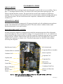
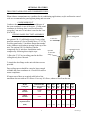
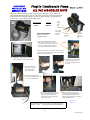
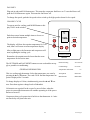
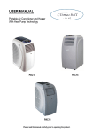
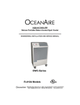
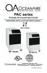
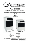
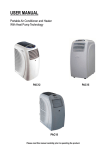
PAGE
General Description
................................................
1-2
Product Data & Specifications
................................................
3
Standard Features
................................................
4-6
Accessories
................................................
7 - 13
General Information
................................................
14
Applications
................................................
15
Installation
................................................
15
Replacement Parts Procedure
.....................................……...
16 - 17
Troubleshooting Guide
................................................
17 - 20
Preventive Maintenance
................................................
20 - 21
Piping Schematic
................................................
22
Wiring Diagrams
................................................
23 - 27
................................................
29
UNIT DESCRIPTION
SERVICE
DIAGRAMS
WARRANTY
airbossmanualtoc
GENERAL DESCRIPTION
AIRBOSS SERIES Portable Air-Cooled Air Conditioners are designed to cool an entire area by
discharging air through its 9 1/2 x 4 3/4 grille (Models PAC10 and 12), 15 x 7 (Models PAC18, 24 and
36) and 19 3/4 x 11 (Model PAC60). These self contained units are also designed to direct air to
specific areas or objects through (optional) dual 4 in. diameter nozzles (Models PAC10 and 12), 6 in.
diameter nozzles (Models PAC18, 24 and 36) and 8 in. diameter nozzles (Model PAC60). The cord
connected AirBoss Models range from 10,100 BTU/HR to 60,050 BTU/HR floor mount configuration
to satisfy most space requirements. All models are provided with casters for portability.
These models are thoroughly self-contained with the entire refrigeration system, evaporator and
condenser fan motors and electrical components neatly arranged in a platinum texture polyester powder
coated metal cabinet. Only power, and an opening to dispose of condenser hot air are required. The 24
volt temperature controller (thermostat), provides the desired comfort. The cord-connected OceanAire
AirBoss is provided with heavy-duty, swivel casters for easy handling and convenient relocation.
GENERAL REQUIREMMENTS
IMPORTANT - AirBoss Air Conditioners are designed and engineered for the comfort of the end
user. The length of service received can be extended by following the installation and preventive
maintenance instructions. It is important that the warranty card be filled out completely and returned to
the factory within fourteen (14) days of installation of the unit in order to receive the benefits of the
warranty.
UNIT MODEL CAPACITIES
PAC1011- 10100 BTU/HR COOLING
PAC1211- 12700 BTU/HR COOLING
PAC1811- 18010 BTU/HR COOLING
PAC2412- 24020 BTU/HR COOLING
PAC3612- 36050 BTU/HR COOLING
PAC3632- 36050 BTU/HR COOLING
PAC6012- 60050 BTU/HR COOLING
PAC6032- 60050 BTU/HR COOLING
PAC6034- 60050 BTU/HR COOLING
PAC6035- 60050 BTU/HR COOLING
1
airbossmanpg1
NOMENCLATURE
P AC 24 1 2
PORTABLE
VOLTAGE
AIR-COOLED
SINGLE PHASE
CAPACITY SELECTION
CAPACITY SELECTION
NUMBER CODE
10.....….10,100 BTU/HR
12..........12,700 BTU/HR
18..........18,010 BTU/HR
24..........24,020 BTU/HR
36..........36,050 BTU/HR
60……..60,050 BTU/HR
2
airbossmanpg2
MODEL
PAC1011
12
PAC1211
12
PAC1811
12
Cooling Capacity 1
10,100
12,700
18,010
PAC2412 PAC3612 PAC3632 PAC6012 PAC6032 PAC6034 PAC6035
24,020
36,050
60,050
60,050
60,050
60,050
460/3
575/3
208/230/3 208/230/1 208/230/3
208/230/1
115/60/1 or 208/230/1
Voltage
36,050
Cooling Amps6
9.0/4.5
12.0/7.0
15.5/7.8
12.3
22.5
14
34.0
25.0
12.4
11.4
Cooling Watts6
1030
1256
1590
2200
3360
3360
5900
5900
5900
5900
In Rush Current (Amps)
69.9
92.8
114.2
79
128.8
111.8
198.0
134.2
135.6
136.0
Fuse\Breaker (Amps)2
15
15
20
20
30
20
50
40
30
30
Plug Type
5-15P
5-15P
5-20P
6-20P
6-30P
L15-20P
6-50P
EER 3
10.6
10.1
11.3
10.9
10.7
10.7
10.1
10.1
10.1
10.1
Compressor HP
3/4
1
1 1/2
2
3
3
5
5
5
5
Compressor RLA
7.4
9.3
11.4
8.3
17.9
11.4
28.0
20.0
8.2
6.4
L15-30P L16-30P L17-30P
Compressor LRA
42
58
65
49
88
77
169
123
59.6
40
Evap CFM 4
300
400
600
810
1310
1310
1950
1950
1950
1950
Evap Motor HP
1/15
1/15
1/5
1/3
1/2
1/2
1
1
1
1
Evap Motor Watts
200
200
210
350
375
375
550
550
550
550
Condenser CFM
580
580
930
1010
1390
1390
2200
2200
2200
2200
Condenser Motor HP
1/8
1/8
1/3
1/2
3/4
3/4
1
1
1
1
Condenser Motor Watts
280
280
450
330
460
460
750
750
750
750
20 Feet
Condensate Pump Head
(Pump Optional)
Pump Optional on these units
Sound Level 5
53
54
60
65
R-22 Charge Oz.
24
29
42
40
(A) Height with Casters
31 1/2
37 1/2
(B) Width
20 1/8
24 1/4
20 Feet Pump Standard
78
69
45
68
47
52 1/4
28 1/4
(C) Depth
22 5/8
24 3/4
31
39
(D) Height Without Casters
28 1/2
34 1/2
42 1/4
48 3/4
Net Weight
150
150
200
210
280
460
460
520
540
Shipping Weight
170
170
230
240
310
500
500
560
580
Shipping Volume
15
(E) Condenser Air Discharge
12 inch round
12 inch round
16 inch round
Optional Evap Nozzles
2-4 inch x15 inch long
2 - 6 in. x 23 in. long
2 – 8 in. x 20 long
1 - 10 in. round
1 – 16 in. round
Optional Evap Duct Adapter
21
1 –6 inch round
29
43
Optional nozzles length
measured compressed.
Cooling Capacity is total BTU/HR at 80°DB/67°WB
high fan speed
Time delay fuses/circuit breakers are recommended.
EER determined with condenser discharge air
ducted
into another area on high fan speed.
CFM with free discharge.
Sound pressure, dB at 5 feet, commercial
configuration.
Amps & Watts at 208 Volts
Note: Condenser inlet air
plenum adds 13 inches
to dimension “C”.
Ambient Operating Range 65° to 105°
May operate to 55° if equipped with optional
factory installed hot gas bypass
3
airbossspecs1
STANDARD FEATURES
SERVICEABILITY
All AirBoss Series units are designed with removable panels to provide full service accessibility. Turn to
page 13 “Part Replacement Procedure” for removal of the correct panel when replacing a part. The
interior is divided into three sections. The upper front face encloses the evaporator coil and blower
assembly. The lower front section contains the electrical controls and the condensate holding tank and its
level detection system. The rear section encases the compressor, condenser blower assembly and the
condenser coil.
ATTRACTIVE CABINET
The AirBoss Series cabinet is constructed of 18 gauge galvanized steel with a platinum texture polyester
powder coated finish that will compliment any decor. The entire cabinet is insulated with a sound
absorbant insulation for cool, quiet comfort.
HIGH PRESSURE SAFETY SWITCH
All units incorporate a manual re-set high pressure switch for maximum protection of the refrigeration
system and compressor. The cut-out pressure setting is 375 ±5 psig for models 10, 12, 18, 24 and 425 ±5
psig for models 36 and 60. If the pressure exceeds this setting, the compressor stops and can be re-started
by depressing the “RESET” button located on the back panel of the unit. The high pressure control’s
capillary line is attached to a schrader valve. This allows replacement of a defective control without
recovering the refrigerant.
High Pressure Switch
Hi/Lo Fan Switch
Condenser Blower Assembly
Evaporator Blower Assembly
Condenser Coil
Motor Capacitors
Evaporator Coil
Capillary tube
Evaporator Pan
Strainer
Start Assist
Condensate Tank
Control Box
Condensate Tank Tray
Heyco strain relief
bushing
Service Cord
Casters
Water Level Detection
Control
4
airbossmanpg4
ELECTRONIC THERMOSTAT
The electronic thermostat displays room temperature if the cooling system is on. Select the temperature
you want by pressing the ▲ or ▼ buttons. (The word COOL and the temperature setting is displayed for
5 seconds). The FAN button controls the evaporator fan motor . In the ON selection mode the fan runs
continuously. In the AUTO selection mode the fan cycles with the compressor. The OUTDOOR button is
not used in portable air conditioning. The MODE button controls the cooling function by selecting COOL
or OFF. The DAY/NIGHT allows day and night set points. A built in 4 minute time delay protects the
compressor from short cycling. Pressing the ▲ and ▼ simultaneously switches the display between
Celsius and Fahrenheit.
A two position rocker switch located next to the thermostat provides high fan when depressed upward,
low fan speed when depressed downward. The red light above or next to the rocker switch indicates tank
is full and needs to be emptied. (Except 5-ton which is factory equipped with a condensate pump).
FILTER
All units are
UNIT/MODEL
PLUG CONFIGURATION
RECEPTACLE
equipped with
115 VOLT
1/2 or 1/8 inch
PWC1011, PWC1211, PWC1811
15A-125 VOLT
thick, washable,
PAC1011, PAC1211, OWC1211,
NEMA 5-15P
NEMA-5-15R
OWC1811, OAC1211, OACH1211
mesh air filters
located behind
115 VOLT
the evaporator
20A-125 VOLT
PAC18, OAC18, OACH18
and condenser
NEMA 5-20R
NEMA 5-20P
inlet air grilles.
They can be
208/230 VOLT SINGLE PHASE
PAC1012,1212,1812,2412
easily removed
OAC1212,1812,2412
20A-250 VOLT
and cleaned. Just
NEMA 6-20R
OACH1212,1812,2412
NEMA 6-20P
PWC1012,1212,1812,2412,3612
pull the grilles
OWC1212,1812,2412,3612
out and remove
208/230 VOLT SINGLE PHASE
the filters.
PAC3612, OAC3612, OACH3612
SERVICE
30A-250 VOLT
NEMA 6-30R
NEMA 6-30P
CORD
PWC6012, OWC6012
All AirBoss
208/230 VOLT SINGLE PHASE
Series units are
PAC6012,
50A-250 VOLT
equipped with
OAC6012,
NEMA 6-50R
NEMA 6-50P
OACH6012
the standard ten
foot long service
208/230 3 PHASE
cord with plug
OAC/PAC3632
20A-250 VOLT
OACH3632
configurations
NEMA L15-20R
NEMA L15-20P
OWC3632,PWC3632
and receptacle
requirements as
208/230 3 PHASE
shown in this
PAC6032
30A-250 VOLT
OAC6032,OACH6032
chart. As of AuNEMA L15-30R
PWC6032,OWC6032
NEMA L15-30P
gust 1, 2004 units
will be equipped
460/480 3 PHASE
with electric proOAC/PAC3634
20A-460 VOLT
OACH3634
tection devices
NEMA L16-20R
PWC/OWC3634
NEMA L16-20P
(LCDI/AFCI), as
required by UL.
460/480 3 PHASE
OAC6034, PAC6034
LCDI (Leakage Current
30A-460 VOLT
NEMA L16-30R
Detection & Interruption.
AFCI (Arc Fault Circuit
Interrupter).
OACH6034
PWC/OWC6034
NEMA L-16-30P
5
airbossmanpg5
CONDENSATE RESERVOIR TANK
The OceanAire AirBoss utilizes a 5.0 gallon capacity, polyethylene condensate drain tank, located in the
lower, front section of the unit. A high water level cut-out switch is used to stop the compressor and
condenser fan automatically when the tank's pre-set water level has been reached. The evaporator fan will
continue to run, circulating air.
An adjustment screw is provided to vary the cut-off of the tank full switch. If a lighter (less weight) level
of water is desired, turn the adjusting screw clockwise. Do not exceed 6 full turns counter-clockwise.
CAUTION, TURN UNIT OFF:
BEFORE ADJUSTING SET SCREW
BEFORE REMOVING TANK TO EMPTY CONDENSATE
Condensate Tank
*Tank Water
Level Adjusting
Screw
Spring
Water Inlet
Condensate Water
From Evap Coil
Max Water Level 4"
Handle
Plug
Minimum
Water Level
1"
Base Pan
High Water Level Cut-Out Switch
Condensate Tank Tray
* Turn screw clockwise to lower water level. Less water makes tank lighter and easier to remove.
NOTE: Max. and Min. water levels shown are those at which the unit will shutdown and not restart
until the condensate tank has been drained.
6
airbossmanpg6
OPTIONAL FEATURES
TREATED EVAPORATOR AND CONDENSER COILS
When airborne contaminants are a problem for air conditioning applications, acrylic and heresite coated
coils are recommended to guard against pitting and corrosion.
CONDENSER DUCT
Condenser duct may be used to direct and dispose of
the warm condenser air out of the space. 12 inch round
condenser air discharge duct is used on all models
except the 5 ton unit. 16 inch duct is used on the 5 ton
(PAC6012).
CEILING PANEL/DUCT KIT ASSEMBLY
2 x 2 ceiling panel
12 inch flex
duct
An optional CK-12 (All Models except 5-ton) ceiling
panel kit consists of 8 feet of flexible duct, a 2' X 2' lay
in ceiling panel and a 12 inch duct flange that attaches
to the condenser air discharge opening on the top of the
unit. The optional CK-16 consists of similar
components for 16 inch duct. Installation can be
Optional
completed by following these simple steps:
12 inch duct
1) Place the 2' X 2' lay-in ceiling panel in the false
ceiling directly above the unit.
Optional nozzles
flange
2) Attach the duct flange to the unit with three screws
provided.
Drop ceiling spaces should be vented or large enough
to handle the warm condenser air. Check local codes to
assure compliance.
If longer runs of duct are required, table below lists
maximum duct run with no 90° elbows. For every 90° elbow, subtract 6 feet from the run.
Model
Ceiling Kit
Round Flexible
Duct Size Diameter
Length
Fits
PAC
10
Fits
PAC
12
Fits
PAC
18
Fits
PAC
24
Fits
PAC
36
Fits
PAC
60
CK-12
Size/Fits
12 inch
8 feet
Yes
Yes
Yes
Yes
Yes
No
CK-16
Size/Fits
16 Inch
8 feet
No
No
No
No
No
Yes
Maximum Approx
Equivalent Feet
25
25
50
50
50
100
(ESP)
(.20)
(.20)
(.25)
(.25)
(.25)
(.50)
7
airbossmanpg7
DISCHARGE AIR NOZZLE KIT ASSEMBLY
The optional Nozzles are used to direct cold air to a specific
area or spot. They are most often applied in commercial and
industrial applications such as production lines to cool people
(making them more productive) or, to cool equipment or
processes.
Duct Flange
Nozzles
On PAC10 and 12 units 2 x 4 inch diameter nozzles are used.
On PAC18, 24 and 36 units 2 x 6 inch diameter nozzles are
used. On the PAC60, 32x 8 inch nozzles are used.
NK-1 nozzles have an approximate compressed length of 15
inches. The approximate extended length is 21 inches.
The NK-2 nozzles have an approximate compressed length of
22 inches. The approximate extended length is 32 inches.
NK-3 nozzles are 8 inch in diameter and have an approximate compressed length of 20 inches. The
extended length is approximately 29 inches. They are only used on our 5– ton unit.
The nozzles are made of Virgin PVC 100, ribbon locked, bendable, self-supported, and will not rust or
corrode. In fact, it has excellent resistance to abrasion, solvents, acids and chemicals. The black nozzle tips
(finishing rings) are made of soft plastic and provide an attractive finish and protection from sharp edges.
The nozzles can be “aimed” and will maintain that position until a change is desired.
DUCT FLANGE
The optional duct flange is attached to the condenser air discharge opening on the top of the unit. Flexible
duct is then attached to it. The DF-12 (12 inch diameter) fits all units except the 5 ton. The DF-16 (16 inch
diameter) fits only the 5 ton Model PAC60.
CONDENSATE PUMP KIT
A condensate pump kit is designed for automatic
condensate removal system for water dripping off
of the evaporator coil is available.
It is a convenience for those who do not want to
empty the 5.0 gallon condensate tank. It is very
convenient on units that are permamently installed.
This pump is capable of pumping against a 20 foot
head and is controlled by a float/switch mechanism
which turns the pump "on" when approximately 2
Low Voltage Molex Connector
1/2 inches of water collects in the tank and
automatically switches "off" when the tank drains
to a level of approximately 1 1/4 inches. A built-in Line Voltage Molex Connector
pump safety switch turns off the air conditioner if
the condensate line becomes plugged or pump
motor failure should occur.
8
airbossmanpg8
The Quick Connect Condensate Pump may be easily installed for one job, and just as
easily reinstall the bucket for the next job. Our quick connect kit consists of our specially
prepared and wired condensate pump, 20 feet of 3/8 plastic tubing, 2-10 inch pieces of
3/8 drain hose, 1 hose clamp, and 2 attaching screws.
Part Number
PC-1P
PC-2P
Voltage
115v
208/230v
TOOLS REQUIRED:
Phillips screwdriver
( pump brackets)
Line
voltage
molex
plug
(for pump
Low voltage
molex plug
(for safety
switch)
2) Start the first pump bracket mounting
screw into the second hole located on
the back side of the bucket tray. Just turn
the screw enough to catch a few threads.
Later you will slide the bracket under it.
Mounting
brackets,
One on each
side
Cushion
mounting
pad
First hole
3) Remove electrical tape covering pre-wired line voltage
molex plug. This plug is located on the wiring harness
behind the condensate pump.
Second hole
1) Unplug unit. Open lower front door to
expose condensate bucket. Remove bucket.
4) Push large line voltage molex
plug from the pump, into the
pre-wired receptacle. No need
to re-tape.
5) Disconnect molex plug
from the low voltage
micro switch that was
used by the bucket.
6) Push the low voltage molex
connector from the pump into the
pre-wired molex receptacle.
7) Insert bracket mounting screw into
the pre-drilled hole that lines up with
the front pump mounting bracket.
Tighten this screw, then tighten the
rear mounting screw.
8) Remove the plastic plug from the
condensate line access hole. Push the
3/8 I.D. tubing through the hole and
attach to the pump discharge and secure
with the included clamp.
The production start date for Plug-in condensate pumps;
October 1, 2003 Serial Numbers dated G4 and later.
Installation
complete
9
airbossmanualpg9a
CONDENSER INLET AIR PLENUM
DCP, Condenser Plenums are used to duct condenser air to the unit. The plenum easily attaches with one
screw (supplied) to the back of the unit. The plenum transitions the condenser inlet air opening to 12 inch
round on the PAC10,12,18, 24 and 36. The PAC60 uses 2-12 inch round.
25 equivalent feet (.25 E.S.P.) of 12 inch round duct can be applied to the PAC10 and 12. 50 equivalent feet
(.25 E.S.P.) of 12 inch round duct can be applied to the PAC18, 24 and 36. 100 equivalent feet (.50 E.S.P.)
of 2-12 inch round ducts can be applied to the PAC60.
To calculate “equivalent feet”, add the length of the condenser intake duct run and the length of the
condenser air discharge duct run...allowing for elbows ( adding 6 equivalent feet per 90° (elbow). This is
total equivalent feet. At any rate, do not exceed the rated E.S.P.
Condenser air plenums can substantially reduce air noise and increase the number of options for solving
difficult cooling problems.
AirBoss has a dedicated blower for the condenser section and a dedicated blower for the evaporator section.
So, the “equivalent feet” may be applied to either or both sections at the same time.
Model
Evaporator
Plenum
Round
Duct
Size
PAC
10
PAC
12
PAC
18
PAC
24
PAC
36
PAC
60
DCP-1
Size/Fits
12 inch
Yes
Yes
No
No
No
No
DCP-2
Size/Fits
12 inch
No
No
Yes
Yes
No
No
DCP-3
Size/Fits
12 inch
No
No
No
No
Yes
No
DCP-4
Size/Fits
2-12 Inch
No
No
No
No
No
Yes
-
25
25
50
50
50
100
(.20)
(.20)
(.25)
(.25)
(.25)
(.50)
Maximum Approx
Equivalent Feet
(ESP)
PAC1811 with DCP-2 installed
DCP-2
10
DCP-4
airbossmanpg10
EVAPORATOR INLET AIR PLENUM
DEP, Evaporator Plenums are used to allow a return air duct to be attached to the unit. The
plenum easily attaches with mounting screws in place of the evaporator grille. The plenum
transitions the return air opening to 10 inch round on the PAC10 & 12, and to a 12 inch round on
the PAC18 and 24. 16 inch duct is used on the PAC36 & 60.
25 equivalent feet of 10 inch round duct can be applied to the PAC10 and 12. 50 equivalent feet
of 12 inch round duct can be applied to the PAC18 and 24. 50 equivalent feet of 16 inch round
duct can be applied to the PAC36. 100 equivalent feet of 16 inch duct can be applied to the
PAC60. This air handling capacity is also found on the OceanAire Polaris water-cooled units.
To calculate “equivalent feet”, add the length of the supply duct run and the length of the return
duct run...allowing for elbows( adding 6 equivalent feet per 90° elbow). This is total equivalent
feet.
Evaporator plenums can substantially reduce air noise and increase the number of options for
solving difficult cooling problems.
AirBoss has a dedicated blower for the evaporator section and a dedicated blower for the
condensing section. So, the “equivalent feet” may be applied to either or both sections at the same
time.
View of units with
the optional evaporator plenum installed.
Model
Evaporator
Plenum
Round
Duct
Size
Fits
PAC
10
Fits
PAC
12
Fits
PAC
18
Fits
PAC
24
Fits
PAC
36
Fits
PAC
60
DEP-10
Size/Fits
10 inch
Yes
Yes
No
No
No
No
DEP-12
Size/Fits
12 inch
No
No
Yes
Yes
No
No
DEP-16
Size/Fits
16 Inch
No
No
No
No
Yes
Yes
Maximum Approx
Equivalent Feet
25
25
50
50
50
100
(ESP)
(.15)
(.15)
(.25)
(.25)
(.25)
(.50)
11
airbossmanpg11
DUCT ADAPTER
DDA, Duct Adapter is used to apply a single discharge duct to the evaporator. The standard grille is removed
and the Adapter is attached with sheet metal screws in its place. The PAC10 and 12
transition to 6 inch round duct. The evaporator blower section can handle 25 equivalent feet of 6 inch round
duct or .15 E.S.P.
The PAC18, 24 and 36 transition to 10 inch round duct. The evaporator blower section can handle 50
equivalent feet of 10 inch round duct at .25 E.S.P.
The PAC60 transitions to 16 inch round duct and can handle 100 equivalent feet of 16 inch round duct or .50
E.S.P.
The Duct Adapter can be used with the evaporator plenum to provide true space air conditioning. Remember,
when calculating “equivalent” feet, the length of the supply run must be added to the length of the return
run.....and......add 6 feet of length for each 90° bend.
For a straight run on a PAC12 with no elbows there could be 12 1/2 feet of 6 inch supply duct and 12 1/2 feet
of 6 inch return duct, for 25 equivalent feet.
For a straight run on a PAC18, 24 or 36, there could be a 30 foot run of 10 inch, and a 20 foot run of 10 inch
supply for a total of 50 equivalent feet.
These air handling characteristics are also found on the Polaris water cooled units.
The condenser section has its own blower and is independent of the evaporator section.
Duct Adapter
Model
Round PAC PAC PAC PAC PAC PAC
Duct Size 10
12
18
24
36
60
DDA-6
6 inch
Yes
Yes
No
No
No
No
DDA-10
10 inch
No
No
Yes
Yes
Yes
No
DDA-16
16 inch
No
No
No
No
No
Yes
Maximum Approx Equivalent Feet
(add 6 feet for each 90° elbow)
25
25
50
50
50
100
Maximum E.S.P
.15
.15
.25
.25
.25
.50
DDA-10
View of unit with
the optional Duct
Adapter installed.
DDA-10
12
DDA-16
airbossmanpg12
UNIT ACCESSORIES
Temperature
Controller
Optional Duct Flange
DF-12
This door must be
closed during operation
or the unit may
trip on the high pressure switch.
Optional ceiling panel
Optional condenser duct
Standard condensate
Drain tank
PAC1811
Optional nozzles
NK-3
Optional condenser inlet air plenum
DCP-2
Standard 2-speed evaporator fan switch
PAC1811
Optional Duct Adapter
DDA-10
PAC6012
Standard evaporator grille
PAC1811
13
airbossmanpg13
FAN ONLY
Plug unit in and push FAN button once. This turns the evaporator fan blower on. To turn the blower off,
push the FAN button once again. This turns the fan blower off.
To change fan speeds, push the fan speed rocker switch up for high speed or down for low speed.
COOLING CYCLE
To operate unit for cooling, push MODE button to display COOL in the window.
72
Push down arrow button multiple times to lower set
point to desired temperature.
The display will show the setpoint temperature for 5 seconds, then it will return to room temperature display.
MODE
OUTDOOR
FAN
DAY/NIGHT
After a slight pause, the fan motor and compressor will
start, beginning the cooling cycle.
Remember, the setpoint must be lower than the room
temperature for the unit to start.
The OUTDOOR and DAY/NIGHT buttons are not used and do not apply to portable air conditioning.
GENERAL INFORMATION
WAIT 4 MINUTES
BEFORE RE-STARTING
Robertshaw
Electrical rating
24 to 30VAC
Control Range
60° to 88°
Temperature differential
This is a cooling only thermostat. Select the temperature you want by
pressing the ▲ or ▼ buttons. The word COOL and the temperature setpoint is displayed for 5 seconds.
± 1°
Anticipation
Electronic
Manufacturer
Robertshaw
To change display to Celsius, simultaneously press the ▲ and ▼ buttons. Press them again to change back to Fahrenheit.
No batteries are required. In the event of a power failure, when the
power is restored the thermostat will continue operating as if the power
had never been off.
Compressor short cycle protection is built-in to the thermostat. A 4 minute time delay will protect the unit.
14
airbossmanpg14
APPLICATIONS
ROOM AIR CONDITIONER
OceanAire AirBoss can be used as a room air conditioner to cool the entire enclosed space . In this
application, condenser hot exhaust air venting and condenser air intake ducting is required. Use the optional
"Flexible Duct Kit Assembly" and the "Condenser Return Air Plenum" as specified in the “unit accessories”
section.
SPOT COOLER
AirBoss can be used in an open environment to cool specific objects or "spots" through the evaporator grille
or the optional nozzles. Spot Cooling is a convenient and economical way to provide air conditioning where
cooling the entire space is impractical. In this application, ducts for condenser air intake and hot air exhaust
are not required.
AREA COOLER
When AirBoss is installed in an area that is not totally enclosed, the(optional) condenser hot air exhaust duct
directs condenser air out of the area, allowing the evaporator air to cool the specific space.
INSTALLATION INSTRUCTIONS
BEFORE INSTALLING: Check the air conditioner/spot cooler for any damage. Air conditioners are
thoroughly inspected at the factory and carefully packaged. If any damage is evident, file a claim with the
delivering carrier immediately.
ELECTRICAL REQUIREMENTS: Check the data plate on the back of the unit to make certain that the
proper power is available. Refer to "Specifications" section for voltage and fuse/circuit breaker requirement.
For proper NEMA receptacles, refer to "Electrical service plug configuration". Operating the unit on
improper voltage will void the warranty.
CAUTION:
FOR MODELS: PAC1011 AND PAC1211 AN EXTENSION CORD CAN BE USED PROVIDED IT IS RATED AT
LEAST 15 AMPS @ 115 VOLTS WITH GROUNDING-TYPE ATTACHMENT PLUG AND GROUNDING TYPE
CONNECTOR (LOAD FITTING)
FOR MODELS: PAC1811 AN EXTENSION CORD CAN BE USED PROVIDED IT IS RATED AT LEAST 20 AMPS
@ 115 VOLTS WITH GROUNDING-TYPE ATTACHMENT PLUG AND GROUNDING TYPE CONNECTOR
(LOAD FITTING)
FOR MODELS PAC2412 AND PAC3612 AN EXTENSION CORD CAN BE USED PROVIDED IT IS RATED AT
LEAST 20 AMPS @ 250 VOLTS WITH GROUNDING-TYPE ATTACHMENT PLUG AND GROUNDING TYPE
CONNECTOR (LOAD FITTING)
FOR MODELS PAC6012 AN EXTENSION CORD MAY BEUSED PROVIDED IT IS RATED AT LEAST 50 AMPS @
250 VOLTS WITH GROUNDING-TYPE ATTACHMENT PLUG AND GROUNDING TYPE CONNECTOR (LOAD
FITTING)
FOR MODELS PAC3632 AND PAC6032 AN EXTENSION CORD MAY BEUSED PROVIDED IT IS RATED AT
LEAST 30 AMPS @ 250 VOLTS, 3 PHASE
OceanAire AirBoss portable air conditioner/spot cooler requires minimal installation. Plug unit in proper
NEMA receptacle and it immediately begins to cool. The entire system is built into one compact unit which
can be moved and installed with ease.
airbossmanpg15
15
REPLACEMENT PROCEDURE FOR PARTS
A. FAN MOTORS
1. Remove cabinet's left-hand (when looking at the front of the unit) side panel.
2. Disconnect evaporator motor wires from evaporator contactor and fan speed rocker switch.
3. Disconnect condenser motor wires from condenser contactor.
4. Remove screws securing motors and inlet-ring to blower housings. All screws are external and visible.
5. Loosen clamp around motors and remove motors.
6. Install new motors, reversing the removal procedure.
B. THERMOSTAT (NO BATTERIES REQUIRED)
1. Pull up from the bottom of the thermostat to remove it from the mounting sub-base. No tools are
required since it is a snap on/snap off fit. Make sure small thermistor located in the bottom of the
thermostat for temperature sensing, is not bent or damaged.
2. To remove the thermostat sub-base, remove the 2 mounting screws and the 3 wires (red, yellow, green).
Make sure the 3 wires do not fall into the cabinet. Install sub-base by reversing removal procedure.
C. TANK FULL LIGHT
1. To replace Tank Full light on all models, disconnect wires from control panel, bend tinnerman clip
retaining light and pull out. Install new light, reversing the procedure.
D. CONDENSATE PUMP (OPTIONAL ON ALL UNITS UNDER 5 TON/STANDARD ON 5 TON)
1. Open condensate bucket access door located on lower right side panel (looking at the front of the unit).
2. Remove brackets securing condensate pump in base pan by removing
3. Disconnect pump wire leads from Molex connectors. Remove retainer clamp and tubing. Replace pump,
install by reversing procedure.
16
airbossmanpg16
E. HIGH PRESSURE CONTROL
1. Remove cabinets right hand side panel.
2. Remove flare nut that secures capillary to the refrigeration system high pressure side. A built-in
schrader valve allows removal without dumping the refrigerant charge.
3. Remove two screws that retain high pressure switch.
4. Disconnect wire leads from compressor contactor and condensate pump safety switch.
5. Install new High Pressure Control, reversing the procedure.
To gain access to compressor and compressor run capacitor, remove left hand side panel.
TROUBLESHOOTING GUIDE
The following steps and procedures are recommended for correcting the problems indicated. Service,
other than routine maintenance, should be performed only by a qualified refrigeration serviceman.
PROBLEM: THE ENTIRE UNIT DOES NOT RUN.
1. CAUSE:
POWER INTERRUPTION
REMEDY: Check external power supply. Look for blown fuses or tripped circuit breakers. Reset or
replace if needed.
2. (REASON) THERMOSTAT INOPERABLE.
REMEDY:
Setting may be too high; Make sure setpoint is lower than room temperature, check and
reset. Remember, there is a 4 minute time delay between cycles. Thermostat may be defective...remove
and replace.
3. (CAUSE) ELECTRICAL PANEL:
a) 24 volt transformer defective; (b) contactor coil defective, contacts stuck open, burned or dirty; (c)
loose wires.
(REMEDY) Correct as follows: (a) Replace; (b) Correct or change; (c) Tighten connections
PROBLEM: EVAPORATOR FAN RUNS BUT COMPRESSOR AND CONDENSER FAN DO NOT
START
1. (REASON) Low Voltage.
(FIXING)
Check power supply for voltage outside the range of 106-126 volts on the 115volt unit and
187-253 volts on the 208/230 volt unit.
17
airbossmanpg17
2. (CAUSE) Thermostat
(REMEDY) Examine the control unit for loose wires. Tighten any loose connections. Wait 4-minutes
before re-start.
3. (REASON) High Pressure Switch tripping turning unit off.
(FIXING) Depress high pressure switch red button, check for loose wire connections, broken or burned
contacts. If switch is defective, replace.
4. (CAUSE) Compressor contactor open or burned.
(CURE) Replace
5. (REASON) Refrigerant leak-no freon. (REMEDY) Locate leak and repair. Evacuate unit and recharge.
6. (CAUSE) Loose or defective wires. (FIXING) Tug on wires to see if they will separate from
connections.
7. (REASON) Defective compressor (REMEDY) Check for shorts, opens and grounds. Remove and
replace compressor.
8. CAUSE) Shorted or open run capacitor (FIXING) Remove and replace.
9. (CAUSE) Defective tank full unit cut-out switch. (REMEDY) Check and replace.
10 (CAUSE) Condensate tank could be full, but, red light might be defective. (REMEDY) Check tank and
replace red light if defective.
PROBLEM: COMPRESSOR STARTS AND RUNS, BUT, EVAPORATOR FAN DOES NOT RUN.
1. (CAUSE) Faulty rocker switch
(REMEDY) Replace
2. (REASON) Open fan motor coil circuit
(FIXING) Replace fan motor.
3. (CAUSE) Shorted or open fan motor capacitor
4. (REASON) Loose or defective wires
(REMEDY) Replace capacitor.
(REMEDY) Trace and repair
18
airbossmanpg18
PROBLEM: INSUFFICIENT COOLING
1. (CAUSE) Insufficient air flow through evaporator coil due to:
A. Dirty air filter in unit
B. Dirty evaporator coil
C. Ice on evaporator coil
D. Obstructed air intake
(REMEDY) Correct as noted:
A. Clean filter (see "Preventive Maintenance" section of this manual)
B. Clean filter with a vacuum cleaner & hose.
C. Defrost; turn on fan only.
D. Remove obstruction
2. (REASON) IMPROPER SIZING OF UNIT
(FIXING) Check to make sure unit is properly sized for load. Add supplemental unit if required.
PROBLEM: NOISY OPERATION
1.(CAUSE) Copper tubing vibrating
(REMEDY) Adjust by bending slightly to firm position. Segregate tubes touching cabinet or each other.
2.(REASON) Loose cabinet or internal component
(FIXING) check and tighten loose screws.
3.(CAUSE) Machine vibrating out of level
(REMEDY) Level unit base.
4.(REASON) Loose blower wheel
(REMEDY) Tighten screws on blower wheel to motor shaft.
5.(CAUSE) Blower wheel hitting housing.
(REMEDY) Adjust wheel position on motor shaft.
6. (CAUSE) Blower motor bearing defective.
(REMEDY) Replace blower motor.
19
airbossmanpg19
PROBLEM: WATER LEAKING FROM PAN
1. (CAUSE) Leaky drain pan
(REMEDY) Locate leak and repair pan.
2. (CAUSE) Loose evaporator, drain or condensate pump hose
(REMEDY) Tighten connections.
3. (CAUSE) Defective condensate pump or excessive lift on pump
(REMEDY) Examine to see if elevation exceeds 20 ft. (if it does, a larger pump will be required).
Otherwise, change pump if defective. Pump will operate properly against 20 ft. of water total head pressure
on pump. If combination of vertical height and horizontal drain line exceeds 20 ft. of water pressure drop,
problems will occur.
PROBLEM: THERMOSTAT (LCD) LIQUID CRYSTAL DISPLAY WINDOW DOES NOT
ILLUMINATE.
1. (CAUSE) No Power or defective thermostat.
(REMEDY) Make sure 24 volts are present at the thermostat terminals.
PREVENTIVE MAINTENANCE
AirBoss Series air conditioners are designed to last a long time and to give maximum performance and
reliability with minimum maintenance. To prolong the life of the unit, regular maintenance must be
performed as specified below:
1. BLOWER MOTORS
The motors on all units have permanently lubricated bearings. No oiling is necessary
Evaporator Blower Assembly
Condenser Blower Assembly
Evaporator Coil
Condenser Coil
airbossmanpg20
20
2. FILTERS
A clogged filter will cause the unit to operate at greatly reduced efficiencies. We recommend that the
filter be inspected on a regular bases every six weeks or more often depending on the environment. The
Evaporator washable filter is located behind the return air grille and can be easily removed by pulling the
grille out. The condenser washable filter is located in the lower backside of the unit. Remove by
loosening one screw holding retaining clip and pull out. The filters must be washed periodically as needed
by placing them in a dishwasher or soaking them in a solution of warm water and detergent for 10
minutes. Then rinsing them clean with hot water and shaking excess moisture from filter.
3. CONDENSATE PUMP
When servicing pump follow these steps;
1. Make certain that the unit is disconnected from the power source before attempting to service or
remove any component.
2. Be sure the floats move freely. Clean as necessary.
3. Remove the volute and check for obstructions. Clean as needed.
4. Clean the tank with warm water and mild soap when mineral deposits are visible.
5. Check the inlet and outlet piping. Clean as necessary. Be sure there are no kinks in the lines that would
inhibit flow.
GENERAL
When necessary maintenance steps outlined above are followed, the air conditioner will provide long and
reliable service. The refrigeration and electrical circuits of the system should only be serviced by a fully
qualified service technician.
21
airbossmanpg21
PIPING SCHEMATIC
AIR COOLED-AIR CONDITIONER
EVAPORATOR BLOWER
SUCTION LINE
CONDENSER COIL
ACCESS
VALVES
CAPILLARY TUBES
MANUAL RE-SET
HIGH PRESSURE
SWITCH
STRAINER
DISCHARGE LINE
COMPRESSOR WITH
INTEGRAL
ACCUMULATOR
CONDENSER BLOWER
22
airbossmanpg22
December 4, 2001
G
W
Y
RH
B
O
RC
HIGH-LO EVAPORATOR
THERMOSTAT
FAN SWITCH
COOLING ONLY
RUN
CAP
HIGH
LOW
C
Y
G
R
RUN
CAP
EVAPORATOR
FAN
MOTOR
TERMINAL
BLOCK
CONDENSER
FAN
MOTOR
EVAPORATOR MOTOR
CONTACTOR
L1
T1
L2
T2
24 Volt Coil
RUN
CAP
COMPRESSOR/CONDENSER
CONTACTOR
L1
T1
L2
T2
C
R
24 Volt
24 Volt Coil
S
TRANSFORMER
120 or 230
Volt
COMPRESSOR
TERMINAL
BLOCK
HIGH PRESSURE SWITCH
NC
NO
COM
G
L1
N
L2 FOR
208/230
120/1/60
208/230/1/60
POWER CORD
NC
TANK FULL CUTOUT SWITCH
R
RED LIGHT ON
CONTROL PANEL
LINE VOLTAGE
24 VOLT
Oceanaire, Inc.
AIRBOSS, (AIR COOLED) MODELS
MODELS PAC10, 12, 18, 24, 36,
120/1/60
208/230/1/60
23
Wirepac
Airbossmanpg23
December 4, 2001
G
Y
W
RH
B
O
RC
HIGH-LO EVAPORATOR
THERMOSTAT
FAN SWITCH
COOLING ONLY
RUN
CAP
HIGH
LOW
C
Y
G
R
RUN
CAP
EVAPORATOR
FAN
MOTOR
TERMINAL
BLOCK
CONDENSER
FAN
MOTOR
EVAPORATOR MOTOR
CONTACTOR
L1
T1
L2
T2
HARD START
KIT
24 Volt Coil
L1
T1
L2
T2
STANDARD ON
ONLY PAC1811
RUN
CAP
COMPRESSOR/CONDENSER
CONTACTOR
C
S
24 Volt
24 Volt Coil
R
TRANSFORMER
120 or 230
Volt
COMPRESSOR
TERMINAL
BLOCK
SAFETY
SWITCH
HIGH PRESSURE SWITCH
NC
CONDENSATE
PUMP
120 or 230 VOLT
NC
NO
COM
G
L1
N
L2 FOR
208/230
120/1/60
208/230/1/60
POWER CORD
R
RED LIGHT ON
CONTROL PANEL
LINE VOLTAGE
24 VOLT
Hard Start Kit is factory installed
on the:
PAC1811
PAC6012
Oceanaire, Inc.
AIRBOSS, (AIR COOLED) MODELS
MODELS PAC10, 12, 18, 24, 36, WITH CONDENSATE PUMP
120/1/60
208/230/1/60
24
Wirepacpump
Airbossmanpg24
Y
G
W
RH
B
O
RC
THERMOSTAT
COOLING ONLY
June 9, 2000
HI-LO FAN
SWITCH
HIGH
C
TERMINAL
BLOCK
R
G
Y
LO
RUN
CAPACITOR
T
T2
EVAP.
FAN
MOTOR
EVAPORATOR
CONTACTOR
L1
L
RUN
CAPACITOR
COND.
FAN
MOTOR
T2
T1
T3
COMPRESSOR CONDENSER
CONTACTOR
L2
L1
L3
T2
T3
T1
COMPRESSOR
TERMINAL BLOCK
TRANSFORMER
NC
L1
L2
L3
HIGH PRESSURE SWITCH
N.O.
G
C
N.C.
TANK FULL CUT-OUT SWITCH
24 VOLT
R
OceanAire, Inc.
AIRBOSS (AIR COOLED)
MODEL PAC3632
208/230 3 PHASE
LINE VOLTAGE
wirepac3632
25
airbossmanpg25
Y
G
W
RH
B
O
RC
HI-LO FAN
SWITCH
THERMOSTAT
COOLING
January 11, 2001
HIGH
C
R
G
Y
TERMINAL
BLOCK
LO
RUN
CAPACITOR
T1
T2
EVAP.
FAN
MOTOR
EVAPORATOR
CONTACTOR
L1
L2
RUN
CAPACITOR
COMPRESSOR AND
CONDENSER
CONTACTOR
T1
T2
L1
L2
COND.
FAN
MOTOR
C
S
R
Run Cap
TERMINAL BLOCK
COMPRESSOR
TRANSFORMER
SAFETY
SWITCH
L1
L2
208/230/1/60
POWER CORD
G
HIGH PRESSURE SWITCH
N.C.
CONDENSATE
PUMP
230V
N.O.
C
R
24 VOLT
OceanAire, Inc.
AIRBOSS (AIR COOLED)
MODEL PAC6012
208/230 1 PHASE
LINE VOLTAGE
G
051-021
airbossmanpg26
26
Y
G
W
RH
B
O
RC
June 9, 2000
HI-LO FAN
SWITCH
THERMOSTAT
COOLING
HIGH
C
TERMINAL
BLOCK
R
G
Y
LO
RUN
CAPACITOR
T
T2
EVAP.
FAN
MOTOR
EVAPORATOR
CONTACTOR
L1
L
RUN
CAPACITOR
COND.
FAN
MOTOR
T2
T1
T3
COMPRESSOR
CONTACTOR
L2
L1
L3
T2
T3
T1
COMPRESSOR
TERMINAL BLOCK
TRANSFORMER
L1
L2
G
NC
SAFETY
SWITCH
L3
HIGH PRESSURE
N.C.
CONDENSATE
PUMP
230V
N.O.
C
R
24 VOLT
OceanAire, Inc.
AIRBOSS (AIR COOLED)
MODEL PAC6032
208/230 3 PHASE
LINE VOLTAGE
G
airbossmanpg27
27
August 1, 2001
JUMPER
Y
G
W
RH
B
O
HI-LO FAN
SWITCH
RC
COOLING
THERMOSTAT
HIGH
COM
LOW
Y
C
G
R
TERMINAL
BLOCK
RUN
CAP
24
VOLT
EVAP
FAN
MOTOR
24v CONTROL
TRANSFORMER
230 VOLT
230
VOLT
T2
230
VOLT
T1
T3
230v POWER
TRANSFORMER
COMPRESSOR
T1
T2
L1
L2
24 Volt Coil
EVAP MOTOR CONTACTOR
460
VOLT
RUN
CAP
T1
T2
T3
L1
L2
L3
CONDENSER
FAN
MOTOR
230 VOLT
24 Volt Coil
COMPRESSOR CONTACTOR
NC
HIGH PRESSURE
SWITCH
N.C.
CONDENSATE
PUMP
230 Volt
G
L1
L2
COND MOTOR CONTACTOR
N.O.
C
R
L2
T2
24 Volt Coil
TERMINAL BLOCK
L1
T1
L3
24 VOLT
LINE VOLTAGE
OceanAire, Inc.
AIRBOSS (AIR COOLED)
MODEL PAC6034
460 VOLT 3 PHASE
28
TANK FULL
LIGHT
Wirepac6034
Airbossmanpg28
The Manufacturer (OceanAire, Inc.) warrants to the
original owner that the Product will be free from defects
in material or workmanship for a period not to exceed
one (1) year from date of installation. If upon
examination by the Manufacturer the Product is shown
to have a defect in material or workmanship during the
warranty period, the Manufacturer will repair or replace,
at its option, that part of the Product which is shown to
be defective.
The Manufacturer further warrants that the product's
compressor-motor will be free from defects in materials
and workmanship for five (5) years from the date of
installation. If upon examination by the Manufacturer
the Product is shown to have a defect in materials or
workmanship during the warranty period, the
Manufacturer will repair or replace, at its option, that
Part of the Product which is shown to be defective.
Electrical parts (such as relays, overloads, capacitors,
etc...) and the sealed refrigeration system (condenser
and evaporator) are included in the one year limited
warranty , but not with the five year limited warranty of
the compressor. This limited warranty does not apply:
a) if the Product has been subjected to
misuse or neglect, has been accidentally
or intentionally damaged, has not been
installed, maintained or operated in
accordance with the furnished
written instructions, or has been altered or
modified in any way.
b) to any expenses, including labor or
material, incurred during removal or
reinstallation of the Product.
c) to any workmanship of the installer of
the Product.
This limited warranty is conditional upon:
(a) shipment, to the Manufacturer,
of that part of the Product thought
to be defective. Goods can only
be returned with prior written
approval from the Manufacturer.
All returns must be freight prepaid.
(b) determination, in the reasonable
opinion of the Manufacturer
that there exists a defect in
material or workmanship.
Repair or replacement of any part under this Limited
Warranty shall not extend the duration of the warranty with
respect to such repaired or replaced part beyond the stated
warranty period.
THIS LIMITED WARRANTY IS IN LIEU OF ALL OTHER
WARRANTIES, EITHER EXPRESS OR IMPLIED, AND
ALL SUCH OTHER WARRANTIES, INCLUDING
WITHOUT LIMITATION IMPLIED WARRANTIES OF
MERCHANTABILITY OR FITNESS FOR A
PARTICULAR PURPOSE, ARE HEREBY DISCLAIMED
AND EXCLUDED FROM THIS LIMITED WARRANTY.
IN NO EVENT SHALL THE MANUFACTURER BE
LIABLE IN ANY WAY FOR ANY CONSEQUENTIAL,
SPECIAL, OR INCIDENTAL DAMAGES OF ANY
NATURE WHATSOEVER, OR FOR ANY AMOUNTS IN
EXCESS OF THE SELLING PRICE OF THE PRODUCT OR
ANY PARTS THEREOF FOUND TO BE DEFECTIVE.
THIS LIMITED WARRANTY GIVES THE ORIGINAL
OWNER OF THE PRODUCT SPECIFIC LEGAL RIGHTS.
YOU MAY ALSO HAVE OTHER RIGHTS WHICH MAY
VARY BY EACH JURISDICTION.
29
airbossmanpg29