1
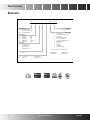
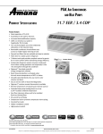
PTAC Air Conditioners and Heat Pumps 11.7 EER / 3.4 COP P roduct S pecifications Product Features • • • • • • • • • • • • • • • • • • • • • • • Quiet operation: STC of 28 Assembled in the USA for 30 years Increased dehumidification capacity 100% run-tested at our plant in Fayetteville, TN, for leaks 7⅝” unit front depth: one of the shallowest silhouettes in the industry today Removable condenser shroud allows easy access to enable regular cleaning of coils Easy pull-out filters that are washable and easy to maintain Filter drier for sealed system refrigerant 7-Button touch pad provides complete control to guests for in-room comfort while maintaining energy efficiency Condensate dispersion system removes condensate from indoor cooling operation and evaporates it into the atmosphere through the condenser Digismart™ front desk control & energy management software Room freeze protection is activated when the unit senses temperatures of 40°F or below Versatile style that blends into any room’s color scheme and decor Easy to service with on-board led diagnostics Digismart™ wireless remote thermostat is available Remote temperature sensing for guest climate control Extended heat pump heating down to as low as 24°F outdoor ambient temperature Zero floor clearance allows unit to be installed flush to a finished floor 30-second fan-off delay Compressor lock-in prevents compressor short-cycling Constant fan mode Hidden ventilation control High-pressure switch Control Board First-Year Warranty: Parts & Labor on entire unit Second through Fifth Year: Parts & Labor on certain sealed system components Second through Fifth Year: on certain functional parts only * Complete warranty details available at www.amana-ptac.com. SS-DPTAC www.amana-ptac.com Amana® is a trademark of Maytag Corporation or its related companies and used under license to Goodman Company, L.P., Houston, Texas. 2/13 Supersedes 9/12 Product Specifications Nomenclature PTC 07 3 G 35 1,2,3 4,5 6 7 8,9 AXXX AA 10,11,12,13 14,15 Basic Model Type PTC Standard Cooler PTAC PTH Standard Heat Pump PTHP DRY Dehumid Cooler PTAC Engineering Major & Minor Revisions A C D F H P Q R V X W Cooling Capacity 07 7000 BTU/h 60 Hz 09 9000 BTU/h 60 Hz 10 10000 BTU/h 50 Hz 12 12000 BTU/h 50 or 60 Hz 15 14000 BTU/h 60 Hz Rated Voltage 2 115V, 60 Hz, 1 Ph 3 230/208V, 60 Hz, 1 Ph 4 265V, 60 Hz, 1 Ph 5 240/220V, 50 Hz, 1 Ph Use up to 4 as needed in alphabe>cal order Examples: PTC123E50AXXX PTC073E35CRXX PTC123E50CXXX PTC073E25CQRW Design Series G R-‐410A Heater Size 00 No Electric Heat 15 1.5 kW 25 2.5 kW 2 Features Code Standard Model Corrosion Protec>on (Seacoast) Power Door Fuse Holder (230/208 Only) Hydronic Heat-‐Capable Condensate Pump (PTH Only) Quiet STC 31 Chassis RF Antenna Power Vent placeholder Hard-‐Wired (PTQC) 35 50 3.5 kW (230/208V) 3.7 kW (265V) 5.0 kW www.amana-ptac.com SS-DPTAC Product Specifications Product Specifications: PTC Models — Cooling/Electric Heat 230/208 Volts Model ⁶, ⁸, ⁹ Voltage ³ Capacity (BTU/h) PTC 073G***XXX PTC 093G***XXX PTC 123G***XXX PTC 153G***XXX 230 / 208 230 / 208 230 / 208 230 / 208 7,700 / 7,700 9,000 / 9,000 11,700 / 11,500 15,000 / 14,700 Amps ¹⁰ 3.5 / 3.5 4.1 / 4.1 5.6 / 5.6 7.0 / 7.0 Watts ¹⁰ 670/660 805/785 1135/1105 1500/1470 EER 11.5/11.7 11.2/11.5 10.3/10.4 10.0/10.0 4.2 4.9 6.8 8.5 High 290 290 290 340 Low 264 264 264 314 High 310 310 310 360 Low 282 282 282 332 Ventilated Air, CFM (Fan Only)* 65* 65* 65* 65* Dehumidification (Pints/Hr.) 1.7 2.2 3.6 4.4 Net Weight (lbs.) 98 102 102 113 Ship Weight (lbs.) 113 117 119 130 PTC 074G***XXX PTC 094G***XXX PTC 124G***XXX PTC 154G***XXX Unit without Electric Heater Min. Circuit Amps ², ⁴, ¹⁰ CFM (Cool/Wet Coil) CFM (Dry Coil) 265/277 Volts Model 1, 6, 8 Voltage ¹, ³ Capacity (BTU/h) Amps ¹⁰ 265 265 265 265 7,700 9,000 12,000 14,800 3.0 3.6 4.8 6.0 Watts ¹⁰ 670 795 1,165 1,480 EER 11.5 11.3 10.3 10.0 3.6 4.4 5.9 7.4 High 290 290 290 340 Low 264 264 264 314 High 310 310 310 360 Low Unit without Electric Heater Min. Circuit Amps ², ⁴, ¹⁰ CFM (Cool/Wet Coil) CFM (Dry Coil) 282 282 282 332 Ventilated Air, CFM (Fan Only)* 65* 65* 65* 65* Dehumidification (Pints/Hr.) 1.7 2.2 3.6 4.4 Net Weight (lbs.) 98 102 102 113 Ship Weight (lbs.) 113 117 119 130 * Approximately 95 CFM with optional power vent kit. Actual vent CFM performance will vary due to application and installation conditions. See Notes on following page. SS-DPTACwww.amana-ptac.com3 Product Specifications Product Specifications: PTC / PTH Models — Electric Heat Performance (Primary Heating for PTC Models; Auxiliary Heating for PTH Models; See below for Power Cord Configuration) Electric Heat (kW) No. of Stages 230/208V 2.5 230/208V 3.5 Voltage 230/208V Nominal Heating (BTU/h) Total Watts6 Total Amps Min. Circuit Ampacity² MOP4 (amps) Power Cord @ 230V @ 208V @ 265V 1 8,500 6,800 -- 2,570 / 2,115 11.2 / 10.1 14.0 15 6-15 P 1 12,000 9,900 -- 3,570 / 2,935 15.5 / 14.1 19.4 20 6-20 P 5 1 17,100 14,000 -- 5,070 / 4,160 22.1 / 20.0 27.5 30 6-30 P 265V 2.5 1 -- -- 8,500 2,570 9.7 12.1 15 7-20 P 265V 3.7 1 -- -- 12,600 3,770 14.2 17.8 20 7-20 P 265V 5 1 -- -- 17,100 5,070 19.2 23.9 25 7-30 P Notes ¹ All 265-volt models must use an Amana® brand sub-base (PTSB4**E) or an Amana® brand hard-wire kit PTPWHWK4 and disconnect switch PSHW04A. ² Minimum Circuit Ampacity (MCA) ratings conform to the National Electric Code; however, local codes should apply. ³ Minimum voltage on 230/208-volt models is 197 volts; maximum is 253 volts. Minimum voltage on 265-volt models is 239 volts; maximum is 292 volts. ⁴ Overcurrent protection for all units without electric heaters is 15 amps. Overcurrent protection on 265-volt models must be cartridge-style time-delay fuses (included and factory-installed on all Amana® brand 265-volt chassis). See heater performance ⁵ Heating capacity and efficiency based on unit operation without condensate pump; unit automatically switches to electric heat at approximately 24°F outdoor ambient. ⁶ Specify two-digit heater kW size to complete model number. ⁷ R-410A refrigerant used in all systems. ⁸ All units meet or exceed ASHRAE 90.1 standards. ⁹ All units less than 250 volts have a Leak Current Detector Interrupter (LCDI) power cord and meet UL 484 standards. ¹⁰ Refer to electric heat performance data for total MCA and recommended overcurrent protection. Amps and Watts notation refers to compressor only. 4 www.amana-ptac.comSS-DPTAC Product Specifications Product Specifications: PTH Models — Cooling/Heat Pump/Electric Heat 230208 Volts Model ⁶, ⁸, ⁹ Voltage ³ Capacity (BTU/h) Amps ¹⁰ PTH 073E**AXXX PTH 093E**AXXX PTH 123E**AXXX PTH 153E**AXXX 230 / 208 230 / 208 230 / 208 230 / 208 7,600 / 7,500 9,000 / 8,900 11,500 / 11,100 14,000 / 13,900 3.5 / 3.5 4.1 / 4.1 5.6 / 5.6 7.0 / 7.0 Watts ¹⁰ 650 / 620 770 / 765 1095 / 1065 1460 / 1465 EER 11.3 / 11.4 11.1 / 11.1 10.2 / 10.1 9.6 / 9.5 4.2 5.0 6.8 8.5 High 290 290 290 340 Low 264 264 264 314 High 310 310 310 360 Low 282 282 282 332 Ventilated Air, CFM (Fan Only)* 65* 65* 65* 65* Dehumidification (Pints/Hr.) 1.7 2.2 3.6 4.4 Net Weight (lbs.) 108 112 115 126 Ship Weight (lbs.) 123 127 132 143 PTH 074E**AXXX PTH 094E**AXXX PTH 124E**AXXX PTH 154E**AXXX 265 265 265 265 7,500 9,000 11,500 14,000 3.0 3.6 4.8 6.0 Unit without Electric Heater Min. Circuit Amps ², ⁴, ¹⁰ CFM (Cool/Wet Coil) CFM (Dry Coil) 265,277 Volts Model ¹, ⁶, ⁸ Voltage ¹, ³ Capacity (BTU/h) Amps ¹⁰ Watts ¹⁰ 635 780 1115 1430 EER 11.6 11.1 10.0 9.7 3.6 4.4 5.9 7.3 High 290 290 290 340 Low 264 264 264 314 High 310 310 310 360 Low 282 282 282 332 Ventilated Air, CFM (Fan Only)* 65* 65* 65* 65* Dehumidification (Pints/Hr.) 1.7 2.2 3.6 4.4 Net Weight (lbs.) 108 112 115 125 Ship Weight (lbs.) 123 127 132 142 Unit without Electric Heater Min. Circuit Amps ², ⁴, ¹⁰ CFM (Cool/Wet Coil) CFM (Dry Coil) * Approximately 95 CFM with optional power vent kit. Actual vent CFM performance will vary due to application and installation conditions. See Notes on previous page SS-DPTACwww.amana-ptac.com5 Product Specifications Product Specifications: PTH Models — Reverse-Cycle Heating Performance 230/208 Volts PTH 073E**AXXX PTH 093E**AXXX PTH 123E**AXXX PTH 153E**AXXX Voltage ³ 230 / 208 230 / 208 230 / 208 230 / 208 BTU/h ⁵ 6,800 / 6,800 8,300 / 8,100 10,900 / 10,500 13,500 / 13,300 Amps ¹⁰ 3.5 / 3.5 4.1 / 4.1 5.6 / 5.6 7.0 / 7.0 Watts ¹⁰ 605 / 605 735 / 720 1040 /1020 1365 / 1345 COP5 3.3 / 3.3 3.3 / 3.3 3.1 / 3.1 2.9 / 2.9 310 310 310 360 PTH 074E**AXXX PTH 094E**AXXX PTH 124E**AXXX PTH 154E**AXXX Voltage ³ 265 265 265 265 BTU/h ⁵ 6,800 8,200 11,000 13,500 Amps ¹⁰ 3.0 3.6 4.8 6.0 Heating Capacity CFM (Dry) 265/277 Volts Heating Capacity Watts ¹⁰ 585 730 1040 1365 COP ⁵ 3.4 3.3 3.1 2.9 CFM (Dry) 310 310 310 360 COP = Coefficiency of Performance; per ARI test procedures, units are rated for capacities and efficiencies. Notes: ¹ All 265-volt models must use an Amana® brand sub-base (PTSB4**E) or an Amana® brand hard-wire kit (PTPWHWK4). ² Minimum Circuit Ampacity (MCA) ratings conform to the National Electric Code; however, local codes should apply. ³ Minimum voltage on 230/208-volt models is 197 volts; maximum is 253 volts. Minimum voltage on 265-volt models is 238.5 volts; maximum is 291.5 volts. ⁴ Overcurrent protection for all units without electric heaters is 15 amps. Overcurrent protection on 265-volt models must be cartridge-style time-delay fuses (included and factory-installed on all Amana® brand 265-volt chassis). See heater performance for total MCA. ⁵ Heating capacity and efficiency based on unit operation without condensate pump; unit automatically switches to electric heat at approximately 24°F outdoor ambient. ⁶ Total watts for 12,000 and 15,000 BTU/h models; subtract 70 watts for PT07/09*E**A* ⁷ Specify two-digit heater kW size to complete model number. ⁸ Total amps for 12,000 and 15,000 BTU/h models; subtract 0.2 amps for PT07/09*E*A*. ⁹ R-410A refrigerant used in all systems. ¹⁰ All units meet or exceed ASHRAE 90.1 standards. ¹¹ All units less than 250 volts have a Leak Current Detector Interrupter (LCDI) power cord and meet UL 484 standards. ¹² Refer to electric heat performance data for total MCA and recommended overcurrent protection. Amps and Watts notation refers to compressor only. 6 www.amana-ptac.comSS-DPTAC Product Specifications Contractor's Bid Sheet Furnish and install air-cooled through-the-wall package terminal air conditioners amd heat pumps (assembled in the USA). Units are rated in accordance with the ARI (Air Conditioning & Refrigeration Institute) Standards 310/380-93, CSA (Canadian Standards Association) EEV certification programs and listed by U. L. (Underwriters Laboratories). Ratings Each unit must meet the following specifications: ARI rating of _________BTUH cooling (and _________ BTUH reverse cycle heating with a COP of _________ at 47° F O.D.) Electric resistance heat of _________ BTUH. Total Amp draw must be of ________ and _________ Watts at _________ volts. The unit must remove a minimum of _________ pints of moisture per hour when operated at rating conditions. The EER must be a minimum of _________ EER. Unit Chassis Each unit must be slide out design shipped with room cabinet front installed. Unit chassis must have the ability to be installed with 0 clearance from finished floor. An electrical power cord must be included with chassis and installed by the manufacturer to assure proper NEMA 6 or 7 configuration and UL-approved length. Units less than 250 volts must also have a LCDI power cord. Unit must be tested for conformance to ASTME water infiltration specification ASTME 331-86, which ensures no water infiltration when tested at 8" rain per hour at 63 mph wind for 15 minutes. Room Cabinet The monochromatic front of the room cabinet must be able to be field-secured to chassis to inhibit tampering. Filter must be accessible without removing room front. Cabinet depth must not exceed 7⅝” to minimize unit’s impact on room space. Coils Unit’s coils must have rifled copper tubing expanded into rippled-edge louvered aluminum fins. Exterior coil must be of a two-row bent coil design with removable shroud top to allow easy-access for cleaning of the exterior coil. Heat Pumps Each unit must include a change-over thermistor that senses an outside ambient switch-over temperature as low as 24°F, lockopen refrigerant reversing valve during heat pump operation, temperature-activated defrost drain and automatic emergency heat operation to override the heat pump’s change-over thermostat and bring on electric resistance heaters in the event of a sealed system failure. Unit must not operate compressor and electric heaters simultaneously. Compressor Unit Digital Controls The unit’s control must be completely wired and accessible from the top of the chassis. Controls shall be a LED touch-pad design with seven large, easy-to-read and use buttons: Heat – Cool – Off – Fan – Temp+ (plus) – Temp- (minus) and two red sevensegment LED temperature displays. Unit shall have a green status LED to advise owner of operational diagnostic messages. Unit shall have one-button activation via membrane touch-pad. Unit control board shall have an 18-pin low-voltage connector to allow for easy connection to remote wired devices. Unit shall have two serial-port connectors for easy connection to wired or wireless EMS (Energy Management Systems). Unit must have the ability to easily configure owner-selectable and programmable functions: • Fan-cycle operation • Electronic temperature limiting for cooling • Electronic temperature limiting for heating • Enhanced dehumidification cooling operation • Unoccupied 18-hour temperature set-back • Un-rented temperature set-back • Multiple unit twinning to one wired thermostat • Load-shedding operation • Front-desk on-off or temperature set-back Unit must be able to connect to approved remote devices: • Wired thermostat • Wired door motion sensor • Wired room motion sensor • Wired room-to-room transfer fan • Front Desk Control • Future RF wireless communications devices Unit must be able to acquire and display operational temperature data from up to six installed thermistors to include: • IAT—Indoor air temperature (black) • ICT—Indoor coil temperature (red ) • IDT—Indoor discharge temperature (yellow) • OCT—Outdoor coil temperature (blue) (heat pumps & Wireless cooler models) • OAT— Outdoor Air Temperature (Wireless-ready models only) • Orange—Miscellaneous thermistor or analog device (optional) Evaporator/Condenser Fans The compressor must be hermetically sealed, internally isolated, rotary-type and permanently mounted on rubber isolators. No removal or adjustment of compressor hold-down bolts is to be required during installation. Direct drive with a permanent, split-capacitor, two-speed indoor motor. Condensate must be directed onto the back and sides of the coil to aid in evaporation and removal. Warranty Must be a sloped surface so that obstructions cannot be placed on the unit. Discharge conditioned air can be directed into the room at an angle of 16 or 56 degrees from the vertical position. The discharge grille must be of polycarbonate material to resist bending, cracking, rusting and corrosion. The warranty is for Full One Year on the entire unit; Full 2nd through 5th Year on the entire sealed refrigerant system components; Limited Second through Fifth Year on functional parts only. Air Discharge SS-DPTACwww.amana-ptac.com7 Product Specifications New installations typically require a minimum of WS900D wall sleeve and an outdoor grille. Wall Sleeves (WS900E) The wall sleeve must be industry-accepted dimensions: 14⅛” depth x 42” width x 16¹/₁₆” height and constructed of G90 HDG galvanized steel with a baked corrosion-inhibiting urethane primer and baked-polyester topcoat enamel. Sleeve must be insulated and shipped with a weather resistant rear closure panel installed. Outdoor Grilles Outdoor grille must be architecturally extruded, louvered aluminum (AGK01*B), one-piece polymer-blend injection molded louver (PGK01*B) or standard stamped aluminum (SGK**B). All other grilles must be submitted to the PTAC manufacturer for feasibility, airflow characteristics and compliance with UL regulations, where necessary. The optional accessories listed below perform specific functions required in some installations. Condensate Drain Kit (DK900D) Duct Kits (MDK01E, EDK02B, TDK02B, PTDK01E, DDK01E) Subbase Kit (PTSB***E) Hydronic Heat Kit Attaches to the bottom of the wall sleeve for directionalcontrolled internal or external disposal of condensate, defrost or rain water. Necessary for UL listing requirements for 265V units (Hard Wire Kit may be substituted for Subbase kit). Optional for 230/208V units. Must be pre-wired to facilitate field-electrical connections and include an NEMA 6 or 7 configuration electrical receptacle. It must have two leveling screws for sleeve support and accurate unit leveling during installation. Locations for field installation of physical disconnect switches, cartridge-style fuse holders and circuit breakers must be provided. Side-skirts must be provided with subbases. (PTSB000E Non-Electrical Subbase available.) Three kits must be supplied to provide ducted, conditioned air into a second room: a main duct kit, an extension duct kit and a terminal duct kit. Is required for heating functions instead of electric resistance heaters. Unit must retain complete service access with the kit installed. Proper water or steam valves must be used. Condensate Removal Pump (Heat Pumps only) Must be installed to assist in removing the condensate developed by the heat pump operation and transfer it to the indoor coil to dissipate into the room, adding humidity to the room. Circuit Breaker Kit Power Vent & Damper Must be provided to maximize ventilation air intake to up to approximately 95 CFM. Power vent must be off and damper door closed when unit fan is de-energized. Must be installed in subbase to provide overcurrent protection for proper 230/208V amperage. Can also be used as a physical disconnect where local codes permit for 230/208 voltage. Fuse Holder (included in 265V chassis) Hard Wire Kit Must be installed either in the unit or the subbase and must match the electrical requirements of the chassis. Security Key Locks (KL03E) Must be installed to prevent tampering of the unit controls. Unit room cabinet must also be secured to the chassis with field supplied screws. UL-approved for institutional use only. Disconnect Switch Power disconnect switch must be installed in subbase for use as a physical disconnect, where required by local codes. Must be used to permanently wire chassis for hard wire purposes. (For 265V units, Hard Wire Kit may be substituted with Subbase Kit.) Thermostats A manufacturer-approved manual, auto changeover or programmable traditionally wired thermostat must be installed to provide full remote operation of the chassis. A Remote Escutcheon Kit must be used to indicate remote operation. Amana® is a trademark of Maytag Corporation or its related companies and used under license to Goodman Company, L.P. All rights reserved. Our continuing commitment to quality products may mean a change in specifications without notice. © 2013 • Goodman Company, L.P. • Houston, Texas • Printed in the USA. 8 www.amana-ptac.com SS-DPTAC