1
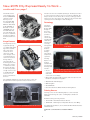
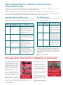
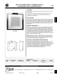
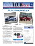
January 2015, Volume 17, No. 1 New 2015 City Express Ready to Work The all-new 2015 Chevrolet City Express small cargo van is a small Euro-style work van designed for businesses that need to move cargo but do not need the capabilities of a full-size van. It’s offered in LS and LT trims. The van is equipped with a 2.0L inline-4 cylinder DOHC engine and front wheel drive via a continuously variable transmission (CVT). The front suspension features MacPherson struts with coil-over springs, twin-tube dampers and a stabilizer bar. The solid axle rear suspension has twintube shock absorbers and truck-style multi-leaf springs. Electric power steering provides a tight turning diameter of only 36.7 feet (11.2 meters). Powertrain The 2.0L inline-4 Cylinder, DOHC gasoline engine (RPO L0A) features continuously variable valve timing engine, sequential multi-port fuel injection and a cast aluminum engine block and cylinder heads. The engine is rated at 131 hp (98 kW) at 5,200 rpm and 139 lb.-ft. (188 Nm) of torque at 4,900 rpm. continued on page 2 CONTENTS TECHLINEnews Service Information Links Added Quick Access to Maintenance Items and Maintenance Replacement Parts Convenient links to maintenance items and maintenance replacement parts have been added to the Service Information for the 2012-2016 model years. These links put common maintenance resources all in one easy-to-find location. TIP: The Maintenance Items chart and Maintenance Replacement Parts document can be found after building the desired model and then selecting Service Manual > General Information > Maintenance and Lubrication > Specifications. Or users can keyword search for maintenance items or maintenance replacement parts. continued on page 3 New 2015 City Express. . . . . . . . . . . . . . . . . . . . . . . . 1 Service Information Links Added. . . . . . . . . . . . . . . . . 1 Transmission Technical Guides. . . . . . . . . . . . . . . . . . 3 Download PDI Forms. . . . . . . . . . . . . . . . . . . . . . . . . . 3 False Side Blind Zone Alert. . . . . . . . . . . . . . . . . . . . . 4 Unable to Learn Tire Pressure Monitor. . . . . . . . . . . . 4 Grease on the Torque Converter Housing. . . . . . . . . . 4 Engine Tick Sound Heard Inside Cab. . . . . . . . . . . . . 4 Radio Backlighting Stays On. . . . . . . . . . . . . . . . . . . . 5 ASE Now Offers Year-Round Testing. . . . . . . . . . . . . 5 Update Tech2Win for Latest Diagnostics. . . . . . . . . . 6 New Categories for CCND Codes. . . . . . . . . . . . . . . 7 Oil Leak after the Harmonic Balancer is Removed . . . 7 Hood Bumpers and Latch Adjustment. . . . . . . . . . . . . 8 Squeak Sound from HUD Area. . . . . . . . . . . . . . . . . . 9 New Training Courses. . . . . . . . . . . . . . . . . . . . . . . . . 9 Bulletin Review . . . . . . . . . . . . . . . . . . . . . . . . . . . . . 10 Service Know-How . . . . . . . . . . . . . . . . . . . . . . . . . . 10 Customer Care and Aftersales New 2015 City Express Ready to Work – continued from page 1 The CVT8 continuously variable transmission (RPO MRA) optimizes torque delivery across the rpm band. GM recommends using ACDelco CVT Fluid, P/N 19260800 (in Canada, use P/N 19299096). Do not mix CVT fluid with any other fluids and do not use automatic transmission fluid or manual transmission fluid. Cargo Features The City Express has a payload capacity of 1,500 pounds (680 kg) and a customizable cargo space volume of 122.7 cubic feet (3,474 liters). Cargo can be secured with the six steel floor-mounted D-rings with reinforced weld nut mounting points. The 54.8 inches of space (1.39 meters) at the floor from side wall to side wall provides enough room to load a standard 40 x 48 inch (1.01 x 1.22 meters) pallet flat on the floor. The tall rear doors are a 40/60-split design. The 60-percent door is on the passenger side for easy access from the sidewalk. The 40-percent door on the driver side is shorter, reducing potential intrusion into the street when open. Both rear doors feature dual opening positions of 90 degrees and 180 degrees. Technology The Driver Information Center (DIC) display on the instrument cluster provides a variety of vehicle data, including trip odometers, instant fuel economy, average fuel economy, distance to empty mileage and outside temperature (optional). 2.0L inline-4 cylinder engine The DIC offers a variety of vehicle information to the driver. The City Express LT model is available with a Technology Package that includes: The Technology Package includes a color • A color connected radio and Rear Vision Camera display. connected radio with color touch screen display CVT8 continuously variable transmission • Bluetooth® streaming audio for music and select phones and hands-free smartphone integration The standard sliding doors on both sides of the vehicle are designed for low effort operation and convenient access. • AM/FM radio with CD player • GPS navigation • SiriusXM Radio • Rear Vision Camera (RVC) with Rear Parking Assist. Training Courses Training courses for the 2015 City Express can be found at www.centerlearning.com (U.S.) or www.gmprocanada.com (Canada). Available training currently includes: • 10214.14W – New Model Features Course • 16440.19D – New Engines and Updates Course (U.S. Only) For additional information, refer to #PI1362: New Model Features and Information. The 40/60 rear doors offer less potential intrusion into the street Thanks to Sherman Dixon and Calvin William 2 January 2015 TECHLINEnews Transmission Technical Guide PDFs Now Available Service Information Links Added – The GM Service Information recently added Transmission Technical Guides for many transmissions. The guides are available on the Service Information home page in a printerfriendly PDF format. From the Service Information home page, select the link for Unit Repair, Specialty Publication or Transmission Technical Guide. continued from page 1 The new chart provides fast navigation to maintenance-related procedures and information, including approximate fluid capacities, resetting the GM Oil Life System, tire pressure indicator sensor learn, passenger compartment air filter replacement, and spark plug replacement. This information is currently located in various sections of the Service Information as well. By linking the information in the new chart, it reduces the amount of navigation required to view the different maintenance procedures and information. Available Transmission Technical Guides The right side of the page lists the Supplemental Transmission Technical Guides. Since the guides are rather large, it may take 30 seconds or so to open each PDF. Thanks to Lisa Scott Download PDI Forms from the Service Information Maintenance Items chart Pre-Delivery Inspection (PDI) forms can now be downloaded from the Service Information. In addition, for North American models, the Maintenance Replacement Parts document provides part numbers for common maintenance items, similar to what is found in the owner manuals. It lists parts such as the engine air cleaner/filter, engine oil filter, spark plugs and wiper blades. To access the PDI forms: 1. Select a late model from the drop-down menu or enter the full VIN and select “Next.” 2. PDI forms are located at the bottom of the “Select a vehicle publication to view” page Once opened, the form performs as if it was retrieved from GlobalConnect. The form can be filled out online, but data typed into the form cannot be saved. If there is an additional Special Inspection Items page that applies to PDI forms have been added to the Service the vehicle, it will Information. be included with the PDI form. Both forms can be printed. Maintenance Replacement Parts document Thanks to Mike Adamczyk Thanks to Lisa Scott January 2015 3 False Side Blind Zone Alert The Side Blind Zone Alert system may become active with no objects within range of sensors on some 2014 LaCrosse and Malibu models equipped with Obstacle Detection Side Active Safety (RPO UKC or UFT). If this occurs no DTCs will be stored. The side blind zone alert system uses two side object sensor modules to notify the driver that an object is present in one of the driver’s side blind zones. An icon on the left or right side view mirror is illuminated when an object is detected. The side object sensor modules are located on each side of the vehicle behind the rear fascia If false side blind zone alerts occur, inspect the rear bumper fascia for signs of damage. If no fascia damage is found, reprogram the B2181L Side Object Sensor Module. Refer to B2181L Side Object Sensor Module Programming and Setup in the appropriate Service Information. TIP: Remind owners that if the vehicle is towing a trailer or has an object such as a bicycle rack attached to the rear of the vehicle, the Side Blind Zone Alert system may not function properly and the indicators may illuminate intermittently or remain illuminated all the time. Thanks to David Roat Unable To Learn Tire Pressure Monitor after Tire Service After performing a tire service (rotation) on some 20072012 Malibus, the vehicle may go into tire pressure indicator sensor learn mode but not respond to a sensor or sensors that have been activated with the Tire Pressure Monitor (TPM) tool (either EL-46079 Tire Pressure M onitor Diagnostic Tool or EL-50448 Tire Pressure Monitor Sensor Activation Tool). Remove the B+ fuse for the OnStar Vehicle Communication Interface Module (VCIM). For fuse location, refer to the appropriate Service Information for the vehicle being serviced. If it is now possible to complete the TPM learn, complete the procedure and then reinstall fuse. TIP: If an obvious fault or concern is present with OnStar and the account is active, proceed with normal d iagnostics according to the appropriate Service Information. Thanks to Christopher Crumb Grease on the Torque Converter Housing Engine Tick Sound Heard Inside Cab On some 2015 Colorado and Canyon models equipped with an automatic transmission (RPO MYB), what appears to be an oil drip may be found on the inspection plug on the bottom of the torque converter housing or the crossmember. An engine or High Pressure Fuel Pump tick sound may be heard inside the cab of some 2015 Colorado and Canyon models equipped with the 3.6L V6 engine (RPO LFX) that were built prior to October 29, 2014. Comparisons with other trucks with the same powertrain may show the other trucks to be quieter. TIP: A tick noise of this type is a normal characteristic of direct injection engines. Refer to Bulletin #07-06-04-025 for additional information about direct injection fuel system operation. On trucks built prior to October 29, 2014, an acoustic seal may have been knocked out of place during assembly. If this acoustic seal is dislodged or missing, the High Pressure Fuel pump tick sound can be heard easily inside the cab of the truck. Inspection plug on the bottom of the torque converter. Remove the inspection plug with a pick tool and inspect the fluid on it. If the seal is missing, replace it with one from Kit Part Number 23135690. Reference the Blower Upper Case Replacement section of the appropriate Service Information to assist with seal replacement. The fluid may be grease from the assembly of the transmission to the engine that has migrated to Inspect any fluid on the plug. the bottom of the torque converter housing. The fluid will be much thicker than oil. Seal missing Thanks to Jeremy Richardson If grease is found, clean out the inspection hole and plug with degreaser and reinstall the plug. Clean any other affected surfaces. Seal present Thanks to Kenneth Cole 4 January 2015 Radio Backlighting Stays On On some 2014 Silverado 1500 and Sierra 1500 and 2015 Silverado and Sierra models equipped with transfer case RPO NQF or NQH, the radio backlighting may stay on after the ignition has been turned off and the key has been removed for several minutes. Eventually, the battery will go dead. Some solenoids/relays may only have a positive post and will get their ground through the mounting bracket. In this case, the striped end of the diode is to be connected to the positive terminal and other end should be connected to the ground of the solenoid/relay. While diagnosing this condition, voltage may be present at the following fuses with the ignition key in the Off position: F23DL, F22DL, F30DL, F31DL, F32DL. These fuses are all on the same Run/Crank Ignition Buss Bar, in the Left I/P Fuse Block, and should not have any power with the ignition off. In some cases, there may only be 2 or 3 volts present. Use a voltmeter to check for voltage. This condition may be caused by the Transfer Case Control Module (TCCM) back feeding voltage into the fuse block with the ignition off. If the TCCM is disconnected, the voltage at the fuses will be gone. If the TCCM is replaced, the issue may only be corrected for a short time. The internal circuitry of the TCCM may have been permanently damaged by a voltage spike, causing the back feed. In most cases, the voltage spike is caused by an aftermarket accessory, which uses a solenoid or relay, that is wired onto the F30DL fuse or to the X61A I/P Junction Block connector X7, terminal 11, or connector X5, terminal 35. If these solenoids or relays are not properly suppressed, they will produce a voltage spike. The voltage spike can be transmitted onto the Run/Crank Ignition Buss Bar and permanently damage the TCCM. TIP: Do not replace the TCCM until the root cause of the condition has been narrowed to the solenoid/relay voltage spikes. To prevent damage to any of the sensitive electronic components on the bussed circuit, the solenoid/relay must have the control circuit suppressed with a diode. The diode will prevent the voltage spikes from being transmitted onto the Run/Crank Install a diode to prevent voltage spikes. circuit. Install a diode, P/N 12112422, across the coil of the solenoid. Connect the striped end of the diode to the positive terminal of the coil and connect the other end of the diode to ground. Be sure to insulate the diode with heat shrink tubing before installation. Insulate the diode with heat shrink tubing before installation. Also install a diode, P/N 12112422, across the coil of the relay. Connect the striped end of the diode to the positive terminal of the coil and connect the other end of the diode to ground. Be sure to insulate the diode with heat shrink tubing before installation. Solenoid/relay with only a positive post. This repair will not be covered under warranty due to the failure being caused by an aftermarket accessory. Thanks to Jim Will ASE Now Offers Year-Round Testing Automotive Service Excellence (ASE) has recently announced that testing is now available 12 months of the year. After technicians register for testing during one of the four registration windows, they will always have 90 days to schedule an appointment and take the test. This means that whether you register on the first day of registration or the last day, you will have 90 days from that date of registration to complete the test. Besides being more convenient, the yearround testing should help reduce the January 2015 amount of last-minute testing taken at the end of previous testing periods. There will continue to be four testing periods — winter, spring, summer and fall — throughout the year. ASE Test Centers ASE tests are conducted at more than 450 Prometric test centers across the country. Go to www.ase.com to find a local test center and to see what to expect at an ASE test center when taking an ASE computer-based test 5 Winter Registration December 1, 2014–February 20, 2015 Register using the myASE LOGIN at www.ase.com or call Prometric at 1-877-346-9327. Winter Testing Begins December 1, 2014 and runs continuously Thanks to Mike Durkin Update Tech2Win for Latest Diagnostics The Tech2Win application first released to GM dealerships in 2011 is a version of the Tech 2 and CANdi (Controller Area Network diagnostic interface) module loaded onto a Techline PC or laptop computer via TIS2Web. Technicians can take advantage of the computing power of their PC or laptop computer as well as the speed of the MDI — when using Tech2Win, vehicle communication is performed using the Multiple Diagnostic Interface (MDI) — for faster operation, more convenience and added diagnostic capabilities. 4. To initiate the software license and install the diagnostic software, select the Software Download (SWDL) on TIS2Web and click Start Software Download. Using it on a PC or laptop computer that also has GDS 2 installed provides all diagnostic tools on one computer. Plus, with a laptop computer, Tech2Win can be used during a vehicle road test, offering a larger screen with all of the Tech 2 tool capabilities. Tech2Win also supports touch screen functionality. After the download is complete, the license countdown in the lower right corner will be updated to 30. Select Tech 2 and Custom for the update mode. This is the number of days until the license must be renewed. When the license expires, an expiration message will be displayed. To renew the Select the desired diagnostic software package. license, use the security access service or update the diagnostic software using the standard update mode. 5. Select Tech2 and Custom for the update mode. 6. Select the desired diagnostic software package. 7. Click Download to begin downloading the diagnostic package. Current progress and Tech2Win will display during the download. Tech2Win Features The Tech2Win application offers most of the features and functions of the Tech 2. Tech2Win: • Is used for diagnostics only. Service programming is still performed through TIS2Web SPS. • Requires a license that must be updated every 30 days, similar to the license renewal of GDS 2. • Requires PC and laptop computer specifications that meet or exceed the current minimum Techline hardware specifications. Review the latest specifications and guidelines at www.gmdesolutions.com. (In Canada, the IT guidelines are in the Service Library under Tools, Processes and Equipment on Global Connect.) Access for All The Tech2Win application does not require any special access or other tools or software. When selecting the Tech 2 software download on TIS2Web, a prompt will ask if you want to install Tech2Win. After installing the Tech2Win application, a software download also will be required to download the desired diagnostic software for the desired vehicle coverage. Tech2Win uses Communication Port (comm port) 9 on the PC. If this port is used for other devices, switch the comm port setting by selecting the Tech2Win Configurator icon on the desktop. Refer to the Quick Reference Guide for complete details. Installing the Tech2Win Application To install the application: 1. Connect the MDI to the computer. Power it using the AC adapter. When using Tech2Win, you can click the selections on screen or click the soft buttons on the screen where applicable. 2. Select the Tech 2 software download on TIS2Web. A prompt will ask if you want to install Tech2Win. It can be installed on multiple PCs in the dealership. 3. Install the Tech2Win application using all the default selections. Installation should take less than 10 minutes. 4. Two icons will be placed on the PC desktop — a shortcut for Tech2Win QuickStart and a shortcut for the Tech2Win Configurator, which is used for multiple versions of Tech2Win depending on the vehicles being serviced in the dealership. Tech2Win activity is shown on the bottom of the screen between the vehicle, MDI, Tech2Win and the PC. After the application installation is complete, the diagnostic software for the desired service coverage and software license must be obtained. To download: Tech2Win activity is shown between the vehicle, MDI, Tech2Win and the PC To access the Quick Reference Guide for additional Tech2Win installation information, go to TIS2Web News and select the Tech2Win Quick Reference Guide. 1. Click the Tech2Win QuickStart icon that is now on the PC’s desktop. 2. Since Tech2Win does not have a current license, a license dialog box will appear. Click OK. Thanks to Chris Henley 3. When the MDI is detected, a dialogue box will direct you to select the vehicle communication interface. 6 January 2015 New Categories for Customer Concern Not Duplicated Codes The Customer Concern Not Duplicated (CCND) labor codes have been updated with new categories as of December 1, 2014.The new categories cover areas of the vehicles not previously covered by CCND labor codes. In addition, updates have been made to the Body/Electrical categories to remove duplicate titles for different labor codes. Be sure to use the appropriate CCND labor code based upon the customer concern. The correct codes help the related GM engineering team to more quickly identify trends that can be addressed with product improvements and/or bulletins. Updated Body/Electrical CCND Categories New CCND Categories Following are the updated Body/Electrical categories, the specific labor code and an example of a customer concern. Keep in mind that multiple systems or features may fall under the same labor code. Following are new CCND categories to cover previously undocumented vehicle areas. Code Code 6429919 Body/Electrical Category Electronics/Safety/ Object Detection New Category Example Example 1049929 Customer states the Lane Departure Warning Indicator illuminates when going around a corner. Followed SI diagnostics for Lane Departure Warning System Malfunction and was unable to duplicate the customer concern. Interior Buzz/ Squeak/Rattle Customer states there is rattle from the driver door when it is closed. Performed related system verification procedure in SI with no trouble found and unable to duplicate concern. 0559929 Air/Wind Noise Customer states there is a wind noise from the windshield area. Performed related system verification procedure in SI with no trouble found and unable to duplicate concern. 0569929 Water Leaks Customer stated water was leaking from the sunroof area, followed SI diagnostics for water leaks and was unable to duplicate the customer concern. 6459939 Electronics/Airbags Customer states SIR light has come on but is now off. Performed related system verification procedure in SI with no trouble found and unable to duplicate concern. 2069939 Keyless Entry/Theft Alarm/Memory Seats/ Lighting/Power Windows Customer states the keyless entry transmitter does not operate. Performed related system verification procedure in SI with no trouble found and unable to duplicate concern. 7029929 Seat Heating and Cooling/Hardware, Trim and Upholstery/Power Seat Customer states the driver front seat heater will not warm up. Performed related Front Heated Seat Malfunction procedure in SI with no trouble found and unable to duplicate the complaint. All labor codes, including CCND codes, can be found in the Labor Time Guides in the Service Information. Use the drop-down menus to build the desired model to view the applicable Labor Time Guide. For a complete list of CCND labor codes, refer to the latest version of Bulletin #06-00-89-026. Thanks to Bob Wittmann Oil Leak after the Harmonic Balancer is Removed There may be an oil leak condition after the harmonic balancer is removed or replaced on some 2015 Escalade models, 2014-2015 Silverado 1500, Suburban, Tahoe, Sierra 1500, Yukon models and 2014 Corvette, equipped with the 4.3L, 5.3L or 6.2L engine (RPOs L83 L86 LT1 LV3). seal the harmonic balancer to the crank. When reinstalling the harmonic balancer, a different bolt design may have been used than what was removed from the engine. If a Gen 4 bolt is used in a Gen5 engine, it will result in an oil leak. Gen 5 engines use a keyed harmonic balancer that can see oil pressure. It uses both a 1 piece bolt and a 2 piece bolt and washer arrangement. It seals to the face of the crank. Bolt 1– Gen 5 engine Bolt 2 – Gen 5 engine Bolt 3 – Gen 4 engine Gen 4 engines use a non-keyed harmonic balancer. The only part of the crank that is keyed drives the oil pump. The bolt has a friction material on the face. It does not January 2015 TIP: The LT1 engine dry sump uses a longer bolt due to the oil pump that is used on this system. Thanks to Richard Renshaw 7 Bolt 1 – 1 piece Gen 4 bolt measures 1.869 in. (47.5 mm) at the flange Bolt 2 – 1 piece Gen 5 Bolt measures 2.055 in. (52.2 mm) at the flange Hood Bumpers and Latch Adjustment The hood of a 2015 Colorado or Canyon may shake or flutter while driving due to misadjusted hood bumpers or the hood latch. After lowering the hood latch, lower the two inner bumpers (one on each side of the latch) by 1/4 to 1/2 turn clockwise. Repeat until the closing effort of the hood is a cceptable. Use a piece of paper to check for proper contact of the outer and middle bumpers to the hood. The paper must not pull free when the hood is closed. Perform the paper test on the inner bumpers after latch adjustment. There should be very little to no drag to remove the paper. Sound Deadener TIP: Do not place the paper over the headlamp. For the outboard bumpers, place the paper to the side of the headlamp and pull it over the fender. For the middle bumpers, place the paper to the front of the truck and pull it forward. If the paper cannot be pulled loose, the bumpers and latch are in adjustment. Apply Kent® Ure-Foam Expandable Foam Sound Deadener or equivalent in two locations (one per side). Apply the foam sound deadener in two locations (one per side). Remove the hood insulator, if applicable, and inject foam into the second hole from the side. Aim the applicator nozzle straight to the back and begin to fill the cavity. Once half of the product has been dispensed, tilt the tip upward and slowly draw the applicator back as the last half of the foam is injected, ensuring the product is applied to the hood panel. Remove any excess foam that prevents the hood insulator from installing into the outer hole. Check for proper contact of the outer and middle bumpers to the hood. Bumper and Latch Adjustment If the paper can be pulled loose, the bumpers and latch are not properly adjusted. It will be necessary to raise the outer and middle hood bumpers (2 per side) until the hood is flush with the fenders. Set the height of the bumpers to 22 mm off of the bracket surface and repeat the paper test. The following illustration shows a cross-section of the hood assembly. Apply the first half of the product in area 2. Apply the second half of the product in area 3. Apply the first half of the product in area 2 and the second half of the product in area 3. TIP: The Kent Ure-Foam Expandable Foam Sound Deadener takes up to three days to fully cure. Advise the customer that it may take up to three days before the maximum benefits of the sound deadener are realized. A. Outer and middle hood bumpers (2 per side) B. Inner bumpers (one on each side of the latch) Repeat the application of the sound deadener on the other side of the hood and reinstall the hood insulator. If there is not enough contact and the hood is flush to the fenders, temporarily mark the position of the hood latch and use a 13 mm ratchet or wrench to loosen the hood latch bolts just enough so that the latch will move but is not completely free. Refer to #PIT5340 for additional information and part numbers. Thanks to Jeremy Richardson Lightly tap the hood latch to lower it straight down 1 mm (do not move it left or right) and retighten to 22 Nm (16 lb.-ft.) with a torque wrench. 8 January 2015 Squeak Sound from HUD Area GM TechLink is published for all GM retail technicians and service consultants to provide timely information to help increase knowledge about GM products and improve the performance of the service department. On some 2015 Escalade and Yukon models equipped with a Head-Up Display (RPO UV6), a squeak sound may be heard at the top left side of the instrument panel while driving. The sound may be duplicated while the vehicle is parked by applying pressure up and down on the steering wheel. Do not use the tilt steering wheel feature to try to duplicate the sound. It also may seem that the sound is coming from behind the instrument cluster. Publisher: John Meade GM Customer Care and Aftersales Editor: Lisa G. Scott GM Customer Care and Aftersales Technical Editor: Mark Spencer / [email protected] Production Manager: Marie Meredith Graphic Design: 5by5 Design LLC / [email protected] Four areas of HUD shroud with felt tape. Felt tape applied to the full perimeter of the HUD shroud. The sound may be caused by the Head-Up Display (HUD) lens rubbing on the HUD shroud. The HUD shroud is part of the upper instrument panel extension. The HUD shroud may have four areas with felt tape installed, which is inadequate to eliminate the squeak sound. To eliminate the squeak sound, add 1 mm-thick felt tape, obtained locally, to the full perimeter of the HUD shroud. Thanks to Jim Will Write to: Service Technical College – New Training Courses PO Box 500 Troy, MI 48007-0500 Following are the latest service technical courses available to technicians through the GM Service Technical College. GM TechLink on the Web: For more information about available service training courses, log in to the GM Center of Learning at www.centerlearning.com and click the Catalog link. Use the drop-down menus to search for courses by delivery type, audience, and category. FAX number: 3 1-248-729-4704 * TechLink : GM GlobalConnect General Motors service tips are intended for use by professional technicians, not a “do-it-yourselfer.” They are written to inform those technicians of conditions that may occur on some vehicles, or to provideinformation that could assist in the proper service of a vehicle. Properly trained technicians have the equipment, tools, safety instructions and know-how to do a job properly and safely. If a condition is described, do not assume that the information applies to your vehicle or that your vehicle will have that condition. See a General Motors dealer servicing your brand of General Motors vehicle for information on whether your vehicle may benefit from the information. Inclusion in this publication is not necessarily an endorsement of the individual or the company. Copyright© 2015 General Motors All rights reserved. Course Number Course Title Course Type Duration 10041.12W-R2 SI Overview WBT 1.5 hr 10214.14W 2015 City Express WBT 1 hr 10315.12W 2015 Chevrolet Trax Model Year Update WBT 1 hr 10315.89W 2015 Corvette Z06 New Model Launch WBT 2 hr 10315.92H 2015 Cadillac CTS Model Year Update ILT 2 days 10343.10H Turbocharger System Operation and Diagnosis ILT 0.5 day 16240.70W-R2 Bi-Fuel System Operation WBT 1.5 hr 16440.19D Engines: New and Updates VCT 2 hr 18410.00W Two-Mode Hybrid Diagnostic Exercise WBT 0.5 hr 18440.20D1-R2 GM Global Electrical Systems VCT 2 hr 18440.20D2-R2 GM Global Electrical Systems VCT 2 hr WBT – Web-Based Training; VCT – Virtual Classroom Training; HO/ILT – Hands-On/InstructorLed Training January 2015 9 Bulletin Review Bulletin Category Bulletin Number Subject Body Hardware and Trim 09-08-110-011C Front or Rear Door Lock Lever Bezel Loose or Detached (Replace Bezel) 2008-2011 Cadillac CTS, CTS-V Body Hardware and Trim Body Systems Body and Accessories General Information 10-08-110-001C Information on Proper Use of Floor Mats 2015 and Prior GM Passenger Cars and Trucks Body Systems Body and Accessories 03-08-48-006J Repair Information for Reconnection of Rear Window (Defroster) Contact or Tab 2000-2015 GM Passenger Cars and Trucks (Excluding 2015 Chevrolet Tahoe, Suburban, GMC Yukon and Cadillac Escalade) Driveline/Axle General Information 14-04-20-001A Moan from Rear Differential During Low Speed Tight Turn Maneuvers 2014-2015 Chevrolet Camaro Z/28 Engine Engine/Propulsion General Information Power and Signal Distribution 15-06-03-001 Cold Weather and Long Stand Time Battery Maintenance and Testing Tips 2015 and Prior GM Passenger Cars and Light Duty Trucks Engine 14-06-01-002A Crankshaft Rear Oil Seal – Oil Leak 2012-2013 Buick Enclave, LaCrosse; 2012-2013 Cadillac CTS, SRX; 2013 Cadillac ATS, XTS; 2012-2013 Chevrolet Camaro, Captiva, Equinox, Impala, Traverse; 2012-2013 GMC Acadia, Terrain General Information Transmission/Transaxle 03-07-29-004I Manual Transmission Operating Characteristics 2015 and Prior GM Passenger Cars and Light Duty Trucks; 2009 and Prior Chevrolet and GMC Medium Duty Trucks General Information 10-00-89-005D Warranty Administration – Revised Wiring Repair Labor Operations and Required Additional Information 2015 and Prior GM Passenger Cars and Light Duty Trucks Suspension 13-03-10-001B Information on Tire Cold Weather Cracking 2012-2015 Buick Regal GS; 2014-2015 Cadillac CTS Vsport; 2012-2015 Chevrolet Camaro ZL1, Z/28; 2013-2015 Chevrolet Camaro SS with RPO 1LE; 2014-2015 Chevrolet Corvette, Corvette Z06, SS Suspension 03-00-91-001G Vibration Analysis Worksheet 2015 and Prior GM Passenger Cars and Trucks Suspension 04-03-10-013I Driving Characteristics of Rear Wheel Drive Vehicles and Available Winter Tires 2012-2015 Buick Regal GS; 2013-2015 Cadillac ATS; 20102013 Cadillac CTS Sedan; 2014-2015 Cadillac CTS Sedan (VIN A); 2010-2015 Cadillac CTS-V; 2014-2015 Cadillac CTS-V Sport; 2010-2014 Cadillac CTS Wagon; 2011-2015 Cadillac CTS Coupe; 2010-2015 Chevrolet Camaro; 20122015 Chevrolet Camaro ZL1; 2014-2015 Chevrolet Camaro Z28; 2014-2015 Chevrolet Corvette, Corvette Z51; 2014-2015 Chevrolet SS Transmission/Transaxle 14-07-30-001B Information on Transmission Adaptive Functions and Correcting Low Mileage Harsh Shifts 2015 Cadillac Escalade, Escalade ESV; 2015 Chevrolet Corvette, Silverado; 2015 GMC Sierra, Yukon, Yukon XL 10215.01D Emerging Issues Service Know-How Models January 8, 2014 To view Emerging Issues seminars: • Log in to www.centerlearning.com – Select Resources > Service Know-How/TECHAssist > Emerging Issues > Searchable Streaming Video; or – Select Catalog to search for the course number, and then select View > Take or Continue Course 10 Customer Care and Aftersales January 2015