1
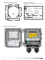
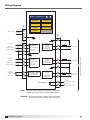
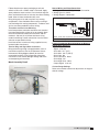
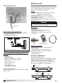
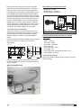
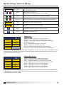
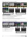
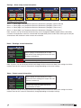
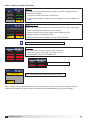
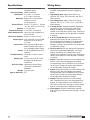
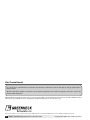
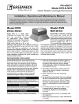
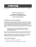
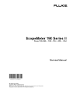
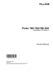
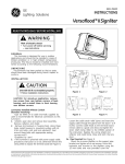
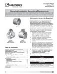
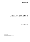
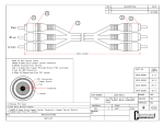
Document 479585 Fan Monitoring System ® User and Service Manual Please read and save these instructions for future reference. Read carefully before attempting to assemble, install, operate or maintain the product described. Protect yourself and others by observing all safety information. Failure to comply with instructions could result in personal injury and/or property damage! The fan monitoring system is designed to provide live access to key operating metrics as well as routine maintenance notifications. The fan monitoring system ultimately can assist in both reducing the operating cost of your system as well as helping avoid costly shut downs. Fan Monitoring System Features: • NEMA-4 and IP56 Enclosure Rating • Factory calibrated, plug and play wiring • 120-240 Vac or 24 Vac/Vdc input voltage • Two analog sensor inputs using any of the following: 4-20 mA 0-10 Vdc 2-10 Vdc • Available system monitoring Airstream Temperature Bearing Temperature Motor Current Motor Vibration Motor Speed Fan Vibration Motor Vibration Static Pressure Differential Pressure • One resistive temperature input (not used) • Three selectable isolated outputs matched to inputs 4-20 mA 0-10 Vdc 2-10 Vdc General Safety Information This instruction manual provides installation, operating, maintenance, and replacement parts information for the Fan Monitoring System. • LCD display with user-friendly touch panel interface • English or Metric readings • Simple Installation WARNING Improper installation, adjustment, alterations, service or maintenance can cause injury and property damage, as well as possible voiding of factory warranty. No person may install, operate, or maintain the fan monitor controller and transmitters without first being fully trained and qualified in the installation, operation and maintenance, and carefully reading and understanding the contents of this manual. If you have any questions about these instructions, contact your local representative. CAUTION Risk of electrical shock! More than one disconnect switch may be required to de-energize the equipment before servicing. ® Fan Monitoring System 1 Table of Contents General Fan Monitoring System Information Installation . . . . . . . . . . . . . . . . . . . . . . . . . . . . . . . . . . 2 Dimensions and Mounting Patterns . . . . . . . . . . . . . . 3 Label and Order Information. . . . . . . . . . . . . . . . . . . . 3 Wiring and System Components. . . . . . . . . . . . . . . . . 3 Wiring Diagram . . . . . . . . . . . . . . . . . . . . . . . . . . . . . . 4 Sensor Information Airstream Temperature Sensor Kit. . . . . . . . . . . . . . 5-6 Bearing Temperature Sensor Kit. . . . . . . . . . . . . . . 6-7 Bearing Vibration Sensor Kit. . . . . . . . . . . . . . . . . . 8-9 Current Sensor Kit. . . . . . . . . . . . . . . . . . . . . . . . . 9-10 Pressure Sensor Kit. . . . . . . . . . . . . . . . . . . . . . . 11-12 RPM Sensor Kit. . . . . . . . . . . . . . . . . . . . . . . . . . 12-13 Monitor Detail Display Setting Options and Setup. . . . . . . . . . . . . . 14 Settings: Sensor 1 and 2. . . . . . . . . . . . . . . . . . . . . 15 Settings: Temperature Resistive. . . . . . . . . . . . . . . . 15 Settings: System General. . . . . . . . . . . . . . . . . . . . . 16 Settings: Output 1, Output 2, Output 3. . . . . . . . . . 16 Settings: Alarm Relay Output. . . . . . . . . . . . . . . . . . 17 Home: Reading. . . . . . . . . . . . . . . . . . . . . . . . . . . . . 17 Home: Output. . . . . . . . . . . . . . . . . . . . . . . . . . . . . . 17 Home: History. . . . . . . . . . . . . . . . . . . . . . . . . . . . . 18 Home: Service . . . . . . . . . . . . . . . . . . . . . . . . . . . . . 19 Home: Default. . . . . . . . . . . . . . . . . . . . . . . . . . . . . 20 General Information Specifications. . . . . . . . . . . . . . . . . . . . . . . . . . . . . . . 21 Wiring Notes . . . . . . . . . . . . . . . . . . . . . . . . . . . . . . . 21 Maintenance. . . . . . . . . . . . . . . . . . . . . . . . . . . . . . . . 22 Replacement Parts. . . . . . . . . . . . . . . . . . . . . . . . . . . 22 Dimensions. . . . . . . . . . . . . . . . . . . . . . . . . . . . . . . . 23 Our Commitment. . . . . . . . . . . . . . . . . . . . . . . . . . . . . . 24 2 Fan Monitoring System Installation WARNING When wiring the instrument, you must follow industry standard practices for control and protection against electrostatic discharge (ESD). Failure to exercise good ESD practices may cause damage to the controller 1. Mount the monitor in the vertical plane using four #8‑32 screws. Open the front cover by unscrewing the two captive thumb screws to gain access to the four mounting locations pictured at right. Note: Mount the controller within 100 feet of the fan being monitored. 2. Disconnecting switch or breaker is required for the installation. It also must be suitably located and easily reached to remove power to the controller and must be marked as being the disconnecting means for the controller. 3. Remove terminal block TB1 and perform wiring for the pins listed below. For liquid tight applications, use only 1/2-inch liquid tight conduit. Terminal Block TB1: Input Power Pin 1 = Line (+) Pin 2 = Neutral (-) Pin 3 = Ground Note: All field wiring to be in ordinance with equivalent national standard. All wiring to be copper and 75°C rated minimum. 4. Wire TB2 accordingly. See wiring details for all sensor input(s), scaled output(s), and alarm signal. Note: Signal isolator may be required when two or more output signals share a common connection at the PLC/controller. 5. For resistive temperature sensor (by others): Only use Honeywell Industrial Temperature sensor part number 6655-90980004. Caution must be taken at install to not short sensor terminals or permanent damage may occur. 6. Provide power to the monitor to turn it on. 7. The monitor is factory programmed per sensor selections. Verify settings menu and adjust to meet installation requirements. (Refer to Display Setting Options and Setup section for details). When the above steps are completed, make sure the front cover is properly aligned to the housing and the two captive thumb screws are securely tightened. ® Label and Order Information Dimensions and Mounting Patterns Unit specific label is located on the inside cover of the controller. 4-5/32 in. (105.6 mm) CONFORMS TO UL STD 61010-2-030 WARNING! Maximum Sensor Loop Power: DO NOT EXCEED 24Vdc @ 100mA Per Sensor Input CERTIFIED TO CAN/CSA STDC22.2 #61010-2-030 E3192905 3-9/32 in. (83.3 mm) 5-3/8 in. (136.5 mm) Equipment For Measurement Fan Size: 24F17 Fan Model: VADS Sensor 1: Pressure Sensor 2: RPM Sensor 3: Resistive Description: Fan Monitoring System Input Power: 24Vac/dc, 10VA, 50/60Hz P/N: 5550123 Tag Mark: EF-1 Sales Order: 6606573 Agent Order #: K1543 P.O.# 597728 Date Code: 10/14 Schofield, WI 54476 U.S.A. 5 in. (127 mm) 2-10 Vdc Output Signal Tranmitter Calibration section 3/8 A 250 Vac MEDIUM LAG Line Neutral Wiring and System Components ® TB1 1 100 to 240 Vac 50/60 Hz 2 Input Power 3 Earth Ground TB2 1 4 to 20 mA/ 2-10 Vdc (+) 2 4 to 20 mA/ 2-10 Vdc (-) 3 Shield 4 Temperature 5 Sensor Fan Monitoring System 3 Wiring Diagram er Home 12:00 05/28/14 Settings Service 1) INPUT P Readings Defaults 2) SHIELD TB1 Outputs Assistance 1 History LINE INPUT POWER NO WA NEUTRAL 3) SENSO 2 TB2 3 4) OUTPU 10 TB2 4 to 20mA (+) 1 4 to 20mA (-) 0-10Vdc/2-10Vdc (+) SOURCE POWER TRANSMITTER 2 Sensor 1 Input 0-10Vdc/2-10Vdc (-) 3 Output 1 ISOLATED 4 to 20mA 0-10Vdc/2-10Vdc TRANSMITTER 0-10Vdc Input 2-10Vdc Input + - 11 - LOAD + Sensor 1 Output - 12 4 to 20mA (+) 5 SOURCE POWER TRANSMITTER 4 to 20mA (-) 0-10Vdc/2-10Vdc (+) 6 Sensor 2 Input 0-10Vdc/2-10Vdc (-) 7 0-10Vdc Input 2-10Vdc Input Output 2 + ISOLATED 4 to 20mA 0-10Vdc/2-10Vdc TRANSMITTER - 13 - LOAD + Sensor 2 Output - 14 15 8 Resistive Temperature Sensor (NOT USED) 9 + - Resistive 1 Input SOURCE POWER FOR TEMP SENSOR Resistive Output + ISOLATED 4 to 20mA 0-10Vdc/2-10Vdc TRANSMITTER - Alarm Output 16 17 - LOAD + Sensor 3 Output (NOT USED) - 18 Alarm (+) (Open Collector Output) 19 Alarm (+) (Open Collector Output) To BMS (Building Managment System) 4 5) ALARM 6) RESIST INPUT NOTE: UNIT IS NOT WATER TIGHT UNTIL AFTER UNIT AND CONDUIT 7) Resistiv TRAN CONNECTION ARE SEALED BY CUSTOMER AFTER WIRING. WARNING: BEFORE APPLING INPUT POWER, CHECK FOR PROPER INPUT VOLTAGE. REFER TO DOOR LABEL FOR DETAILS. 4 Fan Monitoring System ® Airstream Temperature Sensor Kit Sensor used to detect system process temperature. Temperature sensor kit is provided with one temperature probe and transmitter. Fan monitor can provide a system fault alarm for high or low temperature and current status reading. Ratings: Enclosure: NEMA-4X (IP 66) with supplied mounting enclosure Temperature Range: Temperature Probe: -148° to 212°F (-100° to 100°C) Transmitter: -4° to 158°F (-20° to 70°C) Input Voltage: 24 Vdc Output Signal: 4-20 mA Accuracy: ±0.9°F (±0.5°C) WARNING Turn fan off and lock out power prior to mounting any sensors or running connection wiring. Kit includes: J type thermocouple probe with wiring, 4 ft. (1.2 m) length Temperature transmitter Transmitter enclosure Transmitter and Enclosure Mounting: The mounting location of the temperature transmitter enclosure should be near the probe mounting location. Note that the maximum distance between transmitter and fan monitor is 100 feet (30 m). Mount temperature transmitter enclosure using conduit and fittings. Lower connection stem has offset collar to accept conduit clamp. Install temperature transmitter in enclosure using supplied screws, located inside of enclosure. Temperature Probe and Signal Wire Connection: Bring temperature probe wiring in through bottom stem of transmitter enclosure. See Temperature Sensor Interconnect Wiring Diagram (below) for terminal connection locations. Final connection wiring from transmitter to fan monitor is brought through side stem center opening of the temperature transmitter. Mock Assembly Detail Transmitter Enclosure Conduit and Wire (by others) Clamp (by others) Mounting Bracket Thermocouple Probe with Wiring Temperature Transmitter Probe in Air Sensor Thermocouple Sensor Interconnect Wir Electronic Monitor - Thermocouple Probe and Transmitter Installation ® + 4-20 MA INPUT SIGNAL + OUT SHIELD 1 5 2 6 4 4 1 OR 2 NOTE: Shield cable required from sensor to electronic monitor. NO Temperature Sensor Interconnect Wiring Electronic Monitor TB2 BEARING LOCATION Thermocouple Probe Mounting: At location to have temperature measured, secure provided mounting bracket to ductwork or other fixture. Attach mounting bracket in desired orientation. If needed, drill 5/16 inch (6.3 mm) diameter hole at location where the temperature probes would pass through ductwork. Secure probe to mounting bracket. Note the thermocouple section of probe should not touch bracket as this will give false temperature reading. TC TRANSMITTER TEMPERATURE SENSOR Sensor 2 Input RED AIR TEMPERATURE Sensor 1 Input TB2 WHITE 4-20 MA INPUT SIGNAL VIBRATION SENSOR TRANSMITTER WHITE BLACK Sensor 2 Input Hardware not included: Signal wiring between transmitter enclosure and fan monitor Mounting fasteners for transmitter housing Mounting fasteners for temperature probe bracket Sensor 1 Input 1/2-inch FNPT Transmitter Enclosure Sensor Wiring and Point Connection: Wiring size: 18/22 AWG (by others) to fan monitoring system Wiring Type: 2w shield Wiring diagram / connection: 1 5 4 4 Fan Monitoring System 2 6 SHIELD 5 Factory Fan Monitor Default Settings for Airstream Temperature Sensor(s): Type: Temperature Signal: 4-20 mA Scale Min: -148°F (-100°C) Scale Max: 212°F (100°C) Alarm Low: No Alarm Low Value: None Alarm High: No Alarm High Value: None Output Signal: 4-20 mA Custom Range Settings: Refer to fan monitor section for adjustments in range or default settings. Bearing Temperature Sensor Kit Sensor used to detect bearing temperatures. Each bearing temperature sensor kit is provided with one thermocouple terminal ring and temperature transmitter. Fan monitor provides a system fault alarm for high temperature and analog outputs for current status reading. Ratings: Enclosure: NEMA-4X (IP 66) with supplied mounting enclosure Temperature Range: Temperature Terminal Ring: 32° to 482°F (0 to 250°C) Transmitter: -4° to 158°F (-20 to 70°C) Input Voltage: 24 Vdc Output Signal: 4-20 mA Accuracy: ±0.9°F (±0.5°C) WARNING Turn fan off and lock out power prior to mounting any sensors or running connection wiring. Kit includes: J type thermocouple terminal ring with wiring 4 ft. (1.2 m) length Packet of epoxy adhesive Temperature transmitter Transmitter enclosure Thermocouple Probe with Wiring Temperature Transmitter Epoxy Adhesive 1/2-inch FNPT Transmitter Enclosure Hardware not included: Signal wiring between transmitter enclosure and fan monitoring system Mounting fasteners for transmitter housing Tie downs and zip ties Temperature Ring and Transmitter Installation Terminal Ring Mounting: The thermocouple terminal ring is mounted on the bearing housing. For best results, install terminal ring near the bearing grease zerk or bearing insert. Do not install on bearing feet or directly on the insert. Prepare surface where sensor will mount by removing any dust or oils with a dry cloth or with alcohol wipe. 6 Fan Monitoring System ® Sensor Interconnect Wiring to the Fan Monitor Sensor Wiring and Point Connection: Wiring size: 18/22 AWG (by others) to fan monitor Wiring Type: 2w shield Wiring diagram / connection: Transmitter and Enclosure Mounting: 1 5 + 2 6 Install temperature transmitterOUTenclosure near terminal ring mounting location, either on fan or remotely. Note 4 4 the maximum distance between transmitter and fan 1 OR 2 monitor is 100 feet (30 m). Mount enclosure using NOTE: Shield cable required from sensor to electronic monitor. conduit and fittings. Lower connection stem has offset Temperature Sensor Interconnect Wiring collar to accept conduit clamp. 4-20 MA INPUT SIGNAL - TC + TRANSMITTER TEMPERATURE SENSOR - 4-20 MA INPUT SIGNAL WHITE BLACK SHIELD 1 OR 2 Mock Detailfrom sensor to electronic monitor. NOTE:Assembly Shield cable required Clamp (by others) JUMPER LOCATION + - REV 5V BID. NOTE: Shield cable required from sensor to electronic monitor. Bearing Sensor Interconnect Wiring O 4-20 MA INPUT SIGNAL SHIELD 1 5 2 6 3 7 Epoxy 4 4 Fastened JUMPER LOCATION 0-10 VDC INPUT SIGNAL HIGH VOLTAGE POWER LEAD TO MOTOR CURRENT TRANSMITTER SHIELD Custom Range Settings: Refer to fan monitor section for adjustments in range or Electronic default settings. Monitor TB2 1 2 3 4 5 6 RPM SENSOR 4 to 20mA TRANSMITTER 7 Proximity Sensor SENSOR TYPE: PNP BROWN 10 8 11 4-20 MA INPUT SIGNAL 9 12 BLACK SHIELD BLUE ® Sensor Interconnect Bearing Wiring 1 5 2 6 3 7 4 4 1 OR 2 1 OR 2 NOTE: Shield cable required from sensor to electronic monitor. Sensor Pressure Thermocouple Sensor 1 Input 0-50A 0-10A 0-20A Factory Fan Monitor Default Settings for Bearing Temperature Sensor(s): Electronic Monitor TB2 Type: Temperature Signal: 4-20 mA Scale Min: 32°F (0°C) Scale Max: 482°F (250°C) + 2 6 Alarm Low: No 3 7 Alarm Low Value: None 4 4 Alarm High: No 1 OR 2 Alarm High Value: None NOTE: cable4-20 required OutputShield Signal: mAfrom sensor to electronic monitor. TB2 Sensor 2 Input AC DC DIR 10V UNIT UNIT UNI. RNG RNG SWITCH LOCATION INPUT POWER LOW PRESSURE TUBE Conduit and Wire Electronic Monitor (by others) Sensor 1 Input HIGH PRESSURE TUBE - 4 Sensor 2 Input Transmitter Enclosure + 4 1 OR 2 Current Sensor Interconnect Wiring Vibration Sensor Interconnect Wiring TRANSMITTER PRESSURE SENSOR 6 SHIELD DRIVE SHAFT KEYWAY BEARING LOCATION 4-20 MA INPUT SIGNAL Sensor 2 Input Sensor 1 Input Electronic Monitor Terminal Ring and Signal Wire Connection: TB2 Bring terminal ring wiring in through bottom stem of transmitter enclosure. See the Temperature Sensor Interconnect Wiring diagram (below) for terminal VIBRATION Final connection wiring from connection locations. 1 5 SENSOR 2 6 side stem transmitter to TRANSMITTER fan monitor brought through 4 4 center opening of transmitter. 5 2 OUT SHIELD Install transmitter in enclosure using supplied screws, located inside of enclosure. 1 + Sensor 1 Input TRANSMITTER TEMPERATURE SENSOR RED BEARING TEMPERATURE Sensor 2 Input RED AIR TEMPERATURE TB2 WHITE Sensor 1 Input WHITE Electronic Monitor Sensor 2 Input Sensor 1 Input Electronic Monitor Bring wiring out of fan and away from any moving TB2 components. Care should be taken to ensure wiring is not interfering with moving components. Tie downs and TC zip ties are recommended to -secure wiring. + Sensor 2 Input Follow directions on epoxy packaging to activate adhesive. Mix until a uniform color is achieved. Apply epoxy adhesive to one surface. Press terminal ring into place and hold for five to ten minutes to achieve holding bond. Allow 24 hours for bond to fully cure. NOTE: Shield cable required from sensor to electronic monitor. RPM Interconnect Wiring Fan Monitoring System 7 Vibration Sensor Kit Sensor used to detect vibration on fan shaft bearing or motor bearing. Fault setting for alarm or trend indicating future failure. Fan monitoring system is available with one or two bearing vibration sensors. Single vibration sensor kit systems can monitor a single vibration point either on a fan shaft bearing or the motor depending which is more critical. Two vibration sensor kit systems can monitor both fan shaft bearings or one shaft bearing and motor. Fan Shaft Bearing Monitoring: Align the sensor to the shaft as shown in Figure 1. Vibration sensor positioned to detect vibration in the horizontal direction. Orient sensor with wiring pin connection in the direction cable will run. Position sensor and wiring not to interfere with moving components (belts, shafting, sheaves). Mark sensor mounting location prior to applying epoxy adhesive. REVISION Figure 1 Top View Ratings: Enclosure: NEMA-4 (IP 67) Temperature Range: -40° to 185°F (-40° to 85°C) Input Voltage: 10 Vdc minimum, 30 Vdc maximum Output Signal: 4-20 mA Accuracy: 5% transverse sensitivity, ±2% repeatability Bearing Bearing Shaft WARNING Sheave Turn fan off and lock out power prior to mounting any sensors or running connection wiring. Sensor 2 Sensor 1 One sensor per kit is provided. PAINT PART NO. MAT'L GAUGE DESCRIPTION DRAWN BY Kit includes: One vibration sensor Sensor mounting base Packet of epoxy adhesive Connection cable Vibration Sensor SYM ---- ---- Motor Monitoring ---Vibration sensor can be positioned to detect vibration in either the horizontal or axial direction. Align the Motor sensor to the shaft as shown in Figure 2. Sensor can be mounted on motor or on motor mounting pedestal. Orient with wiring pin connection in the direction cable will run. Position sensor and wiring not to interfere with moving components Sensor (belts, shafting, sheaves). Mark sensor mounting location prior to applying epoxy adhesive. Motor DATE ECO ---- SUPERSEDES TITLE SCALE ---1/1 CAD DRAWING NO. Motor Sensor Sensor Sensor Sensor mounted on motor Motor Motor Motor Connection Cable Hardware not included: Tie downs and zip ties Sensor Sensor Sensor Sensor mounted on motor mounting pedestal Vibration Sensor Assembly Motor Positioning: Vibration sensor detects vibration in a single plane parallel to sensor base. The orientation of the vibration sensor determines which axis is measured. Motor Vibration Sensor Mounting: Sensor Sensor will mount by removing Prepare surface where sensor any dust or oils with a dry cloth or with alcohol wipe. Follow directions on epoxy packaging to activate adhesive. Apply epoxy adhesive to one surface. Press sensor into place and hold for five to ten minutes to achieve holding bond. Allow 24 hours for bond to fully cure. If single vibration sensor is being connected or if two vibration sensors are used with second vibration sensor for motor vibration detection, place first sensor between the fan shaft bearings, but closer to the drive bearing, nearer to the fan drive sheaves or motor. Connect wiring cable and run out of fan and away from any moving components. Care should be taken to ensure wiring is not interfering with moving components. Tie downs and zip ties are recommended to secure wiring. Bolt sensor into threaded hole in mounting base, use breakable thread lock if necessary for a stronger connection. 8 Fan Monitoring System ---------------- Figure 2 Sensor Mounting Base Motor Epoxy Adhesive ---- ENG. REF. ---- ® B Current Sensor Kit Mock Assembly Detail Bearing Sensor used to detect current (amps) usage of motor. Fan monitor provides fault setting for alarm, run time value for maintenance and power usage. Cable Sensor Interconnect Wiring to the Fan Monitor + TRANSMITTER TEMPERATURE SENSOR - 4-20 MA INPUT SIGNAL 1 5 2 6 + OUT 4 SHIELD 4 1 OR 2 Sensor Wiring and Point Connection: NOTE: Shield cable required from sensor to electronic monitor. Wiring size: 18 AWG Temperature Sensor Interconnect Wiring Wiring Type: 2w shield Wiring diagram / connection: WHITE RED BEARING TEMPERATURE TRANSMITTER TEMPERATURE SENSOR 4-20 MA INPUT SIGNAL Sensor 2 Input - TC Sensor 2 Input RED AIR TEMPERATURE Sensor 1 Input TB2 WHITE Sensor 1 Input Electronic Monitor Sensor Ratings: Enclosure: NEMA-4/4X, (IP 66/67) with supplied mounting enclosure Temperature Range: 5° to 104°F (-15° to 40°C) Input Voltage: NA Output Signal: 0 to 10 Vdc Electronic Monitor Maximum Motor Current: 0 to 50 amps or TB2 0 to 100 amps Maximum Distance from Fan Monitor: 100 feet (30 m) TC + Accuracy: ±1%, 2 to 100%- FSO 1 5 2 6 WARNING - + OUT Turn fan off and lock out power prior to mounting any 4 4 sensors or running connection wiring. SHIELD 1 OR 2 NOTE: Shield cable required from sensor to electronic monitor. Kit includes: Current sensor Bearing Sensor Interconnect Wiring Polycarbonate mounting enclosure Electronic Monitor Electronic Monitor WHITE BLACK SHIELD 6 4 4 JUMPER LOCATION 0-10 VDC INPUT SIGNAL HIGH VOLTAGE POWER LEAD TO MOTOR CURRENT TRANSMITTER + 2 6 - 3 7 4 4 SHIELD 1 OR 2 Current Sensor Inside Enclosure 1 OR 2 Sensor 2 Input 5 2 0-50A 1 0-10A 0-20A Sensor 2 Input VIBRATION SENSOR TRANSMITTER Sensor 1 Input BEARING LOCATION 4-20 MA INPUT SIGNAL Sensor 1 Input TB2 TB2 Polycarbonate Mounting Enclosure NOTE: Shield cable required from sensor to electronic monitor. NOTE: Shield cable required from sensor to electronic monitor. Vibration Sensor Interconnect Wiring Current Sensor Interconnect Wiring Hardware not included: Mounting fasteners for enclosure Signal wire between sensor and fan monitoring Electronic Monitor system O 4-20 MA INPUT SIGNAL SHIELD 1 5 2 6 3 7 4 4 Pressure Sensor Interconnect Wiring Custom Range Settings: Refer to fan monitor section for adjustments in range or default settings. 1 3 2 Current Sensor Installation 4 5 6 Sensor 2 Input BID. TB2 LOW PRESSURE TUBE DRIVE SHAFT KEYWAY AC DC REV 5V SWITCH LOCATION INPUT POWER JUMPER LOCATION DIR 10V UNIT UNIT UNI. RNG RNG Sensor 2 Input TRANSMITTER PRESSURE SENSOR Sensor 1 Input HIGH PRESSURE TUBE Sensor 1 Input Factory Fan Monitor Default Settings for Vibration Sensor(s): + Electronic Monitor Type: Vibration TB2 Signal: 4-20 mA Scale Min: 0 IPS (inches per second) [0 mm/sec] - [42.2 mm/sec] Scale Max: 1.66+ IPS Alarm Low: No Alarm Low Value: None Alarm High: Yes Alarm High Value: 0.65 IPS [16.5 mm/sec]1 OR 2 NOTE: Shield cable4-20 required Output Signal: mAfrom sensor to electronic monitor. 0 to 50 AMPS Enclosure Mounting: 1 5 or Current sensor enclosure can on the fan 7 8be installed 9 2 6 Proximity Sensor remotely. Do not exceed maximum distance between 12 10 11 3 7 current sensor and fan monitor. Final wiring to primary 4 4 system transmitter is the responsibility of others. 1 OR 2 RPM SENSOR 4 to 20mA TRANSMITTER SENSOR TYPE: PNP 4-20 MA INPUT SIGNAL BROWN BLACK SHIELD BLUE Install torequired desired mounting using the NOTE:enclosure Shield cable from sensor to location electronic monitor. four (4) through holes in the back of the enclosure. See RPM Interconnect Wiring Figure 3 or Figure 4 on next page. Figure 3: 0 to 50 amps 2.50 in. (63.5 mm) 3.15 in. (80.0 mm) 4.47 in. (113.54 mm) 5.12 in. (130.05 mm) ® 1.97 in. (50.04 mm) 4.82 in. (122.43 mm) Fan Monitoring System 9 Mock Assembly Detail #2 Figure 4: 0 to 100 amps Current Sensor Inside Enclosure 4.80 in. (121.92 mm) 5.51 in. (139.95 mm) 4.12 in. (104.65 mm) 8.35 in. (212.09 mm) Conduit and Wiring (by others) 4.91 in. (124.71 mm) 9.08 in. (230.63 mm) Sensor Interconnect Wiring to the Fan Monitorin Temperature Sensor Interconnect Wiring NOTE - Sensor 2 Input 1 5 SHIELD 2 6 4 4 4-20 MA INPUT SIGNAL 1 5 2 6 4 4 + OUT SHIELD Electronic Monitor TB2 0-10A 0-20A Sensor 1 Input BEARING LOCATION WHITE BLACK SENSOR TRANSMITTER + 1 OR 2 •Wiring size: 18/22 AWG (by others) to fan monitoring NOTE: Shield cable required from sensor to electronic monitor. controller • Wiring Type: 2w shield Bearing Sensor Interconnect Wiring • Wiring diagram / connection: JUMPER LOCATION 0-10 VDC INPUT SIGNAL HIGH VOLTAGE • Only one leadVIBRATION thru sensor, single and three phase 4-20 MA INPUT SIGNAL TC Sensor Wiring and Point Connection: All local electrical codes and proper wiring techniques are to be followed during installation. Liquid tight Electronic Monitor conduit is required to maintain enclosure TB2 rating. Mock Assembly Detail #1 - TRANSMITTER TEMPERATURE SENSOR Sensor 2 Input SHIELD RED BEARING TEMPERATURE Sensor 1 Input 4-20 MA INPUT SIGNAL TB2 WHITE POWER LEAD TO MOTOR CURRENT TRANSMITTER Sensor 2 Input TRANSMITTER TEMPERATURE SENSOR Electronic Monitor Sensor 1 Input RED AIR TEMPERATURE Control Wiring 0-50A WHITE Power Wiring Sensor 2 Input Sensor 1 Input Current Sensor Connection: • Remove current sensor from enclosure •Remove required knock-outs on enclosure for installation. Main power wiring is run through the sides and control wiring can be run through the bottom. Monitor •Install any connector fitting into knock-outElectronic locations TB2 as necessary • Feed control wiring in through enclosure housing TC + •Connect control wiring to current sensor, see Mock Assembly Detail Image #1 and the Current Sensor 1 5 + Interconnect Wiring Diagram. 2 6 OUT • Mount current sensor back into enclosure 4 4 •Run main power wiring in through corresponding 1 OR 2 knock-out holes. See Mock Assembly Detail #1 and NOTE: Shield cable required from sensor to electronic monitor. #2 for wire placement. + 2 6 - 3 7 4 4 SHIELD 1 OR 2 1 OR 2 NOTE: Shield cable required from sensor to electronic monitor. NOTE: Shield cable required from sensor to electronic monitor. Vibration Sensor Interconnect Wiring Current Sensor Interconnect Wiring - BID. LOW PRESSURE TUBE O 4-20 MA INPUT SIGNAL 1 5 2 6 3 7 4 4 4 to 20mA TRANSMITTER SENSOR TYPE: PNP 4-20 MA INPUT SIGNAL Sensor 2 Input AC DC JUMPER LOCATION REV 5V SWITCH LOCATION Control Wiring + DIR 10V UNIT UNIT UNI. RNG RNG Factory Fan Monitor Default Settings for Current Electronic Monitor Sensor: TB2 3 1 2 Type: Current 4 Signal: 0 to 10 Vdc 5 6 RPM SENSOR Scale Min: 0 amps Scale Max: 50 or 100 amps 1 5 7 8 9 2 6 Alarm Low: No Proximity Sensor 3 7 Alarm Low Value: None 10 11 12 4 4 Alarm High: Yes 1 OR 2 Alarm High Value: Fan mark specific, factory set at NOTE: Shield cable required sensor to electronic monitor. motorfrom nameplate FLA x 1.15 Wiring Output Signal:RPM 0 to Interconnect 10 Vdc Sensor 1 Input TRANSMITTER PRESSURE SENSOR INPUT POWER NOTE: One power Electronic lead thruMonitor sensor TB2 shown DRIVE SHAFT KEYWAY - Sensor 2 Input HIGH PRESSURE TUBE + Sensor 1 Input Resolution Jumper Set 0 to 50A BROWN BLACK SHIELD 1 OR 2 NOTE: Shield cable required from sensor to electronic monitor. Pressure Sensor Interconnect Wiring SHIELD BLUE Custom Range Settings: Refer to fan monitor section for adjustments in range or default settings. 10 Fan Monitoring System ® Place the bracket flush with the end of the tube and crimp into place Pressure Sensor Kit 6 mm hollow tube Pressure sensor used to detect system pressure or pressure differential. Each pressure sensor kit is provided with two pressure probes and a pressure transmitter. For static pressure reading relative to atmosphere a single pressure probe is necessary. For pressure differential measurements two pressure probes are required. Fan monitor can provide a system fault for alarm or current status reading. 1.00 in. (25.4 mm) .75 in. (19.5 mm) Flange bracket Transmitter Mounting: 1.00a in. location near pressure Install pressure transmitter (25.4 in mm) probe(s) mounting location(s). Note maximum in. distance between 2.00 pressure transmitter and primary (50.8 mm) system transmitter is 100 feet (30 m). Mount pressure transmitter with pressure ports and electrical connection downwards. 1/4 in. hose barb Figure 5 Ratings: 2.64 in. Enclosure: N EMA-4X (IP 66) with supplied mounting (67.06 mm) enclosure Temperature Range: 0° to 150°F (-18° to 66°C) Input Voltage: 10 to 35 Vdc Output Signal: 0 to 10 Vdc Negative Accuracy: ±1% 2.64 in. (67.06 mm) Positive Pressure Port (+) Pressure Port (-) 2.17 in. (55.12 mm) Turn fan off and lock out power prior to mounting any sensors or running connection wiring. Kit includes: Two (2) pressure probes with integral mounting bracket and gasketing Pressure transmitter Pressure Transmitter Hardware not included: 3/16 inch (4.8 mm) inner diameter tubing required for connection between probe(s) and transmitter Mounting fasteners for transmitter housing Mounting fasteners for pressure probe(s) Pressure Probe Mounting: Drill 5/16 inch (6.3 mm) diameter hole at location where pressure measurement is desired. Insert pressure probe into hole. Secure probe using pre-punches holes until bracket is flush with mounting location and gasket is compressed. Place the bracket flush with the end of the tube and crimp into place 6 mm hollow tube Negative Pressure Port (-) 2.64 in. (67.06 mm) Pressure Probe Connection: Connect pressure probe(s) to transmitter using round tubing. Actual tubing length required varies based on distance between probes to transmitter mounting location. Static pressure - single probe Negative static pressure measurement. Connect the pressure probe to the negative (-) port, as indicated on the transmitter. Leave positive (+) port open to atmosphere. Positive static pressure measurement. Connect the pressure probe to the positive (+) port, as indicated on the transmitter. Leave negative (-) port open to atmosphere. Figure 6 Pressure Probe and Transmitter Installation Figure 4 Positive Pressure Port (+) (Three) .188 in. (47.75 mm) holes equally spaced on a 4.115 B.C. WARNING Pressure Probes 2.56 in. (65.02 mm) Flange bracket Negative Pressure Port (-) Positive Pressure Port (+) Differential pressure – two probes Connect each probe to the corresponding port on the transmitter. If measured results are opposite, then switch tubing into opposite port. 1.00 in. (25.4 mm) .75 in. (19.5 mm) 1/4 in. hose barb 1.00 in. (25.4 mm) Mounting bracket detail for the pressure probe. 2.00 in. (50.8 mm) 1.00 in. (25.4 mm) .75 in. (19.5 mm) bracket 4 in. hose barb 1.00 in. (25.4 mm) 2.00 in. (50.8 mm) ® 2.64 in. (67.06 mm) 2.56 in. (65.02 mm) Fan Monitoring System Negative 11 Electronic Monitor 1 5 2 6 4 4 + OUT SHIELD TRANSMITTER TEMPERATURE SENSOR - Temperature Sensor Interconnect Wiring Pressure Tubing (by others) SHIELD 1 5 2 6 4 4 0-10A 0-20A Sensor 2 Input WHITE BLACK Sensor 1 Input BEARING LOCATION TB2 VIBRATION SENSOR TRANSMITTER JUMPER LOCATION POWER LEAD TO MOTOR SHIELD TB2 O 4-20 MA INPUT SIGNAL 1 5 2 6 3 7 4 4 DRIVE SHAFT KEYWAY - BID. LOW PRESSURE TUBE Sensor 2 Input AC DC + REV 5V SWITCH LOCATION JUMPER LOCATION DIR 10V UNIT UNIT UNI. RNG RNG Electronic Monitor TB2 Electronic Monitor Sensor 1 Input TRANSMITTER PRESSURE SENSOR INPUT POWER + 2 6 Kit includes: 3 7 Proximity sensor Stainless steel sensor mounting bracket 4 4 1 OR 2 Polycarbonate enclosure NOTE: WiringShield between sensor from and sensor rpm transmitter cable required to electronic monitor. Transmitter Current Sensor Interconnect Wiring CURRENT TRANSMITTER NOTE: Shield cable required from sensor to electronic monitor. •W iring size: 18/22 AWG (by others) to fan monitor Vibration Sensor Interconnect Wiring • Wiring Type: 2w shield • Wiring diagram / connection: HIGH PRESSURE TUBE 0-10 VDC INPUT SIGNAL HIGH VOLTAGE Sensor Wiring and Point Connection: - TB2 Turn fan off and lock out power prior to mounting any sensors or running connection wiring. 1 OR 2 + Electronic Monitor WARNING Electronic Monitor 4-20 MA INPUT SIGNAL 5 SHIELD NOTE: Shield cable required from sensor to electronic monitor. Conduit and Wire (by others) 1 2 6 OUT Ratings: Enclosure: NEMA-4X, (IP 67) proximity sensor and 4 4 supplied transmitter enclosure 1 OR 2 Temperature Range: 32° to 120°F (0° to 50°C) NOTE: Shield cable required from sensor to electronic monitor. Input Voltage: 9 VCD minimum, 32 Vdc maximum Bearing Sensor Output Signal: 4-20 mA Interconnect Wiring Maximum Distance from fan monitor: 100 feet (30 m) Accuracy: ±0.1% 1 OR 2 Probe 4-20 MA INPUT SIGNAL + 1 2 3 4 5 6 RPM SENSOR 4 to 20mA TRANSMITTER Proximity Sensor Proximity Sensor Polycarbonate Enclosure 7 8 9 with Mounted Transmitter SENSOR TYPE: PNP BROWN 10 11 4-20 MA INPUT SIGNAL Wiring1 12 Sensor 2 Input - 4-20 MA INPUT SIGNAL Sensor 2 Input TRANSMITTER TEMPERATURE SENSOR RED Sensor 1 Input + Sensor 1 Input TC Sensor 2 Input - WHITE BEARING TEMPERATURE Sensor 1 Input Pressure Transmitter Sensor 2 Input RED Sensor 1 Input WHITE Electronic Monitor TB2 Sensor used to detect rpm of fan. Fan monitor provides fault setting for alarm exceeding maximum limit, actual TC run time, and maintenance for bearing lubrication, + - fan motor lubrication and belt replacement. TB2 AIR TEMPERATURE RPM Sensor Kit 0-50A Mock Assembly Detail 5 2 6 3 7 Hardware not included: 4 4 Signal wiring from enclosure to fan monitor 1 OR 2 Sensor target Shield cable required from sensor to electronic monitor. NOTE: Mounting fasteners for mounting bracket RPM Interconnect Wiring Mounting fasteners for transmitter enclosure Tie downs and zip ties Adapter bracket BLACK SHIELD SHIELD BLUE 1 OR 2 NOTE: Shield cable required from sensor to electronic monitor. Pressure Sensor Interconnect Wiring Factory Fan Monitor Default Settings for Pressure Sensor(s): Type: Pressure Signal: 0 to 10 Vdc Scale Min: -28 inches w.g. (-6.9 KPa) Scale Max: 28 inches w.g. (6.9 KPa) Alarm Low: No Alarm Low Value: None Alarm High: No Alarm High Value: None Output Signal: 0 to 10 Vdc Proximity Sensor Mounting: Determine location of sensor mounting bracket. Sensor needs to be mounted near fan shaft to detect rotation. Maximum distance between sensor and target is .60 inch (15.2 mm). Mounting bracket adjustment may be necessary depending on fan configuration. Sensor Bearing Custom Range Settings: Sensor Target Refer to fan monitor section for adjustments in range or C-bracket by others This drawing has been default settings. removed from the Washers Installation Instruction Sensor Installation of RPM Sensor Bearing Keyway may be necessary to balance coupling by others Sensor Target by others Bearing Sensor Bearing Keyway 12 Fan Monitoring System ® 4 4 CURRENT TRANSMITTER TRANSMITTER PRESSURE SENSOR BID. O 4-20 MA INPUT SIGNAL SHIELD 1 5 2 6 3 7 4 4 Install enclosure to desired mounting location using the four (4) thru-holes in the back of the enclosure. See Figure 8. Figure 8 2.50 in. (63.5 mm) 3.15 in. (80.0 mm) 1.97 in. (50.04 mm) 4.82 in. (122.43 mm) 5.12 in. (130.05 mm) 7 4 4 1 OR 2 Wiring size: 18 AWG Current Sensor Interconnect Wiring Wiring Type: 3w shielded Wiring diagram / connection: Electronic Monitor TB2 1 2 4 5 3 50 to 100 AMPS 6 RPM SENSOR 4 to 20mA TRANSMITTER 7 Proximity Sensor SENSOR TYPE: PNP BROWN 10 8 11 4-20 MA INPUT SIGNAL 9 12 BLACK SHIELD 1 OR 2 Transmitter Enclosure Mounting: NOTE: Shield cable required sensor to electronic monitor. Transmitter enclosure can from be installed on the fan or Pressure Sensor Interconnect Wiring of 100 ft. remotely. Do not exceed maximum distance (30 m) between transmitter and electronic monitor. Wiring to electronic monitor is the responsibility of others. 4.47 in. (113.54 mm) 6 3 NOTE: Shield cable required from sensor to electronic monitor. DRIVE SHAFT KEYWAY REV 5V Sensor 2 Input AC DC JUMPER LOCATION DIR 10V UNIT UNIT UNI. RNG RNG SWITCH LOCATION 0 to 50 AMPS INPUT POWER 2 - Sensor Wiring and Point Connection: LOW PRESSURE TUBE Sensor 1 Input HIGH PRESSURE TUBE + SHIELD 1 OR 2 Remove one adjustment nut from sensor and slide proximity sensor into mounting bracket. Thread nut NOTE: Shield cable required from sensor to electronic monitor. back on sensor to secure the sensor to the bracket. Vibration Sensor Interconnect Wiring Final adjustments to proximity sensor location can be made through loosening and tightening of threaded nuts. Attach wiring to end of sensor. Locate mounting + Electronic Monitor position of bracket and mark location. Remove sensor TB2 and wring from bracket and secure bracket to fan at location marked. Bracket can be secured using selftaping screws or using + - an epoxy adhesive. Reinstall sensor and wiring in mounting bracket. Secure sensor wiring avoiding any rotating components. Tie downs and zip ties are recommended to secure wiring. Sens 6 Sens 5 2 Connect proximity sensor wiring cable to transmitter. Make final connection between transmitter enclosure and fan monitor. BLUE Sensor 2 Input SHIELD 1 0-10 VDC INPUT SIGNAL HIGH VOLTAGE POWER LEAD TO MOTOR Sensor 1 Input WHITE BLACK Sensor VIBRATION SENSOR TRANSMITTER Sensor BEARING LOCATION 4-20 MA INPUT SIGNAL 1 5 2 6 3 7 4 4 1 OR 2 NOTE: Shield cable required from sensor to electronic monitor. RPM Interconnect Wiring Factory Fan Monitor Default Settings for RPM Sensor(s): Type: RPM Signal: 4-20 mA Scale Min: 0 RPM Scale Max: 4200 RPM Alarm Low: No Alarm Low Value: None Alarm High: Yes 4.80 in. (121.92 mm) Alarm High Value: Nameplate fan RPM x 1.02 5.51 in. (139.95 mm) Output Signal: 4-20 mA Custom Range Settings: 8.35 in. (212.09 mm) 9.08 in.adjustments (230.63 mm) Refer to fan monitor section for in range or default settings. Mock Assembly Detail RPM Transmitter Enclosure Conduit and Wire (by others) Mounting Bracket Sensor Cable ® Fan Monitoring System 13 4.12 in. (104.65 mm) 4.91 in. (124.71 mm) Monitor Settings, Options and Setup Navigation Input Yellow – Menu; Grey – Name; Green – Reading/Entry, status ok; Red – Reading, Alarm value Alarm White Alarm icon system ok; Red Alarm icon flashing or solid color system in alarm Select Green – Control item selected; Red – Alarm item selected Not Select Back Next Back Move back one screen to previous page Next Move forward one screen to the next page Home Quick button to go directly back to the home screen Help Home Green – Control item is not selected; Red – Alarm item is not selected 12:00 05/28/14 Settings Service Readings Defaults Outputs Assistance History Quick button to the help screen Home Screen Settings: System settings menu screen(s) selection. Readings: Sensor inputs real-time readings from system. Outputs: System output analog real-time readings to building management system. History: System history for sensors and alarms. Service: Maintenance functions and set up. Defaults: Reset to factory defaults or save user defaults. Assistance: General assistance to Greenheck Fan Corporation. The screen is a LCD touch screen. Pressing any of the yellow bars will take you into the menu for that portion of the monitoring system. Touching the alarm icon will show you the alarm history and the question mark will take you to the help information for that screen. Settings Main Screen Settings Sensor 1 Output 1 Sensor 2 Output 2 Temp Output 3 System Alarm Sensor 1: Settings screen(s) access for Sensor #1 Sensor 2: Settings screen(s) access for Sensor #2 Temp: Setting screen(s) access for Resistive Temperature System: Setting screen(s) access for general system settings Output 1: Settings screen(s) access for Output #1 Output 2: Settings screen(s) access for Output #2 Output 3: Settings screen(s) access for Output #3 Alarm: Settings screen(s) access for system Alarm The screen is a LCD touch screen. Pressing any of the yellow bars will take you into the menu for that portion of the monitoring system. Touching the home icon take you back to the home screen and the question mark will take you to the help information for that screen. 14 Fan Monitoring System ® Settings – Sensor 1 and Sensor 2 setup screen information: Sensor 1 - 1 Sensor 1 - 2 Sensor 1 - 3 Sensor 1 - 4 SCALE Vibration Temp 4 - 20 MA Current RPM 0 - 10 VDC Minimum (______) Custom 2 - 10 VDC Maximum (______) Pres Back Next Back Next Back Next Alarm Low (______) Alarm High (______) Back Back to Settings Sensor 1 - Custom Name (______) Units (______) Q W E R T Y U I O P A S D F G H J K L Custom Z X C V B N M Back Backspace Enter 7 8 9 0 4 5 6 C + - 7 8 9 0 4 5 6 C 1 2 3 . Enter 1 2 3 . + - Enter Value entry for sensor Touch green box, enter value, press enter key Custom sensor name and units Touch green box, enter value, press enter key Settings – Sensor 1 and Sensor 2 Sensor (1 or 2) -1: Sensor selection (Vibration, Current, Pressure, Temperature, RPM, Custom) Sensor (1 or 2) -2: Input analog (4-20 mA, 0-10 Vdc, 2-10 Vdc) signal coming from the sensor Sensor (1 or 2) -3: Scale minimum and Scale maximum for the sensor Sensor (1 or 2) -4: Alarm (low or high) selection and value Note: Sensor 1 and Sensor 2 are similar settings screens. System is set up with factory defaults for the sensors ordered, but they can be changed or added available features selected by customer. Settings – Temperature Resistive setup screen information: Temp - 1 Temp - 2 Temp Back Temp - 3 SCALE 0 - 12000 Ohm Next Back Temp - 4 Minimum (______) Maximum (______) Next Back Next Alarm Low (______) Alarm High (______) Back Back to Settings Settings Temperature Resistive Temp - 1: Sensor selection (Temperature Resistive) Temp - 2: Input resistive value (0-12,000 Ohm) coming from the sensor Temp - 3: S cale minimum and Scale maximum for the sensor 7 8 9 0 4 5 6 C + - 7 8 9 0 4 5 6 C 1 2 3 . Enter 1 2 3 . + - Enter Temp - 4: Alarm (low or high) selection and value Value entry for sensor Touch green box, enter value, press enter key ® Fan Monitoring System 15 Settings – Systems setup screen information System - 1 System - 2 System - 3 Hour (______) Minute (______) Voltage (______) English On (______) Date (______) Phase (______) Metric Off (______) Next Back Back MOTOR DETAIL System - 4 Next 7 8 9 0 4 5 6 C 1 2 3 . Back + MEASURED UNITS Next ALARM DELAY Back Back to Settings - Enter Value entry for system inputs Touch green box, enter value, press enter key Settings System General System - 1: Time (Military) and Date (MM/DD/YY) System - 2: Motor Detail information, voltage and phase (with current sensor) System - 3: Measurement unit (English or Metric) for readings and values (see below) a. Vibration: English (in/sec) or Metric (mm/sec) b. Pressure: English (in-wg) or Metric (Pa) c. Temperature: English (°F) or Metric (°C) d. Current: English and Metric (Amps) e. RPM: English and Metric (RPM) System - 4: Alarm delay for On and Off (seconds) Note: System is setup with factory defaults but they can be changed or added available features selected by customer. Settings – Output 1, Output 2, Output 3 setup screen information Output 1 - 1 Output 1 - 2 (______) 4 - 20 MA SCALE 2 - 10 VDC 0 - 10 VDC Back Next Minimum (______) Maximum (______) Back Back to Settings Settings Output 1, Output 2, Output 3 Output (1,2,3) - 1: Output analog (4-20 mA, 0-10 Vdc, 2-10 Vdc) signal from monitor Output (1,2,3) - 2: Output scale automatic from appropriate input sensor. Read only value for reference and can be changed at sensor input only. Note: Output 1 is programmed to follow Sensor 1. Output 2 is programmed to follow Sensor 2. Output 3 is programmed to follow Sensor 3. System is set up with factory defaults. Only output signal is changed, if scale is incorrect changes are made at the appropriate sensor input setting screen. 16 Fan Monitoring System ® Settings – Alarm setup screen information Alarm - 1 Alarm - 2 SEVERE - ALWAYS ON Alarm - 3 ON/OFF INTERVAL 2 SEC Alarm - 4 ON/OFF INTERVAL 4 SEC ON/OFF INTERVAL 8 SEC High Temp High Temp High Temp High Temp Low Maint Low Maint Low Maint Low Maint Back Next Back Next Back Next Back Back to Settings Settings Alarm Relay Output Alarm - 1: Select (High, Low, Temperature Resistive, Maintenance) Category 4 (Severe Closed) Alarm - 2: Select (High, Low, Temperature Resistive, Maintenance) Category 3 (Pulse 2 sec.) Alarm - 3: Select (High, Low, Temperature Resistive, Maintenance) Category 2 (Pulse 4 sec.) Alarm - 4: Select (High, Low, Temperature Resistive, Maintenance) Category 1 (Pulse 8 sec.) Note: System is set up with factory defaults but they can be changed or added available features selected by customer. All maintenance alarms are selected and the responsibility of the installer. Each alarm type can only be selected once. Will shade out in other screens once selected. Home - Readings screen information Readings Readings Name Value (______) (______) (______) History -5 (______) Sensor settings will automatically fill in name Value will be active reading from sensor with units Name Value Temp Alarm (______) (______) (______) (______) (______) (______) (______) (______) (______) Value box will change from green to red during an alarm (______) (______) (______) Temp Time/Date All boxes are read-only Note: System is set up with factory defaults and changes to these screens are done at the settings level of the monitor. Items for this screen will automatically change depending on the sensor settings. Home - Output screen information: Readings Output settings will automatically fill in name Name Value (______) (______) (______) (______) Temp (______) Value will be active reading from output with units All boxes are read-only Value box will always be green and are not programmed to an alarm Note: System is set up with factory defaults and changes to these screens are done at the settings level of the monitor. Items for this screen will automatically change depending on the output settings. ® Fan Monitoring System 17 Home - History screen(s) information: History - 1 History - 1 Name Value Run Time (______) Power (______) Next History - 2 Live readings tracking run time and motor power. No values will display if these sensors are not installed. 1. Run time is tracked with Current or RPM sensor 2. P ower is determined by current sensor, then settings for the motor voltage and phase. History - 2, - 3, - 4 (______) Maximum # Alarms (______) (______) Back Next Screens are similar, History 2 (Sensor 1), History 3 (Sensor 2), History 4 (Resistive) 1. Name is automatically entered with sensor settings 2. Maximum value is history of the highest sensor reading over time 3. Number of alarms are tracked over time 4. Reset of maximum value and alarm count by factory password Touching the alarm icon will launch the History - 5 screen History - 5 History - 5 Alarm Time/Date (______) (______) (______) (______) (______) (______) Reset Confirm Reset Live history of the past three alarms present in the system 1. Alarm is the type of alarm (High, Low, Temp, Service) 2. Time and date stamp of the recorded alarm History - 5 Alarm Time/Date Vibration1 (______) 12:00 05/19/14 (______) (______) (______) (______) (______) Touch red box to reset alarm(s) Reset confirmation to show alarm history line to be reset Back Note: History is set up with factory defaults and changes to these screens are done at the settings level of the monitor unless noted. Items for this screen will automatically change depending on the system settings. 18 Fan Monitoring System ® Home - Service screen information: Service - 1 Service - 2 Service - 3 Service - 4 Bearings (______) Hours (______) Hours (______) Hours (______) Motor (______) Month Bearings Month Motor Month Belts Belts (______) Quarter Next Back Back Quarter Next Back Quarter Next Back Settings System General Service - 1: Current maintenance status for equipment components. Service - 2: Bearing maintenance schedule, 24/7 or Actual Time (with Current or RPM sensor) Service - 3: Motor maintenance schedule, 24/7 or Actual Time (with Current or RPM sensor) Service - 4: Belts maintenance schedule, 24/7 or Actual Time (with Current or RPM sensor) Note: System is set up with factory defaults and changes to these screens are done at the settings level of the monitor. Items for this screen will automatically change depending on the output settings. Value in green box will be either “OK” or “Due” for service. Maintenance function will need to be active in Systems settings. Each function is separate from each other so sequence can be different. Service - 1 Service - 1 Bearings (______) Motor (______) Belts (______) Back Value box will change from green to red during an alarm Bearings OK (______) Motor DUE (______) Belts OK (______) Touch “DUE” red box to reset alarm back to “OK” Next Reset Confirm Reset Reset confirmation to show service has been completed and system is now “OK” Note: Remove service alarm from history Back ® Fan Monitoring System 19 Home - Default screen information: Defaults - 1 Defaults - 2 Sensor 1 Output 1 System Sensor 2 Output 2 Save Defaults Temp Output 3 Next Back Alarm Touch orange box to reset to defaults Back to Home Reset Confirm Reset Back Reset confirmation to verify that the saved default setting for a sensor or the system are required by the user Note: System is set up with factory defaults. However, the customer can make changes to the settings. If the original defaults are needed to be recovered, each specific component or the entire system can be set back to defaults. The customer can also create their own defaults and save them, this will override the factory settings and they will not be able to be recovered. Home - Assistance screen information: Assistance Greenheck Fan Corp. 715-359-6171 www.greenheck.com Note: Assistance with the monitoring system can be obtained by calling Greenheck Fan Corporation at the phone number shown. Additional information regarding the monitoring system is found on our website. 20 Fan Monitoring System ® Specifications Wiring Notes Service:Air and non-combustible, compatible gases Enclosure Rating: NEMA-4 and IP56 Dimensions:5 x 5-3/8 x 2-1/2 inches (127 x 136.5 x 63.5 mm) Mounting:Mount unit in vertical plane with #8-32 screws (4 hole locations) Thermal Effects:0.015% / °F (0.027% / °C) from -13° thru 185°F (25° thru 85°C) Stability: < ±1% per year Temperature Range: -4° to 140°F (-20 to 60°C) Power Requirements:100 to 240 Vac at 50/60 Hz or 24 Vac/24 Vdc Power Consumption: Power = 21 VA at 120 Vac Output Signal:User selectable. 4-20 mA (900 ohms max.) or 0-10 Vdc or 2-10 Vdc Connections:Euro-type removable or push button terminal block and 1/2 inch watertight conduit fittings. Fusing:A 250 Vac MEDIUM LAG fuse required. Zero/Span Adjust:Accessible via touch screen menu. Display Type:2.8 inch 320 x 240 TFT color backlight LCD display with touch panel. Resistive Temp:Honeywell Industrial Temp sensor part number 665590980004 Weight: Less than 3 lbs. Agency Approvals: ETL 1. Input power: Two versions of this controller are available; Verify requirements prior to applying power. 2. High Voltage Input: Apply 100 to 265 Vac to terminals TB1-1 (line), TB1-2 (Neutral), and TB1-3 (Earth Ground). 3. Low Voltage Input: Apply 24 Vac or 24 Vdc to terminals TB1-1 (+ or ~), TB1-2 (- or ~), and TB1-3 (Earth Ground). 4. 4-20 mA Sensors: Controller provides loop power for sensor (24 Vdc at 100 mA max.) See wiring diagram for hookup. The configuration can be verified via the LCD touch screen menu. Changes to factory sensor defaults can be adjusted as required in settings. 5. 0-10 or 2/10 Vdc Sensors: Controller provides loop power for sensor (24 Vdc at 100 mA max.) See wiring diagram for hookup. The configuration can be verified via the LCD touch screen menu. Changes to factory sensor defaults can be adjusted as required in settings. 6. Resistive Sensor: Use only Honeywell Temperature sensor part number 6655-90980004. See wiring diagram for hookup. The configuration can be verified via the LCD touch screen menu. Changes to factory sensor defaults can be adjusted as required in settings. 7. Output 1: Optically isolated, will track readings from Sensor 1 input. See wiring diagram for hookup. The signal output can be verified via the LCD touch screen menu. Changes to factory output defaults can be adjusted as required in settings. 8. Output 2: Optically isolated, will track readings from Sensor 2 input. See wiring diagram for hookup. The signal output can be verified via the LCD touch screen menu. Changes to factory output defaults can be adjusted as required in settings. 9. Output 3: Optically isolated, will track readings from Temp Resistive input. See wiring diagram for hookup. The signal output can be verified via the LCD touch screen menu. Changes to factory output defaults can be adjusted as required in settings. 10. Alarm Output: Optically isolated open collector output. Maximum collector emitter voltage is 80 Vdc at 50 mA. ® Fan Monitoring System 21 Maintenance Replacement Parts WARNING Disconnect all electrical power and secure to the “OFF” position prior to inspection or servicing. Failure to comply with this safety precaution could result in serious injury or death. The following list is recommended preventive maintenance of the controls system. All of these items should be done before initial power up of the system and then done on a routine maintenance schedule. It is also recommended to follow the component manufacturer maintenance recommendations which are stated in their Installation, Operation and Maintenance (IOM) document(s). Description Action Occurrence Inspect System Wire Look for cracked, frayed, bare wiring. Replace as necessary Quarterly Inspect System Conduit Look for loose fittings and cracked or broken down seal tight. Replace as necessary Quarterly Inspect Wiring Terminations Look for loose or broken terminals. Tighten to required torque for each or replace as necessary. Quarterly Inspect Weather Proof Gaskets Inspect all gaskets and look for moisture. Replace if necessary. Quarterly Inspect Electrical Enclosures Inspect all enclosures and look for broken hardware. Replace as necessary Quarterly Fan Monitoring System Manufacturer Part Number As required Consult Factory Sensor, Vibration Transmitter Wilcoxin PC420VR-20 Cable, Vibration Transmitter Wilcoxin R6W-0-J9TA-32 Mounting Pad, Vibration Transmitter Wilcoxin SF8-2 Epoxy Kit Wilcoxin VERSIL406 ACI A/CTV-50 Enclosure, Outdoor NEMA-4X Fibox PCM100/125G Enclosure, Mounting Rail Fibox MIV-5 Sensor, RPM Transmitter Red Lion IFMA0035 Switch, RPM Proximity PNP Square D XS518B1PAM12 Fan Monitor System Sensor, Current Transmitter Cable, RPM Proximity Switch Finally, it is recommended to follow the fan IOM document for recommended service and also routine maintenance on the mechanical components of the remaining items in the system. 22 Mfg. Description Pepperl+Fuchs V1-G-BK5M-PVC-U Sensor, Pressure Transmitter Dwyer MS2-W103-LCD Tap, Static Pressure Probe Dwyer A-489 Sensor, Air Temperature Transmitter Dwyer 659TC-JI-200C Sensor, Bearing Temperature Transmitter Dwyer 659TC-JM-250C Probe, Air Temperature Dwyer 122095-06 Probe, Bearing Temperature Dwyer 122095-32 ® tp ut 1 Ou tp ut 2 Temp Output Fan Monitoring System Alarm (-) Ou Res (-) 4 to 20mA or 0-10V (+) 4 to 20mA or 0-10V (+) 4 to 20mA or 0-10V (-) 4 to 20mA or 0-10V (+) 4 to 20mA or 0-10V (-) 14 Alarm (+) Alarm MOUNTING 3-9/32 inches (83.3 mm) 19 Alarm (-) 18 20mA or 17 4 to0-10V (-) 20mA or 16 4 to0-10V (+) 15 SHEILD 13 Alarm Alarm 23 6-3/4 inches (171.45 mm) Alarm (-) Alarm (+) 4 to 20mA or 0-10V (-) 4 to 20mA or 0-10V (+) SHEILD 4 to 20mA or 0-10V (-) 11 12 Output 3 Alarm (+) Res (+) 8 9 Res (-) 10 SHEILD Res (+) Output 1 Output 2 4 to 20mA or 0-10V (-) Resistive 4 to 20mA or 0-10V (+) Sensor 2 SHEILD Sensor 1 Resistive 4 to 20mA or 0-10V (-) Sensor 2 4 to 20mA or 0-10V (+) Sensor 1 SHEILD Temp Output 4 to 20mA or 0-10V (-) Temp Output 0-10Vdc (-) 2 0-10Vdc (-) ut 4 to 20mA (-) 0-10Vdc (+) tp 4 to 20mA or 0-10V (-) 14 4 to 20mA or 0-10V (-) Alarm (-) Alarm (-) 19 Alarm (+) MOUNTING 3-9/32 inches (83.3 mm) Alarm (-) Alarm (+) 4 to 20mA or 0-10V (-) 4 to 20mA or 0-10V (+) SHEILD 4 to 20mA or 0-10V (-) 6-3/4 inches (171.45 mm) Alarm (-) Alarm (+) 4 to 20mA or 0-10V (-) 18 4 to 20mA or 0-10V (-) Alarm (+) 4 to 20mA or 0-10V (+) 15 SHEILD 4 to16 20mA or 0-10V (-) 17 4 to 20mA or 0-10V (+) Alarm 6 2 Ou Alarm 7 1 Output 3 5 Temp Output ut Temp Output 4 to 20mA (+) 4 to 20mA (-) 0-10Vdc (+) 0-10Vdc (-) tp SHEILD 2 4 to 20mA or 0-10V (+) 4 to 20mA or 0-10V (+) 4 to 20mA or 0-10V (+) 4-5/32 inches (105.6 mm) MOUNTING 4 to 20mA (+) ut 4 to 20mA or 0-10V (-) 4 to 20mA or 0-10V (+) 10-1/2 inches (266.7 mm) 4 to 20mA (+) Res (-) 9 11 4 to12 20mA or 0-10V (+) 13 Output 1 Output 2 4 to 20mA (+) 4 to 20mA (-) 0-10Vdc (+) 0-10Vdc (-) 0-10Vdc (-) 4 to 20mA (+) 4 to 20mA (-) 0-10Vdc (+) Res (-) 4 to 20mA or 0-10V (+) 4 to 20mA or 0-10V (-) 14 Alarm (-) Alarm (+) 4 to 20mA or 0-10V (-) 4 to 20mA or 0-10V (+) SHEILD 4 to 20mA or 0-10V (-) 4 to 20mA or 0-10V (+) 4 to 20mA or 0-10V (-) 4 to 20mA or 0-10V (+) SHEILD Res (-) Res (+) 4 to 20mA (+) 4 to 20mA (-) 0-10Vdc (+) 0-10Vdc (-) SHEILD 4 to 20mA (+) 4 to 20mA (-) 0-10Vdc (+) 0-10Vdc (-) LINE NEUTRAL 4 to 20mA (+) 4 to 20mA (-) 0-10Vdc (+) 0-10Vdc (-) 2 3 0-10Vdc (-) Res (+) 8 4 to 20mA or 0-10V (+) 4 to 20mA or 0-10V (-) 4 to 20mA or 0-10V (+) 4 to 20mA or 0-10V (-) 13 14 Alarm (+) 19 Alarm (-) 18 20mA or 17 4 to0-10V (-) 20mA or 16 4 to0-10V (+) 15 SHEILD 11 12 10 SHEILD Res (-) 4 to 20mA (-) 0-10Vdc (+) 6 7 9 4 to 20mA (+) 5 4 SHEILD 1 EARTH 6-3/4 inches (171.45 mm) 6-3/4 inches (171.45 mm) MOUNTING 3-9/32 inches (83.3 mm) MOUNTING 3-9/32 inches (83.3 mm) 18 19 Alarm (-) Alarm (-) Alarm (+) 20mA or 17 4 to0-10V (-) 20mA or 16 4 to0-10V (+) 15 SHEILD 13 4 to 20mA or 0-10V (+) 4 to 20mA or 0-10V (-) 11 12 Alarm (+) 4 to 20mA or 0-10V (-) 4 to 20mA or 0-10V (+) SHEILD 4 to 20mA or 0-10V (-) 4 to 20mA or 0-10V (+) 4 to 20mA or 0-10V (-) 4 to 20mA or 0-10V (+) 10 SHEILD Res (+) 8 9 SHEILD 0-10Vdc (-) 7 6 Res (-) 4 to 20mA (+) 4 to 20mA (-) 0-10Vdc (+) 5 4 SHEILD 2 3 1 Res (+) 4 to 20mA (+) 4 to 20mA (-) 0-10Vdc (+) 0-10Vdc (-) SHEILD Alarm 4 to 20mA (-) 0-10Vdc (+) tp 4 to 20mA or 0-10V (+) ut Temp Output 4 SHEILD Ou Ou 4 to 20mA or 0-10V (-) tp 2 2 Resistive Temp Output ut 3 1 10 SHEILD Res (-) Resistive 4 to 20mA or 0-10V (+) Ou 2 tp SHEILD LINE 2 SHEILD Res (+) 1 ut Ou 1 0-10Vdc (-) 8 SHEILD 7 tp Alarm NEUTRAL ut Ou 1 EARTH Sensor 2 1 ut 4 to 20mA or 0-10V (-) 4 to 20mA (+) 4 to 20mA (-) 0-10Vdc (+) 0-10Vdc (-) tp ut tp Alarm (-) Sensor 2 Res (+) 4 to 20mA or 0-10V (-) tp Ou Alarm (+) 0-10Vdc (-) 4 to 20mA (+) Ou Output 3 Alarm 4 to 20mA or 0-10V (+) ut Resistive Resistive 4 to 20mA or 0-10V (-) Ou Output 1 Output 2 Output 3 Res (-) tp Sensor 2 4 to 20mA or 0-10V (+) Sensor 1 4 to 20mA (-) 0-10Vdc (+) ut 4 SHEILD Sensor 1 4 to 20mA or 5 6 0-10V (-) tp 4 to 20mA (+) 4 to 20mA (-) 0-10Vdc (+) 0-10Vdc (-) 4 to 20mA or 0-10V (+) SHEILD Sensor 2 SHEILD Ou Resistive Output 1 Output 2 SHEILD Ou 4 to 20mA (+) Sensor 1 Resistive SHEILD 1 4 to 20mA (-) 0-10Vdc (+) INPUTS/OUTPUTS AND ALARM OUTPUTS Sensor 2 4 to 20mA or 0-10V (-) ut Sensor 2 4 to 20mA or 0-10V (+) tp 1 Resistive 4 to 20mA or 2 3 0-10V (+) LINE NEUTRAL EARTH Sensor 1 Res (+) Resistive NEUTRAL 4 to 20mA or 0-10V (-) EARTH Res (-) Sensor 1 4 to 20mA (+) 4 to 20mA (-) 0-10Vdc (+) 0-10Vdc (-) LINE Sensor 1 4 to 20mA or 0-10V (-) Ou 4 to 20mA or 0-10V (+) Resistive 4 to 20mA or 0-10V (+) Res (+) INPUT POWER SHEILD Res (-) SHEILD 4 to 20mA (+) 4 to 20mA (-) 0-10Vdc (+) 0-10Vdc (-) SHEILD 4-5/32 inches (105.6 mm) MOUNTING 4 to 20mA (+) 4 to 20mA (-) 0-10Vdc (+) 0-10Vdc (-) Sensor 2 Res (-) Sensor 2 Res (+) 4 to 20mA (+) 4 to 20mA (-) 0-10Vdc (+) 0-10Vdc (-) 10-1/2 inches (266.7 mm) SHEILD Sensor 1 Sensor 2 Res (+) Sensor 1 4 to 20mA (+) 4 to 20mA (-) 0-10Vdc (+) 0-10Vdc (-) 4 to 20mA (+) 4 to 20mA (-) 0-10Vdc (+) 0-10Vdc (-) Dimensions 4-5/32 inches (105.6 mm) MOUNTING 4 to 20mA (+) 4 to 20mA (-) 0-10Vdc (+) 0-10Vdc (-) ® SHEILD Sensor 1 SHEILD 4 to 20mA (+) 4 to 20mA (-) 0-10Vdc (+) 0-10Vdc (-) 4 to 20mA (+) 4 to 20mA (-) 0-10Vdc (+) 0-10Vdc (-) INPUTS/OUTPUTS AND ALARM OUTPUTS 10-1/2 inches (266.7 mm) 2-1/2 inches (63.5 mm) 2-1/2 inches (63.5 mm) 2-1 (6 5.43 inches (137.92 mm) 5.00 inches (127 mm) Alarm 2-1/2 inches (63.5 mm) Alarm Alarm INPUT POWER INPUTS/OUTPUTS AND ALARM OUTPUTS 10-1/2 inches (266.7 mm) 4-5/32 inches (105.6 mm) MOUNTING Our Commitment As a result of our commitment to continuous improvement, Greenheck reserves the right to change specifications without notice. Specific Greenheck product warranties are located on greenheck.com within the product area tabs and in the Library under Warranties. AMCA Publication 410-96, Safety Practices for Users and Installers of Industrial and Commercial Fans, provides additional safety information. This publication can be obtained from AMCA International, Inc. at www.amca.org. ® Phone: 715.359.6171 • Fax: 715.355.2399 • Parts: 800.355.5354 • E-mail: [email protected] • Website: www.greenheck.com 24 479585 • Fan Monitoring System, Rev. 1, November 2014 Copyright 2014 © Greenheck Fan Corporation