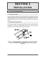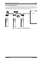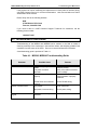
1
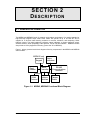
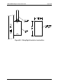
MSR42 /
MSRK42
MAGNETIC SWIPE
CARD READER
SERIES
TECHNICAL
MANUAL
an ISO 9001 certified
company
47102 Mission Falls Court,
Fremont, CA 94539-7818
(510) 360-7800
FAX (510) 360-7820
P/N 66109102001, Rev. B
© Copyright 1999 WSE
All rights reserved. Printed in the United States of America
MSR42, MSRK42 Magnetic Swipe Reader Series
LIMITED WARRANTY
WSE warrants to the original user the equipment manufactured by WSE as described
herein to be free from defects in material and workmanship for a period of one year from
the date of purchase by such user or fifteen (15) months from the date of shipment from
the factory, whichever is sooner, (command key / magnetic stripe card warranties differ,
see below *), provided:
I
WSE has been notified within such period by return of any alleged defective
equipment, free and clear of any liens and encumbrances to WSE or its
authorized dealer at the address specified, transportation prepaid; and
II
the equipment has not been abused, misused or improperly maintained
and/or repaired during such period; and
III
such defect has not been caused by ordinary wear and tear; and
IV
such defect is not a result of voltage surges/brownouts, lightning, water damage/flooding, fire, explosion, earthquakes, tornadoes, acts of aggression/war,
or similar phenomena; and
V
accessories used as integral to WSE systems have been approved by WSE
(e.g., coax, batteries, etc.); and
VI
the equipment has been installed, the installation supervised, or installation
tested by an authorized WSE dealer.
WSE MAKES NO OTHER WARRANTY, AND ALL IMPLIED WARRANTIES INCLUDING
ANY WARRANTY OF MERCHANTABILITY OR FITNESS FOR A PARTICULAR
PURPOSE ARE LIMITED TO THE DURATION OF THE EXPRESSED WARRANTY
PERIOD AS SET FORTH ABOVE.
WSE'S MAXIMUM LIABILITY HEREUNDER IS LIMITED TO THE PURCHASE PRICE
OF THE EQUIPMENT. IN NO EVENT SHALL WSE BE LIABLE FOR ANY CONSEQUENTIAL, INDIRECT, INCIDENTAL, OR SPECIAL DAMAGES OF ANY NATURE
ARISING FROM THE SALE OR USE OF THE EQUIPMENT.
Some states do not allow limitations on incidental or consequential damages or how long
an implied warranty lasts, so the above limitations may not apply. This warranty gives
specific legal rights; however, other rights which vary from state to state, may pertain.
* Analog command keys are warranted for 5 years; digital command key / magnetic
stripe card warranties vary. See product literature.
66109102001-Rev. B
i
MSR42, MSRK42
NOTICE
The MSR42 and MSRK42 series of Magnetic Card Swipe Readers sold by WSE have
been tested and found to comply with the limits for a Class B digital device, pursuant to
Part 15 of the FCC Rules. These limits are designed to provide reasonable protection
against harmful interference in a residential installation. This equipment generates, uses,
and can radiate radio frequency energy and, if not installed and used in accordance with
the instructions herein, may cause harmful interference to radio communications.
However, there is no guarantee that interference will not occur in a particular installation.
If this equipment does cause harmful interference to radio or television reception, which
can be determined by turning the equipment off and on, the user is encouraged to try to
correct the interference by one or more of the following measures:
•
Reorient or relocate the receiving antenna.
•
Increase the separation between the equipment and receiver.
•
•
Connect the equipment into an outlet on a circuit different from that to which the
receiver is connected.
Consult the dealer or an experienced radio/TV technician for help.
MSR42,MSRK42
ii
66109102001 Rev. B
MSR42, MSRK42 Magnetic Swipe Reader Series
TABLE OF CONTENTS
MSR42 / MSRK42 M AGNETIC CARD SWIPE READERS
SECTION 1 INTRODUCTION
1.1
PURPOSE........................................................................................................... 1-1
1.2
SCOPE................................................................................................................ 1-1
SECTION 2 DESCRIPTION
2.1
GENERAL INFORMATION ................................................................................ 2-1
2.2
CONFIGURATIONS ........................................................................................... 2-2
SECTION 3 INSTALLATION
3.1
LOCATION AND MOUNTING............................................................................ 3-1
3.1.1 Mounting the Reader................................................................................. 3-1
3.1.2 Weatherproofing the Reader..................................................................... 3-1
3.2
WIRING REQUIREMENTS................................................................................. 3-2
3.2.1 Reader Wiring ........................................................................................... 3-2
3.2.2 RS-485 Interface ....................................................................................... 3-2
3.2.3 12 or 24 Volt Operation ............................................................................. 3-3
3.2.4 Grounding the Reader .............................................................................. 3-4
3.2.5 DIP Switch Setting..................................................................................... 3-5
SECTION 4 MAINTENANCE AND TROUBLESHOOTING
4.1 MAINTENANCE........................................................................................................ 4-1
4.2 CUSTOMER SERVICE ............................................................................................. 4-1
4.3 TROUBLESHOOTING GUIDE ................................................................................. 4-2
APPENDICES
APPENDIX A Specifications ...........................................................................................A-1
APPENDIX B Product Identification................................................................................B-1
66109102001-Rev. B
iii
MSR42, MSRK42
MSR42,MSRK42
iv
66109102001 Rev. B
SECTION 1
INTRODUCTION
This manual provides basic information on the installation and operation of the WSE
MSR42 and MSRK42 Series Magnetic Swipe Card Readers. This information includes
specifications, a brief description of the operation, controls and indicators, relevant
installation data, and a troubleshooting guide.
NOTE: Changes or modifications to the equipment
described herein which are not expressly approved by
WSE can invalidate regulatory approvals, and may void
statutory authority of the user to operate the system.
1.1 PURPOSE
The purpose of this manual is to provide the information required for installing, operating,
and troubleshooting MSR42 and MSRK42 Series Magnetic Swipe Card Readers.
1.2 SCOPE
The information provided in this manual is intended for personnel who will be installing
MSR42 and MSRK42 Series Magnetic Swipe Card Readers, placing the units in
operation, and performing the troubleshooting procedures described herein. No repairs to
the units other than cleaning and switch settings are possible.
The information contained in this manual assumes that the person reading it is familiar
with access control and alarm monitoring technology and standard installation practices.
Thus, the manual is not intended to be a complete system installation guide or system
service manual for dealers or end-users. As such, the manual is a supplementary guide,
providing only information and data which is unique to MSR42 and MSRK42 Series
Magnetic Swipe Card Readers.
The information provided in this manual is not intended to either conflict with or
supplement the specific building codes, electrical codes, or safety codes to which any
given installation must conform.
This manual is organized as follows:
Section 1....................... INTRODUCTION
Section 2....................... DESCRIPTION
Section 3....................... INSTALLATION
Section 4....................... MAINTENANCE
Appendix A ................... SPECIFICATIONS
Appendix B ................... PRODUCT IDENTIFICATION
66109102001-Rev. B
1-1
MSR42, MSRK42
Introduction
MSR42, MSRK42
MSR42, MSRK42 Magnetic Swipe Readers Manual
1-2
661091020001-Rev. B
SECTION 2
DESCRIPTION
2.1 GENERAL INFORMATION
The MSR42 and MSRK42 family of magnetic card readers are designed for reading standard or
high-coercivity magnetic stripe cards. Each reader will operate at up to 28 volts DC and is
supplied in a die-cast metal housing resistant to corosion, abraision, and tampering. Other
features include: Two high brightness red/green status indicators, a tamper detection switch,
address switches, WSE proprietary S-Net protocol, and an RS-485 interface. MSRK42 readers
also provide a 12-key keypad for PIN entry, (hence the "K" in MSRK42).
Figure 1, below, gives the basic block diagram of the key components in the MSR42 and MSRK42
series readers.
MSRK42 only
Status
Keypad
Indicators
Controller
RS-485
Communications
Interface
S-Net
Address
Tamper
Protocol
Switches
Detect
Card
Reader
Micro-
Figure 1-1. MSR42, MSRK42 Functional Block Diagram.
66109102001-Rev. B
2-1
MSR42, MSRK42
Description
MSR42, MSRK42 Magnetic Swipe Readers Manual
2.2 CONFIGURATIONS
The MSR42 and MSRK42 Series Magnetic Swipe Card Readers are each available in two
configurations (weatherized and non-weatherized) as shown in Table 1-1 below.
Table 1-1. MSR42 and MSRK42 Configurations.
MSR42, MSRK42
Model
Part Number
MSR42-G
92422201000
MSR42-GW
92422211000
MSRK42-G
92422203000
MSRK42-GW
92422213000
2-2
Description
Swipe-style magnetic stripe
reader.
Swipe-style magnetic stripe
reader with weatherization.
Swipe-style magnetic stripe
reader with integral keypad.
Swipe-style magnetic stripe
reader with integral keypad
weatherization.
card
card
card
card
and
66109102001-Rev. B
SECTION 3
INSTALLATION
3.1 LOCATION AND MOUNTING
3.1.1 Mounting the reader:
Find a suitable location to anchor the reader mounting bracket. The mounting of the reader does
not require a junction box. However, rigid conduit is required for outdoor application. A single gang
junction box may used to provide transition to rigid conduit. If a single gang junction box is used,
a wall plate (optional) may be used to cover the junction box. The reader is then secured to the
mounting bracket using a screw. Refer to figures for reader dimensions and typical junction box
usage.
3.1.2 Weatherproofing the Reader:
The reader is rated for operation over extended temperature. However, if the reader is expected
to be exposed to weather, the weatherizing option (-GW) must be ordered. The option is
implemented in two parts. With the weatherizing option, the electronics are conformally coated
against moisture. A tube of dielectric grease is supplied for the installer.
Figure 3-1. Reader weatherization. Also shows key component locations.
(shown is the MSRK42-GW; the MSR42-GW does not have a keypad
connector)
66109102001-Rev. B
3-1
MSR42, MSRK42
MRS42, MSRK42 Magnetic Swipe Reader Series
Installation
3.2 WIRING REQUIREMENTS
3.2.1 Reader Wiring:
The reader provides an RJ-11 modular jack for easy field connection. A small piece of preterminated cable is supplied with each standard reader for field wiring. The pre-terminated cable
has non-standard colors. Refer to the pin numbers if the pre-terminated cable is not used. The
signal/wire assignment is different for each electrical interface. In any case, cable with wires of
24AWG or larger diameter are recommended for field wiring.
3.2.2 RS-485 Interface:
The RS-485 interface is two-wire half duplex. An on-board "End-of-Line" cable termination is
provided. If the reader is the last device on the bus, install a jumper to activate the terminator.
Refer to Figure 3-1. for the location of the terminator jumper. For communication reliability, a low
capacitance cable of 24AWG, twisted pair of wires, with 120 ohm characteristic impedance must
be used. Observe the following signal pairing: power/ground and TR+/TR-.
Figure 3-2 shows a typical RS-485 device wiring. Maintaining signal ground connection between
devices is essential for reliable communication.
MODULAR PLUG
6 (BLACK) GROUND
5 (ORANGE) NOT USED
4 (BROWN) NOT USED
3 (WHITE) RS-485+
2 (GREEN) RS-4851 (RED) +12 VDC*
Figure 3-2. Detail Showing The Modular Plug
MSR42,MSRK42
3-2
66109102001-Rev. B
MRS42, MSRK42 Magnetic Swipe Reader Series
Installation
3.2.3 12 or 24 Volt Operation:
The MSR42 and MSRK42 series readers can be operated from either 12 or 24 volt supplies by
using a special dropping resistor (pre-attached to the mounting plate at the factory). If 24 volt
operation (16-28 VDC) is required, consult Figure 3-3. If 12 volt operation (8-14 VDC) is required
consult Figure 3-4 instead.
(Red)
(Red)
(Green)
(White)
(Orange, Brown
not used)
Dropping Resistor
(behind plate)
RS-485+
RS-485-
(Black)
Common
(Red)
+28V
Figure 3-3. Connecting the reader to 24 volt supplies.
(Red)
+12V
(Red)
CUT
(Green)
(White)
(Orange, Brown
not used)
RS-485+
RS-485-
(Black)
Common
(Red)
Figure 3-4. Connecting the reader to 12 volt supplies.
66109102001-Rev. B
3-3
MSR42, MSRK42
MRS42, MSRK42 Magnetic Swipe Reader Series
Installation
3.2.4 Grounding the Reader:
To avoid having ESD (electro-static discharge) interfering with the operation of the reader, the
reader casing must be grounded. This can be accomplished be tying the mounting bracket to
earth ground locally (e.g. grounded conduit). Please consult Figure 3-5, below.
RS-485
Pair
Power & Return
Pair
Controller
Conduit
Ground
Figure 3-5. System Connections Diagram.
MSR42,MSRK42
3-4
66109102001-Rev. B
MRS42, MSRK42 Magnetic Swipe Reader Series
Installation
3.2.5 DIP switch setting:
The DIP switch on the MSR42, MSRK42 series readers is used to set the device address.
Each reader is equipped with DIP switches used to set a physical address. Refer to software
manuals for a detailed description of the address switches and their use. DIP switches are set by
moving the slide to on/off position using a small tool. (may be made from a paper clip). Remove
the top bracket to access the DIP switches.
Switch/Jumper Position
4 3 2 1 Device address
off off off off 0
off off off on 1
off off on off 2
off off on on 3
off on off off 4
off on off on 5
off on on off 6
off on on on 7
Switch/Jumper Position
4 3 2 1 Device address
on off off off 8
on off off on 9
on off on off A
on off on on B
on on off off C
on on off on D
on on on off E
on on on on F
Figure 3-6. Setting the Address Switch
66109102001-Rev. B
3-5
MSR42, MSRK42
MRS42, MSRK42 Magnetic Swipe Reader Series
MSR42,MSRK42
Installation
3-6
66109102001-Rev. B
SECTION 4
M A I N T E N A N C E A ND
TROUBLESHOOTING
4.1 MAINTENANCE
The readers are designed to provide continuous service with minimal routine
maintenance. However, contaminants (such as magnetic oxides from badges and dirt)
tend to accumulate on the read head. Without regular cleaning, these contaminants will
shorten the read head life and increase the probability of card read error. A maintenance
schedule should be developed based on the card reader environment (dirty or clean) and
the usage frequency (light traffic or heavy traffic). Readers placed in extremely dirty
environments may require daily cleaning.
Head cleaning may be done by using disposable, pre-saturated magnetic head cleaning
cards. These cards are readily obtainable from a number of sources (e.g. Clean Team
Co. 805/581-1000).
The reader exterior surface is covered with a high strength polymer and polyester
membrane. It may be cleaned with a soft cloth and mild detergent if required.
4.2 CUSTOMER SERVICE
4.2.1 PRODUCT IDENTIFICATION
If a problem with the reader occurs which might require consulting WSE Customer
Service, please note the model and serial numbers contained on the Product ID label.
This label is located on the rear of the reader behind the mounting plate, (and contains
other useful information).
an ISO 9001 certified company
MADE IN U.S.A.
MODEL: MSR42-G
MADE IN U.S.A.
P/N: 92422201000 REV: A
RATED: 25VDC-0.25W. SERIAL NO._______________
UL
R
LISTED 56Z7
ACCESS
CONTROL
294 UNIT
ACCESSORY
*FOR 24 V OPERATION, CONNECT PIN 1 TO
PIN R2; 24 V IS SUPPLIED TO PIN R1.
*FOR 12 V OPERATION, CONNECT PIN 1
DIRECTLY TO 12 V; R1 AND R2 ARE NOT USED.
PIN
FUNCTION
WIRE COLOR
1*
2
3
4
5
6
+12 VDC IN
RS-485(+)
RS-485(-)
NOT USED
NOT USED
COMMON
RED
GREEN
WHITE
BROWN
ORANGE
BLACK
R1
R2
+24 VDC
+12 VDC OUT
RED
RED
REFER TO MANUAL FOR INSTALLATION INSTRUCTIONS
4.2.1 PRODUCT RETURN POLICY
66109102001-Rev. B
4-1
MSR42, MSRK42
MSR42,MSKR42 Magnetic Swipe Reader Series
Troubleshooting And Maintenance
If the problem can not be rectified by the replacement of a faulty cable or interface wiring,
call WSE Customer Service for a Return Authorization. Units returned without a Return
Authorization will be refused.
Return faulty units to the following address:
WSE
47102 Mission Falls Court
Fremont, CA 94539-7818
If you need to talk to a WSE Customer Support Technician for assistance, call the
following phone number:
1-800-227-1667
4.3 TROUBLESHOOTING GUIDE
Troubleshooting of the MSR42 and MSRK42 series readers in the field is limited to
checking continuity of the conductors in the interface cables, and analyzing probable fault
conditions from the status of the LEDs. Be sure to consult software documentation.
A troubleshooting guide is provided in Table 4-1.
Table 4-1. MSR42, MSRK42 Troubleshooting Guide
Symptom
No Status LEDs are on;
Reader doesn't come on line.
Reader misreads cards
Reader functions but not
keypad.
MSR42,MSRK42
Possible Cause
Remedy
No power is getting to the
reader.
Low power at reader
terminals.
Unit not being addressed
properly.
Check power connections.
Observe polarity.
Verify that reader is wired for
correct voltage.
Check Address Switch. Make
certain software is properly
initialized.
RS-485 lines not connected
properly.
Dirty reader.
Check RS-485 wiring
Bad power, incorrect wiring
Check power, wiring.
Software not correctly
initialized.
Initialize software.
4-2
Clean read head.
66109102001-Rev. B
MSR42,MSKR42 Magnetic Swipe Reader Series
Troubleshooting And Maintenance
Table 4-1 Cont'd. MSR42, MSRK42 Troubleshooting Guide
Symptom
Reader seems to run hot.
Reader blinks every minute
66109102001-Rev. B
Possible Cause
Reader is being operated at a
voltage which is too high.
No problem.
4-3
Remedy
Verify unit is wired for the
correct voltage.
Normal Indication.
MSR42, MSRK42
MSR42,MSKR42 Magnetic Swipe Reader Series
MSR42,MSRK42
Troubleshooting And Maintenance
4-4
66109102001-Rev. B
APPENDIX A
SPECIFICA T IONS
The MRS42 and MSRK42 series readers are for use in low voltage, class 2 circuits.
Power:
Voltage Current Data:
Interface Bit rate Card:
Format Mechanical:
Dimension Weight Environmental:
Temperature Humidity -
66109102001, Rev. B
+12 VDC
80mA (50mA typical)
RS-485, two wires multidrop
9600 bps
75bpi, ANSI x4.16, Speed 3 to 50 ips
1.95" (50mm)W x 1.30" (33mm)H x 5.50" (140mm)L
10oz (284 g) nominal
-55 to +85 degrees C, storage
-40 to +75 degrees C, operating
0-95% RHNC, standard
100% (-GW options)
A-1
MSR42, MSRK42
MSR42, MSRK42 Series Magnetic Swipe Readers
MSR42, MSRK42
Appendix A
A-2
66109102001, Rev. B
APPENDIX B
DIMENSIONS
1.3 [33]
2X 0.18 [4.5]
MOUNTING HOLE
5.5
[140]
3.3
[84]
2.6
[66]
2.0 [50]
DIMENSION: INCH [mm]
Figure B-1. Reader Mounting Dimensions
Figure B-2. Optional Wall Plate Dimensions
66109102001, Rev. B
B-1
MSR42, MSRK42
MSR42, MSRK42 Magnetic Swipe Reader Series
Appendix B
Figure B-3. Fitting Rigid Conduit to Junction Box.
MSR42, MSRK42
B-2
66109102001, Rev. B