1
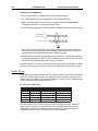
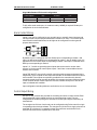
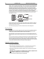
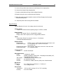
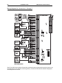
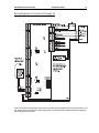
PW-5000
Two Reader Module
Installation Manual
Part Number: PW5KxR2
A division of Northern Computers, Inc.
TD1119 rev0100
2
Installation Guide
PW-5000 Two Reader Module
PW-5000 Two Reader Module
Installation Guide
3
Contents
Warnings and Cautions ........................................................................................ 4
Disclaimer ........................................................................................................... 6
Product Liability; Mutual Indemnification ................................................................ 6
Unpacking Procedure ........................................................................................... 6
Shipping Instructions ............................................................................................ 7
Limited Warranty .................................................................................................. 7
Confidentiality ..................................................................................................... 8
Description .......................................................................................................... 9
Set Up ................................................................................................................ 9
LED Operation .................................................................................................. 11
Power ............................................................................................................... 11
Communications ............................................................................................... 11
Reader Wiring ................................................................................................... 12
Alarm Contact Wiring ........................................................................................ 13
Control Output Wiring ....................................................................................... 13
Mounting Options ............................................................................................. 14
Suggested Installation Sequence ......................................................................... 14
Specification ...................................................................................................... 15
Wiring Diagram for Connectors 1through 7 ......................................................... 16
Wiring Diagram for Connectors 6 through 10 ...................................................... 17
4
Installation Guide
PW-5000 Two Reader Module
Warnings and Cautions
WARNING
Before installation, TURN OFF the external circuit breaker which supplies power to the
system.
Before connecting the device to the power supply, verify that the output voltage is within
specifications of the power supply.
Do not apply power to the system until after the installation has been completed.
Personal injury or death could occur, and the equipment could be damaged beyond
repair, if this precaution is not observed!
WARNING
Fire Safety and Liability Notice
Never connect card readers to any critical entry, exit door, barrier, elevator or gate
without providing an alternative exit in accordance with all fire and life safety codes
pertinent to the installation. These fire and safety codes vary from city to city and you
must get approval from local fire officials whenever using an electronic product to control
a door or other barrier. Use of egress buttons, for example, may be illegal in some cities.
In most applications, single action exit without prior knowledge of what to do is a life
safety requirement. Always make certain that any required approvals are obtained in
writing. DO NOT ACCEPT VERBAL APPROVALS, AS THEY ARE NOT VALID.
Northern never recommends using the N-1000, N-800, N-500, PW-2000, PW-5000,
EV-2000 or related products for use as a primary warning or monitoring system. Primary
warning or monitoring systems should always meet local fire and safety code requirements.
The installer must also test the system on a regular basis by instructing the end user in
appropriate daily testing procedures. Failure to test a system regularly could make installer liable for damages to the end user if a problem occurs.
WARNING
EARTH ground all enclosures, for proper installation.
WARNING
Use suppressors on all door strikes. Use S-4 suppressors for installation. Northern
Computers recommends only DC strikes.
The information in this document is subject to change without notice.
PW-5000 Two Reader Module
Installation Guide
5
CAUTION
IF ANY DAMAGE TO THE SHIPMENT IS NOTICED, A CLAIM MUST BE FILED WITH
THE COMMERCIAL CARRIER RESPONSIBLE.
CAUTION
Electro-static discharge can damage CMOS integrated circuits and modules.
To prevent damage always follow these procedures:
Use static shield packaging and containers to transport all electronic components,
including completed reader assemblies.
Handle all ESD sensitive components at an approved static controlled workstation. These
workstations consist of a desk mat, floor mat and an ESD wrist strap. Workstations are
available from various vendors.
NOTICE
This equipment has been tested and found to comply with the limits for a Class A digital
device, pursuant to part 15 of the FCC Rules. These limits are designed to provide
reasonable protection against harmful interference when the equipment is operated in a
commercial environment. This equipment generates, uses, and can radiate radio frequency energy and, if not installed and used in accordance with the instruction manual,
may cause harmful interference to radio communications. Operation of this equipment in
a residential area is likely to cause harmful interference in which case the user will be
required to correct the interference at his own expense.
NOTICE
This document and the data in it shall not be duplicated, used or disclosed to others for
procurement or manufacture, except as authorized by and with the written permission of,
Northern Computers, Inc. The information contained in this document or in the product
itself is considered the exclusive property and trade secrets of Northern Computers, Inc.
Copyright laws of the United States protect all information in this document or in the
software product itself.
NOTICE
Any use of this product is subject to the terms and acceptance of the Northern Computers, Inc. Software Agreement. Please request a copy from Northern Computers, Inc., and
review the agreement carefully.
6
Installation Guide
PW-5000 Two Reader Module
Disclaimer
Product Liability; Mutual Indemnification
In the event that a Customer receives a claim that a Product or any component thereof
has caused personal injury or damage to property of others, Customer shall immediately
notify Northern in writing of all such claims. Northern shall defend or settle such claims
and shall indemnify and hold Customer harmless for any costs or damages including
reasonable attorneys’ fees which Customer may be required to pay as a result of the
defective Product or the negligence of Northern, its agents, or its employees.
Customer shall hold harmless and indemnify Northern from and against all claims,
demands, losses and liability arising out of damage to property or injury to persons
occasioned by or in connection with the acts or omissions of Customer and its agents
and employees, and from and against all claims, demands, losses and liability for costs of
fees, including reasonable attorneys’ fees, in connection therewith.
Unpacking Procedure
CAUTION
If any damage to the shipment is noticed before unpacking, a claim must be filed with the
commercial carrier.
All containers should be opened and unpacked carefully in order to prevent damage to
the contents.
The following steps are used to unpack equipment in preparation for installation:
1. Open the container and remove the unit(s) and all packing material. Retain the
container and all packing materials. They may be used again for reshipment
of the equipment, if needed.
2. Inspect the contents for shortage. If items are missing items, contact the order entry
department.
3. Visually check contents. If damage is discovered, perform the following:
If shipping caused damage to the unit, a claim must be filed with the
commercial carrier.
If any other defect is apparent, call for a return authorization.
PW-5000 Two Reader Module
Installation Guide
7
Shipping Instructions
To ship equipment back to Northern Computers, Inc.:
1. Contact the customer service department before returning equipment.
When you call please have available:
• A description of the problem or reason you are returning the equipment.
• Your original purchase order number, invoice number and if the unit is still under
warranty.
• A new purchase order number if the unit is not under warranty
2. Obtain the Return Authorization Number (RMA) from the customer service
department.
3. Show the RMA number on all packages shipped. Packages, which are not marked with
an RMA number will be refused at the factory and returned to you COD.
4. Carefully pack the equipment for shipment. Use the original packing material whenever
possible
Limited Warranty
All Products sold or licensed by Northern include a warranty registration card which must
be completed and returned to Northern by or on behalf of the end user in order for
Northern to provide warranty service, repair, credit or exchange. All warranty work shall
be handled through Customer which shall notify Northern and apply for a Return Merchandise Authorization (RMA) number prior to returning any Product for service, repair,
credit or exchange. Northern warrants that its Products shall be free from defects in
materials and workmanship for a period of two years from date of shipment of the Product to Customer. The warranty on Terminals, Printers, Communications Products and
Upgrade kits is 90 days from date of shipment. Satisfaction of this warranty shall be
limited to repair or replacement of Products which are defective or defective under
normal use. Northern’s warranty shall not extend to any Product which, upon examination, is determined to be defective as a result of misuse, improper storage, incorrect
installation, operation or maintenance, alteration, modification, accident or unusual
deterioration of the Product due to physical environments in excess of the limits set forth
in Product manuals. THERE ARE NO WARRANTIES WHICH EXTEND BEYOND THIS
PROVISION. THIS WARRANTY IS IN LIEU OF ALL OTHER WARRANTIES WHETHER
EXPRESS, IMPLIED OR STATUTORY, INCLUDING IMPLIED WARRANTIES OF MERCHANTABILITY OR FITNESS FOR ANY PARTICULAR PURPOSE. NO REPRESENTATION OR WARRANTY OF THE DISTRIBUTOR SHALL EXTEND THE LIABILITY OR
RESPONSIBILITY OF THE MANUFACTURER BEYOND THE TERMS OF THIS PROVISION. IN NO EVENT SHALL NORTHERN BE LIABLE FOR ANY RE-PROCUREMENT
COSTS, LOSS OF PROFITS, LOSS OF USE, INCIDENTAL, CONSEQUENTIAL OR
SPECIAL DAMAGES TO ANY PERSON RESULTING FROM THE USE OF
NORTHERN’S PRODUCTS.
8
Installation Guide
PW-5000 Two Reader Module
Confidentiality
All software, drawings, diagrams, specifications, catalogs, literature, manuals and other
materials furnished by Northern relating to the design, use and service of the Products
shall remain confidential and shall constitute proprietary rights of Northern and Customer
agrees to treat such information as confidential. Customer shall acquire no rights in the
design of the Products or the related materials except to use such information solely for
the purpose of and only during the time it sells the Products. Customer shall not copy the
design of any of the Products or use or cause to be used any Product design or related
materials for its own benefit or for the benefit of any other party. The covenants contained
in this section shall remain effective throughout the term of this Agreement and thereafter
unless specifically waived by Northern in writing.
PW-5000 Two Reader Module
Installation Guide
9
Description
The Two Reader Board provides support for up to two access control doors by providing
connections for Wiegand or Clock/Data type readers, supervised inputs and relay outputs. This board can be rack mounted, in which case, only one edge is accessible for
wiring. Mounting the board flat increases the amount of available I/O slightly but also
significantly decreases the number of boards that can be mounted in one enclosure.
The I/O terminals are organized to support two doors. Starting at the bottom of the rackmount side of the board, the first connector provides power to the board. The next
connector provides communication with the Intelligent Controller (PW5KxIC). The next
set of terminals is used to connect reader 2. The next set of terminals is used to connect
the I/O typically associated with reader 2, namely the Door Status and REX status inputs
and the Door Lock and Lock Status relay outputs. Continuing up this edge the next two
connectors provide the reader and associated I/O terminals for reader 1. The last connector on the rack-mount edge provides terminals for two additional general-purpose
alarm inputs
When the board is mounted flat, two additional relay outputs and two additional generalpurpose alarm inputs are available along with two dedicated alarm inputs for cabinet
tamper and power fault detection on the opposite edge of the board.
The reader interface accepts a Wiegand signal of Data 1 and Data 0 or a Clock and Data
signal and provides 5VDC or 12VDC reader power, a tri-stated LED control and buzzer
control. Two of the six form-C relay outputs are sized for the inductive load of door locks
and the other four are designed to handle dry-circuit signals. All of the inputs are capable
of four-state supervision except the two dedicated inputs. Communication to the control
panel is accomplished via an RS-485 interface. This board requires 12VDC input power.
When communication to the control panel is lost this board can grant access based on
facility code only. General purpose outputs will retain the setting at the time communication was lost. Up to eight facility codes may be active in each PW5KxR2. Keypad input
must follow the reader input format and is in place of or multiplexed with the reader data.
Set Up
Jumper Settings:
N-1000-IV FFour
our
R eader Board
PB
Dipswitch Settings:
* = Default
Installation Guide
PW-5000 Two Reader Module
PW-5000 Two Reader Module
Installation Guide
11
LED Operation
The Reader board uses two on-board LEDs D79 & D80 to provide status information
during its Power-up sequence as well as normal operation.
MODE
Power-up
Sequence
LED
D79
LED
D80
DESCRIPTION
ON
OFF
Start Power-up, hardware setup
OFF
ON
Testing RAM
ON
ON
Testing ROM and completing initialization
FLASH
ON
LED D79 flashes 4 times after
Power-up is completed
This is the processor heart-beat LED. It flashes once
every second. A short ON time (~20% duty cycle)
indicates the board is off-line or has lost serial
communicationwith the Controller board. A long ON
time (~80% duty cycle) indicates the board is online
and communicating with the Controller board.
FLASH
Normal
Operation
FLASH
Flash when there is activity on its Serial Port.
In addition to the status LEDs, there are 6 additional relay status LEDs on board. When
any relay is energized or ON, its corresponding status LED will become ON also. The
LED will remain ON for as long as the relay is energized. The assignment for each relay
status LED is shown in the following table.
RELAY#
LED
1
D73
2
D75
3
D74
4
D76
5
D77
6
D78
Power
The Two Reader Board accepts 12VDC with an operating range of 10 to 16VDC and
consumes 400mA of current. Locate power source as close to this board as possible.
Connect power with minimum of 18AWG wire. The input voltage is regulated to 5VDC.
The regulated voltage or the 12VDC (pass through) is available for powering the readers.
The selection is made via jumpers and is available at both reader connectors.
NOTE: POLARITY for 12VDC power is important. Make sure the +12 VDC is
connected to the terminal labeled +12V and the return is connected to the terminal
labeled GND.
Communications
The Two Reader Board communicates to host controller via an RS-485 interface. The
interface allows for multi-drop communication of up to 4,000 feet (1,200 m) total per port.
Use two twisted pair (minimum 24AWG) with shield for communication. The default speed
of this port is 38.4Kbps but it can be downgraded to 19.2Kbps or 9.6Kbps if the line
conditions or receiving equipment require it (see jumper and DIP switch settings).
Installation Guide
PB
PW-5000 Two Reader Module
For Wiring to an RS-485 port:
1. TR+ is the plus side of the transmit and receive differential signal
2. TR- is the negative side of the transmit and receive differential signal.
3. GND is the signal ground. The wiring for this signal is required and NOT optional.
This signal must NOT be connected to chassis GND.
4. Use 24 AWG low capacitance, two twisted-pair, shielded cable (Belden 9842 or equiv.).
Orange/white stripe
+
White/orange stripe
—
Common
Note: For N-485 Communication Connections, twist the blue pair together and use as
the common; use the orange pair as your data pair, observing polarity. Connect the
external drain shield to the appropriate earth ground on one end.
5. When daisy-chaining RS-485 ports together connect the TR+ wires from the upstream
and downstream boards to the TR+ terminal and likewise, connect the TR– wires from
the upstream and downstream boards to the TR– terminal.
By factory default J1 is set open. If this board is the last board on the RS-485 bus, install
jumper J1 across both pins (closed). Closing J1 provides the bus termination required.
Reader Wiring
Each reader port supports a reader with TTL interface. Power to the reader is selectable
as 5VDC or 12VDC (pass-through). This selection is done via setting of jumpers J2 for
reader 1 and J3 for reader 2. Set jumper at position”5" for 5VDC or “12” for pass-through
12VDC. The factory defaults set J2 and J3 to “5”.
For wiring to a reader port:
Terminal
1
2
3
4
5
6
Typ Wire Color
Red
Brown
Yellow
White
Green
Black
Wiegand Reader
Power (5 or 12 Vdc)
LED control
Beeper Control
Data 1 Signal
Data 0 Signal
Common
Clock/Data Reader
Power (5 or 12 Vdc)
LED control
Beeper Control
Clock Signal
Data Signal
Common
The LED control terminal in each reader port can be configured via host software to
support one-wire single or bi-colored reader LED. An example of the most common
configuration is shown below. If Beeper control is not used, its terminal can be programmed to be the 2nd wire for the two-wire bi-colored reader LED.
PW-5000 Two Reader Module
Installation Guide
13
Single Wire Reader LED Control Configuration
LED Output->
High
Tri-Stated
Low
Single Color LED
LED On
LED Off
LED Off
Bi-Color LED
Green LED On
Both LEDs Off
Red LED On
To fully utilize each reader port, a 6-conductor cable (18AWG) is required. Reader port
configuration is set via host software.
Alarm Contact Wiring
Inputs 1 to 8 may be configured to use normally open or normally closed contacts and
non-supervised or supervised (with standard ±1 tolerance 1K ohm). Four of these inputs
have default functional definitions, but all eight can be configured to monitor generalpurpose alarm sensors.
1K
1K
1K
1K
NO
NC
1
2
3
4
By default, Input 1 is defined as the Door Status Input corresponding to reader 1 and
Input 2 is defined as the REX input corresponding to reader 1. Also by default, Input 3 is
defined as the Door Status Input corresponding to reader 2 and Input 4 is defined as the
REX input corresponding to reader 2.
Inputs 5, 6, 7, and 8 are general purpose inputs that can be used to monitor alarm
sensors or can be used as control inputs. Inputs 7 and 8 are not accessible when the
board is rack mounted.
Inputs TMP and PFL are typically used for monitoring cabinet tamper and power failure
respectively. These 2 inputs are not supervised and are not accessible when the board is
rack mounted. These inputs were primarily provided for the case when this board is
mounted remotely and can not take advantage of the tamper and power fail detect inputs
on the controller board. If these inputs are not used, install a short piece of wire at the
input to indicated safe condition.
Input configuration including debounce and hold time is set via host software.
Control Output Wiring
Six form-C relay contacts are provided for controlling door strike or other devices. Each
may be assigned to door-related functions or general-purpose output. They are
configurable as standard (energize to activate) or fail-safe (de-energize to activate) via
host software.
The energized or ON time of each relay can be configured using Pulse control for single
or repeating pulses via host software. The energized or ON time for a single pulse can be
extended up to 24 hours. For repeating pulses, the on/off time can be defined in 0.1
second increments and be repeated up to 255 times.
Installation Guide
PB
PW-5000 Two Reader Module
Relays 1 and 3 are rated for and normally used to control the door locks associated with
readers 1 and 2 respectively. While Relays 1 and 3 are sized to handle the typical loads
generated by electrical locks, load switching can cause abnormal contact wear and
premature contact failure. Switching of inductive loads (i.e., strike) also causes EMI
(electromagnetic interference) which may interfere with normal operation of other equipment. To minimize premature contact failure and to increase system reliability, contact
protection circuit is highly recommended. The following two circuits are suggested.
Locate the protection circuit as close to the load as possible (within 12 inches [30cm]), as
the effectiveness of the circuit will decrease as the distance from the load increases.
(See diagram to follow.)
Relays 2 and 4 are dry-circuit level signal relays typically used to indicate the status of
the door lock. Relays 5 and 6 are general-purpose relay outputs and are not available
when the board is rack mounted.
Use sufficiently large gauge of wires for the load current to avoid voltage loss.
Mounting Options
This board can be mounted on-edge in the rack-mount enclosure provided by Northern
Computers or it can be mounted flat against any surface using standoffs under the
mounting holes provided in each of the four corners of this board.
When this board is rack-mounted, the connectors for two general-purpose inputs, two
general-purpose outputs, and two dedicated inputs are not accessible and should not be
used.
The most common reason for mounting a board flat is that it is being installed remotely to
be located near the door(s) being monitored. In this case it will be mounted in its own
enclosure creating the need to monitor cabinet tamper and power fault detection inputs.
The two additional general-purpose inputs and outputs provided allow for the monitoring
of extra alarm sensors and control of local horns or other equipment.
Suggested Installation Sequence
1. Set Jumpers and DIP switches.
2. Mount this board in the appropriate enclosure – If this board is being mounted in a
rack, the component side of the board is to your right as you face the rack.
3. Connect the communications and power supply to the circuit boards with the Power
Supply Harness.
WARNING: DO NOT CONNECT THE POWER SUPPLY TO THE AC SOCKET UNTIL
ALL WIRING HAS BEEN INSTALLED AND RECHECKED.
4. Connect wiring to the reader interfaces as appropriate.
PW-5000 Two Reader Module
Installation Guide
15
5. Connect wiring to alarm input sensors or install jumper wire as appropriate.
6. Connect relay output wiring as appropriate.
7. Connect communications wiring to the Intelligent Controller.
8. Recheck wiring for correct connections and continuity.
9. When all boards have been installed, connect the Power Supply Cord for proper
connections and power.
10. Setup the panel controls using the host software.
Specification
The Two Reader is for use in low voltage, class 2 circuits only.
Primary power:
12VDC±10% 400mA with an operating range of 10VDC to 16VDC
Relay contacts:
Relays 1 & 3 outputs, Form-C, 5A @ 28VDC, resistive
Relays 2 & 4 & 5 & 6 outputs, Form-C, 2A @ 28VDC, resistive
Inputs:
8 supervised, End of Line resistors 1k ohm ± 1% tolerance
2 unsupervised dedicated inputs
Reader interface
Reader power
Reader LED output
Reader buzzer output
Reader data inputs
Communication:
RS-485
5VDC(5 - 6.2) or 12VDC (pass-through) 150mA max. each
TTL compatible, high > 3V, low < 0.5V, 5mA
source/sink max.
Open collector, 5VDC open circuit max. 10mA sink max.
TTL compatible inputs
9,600 to 38,400 bps
Wire requirements:
Power
1 twisted pair, 18AWG
RS-485:
24AWG, 4,000feet (1,200m) max., 2-twisted pair with shield (120Ω,
23pf) (Belden 9842 or equiv.)
Alarm inputs
1 twisted pair per input, 30 ohms max.
Outputs
As required for the load
Readers
6 conductors, 18AWG, 500 feet (150m) max. shield and drain
Mechanical:
Dimension
Weight
5.5" (140mm) W x 9" (229mm) L x 1" (25mm) H
12 oz. (340g) nominal
Environment:
Temperature
Humidity
–55°C to +85°C, storage, 0°C to +70°C, operating
0% to 95% RHNC
PB
Installation Guide
PW-5000 Two Reader Module
Wiring Diagram for Connectors 1 through 7
Note: For N-485 Communication Connections, twist the blue pair together and use as the common; use
the orange pair as your data pair, observing polarity. Connect the external drain shield to the appropriate earth ground on one end.
PW-5000 Two Reader Module
Installation Guide
17
Wiring Diagram for Connectors 6 through 10
Note: For N-485 Communication Connections, twist the blue pair together and use as the common; use
the orange pair as your data pair, observing polarity. Connect the external drain shield to the appropriate earth ground on one end.
A division of Northern Computers, Inc.
SHAPING SECURITY THROUGH CREATIVE SOLUTIONS
5007 South Howell Avenue • Milwaukee, WI 53207 USA
Tel (414) 769-5980 • (800) 323-4576