1
Contact Us Covers all models. Includes a fill-in maintenance chart. Contents Overview Installation Operation See separate Service Manual Maintenance ProLINE-RoadRunner Owner’s Manual Troubleshooting TM Glossary PN 096-0240-005H Index 1 Overview 1 General Descriptions • TaskLink™ • Safety Precautions • Specifications 2 Installation 2 Unpack • Setup • Power Up 3 Operation 3 Keypad Operation • Menus • Programming • Yields • Updates Order form for Service Manual (See separate Service Manual for: 4 • Replacement Procedures • Basic Spare Parts • Self-Service Spare Parts • Order Forms) 5 Maintenance 5 Preventive Schedule • Diagnostics • Sign-off Chart 6 Troubleshooting 6 Error Messages • Other Problems Glossary Index Sales and Technical Support contact numbers are after the index. G I Data I/O has endeavored to ensure that the information in this document is accurate and complete. Data I/O assumes no liability for errors, or for any incidental, consequential, indirect, or special damages, including, without limitation, loss of use, loss or alteration of data, delays, or lost profits or savings, arising from the use of this document or the product which it accompanies. No part of this document may be reproduced or transmitted in any form or by any means, electronic or mechanical, for any purpose, without written permission from Data I/O Corporation. Data I/O order forms may be reproduced for internal use only. Data I/O is a registered trademark of Data I/O Corporation, as are ProLINE‐RoadRunner and TaskLink. Data I/O Corporation acknowledges the trademarks of other organizations for their respective products or services mentioned in this document. The Technical Documentation Department also acknowledges the RoadRunner team members for their efforts in supporting the flow of information into this manual. We are interested in your comments. email: [email protected] © 2004–2010 Data I/O Corporation All rights reserved Contents 096-0240-005H 1 • Overview RoadRunner is — 1–1 Warning and Caution Notes 1–3 Overall System Description 1–4 Development of the Programming Instructions for a Job Control Panel 1–5 Blank Devices 1–5 Tape Advancement 1–5 Robotic System 1–6 Programmer Module 1–8 Output Conveyor 1–10 Reject Bin 1–10 TaskLink’s Handshake with RoadRunner 1–11 PCMCIA Memory Card Capacity Requirements Safety 1–12 Precautions for Safe Operation 1–14 Specifications [Assembleon] 1–15 Specifications [Fuji QP, IP, XP] 1–16 Specifications [Fuji NXT, AIM] 1–17 Specifications [MYDATA] 1–18 Safety Features 1–4 1–11 1–12 Specifications [Panasonic CM20, CM120, CM301] 1–19 Specifications [Panasonic CM401, CM402, CM602, DT401] 1–20 Specifications [Panasonic MSF, MCF, MPAV2B, MPAG3] 1–21 Specifications [Siemens, XLF, SIPLACE X] 1–22 Specifications [Universal GSM] 1–23 Specifications [Universal Genesis] 1–24 Data I/O • ProLINE-RoadRunner Owner’s Manual • 096-0240 i 2 • Installation Unpacking the RoadRunner 2–1 Removing the Shipping Bracket 2–2 Mounting the RoadRunner 2–3 Mounting RoadRunner [Assembleon ACM] 2–4 Mounting RoadRunner [MYDATA MY9, MY12, MY15, MY19] 2– 6 Mounting RoadRunner [Fuji QP242, QP351, IP3, XP142E] 2–8 Mounting RoadRunner [Fuji NXT, AIM] 2–10 Mounting RoadRunner [Panasonic MSF, MCF, MPA] 2–11 Mounting RoadRunner [Panasonic CM20, CM120, CM301] 2– 12 Mounting RoadRunner [Panasonic CM401, CM402, DT] 2–14 Mounting RoadRunner [Siemens 80F4, 80F5, F, S, HS] 2–17 Mounting RoadRunner [Siemens SIPLACE X2, X3, X4, X4i] 2– 20 Mounting RoadRunner [Universal GSM1,GSM2, Genesis] 2–22 Installing the Reject Bin 2–24 Making the Necessary Connections 2–25 Electrical Input Requirements 2–25 Pneumatic Input Requirements 2–26 Connecting the Communications Cable 2–28 Applying Power for the First Time 2–30 Turning Power On 2–30 Configuring for Network Communication 2–31 Configuring TaskLink 2–31 Configuring RoadRunner 2–31 3 • Operation Operator Functions 3–1 Basic Operator Steps 3–1 Turning On System Power 3–2 Menus Available to the System Operator 3–3 Keypad Operation 3–4 Setting Up RoadRunner for a Programming Job Programming Devices 3–18 Miscellaneous Settings via the Menu 3–23 Supervisor Functions 3–24 Menus Available to the System Supervisor Setting Operational Parameters 3–27 Setting System Parameters 3–31 Network Settings 3–34 Configuration 3–34 Robot Diagnostics 3–35 Programmer Diagnostics 3–36 ii 3–5 3–24 Data I/O • ProLINE-RoadRunner Owner’s Manual • 096-0240 Event Log 3–37 Results 3–37 Session Data Log 3–38 4 • Service information . . . . . . is in a separate manual, with its own Table of Contents and Index. 4–1 5 • Maintenance Tools Required 5–1 Preventive Maintenance Schedule 5–2 Lubricating the Ball Screw 5–3 Diagnosing with the Adapter Board 5–5 Running Diagnostics on a Programmers 5–5 Electrical Equipment Disposal Notice 5–7 RoHS for China 5–7 Maintenance Sign-off Charts 5–8 Notes: 5–9 6 • Troubleshooting Colored Lamp Significance 6–1 Resolving Problems 6–2 Testing the Programmer 6–2 Viewing Errors 6–2 Clearing Jammed Device Tape 6–2 Disabling and Enabling a Socket 6–3 Error Messages 6–4 No Change in Lamps 6–4 Yellow Lamp is On 6–4 Blue Lamp is On 6–7 Unlisted Error Messages 6–14 Problems, but no Error Message 6–15 Schematics 6–22 Pneumatic Schematic 6–22 Electrical Schematic 6–23 Data I/O • ProLINE-RoadRunner Owner’s Manual • 096-0240 iii Glossary • Glossary of Terms Alphabetical List of Terms Glossary–1 Index • Index Alphabetical Index Listing Index–1 iv Data I/O • ProLINE-RoadRunner Owner’s Manual • 096-0240 Chapter 1 1Overview RoadRunner is — ProLINE-RoadRunner™ is a compact, portable, automated programming and handling system that mounts directly to a Surface Mount Technology (SMT) Placement Machine. Easy to use and small enough to fit within the profile of a component feeder, the ProLINE-RoadRunner programs and delivers devices to the pick region of placement machines, allowing our customers to integrate device programming and placement. In this chapter you’ll learn about RoadRunner’s compact, component units called modules, safety precautions, ESD, and stopping in an emergency. You can also learn about the latest programmer architecture and High Force Conversion Kits. RoadRunner is available for many different SMT Placement machines; some are shown on the next page. Other models for each SMT machine may also available, such as the RoadRunner-XLF (Extra Large Format). XLF RoadRunners run devices up to 32 mm Wide x 32 mm Long x 6 mm High. The Standard RoadRunner programs devices up 21.65 mm W x 15 mm L x 3 mm H. The Three Parts of a ProLINE-RoadRunner System PCMCIA Card RoadRunner TaskLink Figure 1-1—The ProLINE-RoadRunner System is TaskLink Software, a Job Card, and the RoadRunner [Universal Model shown] (Notebook PC not included.) Data I/O • ProLINE-RoadRunner Owner’s Manual • 096-0240 [updated Mar2010] 1—1 Overview • RoadRunner is — •• 1 Fuji QP, IP Assembleon XLF on Siemens F5 Siemens Fuji NXT, AIM Universal GSM Panasonic MSF MYDATA Panasonic CM20 Panasonic CM, DT 1—2 Figure 1-2—Various Standard RoadRunner Models attached to corresponding SMT machines and one XLF RoadRunner. Data I/O • ProLINE-RoadRunner Owner’s Manual • 096-0240 [updated Mar2010] Overview • Warning and Caution Notes •• 1 Warning and Caution Notes Special paragraphs in this manual warn about potentially hazardous situations and recommend safe practices to help avoid them. ! WARNING Indicates conditions that can cause personal injury or serious monetary loss. A warning looks like this. CAUTION: Indicates conditions that can cause damage to equipment. A caution looks like this. They are included to help the operator use the system safely and efficiently. Key to Symbols Used in this Manual General warning. Calls your attention to general caution and warning notes. Electrostatic Discharge (ESD) may cause damage. Discharge static against a common ground. High voltage. Turn power off before removing electronics cover. Crush hazard. Keep hands away from moving parts. b Compressed air. Point air hoses away from body. Always wear approved eye protection. Heavy equipment. Use caution. May require two people. Or, mount properly using approved hardware. Equipment can tip over (such as feeder carts with some RoadRunners on them). Remove RoadRunner before moving cart. Collision hazard.Some situations can cause machinery to collide with object or people items are installed incorrectly. Data I/O • ProLINE-RoadRunner Owner’s Manual • 096-0240 [updated Mar2010] 1—3 Overview • Overall System Description •• Development of the Programming Instructions for a Job 1 Overall System Description The ProLINE-RoadRunner System consists of RoadRunner (which attaches to SMT Placement machines), TaskLink™ software for Windows-based PCs, and a PCMCIA card (PC-Card). TaskLink is needed to create programming jobs for RoadRunner. PC-Cards store jobs and contain job statistics. Using prepared programming instructions and blank devices, RoadRunner picks, programs, and delivers the devices to the pick region of an SMT Placement machine. NOTE: This manual refers to the RoadRunner, TaskLink software, and a job card as the “ProLINE-RoadRunner,” or the “ProLINE-RoadRunner System.” The term “RoadRunner” then, is used to mean the hardware unit that attaches to the SMT placement machine. Development of the Programming Instructions for a Job Programming instructions are developed using TaskLink™ for Windows.® The instructions are stored on PCMCIA Type I or II job cards that are formatted for RoadRunner. A RoadRunner operator can start a job by inserting a job card and pressing the Start button on the control panel. Start Figure 1-3—The RoadRunner Control Panel and Display Screen 1—4 Data I/O • ProLINE-RoadRunner Owner’s Manual • 096-0240 [updated Mar2010] Overview • Overall System Description •• Tape Advancement 1 Control Panel The Control Panel is a keypad and display that provides a User Interface (UI) to the RoadRunner programming system. The main function of the Control Panel is to accept input (commands) from the operator via the keypad, while providing visual or auditory feedback to the operator regarding status of the system. Blank Devices Before starting a job, the operator must mount a reel of tape containing blank devices onto the RoadRunner or placement machine cart. Once the device tape is threaded into the RoadRunner and a job is started, the RoadRunner will pick devices from the tape and advance the tape automatically. Periodically, new device tape must be loaded and the cover tape take-up reel must be emptied. Tape Advancement Tape advancement includes three functions—advancing the device tape, separating the cover tape from the device tape, and collecting the cover tape. Tape-In Module A stepper motor drives a sprocket that advances the device tape via sprocket holes along the tape’s edge. Tape movement is stepped, allowing the tape to stop each device directly under the pick point. The empty device tape is expelled at the front of the RoadRunner or near the front below the conveyor. Different Tape-In Modules are available for different width device tape, and there is an adjustable module that accommodates 16, 24, and 32 mm tape. The XLF models also have an adjustable Tape-In Module that accommodates 32 and 44 mm tape. Cover Tape Module The Cover Tape Module winds up used cover tape so it can be disposed of by the operator. A DC motor, synchronized with the tape advance motor, drives the Take-up Reel that winds up the separated cover tape. The cover tape is threaded around a peel bar that separates it from the device tape. Some cover tape is sticky enough that it will affix directly to the reel, while other cover tape must be fastened to the reel with a piece of adhesive tape. Refer to Figure . Data I/O • ProLINE-RoadRunner Owner’s Manual • 096-0240 [updated Mar2010] 1—5 Overview • Overall System Description •• Robotic System 1 Cover Tape Motor Cover Tape Take-Up R eel Figure 1-4—Loading Cover Tape [Siemens model shown]. Note that on XLF Models the cover tape rotation is in the opposite direction. Robotic System A four-probe Pick and Place (PNP) head driven by a linear stage ball screw constitutes RoadRunner’s robotic system. NOTE: Some RoadRunner models are designed to operate with fewer than four probes. A stepper motor controls ball screw movement which produces travel in the horizontal axis. Air cylinders control individual probe up and down motion. Together, these components pick, collect, and place devices as directed. The standard robotic system uses the “collect and place” principle to: • pick one device at a time from the device tape until four (or less depending on the Socket Adapter) devices are collected • place the devices into the programming sockets, one at a time • pick the programmed devices out of the sockets, one at a time • gang place up to four devices on the conveyor belt, or place failed devices into the Reject Bin. RoadRunners, including the large format RoadRunners (XLF), may operate with one, two, three, or four probes to collect and place devices, determined by the Socket Adapter. 1—6 Data I/O • ProLINE-RoadRunner Owner’s Manual • 096-0240 [updated Mar2010] Overview • Overall System Description •• Robotic System 1 PNP Head (& Cover– some models) Serial number label Linear Stage Module Programmer Module Figure 1-5—PNP Head Positioned above Programming Sockets [Fuji Model Shown] Pick and Place Head The Pick and Place Head (PNP) is the portion of the robotic system responsible for picking, collecting, and placing devices. It houses four pneumatic cylinders, and four hollow probes for air flow. The pneumatic cylinders feature spring return to the upper position. The probes incorporate a measure of compliance to allow contacting all sizes of devices without applying excessive force. The probes have rubber tips which must be kept clean in order to create adequate suction against the device. The PNP Assembly will not move until all four probes are in their up position. Linear Stage A linear stage—consisting of a stepper motor, encoder and ball screw— moves the PNP head linearly to accommodate the following positions: RoadRunner runs at slow speed when the Robotic Cover (safety shield) is not in place. • device tape pick point, • reject bin, • programmer sockets, • and programmer sockets. The linear stage motor receives signals from the motion controller via an amplifier. The PNP head is, itself, part of the Linear Stage Module. Data I/O • ProLINE-RoadRunner Owner’s Manual • 096-0240 [updated Mar2010] 1—7 Overview • Overall System Description •• Programmer Module 1 Figure 1-6—Pick and Place Assembly with Probes. Not shown: PNP Cover and the Precisor (XLF models do not use either). Vacuum Probes The rubber-tipped probes use vacuum produced by the Pneumatic Module to pick up devices. The probes also deliver a puff of air to release the devices. Vacuum sensors detect whether a device is present at the end of each probe. Device Placement Precision On standard RoadRunners (not XLF), each probe brings its device into contact with the alignment plate, called a precisor, to center the device on the probe before placing it into a programming socket. Precisors are generally device-package specific. Programmer Module The Programmer Module writes data into the devices. From a mechanical standpoint, it consists of device-specific sockets on an adapter and an actuator. The Programmer Module is responsible for: • opening the sockets • ID checking, blank-checking, continuity-checking and erasing the devices, if selected • writing data to the devices • verifying the data written to devices Opening the Sockets The device sockets on the adapter are normally closed. To open the sockets, pneumatic cylinders pull the Actuator Plate down. Once the sockets are loaded they close again, keeping the device leads in contact with the socket pins. 1—8 Data I/O • ProLINE-RoadRunner Owner’s Manual • 096-0240 [updated Mar2010] Overview • Overall System Description •• Programmer Module 1 High Force Actuation Prior to October 2007, four pneumatic cylinders were used to pull the Actuator Plate down. Since 2007, and the introduction of our HIC Socket Adapters, more force is required. High Force Conversion Kits are available allowing pre-2007 RoadRunners to use HIC Adapters. (Later models actuate HIC Adapters without conversion kits.) The following charts lists upgrade kits available for new programmers as well as higher force actuation. Sales Part Description Description RR-PROG MOD HF KIT FCII –Upgrade to High Force FlashCORE II programmer. RR-PROG HF UPGRADE KIT –Upgrade to High Force actuation only. RR-FCIII UPGRADE KIT –Upgrade to FlashCORE III programmers. Programming Devices FlashCORE II is the second iteration of this programming architecture. Contact Data I/O for FlashCORE Upgrade Kits. The RoadRunner programmer architecture, called FlashCORE, was developed specifically for very high-speed programming of Flash memory devices. Up to four devices are programmed simultaneously according to the instructions from the particular job on the job card. Job cards must be programmed using TaskLink for Windows. In addition to programming the devices, the programmer can perform a continuity check, a blank check, an electronic identification check, and a data verification. If any of these tests fail, the programmer illuminates the red LED in front of the socket(s) containing the failed device(s) and signals the robotic system to place the device into the reject bin rather than on the conveyor belt. Programming yield statistics are displayed on the screen. If a job is paused or ended, the statistics are written to the job card. Programming sockets are a wear item, and therefore, must be replaced periodically. Socket manufacturers provide expected socket-insertion life cycles. See “Preventive Maintenance Schedule” on page 5-2 for recommendations for RoadRunner. Data I/O • ProLINE-RoadRunner Owner’s Manual • 096-0240 [updated Mar2010] 1—9 Overview • Overall System Description •• Reject Bin 1 Output Conveyor Successfully programmed devices are removed from the programming sockets by the PNP Head and placed on the conveyor belt, then delivered to the SMT Placement machine’s pick position. The conveyor module includes a conveyor belt, a sensor that determines if devices are at the SMT pick point, and in some models the path for the empty device tape. The conveyor runs momentarily when a job is started to determine if there are any unwanted devices on the belt (from a previous job). The belt stops when a device is sensed at the SMT machine pick point, when the robot places a new set of devices on the belt, or when it times out. Reject Bin Devices that have failed programming, as determined by data verification, are dropped into a Reject Bin inside RoadRunner. The Reject Bin has a sensor that indicates when it is full by displaying a message on the keypad screen; “Empty Reject Bin.” 1—10 Data I/O • ProLINE-RoadRunner Owner’s Manual • 096-0240 [updated Mar2010] Overview • TaskLink’s Handshake with RoadRunner •• PCMCIA Memory Card Capacity Requirements 1 TaskLink’s Handshake with RoadRunner TaskLink for Windows is the software program used to create programmer instructions for the RoadRunner system. It consists of various utilities for selecting • the device to program, • the data file to write to the device, and • special programming options specific to the device. NOTE: The term task refers to a device programming objective being defined with TaskLink. The term job refers to a set of instructions for programming a specific number of devices with the RoadRunner. TaskLink must be installed on a Windows-based PC and configured to work with the RoadRunner programmer. To install TaskLink, see the instructions on the CD. Parallel ATA-2 is an interface standard for the connection of storage devices and uses a PCMCIA form factor: 85.6 × 54 × 3.3 mm 68 pin dual row connecting interface. A PCMCIA memory card drive capable of reading and writing to Parallel ATA-2 specification must be available to the computer being used. For more about PCMCIA drives see “PCMCIA Memory Card Capacity Requirements” below. See TaskLink’s on-screen Help (for RoadRunner) to create a RoadRunner Job. PCMCIA Memory Card Capacity Requirements ProLINE-RoadRunner uses a 68 pin PCMCIA (PC) Card to transfer job configuration and device programming data from TaskLink software (running on a PC) to RoadRunner. The PC Card is used to store job files, statistics/event log, algorithms, and even system updates. Ensure the card you use will hold your device image data plus 130 KB for statistics and event files. The general formula used to calculate required PC card size for one job; 256 KB+device size+130 KB Remember that 1 MB = 1024 KB. In general, add 256 KB to device size (for system files). To calculate each job size, sum all jobs together and add 130 KB for statistics and event files. For example, when creating a card with two jobs, one for a 28F800 (1 MB) device and one for a 29LV160 (2 MB) device you would need: (256 KB+1024 KB)+(256 KB+2048 KB)+130 KB = 3714 KB = 3.8 MB Use a 4 MB minimum ATA card for this configuration. Data I/O • ProLINE-RoadRunner Owner’s Manual • 096-0240 [updated Mar2010] 1—11 Overview • Safety •• Safety Features 1 NOTE: The system operator can only access a single job from the PCMCIA memory card. If there is more than one job on the card, then the last job selected by the system supervisor is the one used. It is recommended that only one job be placed on each PC Card to avoid operator confusion. NOTE: Data I/O recommends that a 2 MB minimum card be used for even a single job. CAUTION: PCMCIA Cards for use with RoadRunner must be formatted with FAT 16. The current Windows default is FAT 32. The card must be x40 speed. For information on card reader/writers that work with your computer system and ProLINE-RoadRunner, see Card Reader/Writers on our Web site at: http://www.dataio.com/support/ and then: 1. Click Knowledge Base Search. 2. Sign in, or click Use the Knowledge Base without signing in. 3. In the Keywords field, type Card Reader. 4. Click Search. 5. Click the document name to open it. Safety Safety Features The RoadRunner has several safety systems to reduce the likelihood of personal injury and machine damage during operation. These systems include: 1. 1—12 Safety Shields and Interlocks During RoadRunner operation the metal and plastic safety shield (Robotics Cover) covers the operating area to protect operators from Data I/O • ProLINE-RoadRunner Owner’s Manual • 096-0240 [updated Mar2010] Overview • Safety •• Safety Features 1 injury. If the shield is opened, robot movement will reduce to halfspeed. ! WARNING Risk of injury. System robotics can injure your hands or fingers. Do not operate the RoadRunner with covers removed. When working inside the RoadRunner, turn the power off. 2. Emergency Stop Button (E-Stop) When the E-Stop button (located on the keypad) is pressed, the RoadRunner automatically removes power from all motion motors. The blue status lamp illuminates, and the programmer completes its programming cycle. The programmed devices will remain in their sockets. Figure 1-7—Emergency (movement) Stop Button ! WARNING Shock hazard. Do not use the E-Stop button to turn off power to the RoadRunner. The E-Stop button does not completely remove power from the machine. Only power to the motion motors is shut off. Power is still applied to all of the other electronic systems. CAUTION: The Emergency Stop button does not stop the SMT Placement equipment. The Emergency Stop condition will not be cleared until the E-Stop button is restored to its run position. To restore the button to the run position, turn the Emergency Stop button clockwise until it springs back to its full height. Data I/O • ProLINE-RoadRunner Owner’s Manual • 096-0240 [updated Mar2010] 1—13 Overview • Precautions for Safe Operation •• – 1 Precautions for Safe Operation The RoadRunner System has been designed for safe and efficient operation. The system can be dangerous if the RoadRunner safety features and precautions in this manual are ignored. To avoid possible personal injury or damage to the equipment, please observe the following practices: Electrostatic Discharge The circuit boards inside RoadRunner are susceptible to electrostatic discharge (ESD), which can damage the circuitry. Also, devices processed through the RoadRunner are very sensitive to static and can be damaged by accidental electrostatic discharge while being handled. The easiest way to prevent damage from ESD is to make sure a common static potential (ground) exists between static-sensitive devices or components, their environment, and the operator. • Only trained personnel should install, maintain, repair, or troubleshoot this system. • Do not operate the ProLINE-RoadRunner unless you have been thoroughly trained, and have read and understand the instructions in this manual, particularly those that describe the system’s safety features. • Do not use ProLINE-RoadRunner for any application other than its intended use. • Do not operate the system if the guards or safety devices are not in their normal operating positions. • Do not operate RoadRunner with any of the outer sheet metal panels removed. • Do not operate RoadRunner while servicing, replacing, or adjusting any component unless directed to do so in this manual. Make sure that the RoadRunner is properly shut down before performing any of these operations. • Do not place any part of your body near or in the direct path of moving parts. • Do not disable or attempt to defeat any of the protective safety features of this system. Personal injury or equipment damage can occur if any safety systems on RoadRunner are disabled. If you suspect that a safety feature of the RoadRunner is damaged or malfunctioning, stop using the RoadRunner immediately and contact Data I/O Customer Service or a local Data I/O approved service representative. • Use extra caution when working around the RoadRunner’s Output Belt. RoadRunner’s safety shields do not cover or fully enclose the output conveyor. It is possible that an operator’s hands, other body parts, or loose clothing can get caught or pinched in it. • Wearing hearing protection is recommended while operating the RoadRunner. Sound pressure levels may exceed 85 decibels. • Shut off the pressurized air or disconnect the air hose before servicing pneumatic parts. Perform all repairs at an ESD-safe workstation. – 1—14 Data I/O • ProLINE-RoadRunner Owner’s Manual • 096-0240 [updated Mar2010] Overview • Specifications [Assembleon] •• – 1 Specifications [Assembleon] FACILITIES AC input voltage requirements 100-240 V~ ; 50/60 Hz (single phase) AC Input Power 100 W (max) Air requirements @ 2dm3/s (4.0scfm) .52 MPa (75±2psi) Air Inlet tube (varies) 6 mm (.24 in.) & 8 mm (.31 in.) OD min. MODELS SUPPORTED Assembleon models supported (with Assembleon Universal Adapter) ACM, ACM Micro, AQ-1, AQ-2, D9 DIMENSIONS Width 78 mm (3.1 in.) Weight (net) 17 kg (38 lbs) Length with 33 cm (13 in.) reel 124.5 cm (49 in.) Approximate length protruding from SMT machine 63.5 cm (25 in.) Height with 33 cm (13 in.) reel 49.5 cm (19.5 in.) Input tape width supported 16 mm; 24 mm; 32 mm (optional: 12 mm, 32 mm-Large Format) DEVICE OUTPUT PLACEMENT (at SMT pick point) Output placement linear repeatability ±.25 mm Output placement rotational repeatability ±5° ENVIRONMENT Operating temperature range 20–40°C (68–104°F) Temperature stabilization time after transportation ≥ 8h Humidity 5–90% Data I/O • ProLINE-RoadRunner Owner’s Manual • 096-0240 [updated Mar2010] 1—15 Overview • Specifications [Fuji QP, IP, XP] •• – 1 Specifications [Fuji QP, IP, XP] FACILITIES AC input voltage requirements 100-240 V~ ; 50/60 Hz (single phase) AC Input Power 100 W (max) Air requirements @ 2dm3/s (4.0scfm) .52 MPa (75±2 psi) Air Inlet tube (varies) 6 mm (.24 in.) & 8 mm (.31 in.) OD min. MODELS SUPPORTED Fuji models supported QP242, IP3, QP351, XP142E DIMENSIONS Width 78 mm (3.1 in.) Weight (net) 14 kg (32 lbs) Length with 33 cm (13 in.) reel 91.5 cm (36 in.) Approximate length protruding from SMT machine 0 cm (0 in.) Height with 33 cm (13 in.) reel 49 cm (19.5 in.) Input tape width supported 16 mm; 24 mm; 32 mm (optional: 12 mm, 32 mm-Large Format) DEVICE OUTPUT PLACEMENT (at SMT pick point) Output placement linear repeatability ±.25 mm Output placement rotational repeatability ±5° ENVIRONMENT 1—16 Operating temperature range 20–40°C (68–104°F) Temperature stabilization time after transportation ≥ 8h Humidity 5–90% Data I/O • ProLINE-RoadRunner Owner’s Manual • 096-0240 [updated Mar2010] Overview • Specifications [Fuji NXT, AIM] •• – 1 Specifications [Fuji NXT, AIM] FACILITIES AC input voltage requirements 100-240 V~ ; 50/60 Hz (single phase) AC Input Power 100 W (max) Air requirements @ 2 dm3/s (4.0 scfm) .52 MPa (75±2 psi) Air Inlet tube 8 mm (.31 in.) OD min. MODELS SUPPORTED Fuji models supported NXT, AIM DIMENSIONS Width 78 mm (3.1 in.) Weight (net) 17 kg (37 lbs) Length with 33 cm (13 in.) reel 104.4 cm (41.1 in) Approximate length protruding from SMT machine 74 cm (29 in). Height with 33 cm (13 in.) reel 49 cm (19.5 in) Input tape width supported 16 mm; 24 mm; 32 mm (optional: 12 mm, 32 mm-Large Format) DEVICE OUTPUT PLACEMENT (at SMT pick point) Output placement linear repeatability ±.25 mm Output placement rotational repeatability ±5° ENVIRONMENT Operating temperature range 20–40°C (68–104°F) Temperature stabilization time after transportation ≥ 8h Humidity 5–90% Data I/O • ProLINE-RoadRunner Owner’s Manual • 096-0240 [updated Mar2010] 1—17 Overview • Specifications [MYDATA] •• – 1 Specifications [MYDATA] FACILITIES AC input voltage requirements 100-240 V~ ; 50/60 Hz (single phase) AC Input Power 100 W (max) Air requirements @ 2dm3/s (4.0scfm) .52 MPa (75±2 psi) Air Inlet tube (varies) 6 mm (.24 in.) & 8 mm (.31 in.) OD min. MODELS SUPPORTED MYDATA models supported MY9, MY12, MY15, MY19 DIMENSIONS Width 78 mm (3.1 in.) without SMT Adapter Weight (net) 16.5 kg (36.3 lbs) without SMT Adapter Length with 33 cm reel 120.1 cm (47.3 in.) without SMT Adapter Approximate length protruding from SMT Feeder Table outer edge 59.2 cm (23.3 in.) includes 33 cm reel Height 49.4 cm (19.5 in.) includes 33 cm reel Input tape width supported 16 mm; 24 mm; 32 mm (optional: 12 mm, 32 mm-Large Format) DEVICE OUTPUT PLACEMENT (at SMT pick point) Output placement linear repeatability ±.25 mm Output placement rotational repeatability ±5° ENVIRONMENT 1—18 Operating temperature range 20–40°C (68–104°F) Temperature stabilization time after transportation ≥ 8h Humidity 5–90% Data I/O • ProLINE-RoadRunner Owner’s Manual • 096-0240 [updated Mar2010] Overview • Specifications [Panasonic CM20, CM120, CM301] •• – 1 Specifications [Panasonic CM20, CM120, CM301] FACILITIES AC input voltage requirements 100-240 V~ ; 50/60 Hz (single phase) AC Input Power 100 W (max) Air requirements at 2dm3/s (4.0scfm) .52 MPa (75±2 psi) Air Inlet tube 8 mm (.31 in.) OD min. MODELS SUPPORTED Panasonic models supported CM20, CM120, CM301 DIMENSIONS Width 7.8 cm (3.1 in.) Weight (net) 14 kg (30.9 lbs) Length with 33 cm (13 in.) reel 84 cm (33 in) Approximate length protruding from SMT machine (including reel) 61 cm (24 in) Height with 33 cm (13 in.) reel 50 cm (19.7 in.) Input tape width supported 16 mm; 24 mm; 32 mm (optional: 12 mm, 32 mm-Large Format) DEVICE OUTPUT PLACEMENT (at SMT pick point) Output placement linear repeatability ±.25 mm Output placement rotational repeatability ±5° ENVIRONMENT Operating temperature range 20–40°C (68–104°F) Temperature stabilization time after transportation ≥ 8h Humidity 5–90% Data I/O • ProLINE-RoadRunner Owner’s Manual • 096-0240 [updated Mar2010] 1—19 Overview • Specifications [Panasonic CM401, CM402, CM602, DT401] •• – 1 Specifications [Panasonic CM401, CM402, CM602, DT401] FACILITIES AC input voltage requirements 100-240 V~ ; 50/60 Hz (single phase) AC Input Power 100 W (max) Air requirements @ 2dm3/s (4.0scfm) .52 MPa (75±2 psi) Air Inlet tube 8 mm (.31 in.) OD min. MODELS SUPPORTED Siemens models supported CM401, CM402, CM602, DT401. A Panasonic Feeder Bank Adapter and Host Feeder are required. DIMENSIONS Width 7.8 cm (3.1 in.) Weight (net) 15 kg (33 lbs) Length without reel 99 cm (39 in.) Approximate length protruding from SMT machine 55 cm (21.6 in.) Height without reel 56 cm (22 in.) Input tape width supported 16 mm; 24 mm; 32 mm (optional: 12 mm, 32 mm-Large Format) DEVICE OUTPUT PLACEMENT (at SMT pick point) Output placement linear repeatability ±.25 mm Output placement rotational repeatability ±5° ENVIRONMENT 1—20 Operating temperature range 20–40°C (68–104°F) Temperature stabilization time after transportation ≥ 8h Humidity 5–90% Data I/O • ProLINE-RoadRunner Owner’s Manual • 096-0240 [updated Mar2010] Overview • Specifications [Panasonic MSF, MCF, MPAV2B, MPAG3] •• – 1 Specifications [Panasonic MSF, MCF, MPAV2B, MPAG3] FACILITIES AC input voltage requirements 100-240 V~ ; 50/60 Hz (single phase) AC Input Power 100 W (max) Air requirements at 2dm3/s (4.0scfm) .52 MPa (75±2 psi) Air Inlet tube 8 mm (.31 in.) OD min. MODELS SUPPORTED Panasonic models supported MSF, MPAV2B, MPAG3,MCF DIMENSIONS Width 78 mm (3.1 in.) Weight (net) 16 kg (35 lbs) Length with 33 cm (13 in.) reel 115 cm (45.25 in.) Approximate length protruding from SMT machine 76 cm (30 in.) Height with 33 cm (13 in.) reel 49.5 cm (19.5 in.) Input tape width supported 16 mm; 24 mm; 32 mm (optional: 12 mm, 32 mm-Large Format) DEVICE OUTPUT PLACEMENT (at SMT pick point) Output placement linear repeatability ±.25 mm Output placement rotational repeatability ±5° ENVIRONMENT Operating temperature range 20–40°C (68–104°F) Temperature stabilization time after transportation ≥ 8h Humidity 5–90% Data I/O • ProLINE-RoadRunner Owner’s Manual • 096-0240 [updated Mar2010] 1—21 Overview • Specifications [Siemens, XLF, SIPLACE X] •• – 1 Specifications [Siemens, XLF, SIPLACE X] FACILITIES AC input voltage requirements 100-240 V~ ; 50/60 Hz (single phase) AC Input Power 100 W (max) Air requirements @ 2dm3/s (4.0scfm) .52 MPa (75±2 psi) Air Inlet tube (varies) 6 mm (.24 in.) & 8 mm (.31 in.) OD min. MODELS SUPPORTED STD & XLF models supported SIPLACE X models supported • 80F4; 80F5, F, S, HF, HS Series*, D Series*, X3* • SIPLACE X2, X3, X4, X4i model —— DIMENSIONS — model —— model —— Standard XLF models SIPLACE X Width 78 mm (3.1 in.) 99.5 mm (3.9 in.) 78 mm (3.1 in.) (unaffected by SMT Adapter) Weight (net) 15 kg (33 lbs) 21 kg (45 lbs) 19 kg (41 lbs) includes SMT Adapter Length (unaffected by reel) Length including 33 cm reel Length including 33 cm reel 99 cm (39 in.) 118 cm (46.5 in.) 120.1 cm (47.3 in.) includes SMT Adapter Approximate length protruding from SMT Feeder Table outer edge 56 cm (22 in.) 76.2 cm (30 in.) includes (33 cm) reel 70.6 cm (27.8 in.) includes 33 cm reel Height 56 cm (22 in.) (unchanged by reel) 52 cm (20.5 in.) includes (33 cm) reel 49.4 cm (19.5 in.) includes 33 cm reel Input tape width supported 16 mm, 24 mm, 32 mm (optional: 12 mm) 16 mm, 24 mm, 32 mm, 44 mm (Opt: 12 mm) 16 mm, 24 mm, 32 mm (optional: 12 mm) DEVICE OUTPUT PLACEMENT (at SMT pick point) Output placement linear repeatability ±.25 mm Output placement rotational repeatability ±5° ENVIRONMENT Operating temperature range 20–40°C (68–104°F) Temperature stabilization time after transportation ≥ 8h Humidity 5–90% * Supported using S-type feeder table in feeder positions 2 & 4, except X3 in 4 only. 1—22 Data I/O • ProLINE-RoadRunner Owner’s Manual • 096-0240 [updated Mar2010] Overview • Specifications [Universal GSM] •• – 1 Specifications [Universal GSM] FACILITIES AC input voltage requirements 100-240 V~ ; 50/60 Hz (single phase) AC Input Power 100 W (max) Air requirements @ 2dm3/s (4.0scfm) .52 MPa (75±2 psi) Air Inlet tube (varies) 6 mm (.24 in.) & 8 mm (.31 in.) OD min. MODELS SUPPORTED Universal models supported GSM1; GSM2 DIMENSIONS Width 78 mm (3.1 in.) Weight (net) 17 kg (38 lbs) Length with 33 cm (13 in.) reel 124. 5cm (49 in.) Approximate length protruding from SMT Placement machine 80.8 cm (31.8 in.) Height with 33 cm (13 in.) reel 49.5 cm (19.5 in.) Input tape width supported 16 mm; 24 mm; 32 mm (optional: 12 mm, 32 mm-Large Format) DEVICE OUTPUT PLACEMENT (at SMT pick point) Output placement linear repeatability ±.25 mm Output placement rotational repeatability ±5° ENVIRONMENT Operating temperature range 20–40°C (68–104°F) Temperature stabilization time after transportation ≥ 8h Humidity 5–90% Data I/O • ProLINE-RoadRunner Owner’s Manual • 096-0240 [updated Mar2010] 1—23 Overview • Specifications [Universal Genesis] •• – 1 Specifications [Universal Genesis] FACILITIES AC input voltage requirements 100-240 V~ ; 50/60 Hz (single phase) AC Input Power 100 W (max) Air requirements @ 2dm3/s (4.0scfm) .52 MPa (75±2 psi) Air Inlet tube 8 mm (.31in.) OD min. MODELS SUPPORTED Universal models supported Genesis DIMENSIONS Width 78 mm (3.1 in. Weight (net) 18.2 kg (40 lbs) Length with 33 cm (13 in.) reel 124. 5 cm (51.8 in.) Approximate length protruding from SMT Placement machine 72.1 cm (28.4 in.) Height with 33 cm (13 in.) reel 49.5 cm (19.5 in.) Input tape width supported 16 mm; 24 mm; 32 mm (optional: 12 mm, 32 mm-Large Format) DEVICE OUTPUT PLACEMENT (at SMT pick point) Output placement linear repeatability ±.25 mm Output placement rotational repeatability ±5° ENVIRONMENT 1—24 Operating temperature range 20–40°C (68–104°F) Temperature stabilization time after transportation ≥ 8h Humidity 5–90% Data I/O • ProLINE-RoadRunner Owner’s Manual • 096-0240 [updated Mar2010] Chapter 2 2Installation For the Reject Bin location see Figure 19 on page 3-21 or see “Reject Bin” in the Service Manual.” Unpacking and installing the RoadRunner is easy. It is delivered preassembled with a few exceptions. There are four items that need to be installed onto the RoadRunner: • the Socket Adapter, • Actuator Plate, • and Precisor (except on XLF models) that are described in Chapter 3, • and the Reject Bin which is described in this chapter. Some RoadRunners require an additional item to install to adapt it to the SMT machine. These are noted in the Mounting Instructions in this chapter where they apply. All that is required to operate the programmer is an SMT machine position and two external facilities. (You may also need to install some pneumatic components into your air supply line.) ! WARNING Lifting heavy objects improperly could injure you. The standard RoadRunner and shipping box weighs 26 kg (58 lbs) maximum. The XLF model RoadRunner and box weighs 32 kg (70 lbs) maximum. This chapter includes: • • • • • • • Removing the Shipping Bracket Proper mounting procedure for each model Installing the Reject Bin Pneumatic and Electrical requirements Connecting the Communications Cable (applicable models) Applying power Setting the network configuration (optional). Unpacking the RoadRunner The RoadRunner is transported in an antistatic bag packaged in a heavy corrugated box with foam padding. On arrival, ensure that there is no damage to the exterior of the box since this may also indicate damage to the machine inside. If there is significant damage to the box or shipping container, contact your local Data I/O approved service representative immediately. Data I/O • ProLINE-RoadRunner Owner’s Manual • 096-0240 [updated Mar2010] 2—1 Installation • Removing the Shipping Bracket •• It takes about eight hours for the RoadRunner temperature to stabilize to the new environment after shipping. Do not run a job before RoadRunner has stabilized—the chassis should be at room temperature. After opening the box containing the RoadRunner, inspect for damage that may have occurred during shipment. Two shock indicators have been applied to the shipping box for your assurance that the RoadRunner has not been mishandled during shipping. They are orange plastic indicators, 2 inches (50.8 mm) long applied with adhesive backing. If the RoadRunner has sustained sufficient impact (25G) during shipment, the groove on either side of the label will be black or a color darker than the body color. See Figure 2-1. If this is the case, contact your local Data I/O Support Representative immediately. Both grooves the same color as the body indicate that no impact has occurred. 2 Figure 2-1—Shock Indicator is Indicating that an Impact has Occurred (Left Side, black arrow [<]) A list of contents is included in the box. Check that you have received everything on the list. (Additional items ordered, such as spare parts, are shipped in a separate box.) Removing the Shipping Bracket RoadRunners shipped prior to 2009 had a bracket securing the PNP Head. It must be removed before operating the RoadRunner. If the bracket was reinstalled for subsequent shipping, you should check that it is again removed prior to operating the RoadRunner. It is the brightly painted bracket that can be seen extending out from under the PNP Head Cover, if installed. Refer to the figure below. 2—2 Data I/O • ProLINE-RoadRunner Owner’s Manual • 096-0240 [updated Mar2010] Installation • Mounting the RoadRunner •• Ball Screw Rail HousBall Screw Yellow Shipping Bracket Top View Side Head Cover (some PNP Head Figure 2-2—Shipping Bracket (Plan and Elevation Views) To remove the Shipping Bracket: 1. Remove the Robotics Cover by grasping the outer edges and pulling. 2. If your PNP head has a cover, remove the cover by pulling it straight off the magnetized head bracket. 3. Unscrew the socket head screw securing the Shipping Bracket to the PNP Head. 4. Unscrew the two screws securing the Shipping Bracket to the Ball Screw housing. 5. Remove the Shipping Bracket. Mounting the RoadRunner The RoadRunner is designed to mount to the SMT machine feeder table. Multiple RoadRunners may be mounted on the same SMT machine. CAUTION: Heavy weight. Use great care when mounting RoadRunner to the feeder table. It is heavy, and dropping it can cause serious damage to RoadRunner and anything it falls upon. Use only approved hardware to mount RoadRunner to the SMT feeder table. Data I/O • ProLINE-RoadRunner Owner’s Manual • 096-0240 [updated Mar2010] 2—3 2 Installation • Mounting the RoadRunner •• Mounting RoadRunner [Assembleon ACM] Mounting RoadRunner [Assembleon ACM] 2 NOTE: The Assembleon RoadRunner must be mounted to a Universal Feeder Table Adapter. Install a Universal Feeder Table Adapter onto the ACM machine before continuing. Look ahead for mounting instructions for your specific model of RoadRunner. Also, the ACM upper feeder guide must be used. NOTE: When selecting slot positions for RoadRunner, consider that access to it is from the right side. To mount the RoadRunner onto the SMT machine feeder bank, perform the following: 1. Hold the RoadRunner level and rest the nose on the feeder bank. Ensure that the guide under the conveyor settles into a slot. Figure 2-3—Mounting the RoadRunner onto a Feeder Bank Changer. CAUTION: Feeder carts might become unstable. The RoadRunner can also be mounted on feeder carts and feeder test stands. However, some carts/stands were not designed for the heavy overhang of the RoadRunner and may tip over easily, especially if the wheels encounter bumps. Use caution; don’t use (and do label) unsafe carts. 2—4 Data I/O • ProLINE-RoadRunner Owner’s Manual • 096-0240 [updated Mar2010] Installation • Mounting the RoadRunner •• Mounting RoadRunner [Assembleon ACM] 2. Level the RoadRunner while continuing to support the weight, and slide it forward as far as it will go. 3. Make sure the RoadRunner feels securely supported before letting go. It will latch to the feeder bank under its own weight. 2 Latch Figure 2-4—Slide the RoadRunner Forward 4. Check again that the RoadRunner is secure. The RoadRunner is now mounted to the feeder bank. Data I/O • ProLINE-RoadRunner Owner’s Manual • 096-0240 [updated Mar2010] 2—5 Installation • Mounting the RoadRunner •• Mounting RoadRunner [MYDATA MY9, MY12, MY15, MY19] Mounting RoadRunner [MYDATA MY9, MY12, MY15, MY19] 2 CAUTION: Heavy weight. Use great care when mounting RoadRunner to the feeder table. It is heavy, and dropping it can cause serious damage to RoadRunner and anything it falls upon. Use only approved hardware to mount RoadRunner to the SMT feeder table. To mount the Feeder Bank Adapter and RoadRunner onto a MYDATA MY-Series Assembly Machine: 1. Slide the supplied Feeder Bank Adapter onto the assembly machine feeder table at the desired slot. Push it forward as far as it will go. Figure 2-5—Install the Feeder Bank Adapter onto the SMT Machine separately. 2. Holding RoadRunner at a slight angle, slide it under the hook on the Feeder Bank Adapter so that the RoadRunner centering plate teeth engage the pin next to the hook. pin hook Top View Into SMT Figure 2-6—Installing RoadRunner onto the Feeder Bank Adapter. A dowel on the Adapter (circled) mates with the RoadRunner nose. 2—6 Data I/O • ProLINE-RoadRunner Owner’s Manual • 096-0240 [updated Mar2010] Installation • Mounting the RoadRunner •• Mounting RoadRunner [MYDATA MY9, MY12, MY15, MY19] 3. Lower RoadRunner letting the Adapter dowels mate up with the bushings in the RoadRunner. Refer to Figure 2-6. 4. Make sure that RoadRunner is secure. 5. For first time use at this SMT machine, adjust the Feeder Bank Adapter to align the pick points. 5a. Compare the SMT pick point to the RoadRunner pick point. If adjustment is required, continue. Otherwise, go to step 6 below. Figure 2-7—Devices center at the pick point marks on the RoadRunner conveyor. 5b. Loosen four screws on top of the Feeder Bank Adapter. Loosen four screws (only one shown) Adjust Figure 2-8—Adjusting the pick point. 5c. Screw the end screw in or out until the RoadRunner pick point is aligned with the SMT pick point. 5d. Retighten the four top screws. 6. Connect the communications cable. For more, see “MYDATA Communications” on page 2-28. Data I/O • ProLINE-RoadRunner Owner’s Manual • 096-0240 [updated Mar2010] 2—7 2 Installation • Mounting the RoadRunner •• Mounting RoadRunner [Fuji QP242, QP351, IP3, XP142E] Mounting RoadRunner [Fuji QP242, QP351, IP3, XP142E] CAUTION: Heavy weight. Use great care when mounting RoadRunner to the feeder table. It is heavy, and dropping it can cause serious damage to RoadRunner and anything it falls upon. Use only approved hardware to mount RoadRunner to the SMT feeder table. 2 To mount the RoadRunner onto the Multi-Feeder Unit (MFU), complete the following procedure: 1. Align and push the communications cable into a connector in the MFU. NOTE: When selecting slot positions for RoadRunner, consider that access to it is from the right side. Figure 2-9—The Communications Cable is inserted into the MFU. NOTE: The assembly machine pick point will correspond with the MFU slot number that is in-line with the conveyor belt. Make sure conveyor belt is closest to the slot number that the communication cable is plugged into. 2. 2—8 Hold the RoadRunner at a slight nose-down angle and rest the nose on the feeder bank. Ensure that the guide under the conveyor settles into a slot by pushing the RoadRunner gently to one side until you feel resistance. Data I/O • ProLINE-RoadRunner Owner’s Manual • 096-0240 [updated Mar2010] Installation • Mounting the RoadRunner •• Mounting RoadRunner [Fuji QP242, QP351, IP3, XP142E] 2 Figure 2-10—The RoadRunner mounted onto a Multi Feeder Unit (MFU) CAUTION: Feeder carts might become unstable. RoadRunner can also be mounted on feeder carts and feeder test stands. However, some carts/stands were not designed for the heavy overhang of RoadRunner and may tip over easily, especially if the wheels encounter bumps. Use caution; don’t use (and do label) unsafe carts. 3. Slide RoadRunner forward until it comes to a solid stop. The nose will fit under the lip on the MFU. 4. Lower RoadRunner fully to ensure that the steel angle under the conveyor settles into the spring clamp on the MFU. Spring Clamp Figure 2-11—The angle bracket on RoadRunner fits into the MFU Spring Clamp. 5. Ensure that RoadRunner is secure. RoadRunner is now mounted to the Fuji MFU. Data I/O • ProLINE-RoadRunner Owner’s Manual • 096-0240 [updated Mar2010] 2—9 Installation • Mounting the RoadRunner •• Mounting RoadRunner [Fuji NXT, AIM] Mounting RoadRunner [Fuji NXT, AIM] CAUTION: Heavy weight. Use great care when mounting RoadRunner to the feeder table. It is heavy, and dropping it can cause serious damage to RoadRunner and anything it falls upon. Use only approved hardware to mount RoadRunner to the SMT feeder table. 2 To mount RoadRunner onto a Feeder Table: NOTE: When selecting slot positions for RoadRunner, consider that access to it is from the right side. Also, do not use the four left-most slots on the table or the two right-most slots. 1. Hold RoadRunner, one hand in the handhold and one under the Conveyor, so the Conveyor overlaps the Feeder Table by 40 mm and is above a slot. Figure 2-12—Mounting RoadRunner onto the SMT Feeder Table. 2—10 2. Lower RoadRunner allowing the nose to rest on the Feeder Table. Ensure that it settles into a slot. 3. Still holding the handhold, slide RoadRunner forward as far as it will go. RoadRunner locks into place. Data I/O • ProLINE-RoadRunner Owner’s Manual • 096-0240 [updated Mar2010] Installation • Mounting the RoadRunner •• Mounting RoadRunner [Panasonic MSF, MCF, MPA] Mounting RoadRunner [Panasonic MSF, MCF, MPA] CAUTION: Heavy weight. Use great care when mounting RoadRunner to the feeder table. It is heavy, and dropping it can cause serious damage to RoadRunner and anything it falls upon. Use only approved hardware to mount RoadRunner to the SMT feeder table. NOTE: When selecting slot positions for RoadRunner, consider that access to it is from the right side. To mount RoadRunner for Panasonic onto a feeder cart: 1. While holding RoadRunner level, let the nose rest on the cart. Line up the hook with a slot. Figure 2-13—Mounting RoadRunner onto a feeder cart. 2. Slide RoadRunner forward as far as it will go. The communication path will connect automatically. 3. Ensure that RoadRunner is secure. Data I/O • ProLINE-RoadRunner Owner’s Manual • 096-0240 [updated Mar2010] 2—11 2 Installation • Mounting the RoadRunner •• Mounting RoadRunner [Panasonic CM20, CM120, CM301] Mounting RoadRunner [Panasonic CM20, CM120, CM301] CAUTION: Heavy weight. Use great care when mounting RoadRunner to the feeder bank. It is heavy, and dropping it can cause serious damage to RoadRunner and anything it falls upon. Use only approved hardware to mount RoadRunner to the SMT feeder bank. 2 NOTE: When selecting slot positions for RoadRunner, consider that access to it is from the right side. Also, on STM machine CM20 make sure the RoadRunner does not interfere with the handle on the machine cover. To mount RoadRunner onto the Feeder Bank: 1. Hold RoadRunner at slight nose-down angle and rest the nose on the feeder bank. 2. Align the nose with a slot on the feeder bank. Ensure RoadRunner engages with one of the slots and the corresponding pin/rib as you push forward. 3. When it stops going forward push down on the RoadRunner to engage the rollers on the bottom of the conveyor into the groove on the bank. See the figure below. Rollers Figure 2-14—Rollers on the bottom of the Conveyor Module fit into the groove on the feeder bank. 4. 2—12 Check that the RoadRunner is stable by rocking it cautiously. Data I/O • ProLINE-RoadRunner Owner’s Manual • 096-0240 [updated Mar2010] Installation • Mounting the RoadRunner •• Mounting RoadRunner [Panasonic CM20, CM120, CM301] 2 Figure 2-15—RoadRunner/Panasonic mounted on the Feeder Bank. To remove the RoadRunner, lift up on the operator end and pull back out of the SMT machine. Data I/O • ProLINE-RoadRunner Owner’s Manual • 096-0240 [updated Mar2010] 2—13 Installation • Mounting the RoadRunner •• Mounting RoadRunner [Panasonic CM401, CM402, DT] Mounting RoadRunner [Panasonic CM401, CM402, DT] CAUTION: Heavy weight. Use great care when mounting RoadRunner to the feeder bank. It is heavy, and dropping it can cause serious damage to RoadRunner and anything it falls upon. Use only approved hardware to mount RoadRunner to the SMT feeder bank. 2 NOTE: When selecting slot positions for RoadRunner, consider that access to it is from the right side. A Panasonic Feeder Bank Adapter and Host Feeder unit must be mounted to the SMT Feeder Bank prior to mounting the RoadRunner. Then the RoadRunner can be mounted onto the Adapter. The steps for connecting the communication cable follow. To mount the Feeder Bank Adapter and Host Feeder: 1. Align the Feeder Bank Adapter with the numbered feeder slots and slide it forward to engage the alignment features. Push the Feeder Bank Adapter forward as far as it will go. 2. Tighten the set screw to lock in place. See Figure 2-16. 3. Slide the Host Feeder onto the feeder slot immediately left of the Feeder Bank Adapter. Mounting and Alignment features: Hook Dowel Set screw Figure 2-16—Panasonic Feeder Bank Adapter and Host Feeder mounted on the CM402 SMT Feeder Bank 4. 2—14 Push the Host Feeder forward as far as it will go. Data I/O • ProLINE-RoadRunner Owner’s Manual • 096-0240 [updated Mar2010] Installation • Mounting the RoadRunner •• Mounting RoadRunner [Panasonic CM401, CM402, DT] To mount RoadRunner onto the Panasonic Feeder Bank Adapter: 1. Slide RoadRunner under the hook on the Feeder Bank Adapter so that the RoadRunner centering plate teeth engage the pin next to the hook. See Figure 2-17. 2 RoadRunner Centering Plate Figure 2-17—The Panasonic Feeder Bank Adapter has a hook and a pin. 2. Lower RoadRunner so that the Feeder Bank Adapter dowel mates with the guide bushing on the RoadRunner conveyor. See Figure 2-18. Figure 2-18—The dowel on the Adapter (circled) mates with Roadrunner. 3. Verify that RoadRunner is secure. To connect the Communication Cable into the Host Feeder: 1. Correctly orient the connector (the red dot will be on top) and plug it into RoadRunner. The socket is located on the back side—facing the SMT feeder table. 2. Orient and plug the other end of the cable into the Host Feeder. 3. Screw in the two connector screws. See Figure 2-19. Data I/O • ProLINE-RoadRunner Owner’s Manual • 096-0240 [updated Mar2010] 2—15 Installation • Mounting the RoadRunner •• Mounting RoadRunner [Panasonic CM401, CM402, DT] 2 Figure 2-19—RoadRunner is mounted and the Communication Cable is plugged into the Panasonic Host Feeder unit. 2—16 Data I/O • ProLINE-RoadRunner Owner’s Manual • 096-0240 [updated Mar2010] Installation • Mounting the RoadRunner •• Mounting RoadRunner [Siemens 80F4, 80F5, F, S, HS] Mounting RoadRunner [Siemens 80F4, 80F5, F, S, HS] CAUTION: Heavy weight. Use great care when mounting RoadRunner to the feeder table. It is heavy, and dropping it can cause serious damage to RoadRunner and anything it falls upon. Use only approved hardware to mount RoadRunner to the SMT feeder table. NOTE: When selecting slot positions for RoadRunner, consider that access to it is from the right side. To mount the RoadRunner onto the machine feeder table, perform the following: CAUTION: There are different hooks. Use of the wrong hook will cause mounting and device pick problems. Use the hook with black knob or the hook with the Hex socket screw as shown on the label located on the RoadRunner Conveyor. You might also have a black hook which is for the taller, later model of RoadRunner. The new Hex-socket screw hook and the black anodized hook are interchangeable. 1. Slide the proper mounting hook around a pin on the feeder table where the RoadRunner is to be mounted. Refer to Figures 2-20, 2-21, 2-22, and 2-23 for placement details. Data I/O • ProLINE-RoadRunner Owner’s Manual • 096-0240 [updated Mar2010] 2—17 2 Installation • Mounting the RoadRunner •• Mounting RoadRunner [Siemens 80F4, 80F5, F, S, HS] 2 Latest Hook Hook for early RoadRunners Figure 2-20—Positioning the RoadRunner Mounting Hook—ensure the correct hook is used. Figure 2-21—The Hex socket-screw-hook for taller RoadRunners [Siemens]. Edge of RoadRunner RoadRunner teeth Mount- into SMT RoadRunAlignment Plate Figure 2-22—Hook Location Relative to standard RoadRunner Placement. (not XLF models). Top View 2—18 Data I/O • ProLINE-RoadRunner Owner’s Manual • 096-0240 [updated Mar2010] Installation • Mounting the RoadRunner •• Mounting RoadRunner [Siemens 80F4, 80F5, F, S, HS] Edge of RoadRunner RoadRunner teeth Mount- 2 into SMT RoadRunner Hook Alignment Plate Figure 2-23—Hook Location Relative to RoadRunner-Siemens XLF Placement. Top view. ! WARNING RoadRunner is heavy and can fall if the correct mounting hook is not properly attached. Falling can injure you or damage RoadRunner. The hook is absolutely required. Do not attempt to mount RoadRunner onto the feeder table without the hook installed onto the table. 2. Tighten the hook thumbscrew or the 3 mm socket-head adjustment screw, as applicable. 3. Slide RoadRunner under the hook so that the teeth engage the pin next to the hook as shown in Figure 2-22 and below in Figure 2-24. Teeth on RoadRunner Siemens Figure 2-24—Early model Siemens RoadRunner Mounted onto the SMT Feeder Table [Siemens] 4. Test to ensure RoadRunner is secure. RoadRunner is now mounted to the SMT feeder table. Data I/O • ProLINE-RoadRunner Owner’s Manual • 096-0240 [updated Mar2010] 2—19 Installation • Mounting the RoadRunner •• Mounting RoadRunner [Siemens SIPLACE X2, X3, X4, X4i] Mounting RoadRunner [Siemens SIPLACE X2, X3, X4, X4i] CAUTION: Heavy weight. Use great care when mounting RoadRunner to the feeder table. It is heavy, and dropping it can cause serious damage to RoadRunner and anything it falls upon. Use only approved hardware to mount RoadRunner to the SMT feeder table. 2 ! WARNING machine. FEEDER CARTS CAN TIP causing personal injury or damage. Remove RoadRunner from the Feeder Cart before pulling the cart away from the SMT NOTE: When selecting slot positions for RoadRunner, consider that access to it is from the right side. NOTE: The SMT Adapter for SIPLACE X RoadRunner must be attached to RoadRunner before being mounting onto a Feeder Bank. If the SMT Adapter is not attached to the RoadRunner, contact Data I/O support— attaching it requires removing the RoadRunner Conveyor Cover. To mount the RoadRunner onto the machine feeder table, perform the following: 1. 2—20 Holding RoadRunner level, align the grooves on the Adapter with ribs on the Feeder Bank, and slide RoadRunner as far forward as it will go. Data I/O • ProLINE-RoadRunner Owner’s Manual • 096-0240 [updated Mar2010] Installation • Mounting the RoadRunner •• Mounting RoadRunner [Siemens SIPLACE X2, X3, X4, X4i] 2 Figure 2-25—The SMT Adapter on SIPLACE X RoadRunner mates with ribs on the Feeder Bank. 2. Make sure that the SMT latches onto the RoadRunner, and that RoadRunner is secure. Connect the communications cable (described in “Siemens SIPLACE X Series Communications” on page 2-29). Remember to remove RoadRunner from the Feeder Cart prior to removing the Feeder Cart from the SIPLACE Machine. Data I/O • ProLINE-RoadRunner Owner’s Manual • 096-0240 [updated Mar2010] 2—21 Installation • Mounting the RoadRunner •• Mounting RoadRunner [Universal GSM1,GSM2, Genesis] Mounting RoadRunner [Universal GSM1,GSM2, Genesis] CAUTION: Heavy weight. Use great care when mounting RoadRunner to the feeder table. It is heavy, and dropping it can cause serious damage to RoadRunner and anything it falls upon. Use only approved hardware to mount RoadRunner to the SMT feeder table 2 To mount the RoadRunner onto the Universal machine feeder bank, perform the following: ! WARNING Collision hazard. If mounted incorrectly, the GSM pick head might collide with RoadRunner. For this reason Data I/O recommends mounting RoadRunner only on the front feeder banks near Beam-2. If RoadRunner is mounted on banks 3 and 4 (the rear feeder banks), ensure that the feeder bank is in the outbound position only and NOT in the inbound or double inbound positions. Do NOT remove the GSM CE Cover that covers the upper half of the GSM feeder bank opening. NOTE: When selecting slot positions for RoadRunner, consider that access to it is from the right side. 1. 2—22 Hold the RoadRunner level and rest the nose on the feeder bank. Ensure that the guide under the conveyor settles into a slot. Data I/O • ProLINE-RoadRunner Owner’s Manual • 096-0240 [updated Mar2010] Installation • Mounting the RoadRunner •• Mounting RoadRunner [Universal GSM1,GSM2, Genesis] 2 Figure 2-26—Mounting RoadRunner onto a Feeder Bank Changer. CAUTION: Feeder carts can become unstable. RoadRunner can also be mounted on feeder carts and feeder test stands. However, some carts/stands were not designed for the heavy overhang of RoadRunner and may tip over easily, especially if the wheels encounter bumps. Use caution; don’t use (and do label) unsafe carts. 2. Level RoadRunner while continuing to support the weight, and slide it forward as far as it will go. 3. If RoadRunner feels securely supported, let go. Its own weight will cause it to latch to the feeder bank. Latch Figure 2-27—Slide the RoadRunner Forward 4. Cautiously rock RoadRunner to ensure that it is secure. RoadRunner is now mounted to the feeder bank. Data I/O • ProLINE-RoadRunner Owner’s Manual • 096-0240 [updated Mar2010] 2—23 Installation • Installing the Reject Bin •• — Installing the Reject Bin — The Reject Bin may not be in place when you receive your RoadRunner. When it is in place, it sits between the beginning of the Conveyor and the RoadRunner chassis. 2 NOTE: The Reject Bin for a Standard RoadRunner does not fit into a RoadRunner XLF (Extra Large Format). Figure 2-28—The Reject Bin. (The Reject Bin for the RoadRunner XLF looks slightly different.) To install the Reject Bin, hold the small, channel-shaped chute with thumb and forefinger like you might hold a movie ticket. With the chamber horizontal, move the bin straight over the conveyor and just under the black Linear Stage until it stops against the chassis. Lower it as far as it will go. CAUTION: The PNP Head might collide with the Reject Bin if the Reject Bin is not installed properly. You can test the clearance by pushing the E-Stop and then manually pushing the PNP Head over to the Reject Bin. NOTE: RoadRunner will not function without the Reject Bin in place. 2—24 Data I/O • ProLINE-RoadRunner Owner’s Manual • 096-0240 [updated Mar2010] Installation • Making the Necessary Connections •• Electrical Input Requirements Making the Necessary Connections The RoadRunner requires only two external facilities: electrical AC power and standard shop pressurized air. The specific requirements are stated below as well as on labels inside the RoadRunner. Refer to Figure 2-29 for facility connection locations. 2 Siemens 80F, S, HS Series, D Series & Pansonic CM401, CM402, DT401 Assembleon ACM E E E E XLF model E Fuji QP242, QP351, IP3 Siemens 80F, S, HS Series, D Series Fuji NXT E & AIM, Panasonic MSF, MCF, MPA, Universal GSM, Genesis SIPLACE XSeries, MYDATA MY Series =AC Power =Air Fitting E=Ethernet =Communications Figure 2-29—RoadRunner Facilities Connection Points. For models where no Communication Connection is indicated, the connection is on the far side (not visible here). Electrical Input Requirements The RoadRunner uses 100-240VAC, 50/60Hz, single phase power. The required power is supplied through a single connection on the RoadRunner’s end panel. RoadRunner uses a standard IEC-320-C13 power cord. The power supply is self-regulating, and requires no special settings for regional power requirements. Data I/O • ProLINE-RoadRunner Owner’s Manual • 096-0240 [updated Mar2010] 2—25 Installation • Making the Necessary Connections •• Pneumatic Input Requirements Power is applied to the internal systems of the RoadRunner when the power switch is ON. All power is removed when the power switch is OFF. ! WARNING Electrical shock hazard. If the main power switch is ON, power is applied to the electronic systems of RoadRunner, regardless of the position of the Emergency-Stop button or safety shield. Always turn the main power switch OFF before working inside the machine. 2 Pneumatic Input Requirements RoadRunner requires a pressurized air source connected to the RoadRunner’s end panel. RoadRunner requires clean, dry, oil-free air, at approximately 5.17 Bars (517 kPa) (75 psi) from an industrial grade compressor. The compressor tank should be of sufficient volume to maintain constant air pressure at a minimum of 113 Liters/minute (4 cubic feet/minute). A 10 micron filter/separator/regulator must be installed between the compressor and the RoadRunner to extract any contaminants and moisture before the air enters the machine. Pneumatic Regulator Kit Proper operation of RoadRunner on SMT machines is accomplished by installing a Data I/O Regulator Kit. The kit ensures consistent air pressure and is required for proper RoadRunner operation. Check with Data I/O for your kit availability and installation instructions. The Regulator Kit Model Name (for ordering) for Assembleon Fuji, Panasonic, and Universal is RR-REGULATOR KIT-UF. Figure 2-30—Regulator Kit for Placement Machines (Instructions for RoadRunner/Siemens are listed below.) 2—26 Data I/O • ProLINE-RoadRunner Owner’s Manual • 096-0240 [updated Mar2010] Installation • Making the Necessary Connections •• Pneumatic Input Requirements CAUTION: Oil, excessive moisture, or poorly filtered air will obstruct RoadRunner’s internal air paths, affect system performance, and void the warranty related to air system failure. If oil or excessive moisture is detected, contact your local Data I/O approved service representative immediately. Inlet Tube The 6 mm diameter inlet tube assembly, supplied, has a quick-disconnect fitting that pushes onto the RoadRunner air connector. Allow the collar to move while you push the fitting onto the connector. To remove the inlet air assembly, slide the sleeve on the tube connector back and pull it off. The tube fitting has an automatic shut off and may be removed without shutting off the air pressure. NOTE: If the compressor cannot maintain the correct air pressure and volume, the RoadRunner will not operate correctly. Data I/O • ProLINE-RoadRunner Owner’s Manual • 096-0240 [updated Mar2010] 2—27 2 Installation • Making the Necessary Connections •• Connecting the Communications Cable Connecting the Communications Cable On some RoadRunners, a communications cable allows direct communication between the RoadRunner and the SMT machine. Others use pins that connect when RoadRunner is mounted correctly. 2 After physical connection has been made, most SMT Placement machines require unique setup instruction for communicating with RoadRunner. These are often supplied in a separate Customer Service Letter. Figure 2-31—[Siemens] Communications Cable Plugged into the SIPLACE Feeder Table Assembleon ACM Communications For location of the communication socket see Figure 2-29 on page 2-25. Orient the cable connector and plug it into the RoadRunner. Plug the other end into the ACM communications cable. MYDATA Communications Orient the Feeder Bank Adapter cable connector and plug the communication cable into the RoadRunner socket on the far end of the electronics housing—facing the feeder table. To unplug the cable, pull back on the connector collar. Fuji MFU QP242, QP351, IP3 Communications Communication cable connection is performed when mounting RoadRunner onto a Fuji Manual Feeder Unit. See “Mounting RoadRunner [Fuji QP242, QP351, IP3, XP142E]” on page 2-8. Fuji NXT, AIM Communications Communications are automatically connected when the unit is properly mounted to an SMT machine. A barcode is supplied on the left side of the RoadRunner for assisting placement machine setup with FujiTrax. 2—28 Data I/O • ProLINE-RoadRunner Owner’s Manual • 096-0240 [updated Mar2010] Installation • Making the Necessary Connections •• Connecting the Communications Cable Pansonic MSF, MCF, MPA Communications Communications are automatically connected when the unit is properly mounted to an SMT machine feeder cart. Pansonic CM401, CM402, DT401 Communications Communication cable connection is performed when mounting RoadRunner onto a Panasonic Feeder Bank Adapter. See “To connect the Communication Cable into the Host Feeder:” on page 2-15. Siemens 80F4, 80F5 Communications (Std and XLF) Orient the cable connector with the red dot on top and plug the communication cable into the RoadRunner socket on the far end of the electronics housing—facing the feeder table. Plug the other end into the socket on the SMT feeder table that corresponds with the track the RoadRunner is mounted in. NOTE: RoadRunner firmware version 02.01.00.B or later is required for Siemens communications. To unplug the cable, pull back on the connector collar. Siemens SIPLACE X Series Communications Orient the cable connector and plug the communication cable into the RoadRunner socket on the far end of the electronics housing—facing the feeder table. There may be a red dot on top for orientation. Plug the other end into the socket on the SMT Adapter below the conveyor. To unplug the cable, pull back on the connector collar. Universal GSM1, GSM2, GENESIS Communications Communications are automatically connected when the unit is properly mounted to an SMT machine. Data I/O • ProLINE-RoadRunner Owner’s Manual • 096-0240 [updated Mar2010] 2—29 2 Installation • Applying Power for the First Time •• Turning Power On Applying Power for the First Time Turning Power On 2 For help with the Emergency Stop button see “Safety” on page 1-12. For help with the Robotics Cover see “Removing the Robotics Cover” in the Service Manual. To install a Socket Adapter see“Changing the Socket Adapter” on page 3-5. Before the RoadRunner is turned on, ensure the following: • The external air line is connected, and input air pressure is set to approximately 5.17 Bars (75 PSI). • The Emergency-Stop button is in the released (out) position. • Optional: The Socket Adapter required for the programming task is installed on the programmer. • Optional: The communication cable is connected. NOTE: Although the Robotics Cover does not need to be in place at this time, RoadRunner will emit beeps while the cover is off. Once the above conditions have been verified, turn the main power switch to the ON position. I 0 on off Figure 2-32—The RoadRunner Power Switch Power is now applied to the RoadRunner. (A job card must be inserted into the PCMCIA slot before devices can be programmed.) ! WARNING Electrical shock hazard. If the main power switch is ON, power is applied to the electronic systems of the RoadRunner, regardless of the position of the E-Stop button or safety shield. Always turn the main power switch OFF before working inside of the machine. After power is applied, the RoadRunner performs a Self-test. During this test the RoadRunner verifies that all system components are present and functioning, and that all sensors are within calibration limits. 2—30 Data I/O • ProLINE-RoadRunner Owner’s Manual • 096-0240 [updated Mar2010] Installation • Configuring for Network Communication •• Configuring RoadRunner Verify that all systems start up properly, and that there are no errors or warnings displayed on the keypad display screen. If electrical or mechanical problems are noted, turn off the RoadRunner and see Troubleshooting in Chapter 6. If you need help, notify the local Data I/O service representative. In general, the blue lamp should be illuminated, indicating that there is no operation in progress, before turning the power off. Configuring for Network Communication To set up the network connection between RoadRunner and TaskLink, both must be configured. Configuring TaskLink What are the advantages of networking? NOTE: You must be using TaskLink version 5.0 or higher, and RoadRunner Firmware version 5.0 or higher. After TaskLink and RoadRunner are set up For instructions on configuring TaskLink, start TaskLink and click Help > for networking, you Help Topics. In the contents expand (+) Using Networked Roadcan perform many Runners and click Configure TaskLink. activities from TaskLink without using a PC Card to transfer the inforConfiguring RoadRunner mation to RoadRunner. In fact RoadRunner could be Configuring RoadRunner involves creating a network configuration card in a different city. with TaskLink, inserting the card into RoadRunner, and setting RoadRunner Some of those activinetwork parameters. ties are: To create a network configuration card: • downloading jobs 1. Start TaskLink and click Help > Help Topics. In the contents to RoadRunner(s) expand (+) Using Networked RoadRunners and click How to • viewing statistic Configure RoadRunner. Follow the instructions. files, jobs, and PC Card space availNOTE: The following steps are required after creating the network able configuration on a PC card (and are repeated from the TaskLink • logging session instructions). data • viewing the RoadRunner firm2. Insert the Network Card into RoadRunner. ware version 3. On the Control Panel, scroll to and select System > Network. • sending firmware 4. Press the Select button. update files • setting supervisor 5. Using the arrow buttons, toggle Network Parm: to Card. privileges. 6. Press the Menu button to save your changes. Data I/O • ProLINE-RoadRunner Owner’s Manual • 096-0240 [updated Mar2010] 2—31 2 Installation • Configuring for Network Communication •• Configuring RoadRunner 7. 2 To save the network configuration file, set the System > Network > NetworkTxt parameter to Save. 2—32 Cycle the power on RoadRunner so that new network settings take effect. NOTE: The network configuration file is automatically deleted from the PC Card at the end of the process. This prevents accidentally configuring two RoadRunner programmers with the same network settings. RoadRunner is now configured to communicate with a network. Plug in a 10BaseT Network Cable. The connection is shown in Figure 2-29. Data I/O • ProLINE-RoadRunner Owner’s Manual • 096-0240 [updated Mar2010] Chapter 3 3Operation The ProLINE-RoadRunner operates with a set of job instructions that can be configured and contained on a PCMCIA memory card. The instructions provide a detailed description of the programming requirements for a particular semiconductor device or group of devices. A PCMCIA card is referred to as a job card after a set of instructions are written to it. There may be more than one set of instructions on the PCMCIA memory card, with the maximum number depending upon the card’s memory capacity. However, one set per card is recommended. Within the two levels of functions mentioned here, there are many menu commands to customize RoadRunner operation. There are two levels of functions: • those performed by an operator • those performed by the supervisor Some of the functions of the RoadRunner, like calibration, are only available to the system supervisor. Additionally, RoadRunner job creation is generally considered a system supervisor function. The RoadRunner operator performs specific functions concerned with running programming jobs while a system supervisor has the ability to set RoadRunner operational parameters, view operational statistics and perform various diagnostic routines. Create programming jobs using TaskLink for Windows. Operator Functions This section describes operator steps for setting up RoadRunner to Program devices. Basic Operator Steps To set up RoadRunner to Program Devices, the operator must: 1. Change the Socket Adapter, page 3-5. 2. Change the Precisor, page 3-7 (standard models only). 3. Change the Actuator Plate, page 3-8. Data I/O • ProLINE-RoadRunner Owner’s Manual • 096-0240 [updated Mar2010] 3—1 Operation • Operator Functions •• Turning On System Power Before inserting the PCMCIA card a job must be created. See “TaskLink’s Handshake with RoadRunner” on page 1-11. 4. Adjust the Actuator Plate, page 3-8 (XLF models). 5. Insert a PCMCIA card. 6. Switch the power on. 7. Check the hardware setup, page 3-9. 8. If using an Adjustable Tape-In Module, set the width to match the device tape, page 3-10 9. Load the device tape, page 3-14 10. Align the device tape, page 3-17 11. Clear away unwanted devices, page 3-18 (step 3) 12. Press “Start,” page 3-18 (step 4) 3 Turning On System Power Verify that the covers are in place, that the power and air are connected, and then switch the main power ON. The three colored lamps illuminate while the system starts and the RoadRunner performs a Self-test of its internal electronics and sensors. When it is ready to accept commands, only the blue lamp will be on. Verify that there are no errors indicated on the Keypad Display. 3—2 Data I/O • ProLINE-RoadRunner Owner’s Manual • 096-0240 [updated Mar2010] Operation • Operator Functions •• Menus Available to the System Operator Menus Available to the System Operator The RoadRunner operator, with an operator card, can access a limited number of RoadRunner menus. RoadRunner Ver 05.35.00.C Operator Menu Main Menu Advance Pocket Job Advance Pocket Align Pocket Purge Socket When selected, each push of the UP Arrow (or DOWN Arrow) button advances (or reverses) the pocket tape by one pocket pitch. Holding a button down will continually move the tape. Results Reset Clean Count Clean Count Clean Alert: 3500 No: 22113204 Mfg: 09/23/02 Actuations:1055 Adptr. Life: 10000 Insertions: 4220 Pass: 4202 Fail: 16 Yld: 99.5 Socket 1 Insertions: 1055 Pass: 1053 Fail: 2 Yield: 99.8 Socket 2 Insertions: 1055 Pass: 1055 Fail: 0 Yield: 100 Socket 3 Insertions: 1055 Pass: 1051 Fail: 4 Yield: 99.6 Socket 4 Insertions: 1055 Pass: 1045 Fail: 10 Yield: 99.0 Align Pocket Job View Socket Socket 1: ENABLED Socket 2: ENABLED Socket 3: ENABLED Socket 4: ENABLED Adapter Statistics Job Name Device: E28F320 Checksum: 3FC00000 Mfg: INTEL Adapter: PA-G021 When selected, each push of the UP Arrow button advances the pocket tape 4 mm. The DOWN Arrow button does nothing. Prec: 621-0086-0051 Act: 644-0016-001 Encrypted: Yes/No Passed: 992 Failed: 4 System Yld: 98.7 Prgrmr Yld: 99.6 Handler Yld: 99.5 Parts/Hour: 255 Removes all devices from the Socket Adapter and places them into the Reject Bin. Purge MCBI: 2012 Skt 1 Yld: 99.9 Skt 2 Yld: 100 Skt 3 Yld: 100 Skt 4 Yld: 100 Skt Cycles: 249 End Remaining Devices Remaining: 77 +-1 +-10 +-100 +-1000 +-10000 Select Job 1 Job 2 End of List Notes: Right column bolded items can be changed. 1 Precisor is not required on XLF models. 2 Mean Cycles Between Interrupts. Figure 3-1—RoadRunner Operator Menus Data I/O • ProLINE-RoadRunner Owner’s Manual • 096-0240 [updated Mar2010] 3—3 3 Operation • Operator Functions •• Keypad Operation Keypad Operation Operator Functions To make selections with the keypad follow these general guidelines: • Navigate up to the desired menu (or to the top menu) by pressing the Menu button. This manual uses the word scroll to mean “press the Up Arrow or Down Arrow.” 3 The word select is used to mean “press the Select button,” (the button with the check mark on it). For example, “Scroll to and select System.” • • • • Start When you are at the top menu, pressing Menu will have no effect. (Job is the top item on the top menu. However, you may need to press the Up Arrow button to see it in the display window.) Press the Down Arrow to move the triangular indicator down the list to the desired command. The command is not selected until the Select button is pressed. Press the Select button to select the item indicated. The menu will change or the triangular indicator will change to a circle when the item is selected. With some functions, the way the Up Arrow and Down Arrow keys function will change while that item is selected. For example, when Advance Pocket is selected, the Up Arrow advances the device tape rather than scrolling the menu. See Figure 3-2. To deselect an item press Menu. The circle will change back to a triangular indicator. •start the job •resume the job Menu •deselect an item •back out to the next higher menu •erase error message Up Arrow •scroll up the menu •other actions if certain items are selected Down Arrow •scroll down the menu •other actions if certain items are selected Select •select the indicated item •show the submenu Pause •pause the job Figure 3-2—Keypad Layout 3—4 Data I/O • ProLINE-RoadRunner Owner’s Manual • 096-0240 [updated Mar2010] Operation • Operator Functions •• Setting Up RoadRunner for a Programming Job Setting Up RoadRunner for a Programming Job Operator Functions Before programming devices, several steps must be taken to ensure that the RoadRunner is properly configured. Job cards for RoadRunner may also be used in Data I/O’s FlashPAK programmer. Options comprising a job, or task, are normally selected at a PC by a ProLINE-RoadRunner system supervisor or someone from the engineering staff. The instructions are then written to a PCMCIA memory card. The instructions (or “job card”) are inserted into the RoadRunner. RoadRunner uses job instructions to program semiconductor devices. A job contains the programming algorithm, the number of devices to process, special device options, and other items important for the programming of the device. Once the PCMCIA memory card (PC-Card) is inserted into the RoadRunner, the job is ready to run. If more than one job resides on the card, then the job last selected by the system supervisor will be run. If the card has administrator authority then the operator can change the selected job. Decide which job you wish to run, then see the following sections for RoadRunner preparation and setup. Changing the Socket Adapter The Socket Adapter is the interface between the device and the programmer. Each individual package type that is processed by the RoadRunner has its own unique Socket Adapter. Socket Adapters for Data I/O’s FlashPAK programmer are interchangeable with RoadRunner Socket Adapters. See the Socket Adapter screws in Figure 3-3. To change the Socket Adapter: 1. Switch the RoadRunner power switch off [0]. (Operators may push the Emergency-Stop button instead of switching the power switch off.) 2. Lift off the Robotics Cover. 3. Move the PNP head away from the programmer socket module to allow room to work. When power is switched off, or the E-Stop is engaged, the head is easily moved back and forth by hand. 4. Pull the Actuator Plate away from the RoadRunner by sliding it from the grooved brackets. 5. Unscrew the two captive screws that secure the adapter bracket. Once loosened, the screws will remain in the bracket screw holes. CAUTION: Electrostatic discharge (ESD) may damage parts. Before touching the adapter card, discharge static electricity from yourself by touching a common ground or an unpainted metal surface. Data I/O • ProLINE-RoadRunner Owner’s Manual • 096-0240 [updated Mar2010] 3—5 3 Operation • Operator Functions •• Setting Up RoadRunner for a Programming Job Operator Functions Figure 3-3—Removing the Screws Securing the Socket Adapter 3 6. Rotate the adapter bracket up. 7. Lift the adapter free, being careful not to damage the electronic circuitry attached to, or surrounding, the adapter. Adapter bracket in the up position Figure 3-4—Removing the Socket Adapter CAUTION: Collision Hazard. Do not move the PNP head while the Socket Adapter Bracket is in the UP position. The head might get damaged. Always lower the bracket and screw it down before moving the PNP head. For more information, see “Changing the Actuator Plate” on page 3-8. 8. Insert the correct adapter, ensuring that it seats correctly on the dowel pins. 9. Lower the adapter bracket and screw in the screws. 10. Slide the Actuator Plate back into place. (The Actuator Plate and Socket Adapter must match.) 11. When you are finished, release the Emergency-Stop button. 3—6 Data I/O • ProLINE-RoadRunner Owner’s Manual • 096-0240 [updated Mar2010] Operation • Operator Functions •• Setting Up RoadRunner for a Programming Job Changing the Precisor Operator Functions The precisor assists in properly aligning each device before it is placed into the programming socket. Each precisor is shaped to correspond with a specific device. NOTE: RoadRunner XLF Models do not use precisors. To change the precisor: 1. Push the Emergency-Stop button. 2. Lift off the Robotics Cover. 3. Lift off the PNP head Cover. 4. Being careful not to disturb the probe tips, pull the precisor plate down from the magnetized surface above. (We suggest grasping the ends with a thumb and finger and lowering one end away from the head at a time.) Figure 3-5—Removing the Precisor [Siemens Model Shown] 5. Install the new precisor. Make sure that the name on the precisor faces up and the small dowel pin holes near the precisor edges mate up with the dowel pins on the PNP head. There should be no visible gap between the precisor and the PNP head. Figure 3-6—Identifying the New Precisor 6. When you are finished, release the Emergency-Stop button. Data I/O • ProLINE-RoadRunner Owner’s Manual • 096-0240 [updated Mar2010] 3—7 3 Operation • Operator Functions •• Setting Up RoadRunner for a Programming Job Operator Functions Changing the Actuator Plate The Actuator Plate is used to open the sockets on the Socket Adapter so that the devices can be placed inside. Non-adjustable Actuator Plates are used on standard RoadRunners only— not XLF models. These non-adjustable Actuator Plates have unique shapes designed to work with specific adapters. To change the Actuator Plate (all types): 3 If you have a FlashPAK desktop programmer, you may be able to use your RoadRunner Actuator Plate on your FlashPAK. To check if the plate Part Number (PN) required is the same, use TaskLink: (1) select the appropriate Programming System, (2) edit a Task, (3) in the Task tab select your primary device, (4) click Footnotes to see the PN required. 1. Ensure that the actuator is in the up-position (sockets closed). If it is down, shut off the air supply. 2. Push the Emergency-Stop button. 3. Lift off the Robotics Cover. 4. Push the PNP head away from the Actuator Plate by hand to allow room to work. (Do not attempt to push the PNP head with the E-Stop unemployed. First push the E-Stop.) 5. Pull the Actuator Plate away from the RoadRunner by sliding it out from the grooved brackets. Figure 3-7—Changing the Actuator Plate 6. Slide the correct Actuator Plate into the grooved brackets, ensuring that it snaps firmly into place. Non-symmetrical plates are marked with an arrow indicating the direction to insert it. 7. Release the Emergency-Stop button. NOTE: Without a job card inserted, the topics below cannot be accomplished. See “Supervisor Functions” on page 3-24 for creating a job card. Adjusting an Adjustable Actuator Plate The adjustable Actuator Plate is used on XLF RoadRunners to open the sockets on the Socket Adapter so that the devices can be placed inside. There 3—8 Data I/O • ProLINE-RoadRunner Owner’s Manual • 096-0240 [updated Mar2010] Operation • Operator Functions •• Setting Up RoadRunner for a Programming Job are two types of Adjustable Actuator Plate: one is designed for HIC adapters and can be identified by the three dots machined into the side. Operator Functions One adjustable bar with two screws (2 places on each Actuator Plate). 3 Figure 3-8—Adjustable Actuator Plates: Standard (top) and HIC, identifiable by the three dots. To adjust the Adjustable Actuator Plate (both types): 1. Ensure that the actuator is in the up-position (sockets closed). If it is down, shut off the air supply. 2. Push the Emergency-Stop button. 3. Lift off the Robotics Cover. 4. Push the PNP head away from the Actuator Plate by hand to allow room to work. (Do not attempt to push the PNP Head with the E-Stop unemployed. First push the E-Stop.) 5. With a 2 mm Allen Wrench, loosen both screws for one sliding bar and slide it inboard (toward center) as far as it will go. 6. Then slide the bar outboard just far enough to allow a device/card to pass and fit into the socket. 7. Tighten the two screws for that bar. 8. Perform steps 5, 6, and 7 for the second bar. 9. Push the actuator down to verify proper socket open/close action. With vacuum tweezers, place a device into a socket to verify clearance between the bars. 10. Switch on the air supply if necessary and release the E-Stop. Checking the Hardware Setup For more help see “Keypad Operation” on page 3-4. To check the hardware setup, perform the following: Data I/O • ProLINE-RoadRunner Owner’s Manual • 096-0240 [updated Mar2010] 3—9 Operation • Operator Functions •• Setting Up RoadRunner for a Programming Job 1. With the power on and system ready (the blue light is the only light on), insert a job card. 2. Using the control panel buttons, press the Menu button until the top level menu is displayed. 3. Scroll to and select Job. 4. Scroll to and select View. The list of hardware required for the job will be displayed. 5. Scroll through the list of hardware settings. Verify that each of the following job-specific hardware pieces is installed on RoadRunner: Operator Functions 3 Device: Check this against the label on the reel of unprogrammed devices Checksum: Check that this is the unique job ID number you wish to run. Checksum represents either the checksum of the device data, or the checksum of the device data plus extra bytes of storage for certain devices. The checksum represents the data in its original endian (byte order) as of Version 03.00.01.C. Mfg: Check that the device manufacturer listed matches the actual device manufacturer. Adapter: Check this against the label on the socket adapter. Prec: Check this against the (package-specific) number etched on the precisor plate. Not required on XLF. Act: Check this against the (package-specific) number on the actuator. Also check that the Tape Advance module accommodates the appropriate width tape for the devices to be programmed. Make any changes necessary to comply with the data in the Control Panel Display. Changing Tape Width on Adjustable Tape-In Modules Don’t know which Tape-In Module you have? Look at the images on the next few page—the shape of the peel bar is different for each model. There are three different adjustable Tape-In Modules. Adjustment of each is described in the following headings. 16/24/32 mm Tape-In Module (Standard Adjustable) If you use a 16/24/32 mm Adjustable Tape-In Module, follow these steps to adjust the width: 1. 3—10 Loosen the Position Locking Screw using a 4 mm Allen Wrench and then rotate the 3-Position Spacer with your finger until you read 16, 24 or 32, corresponding to your device tape width. Retighten the screw. Data I/O • ProLINE-RoadRunner Owner’s Manual • 096-0240 [updated Mar2010] Operation • Operator Functions •• Setting Up RoadRunner for a Programming Job Operator Functions Position Locking Screw 3 Figure 3-9—Adjustable Tape-In Module. The 3-Position Spacer is set for 24 mm device tape. 2. Rotate the Peel Bar for the cover tape counterclockwise 180 degrees to the up position. Front Track Figure 3-10—The Adjustable Tape-In Module with Peel Bar Rotation Shown. 3. Lift and move the magnetic Front Track to the position that fits your tape width. 4. Rotate the Peel Bar back down. 16/24/32 mm Tape-In Module (GTP–Gradual Tape Path) If you use a 16/24/32 mm GTP Adjustable Tape-In Module follow these steps to adjust the width: 1. Loosen the Peel Bar Screw, and rotate the Peel Bar 90° out of the way. Then retighten the screw. See Figure 3-11 below. Data I/O • ProLINE-RoadRunner Owner’s Manual • 096-0240 [updated Mar2010] 3—11 Operation • Operator Functions •• Setting Up RoadRunner for a Programming Job Position Locking Screw Operator Functions A 3 Peel Bar 3-Position Spacer B Figure 3-11—The Peel Bar on the GTP T-I Module is down [A] and up [B]. The Front Track (arrow) is also adjustable. 2. Loosen the Position Locking Screw (Figure 3-11) using a 4 mm Hex Key and then rotate the 3-Position Spacer with your finger until you read 16, 24 or 32, corresponding to your device tape width. Retighten the screw. 3. Lift up and move the magnetic Front Track to the position that fits your tape width. Refer to Figure 3-11. 4. Loosen the Peel Bar screw and rotate the Peel Bar back down and slide it to the far left. NOTE: There is no need to re-center the tape path to the PNP probes unless you experience device placement problems. 5. The Peel Bar position must be set for the new device tape. Load device tape threading the cover tape as shown on the label on the RoadRunner. 6. Align the Device Tape. See “Aligning the Device Tape—All Models” on page 3-17. 7. Loosen the Peel Bar screw and slide the Peel Bar downstream until the straight edge is 1 to 2 mm left (upstream) of the left edge of the tape pocket. 8. Tighten the Peel Bar screw. 32/44 mm Tape-In Module [XLF Models only] A notch on the Tape-In Module points to an etched number indicating the current setting. NOTE: If the Tape-In Module has just been installed, see the ProLINE-RoadRunner Service Manual -002 or higher for the tape centering procedure before adjusting the width. 3—12 Data I/O • ProLINE-RoadRunner Owner’s Manual • 096-0240 [updated Mar2010] Operation • Operator Functions •• Setting Up RoadRunner for a Programming Job Operator Functions Follow these steps to adjust the width of the Tape-In Module to accommodate 44 mm tape width: 1. With the E-Stop pushed, moved the PNP Head out of the way. 2. Unscrew the Position Locking Screw most the way out using a 4 mm Allen wrench. See Figure 3-12. 3 Figure 3-12—XLF Models ONLY, have a 32/44 mm Tape-In Module. The notch currently indicates 32 mm. The Position Locking Screw is loosened. The 32 mm Front Track is not shown. 3. Slide the Selector Plate so the notch points to 44 and tighten the Locking Screw. 4. Remove the magnetic Front Track for 32 mm (if it is installed) by first, loosening the two Peel Bar screws. Peel Bar Screws Peel Bar 32 mm Front Track Figure 3-13—XLF Models ONLY, the 32 mm Front Track is installed. 5. Lift the 32 mm track slightly to clear the locating pins and tip it back 90° (away from you). Slide it out to the left. NOTE: For 32 mm device tape, install the Front Track in the reverse order as removal. Then slide the Selector Plate as described above so the notch points to 32. Data I/O • ProLINE-RoadRunner Owner’s Manual • 096-0240 [updated Mar2010] 3—13 Operation • Operator Functions •• Setting Up RoadRunner for a Programming Job Loading Device Tape Operator Functions Devices to be programmed with the RoadRunner are sealed in device tape on a tape reel. Device tape (carrier tape) consists of pocketed tape which holds the devices and cover tape. The cover tape is a self-adhesive or heat-sealed tape. The maximum size tape reel you can use on a RoadRunner is 13 inch (33 cm) diameter. The Tape-In Module simultaneously feeds the device tape into the machine and strips off the cover tape. NOTE: Several different Tape-In Modules are available for RoadRunner. Ensure that you use the proper tape width for your module, or that the module is adjusted for your tape width. If you have an Adjustable Tape-In Module, see instructions starting on page 3-10 for changing the tape width. 3 All Models Except XLF To load device tape into the RoadRunner: 1. Refer to Figure 3-14 through Figure 3-16 throughout this procedure. [All models except standard Siemens] Ensure that the brass button on the spindle is rotated to the center to allow a reel to slide over it. Install a reel of device tape. Rotate the brass button to lock the reel in place. [Siemens except XLF] Ensure that the device tape reel is properly installed in the Feeder Cart rack. A reel axle must be used. Figure 3-14—Locking a Reel onto the RoadRunner Spindle 3—14 Data I/O • ProLINE-RoadRunner Owner’s Manual • 096-0240 [updated Mar2010] Operation • Operator Functions •• Setting Up RoadRunner for a Programming Job Operator Functions Peel Bar Tape threading Diagram 3 Figure 3-15—Loading a Device Tape [Standard Siemens Model Shown] 2. Switch the power switch on [I] and allow the system to start up. 3. Remove the Robotics Cover. 4. Insert the tape into the Tape-In Module to engage with the sprocket. 5. Press Menu until the top level menu is displayed. 6. Scroll to and select Advance Pocket. CAUTION: Device tape can jam if devices fall into tape path. Do not advance tape pockets with devices in them past the pick point. Remove the devices as necessary with a vacuum tweezer. For sticking tape to the Take-Up Reel see Figure 3-16 on page 3-16. 7. Press the Up Arrow button to advance the tape. 8. When the tape has advanced past the peel bar, separate the cover tape from the device tape. 9. Thread the cover tape through the tape path as indicated in the tape threading diagram on the RoadRunner. Attach it to the Cover Tape Reel. A small piece of adhesive tape may be required to stick the cover tape to the Take-Up Reel. Data I/O • ProLINE-RoadRunner Owner’s Manual • 096-0240 [updated Mar2010] 3—15 Operation • Operator Functions •• Setting Up RoadRunner for a Programming Job Operator Functions Figure 3-16—Attaching the Cover Tape to the Take-up Reel on standard RoadRunners [Siemens Model Shown]. 3 The device tape is loaded. The device tape must be aligned before running a job. Refer to “Aligning the Device Tape” on page 3-17. XLF Models To load device tape into the RoadRunner XLF: NOTE: Make sure the Tape-In Module is adjusted for your desired tape width. See the spindle and brass button in Figure 3-14 on page 3-14 1. Ensure that the brass button on the spindle is rotated to the center to allow a reel to slide over it. Install a reel of device tape. Rotate the brass button to lock the reel in place. Peel Bar Figure 3-17—XLF Models ONLY: Loading device tape. Note that the reel winds up Cover Tape in the opposite direction than standard models. 3—16 2. Switch the power switch on and allow the system to start up. 3. Remove the Robotics Cover. 4. Insert the tape into the Tape-In Module to engage with the sprocket. 5. Press Menu until the top level menu is displayed. Data I/O • ProLINE-RoadRunner Owner’s Manual • 096-0240 [updated Mar2010] Operation • Operator Functions •• Setting Up RoadRunner for a Programming Job 6. Scroll to and select Advance Pocket. Operator Functions CAUTION: Devices might fall into and jam the RoadRunner. Do not advance devices past the RoadRunner’s pick point. Remove devices with a vacuum tweezer. 7. Press the Up Arrow button to advance the tape. 8. Stop when the tape has advanced past the Peel Bar. Adjust the Peel Bar so that it is between pockets, allowing a device to be picked cleanly from the pocket and still covering the next device. 9. Separate the cover tape from the device tape. 10. Thread the cover tape through the tape path as indicated in the tape threading diagram on the RoadRunner. Attach it to the Cover Tape Reel. A small piece of adhesive tape may be required to stick the cover tape to the Take-Up Reel. Aligning the Device Tape—All Models The device tape pockets must be aligned with the pick point alignment mark on the Tape-In Module so that probes can pick the devices accurately. To align the device tape: 1. For more information, see “Loading Device Tape” on page 3-14. Load the device tape as described in the previous section, “Loading Device Tape.” CAUTION: Device tape can jam if devices fall into tape path. Do not advance tape pockets with devices in them past the pick point. Remove the devices as necessary with a vacuum tweezer. For Aligning Device Tape see Figure 3-18 on page 3-18. 2. Advance the tape until one of the holes in the center of a tape pocket is close to the Tape-In Module pick point. Don’t overshoot. 3. Press Menu until the top level menu is displayed. 4. Scroll to and select Align Pocket. 5. Using the Up Arrow button to advance the device tape, line up (approximately) the center hole of one of the pockets with the pick point alignment mark. If you pass the mark (by more than one Up-Arrowincrement; 2 mm), use the next pocket. Always approach the mark with the tape traveling forward. 6. Press Menu. Data I/O • ProLINE-RoadRunner Owner’s Manual • 096-0240 [updated Mar2010] 3—17 3 Operation • Operator Functions •• Programming Devices Operator Functions Device Pocket “Pick Point” Alignment Mark Figure 3-18—Lining Up, by eye, the Device Pocket with the Alignment Mark—alignment need not be exact as shown. 3 Programming Devices Once the RoadRunner has been properly configured, device programming may begin. There are several processes associated with successful device programming, as well as recovering from job pauses or system shutdowns. The processes are discussed in this section. Starting a Job To start a programming job: 1. Device Tape, Socket Adapter, Actuator Plate, and precisor have already been installed. For more information see “Setting Up RoadRunner for a Programming Job” on page 3-5. Install the Robotics Cover (Safety Shield). NOTE: If the Robotics Cover is not in place, RoadRunner will beep and run at a slower speed. 2. Switch the RoadRunner power on [I]. 3. Insert the PCMCIA memory card containing the job to be run. 4. Clear the conveyor belt of any unneeded devices. 5. On the Keypad, press the Start button. (If more than one job is on a card, the job that was preselected by the supervisor is the one that will begin running.) 6. Once the PCMCIA memory card is inserted into the RoadRunner, the job is ready to run. If more than one job resides on the card, then the job last selected by the system supervisor will be run. The green status lamp will flash until programmed devices reach the end of the conveyor belt. When devices have been transported to the SMT machine pick area, the RoadRunner will pause and wait for the SMT machine to pick the devices. The green lamp will stop flashing and stay illuminated while the job is running. 3—18 Data I/O • ProLINE-RoadRunner Owner’s Manual • 096-0240 [updated Mar2010] Operation • Operator Functions •• Programming Devices Operator Functions When a device is picked by the SMT machine, the belt moves forward, presenting another device to the SMT pick head. When a sufficient number of devices have been picked, the RoadRunner places another group of programmed devices on the belt. A red LED will light at each programming socket that fails to successfully program a device. Failed devices are placed into the Reject Bin rather than on the belt. Stopping or Pausing a Job To pause the RoadRunner after the current operation has finished, press the Pause button on the Keypad. To temporarily stop a job, or in case of emergency, press the Emergency-Stop button. The motor-controlled parts will stop and can now be moved by hand. NOTE: Restarting after the Emergency-Stop button has been pressed requires re-aligning the device tape. See “Restarting a Stopped Job” on page 3-19. NOTE: The job statistics will continue when restarted after stopping or pausing the job (but not after ending or cancelling a job). ! WARNING If the main power switch is ON, power is applied to the electronic systems of the RoadRunner, regardless of the position of the Emergency-Stop button or safety shield. Always turn the main power switch OFF before working inside the machine. Restarting a Paused Job To restart the RoadRunner after a job has been paused, press the Start button. The paused job will resume. Restarting a Stopped Job To restart the RoadRunner after the Emergency-Stop button has been pressed, perform the following: 1. Twist the Emergency Stop-button clockwise until it springs back to its normal operating position. 2. Press Menu until the top level menu is displayed. Data I/O • ProLINE-RoadRunner Owner’s Manual • 096-0240 [updated Mar2010] 3—19 3 Operation • Operator Functions •• Programming Devices Operator Functions 3. Scroll to and select Align Pocket. 4. Press the Up Arrow button to advance the device tape until the next (not previous) pocket center hole lines up (approximately) with the mark in the metal. 5. Press the Start button. The paused or stopped job will resume. Disabling and Enabling a Socket If a single socket produces an excessive number of errors during RoadRunner operation, it is automatically disabled to increase programming yield. RoadRunner will also disable a socket if a probe drops a device while attempting to pick it from the socket. If the socket is known to be good, it may be re-enabled by performing the following: 3 CAUTION: Make sure that the socket is empty by visually inspecting it before enabling a socket. 1. Press the Pause button on the Keypad if a job is currently running. 2. Press the Menu button until the top level menu is displayed. 3. Scroll to and select Socket. 4. Scroll until the disabled socket is indicated. Press the Select button. 5. Press the Up Arrow to Enable the socket. (To Disable it, press the Down Arrow button.) Purging the Sockets The Purge command in the Operator’s Menu picks devices out of the programming sockets and places them into the Reject Bin. Purge cannot be used while a job is running—the blue lamp must be on. Purge can be used when sockets become disabled and the job has been stopped. Ending (Cancelling) a Job RoadRunner will end a job automatically when the number of programmed devices equals the number that the particular job was set up to run (the Pass Limit). The job may have been set to program an infinite number of devices, in which case it will not stop automatically. To stop a job see “Stopping or Pausing a Job” on page 3-19. To cancel a job without finishing it: 1. 3—20 Press the Pause button on the Keypad. Data I/O • ProLINE-RoadRunner Owner’s Manual • 096-0240 [updated Mar2010] Operation • Operator Functions •• Programming Devices NOTE: All job statistics will end (and be stored on the memory card) when you cancel or end a job. Operator Functions 2. Scroll to and select Job. 3. Scroll to and select End. Programming and verification will continue only for devices still in the programming sockets. They will be picked and placed on the output conveyor or into the Reject Bin, as appropriate. The job will then stop. 4. Clear away excess devices from the output belt. 5. Empty the Reject Bin as described in the next section. 3 Emptying the Reject Bin To empty the Reject Bin, pause the RoadRunner and remove the Reject Bin by its finger tab. Lift the bin up and pull out. Replace the bin once it has been emptied. See Figure 3-19. CAUTION: Collision hazard. To prevent damage to the probe, ensure that the Reject Bin is completely in place so the probe will not hit it. Figure 3-19—Replacing the Reject Bin. (Bin for Standard RoadRunner shown.) Emptying the Cover Tape Module When the Tape Take-Up Reel (part of the Cover Tape Module) looks full, the used cover tape needs to be removed. NOTE: Not all RoadRunners have a Cover Tape Reel. To empty the cover tape reel: Data I/O • ProLINE-RoadRunner Owner’s Manual • 096-0240 [updated Mar2010] 3—21 Operation • Operator Functions •• Programming Devices Operator Functions 1. Press the Pause button. 2. Rotate the cover tape Take-Up Reel backward to free up the tape. 3. Unwind just enough cover tape for restarting it onto the reel, then cut the cover tape near the Take-Up Reel. 4. Depending on your configuration, either: 4a. Pull the cover tape Take-Up Reel straight out from RoadRunner, or 4b. Rotate the Take-Up Reel while holding the hub stationary until the holes line up with the pins on the hub, and then pull straight out. 3 Figure 3-20—Removing the Cover Tape Take-up Reel [Fuji Shown]. For more information see “Loading Device Tape” on page 3-14. 5. Unwind the used cover tape from the reel and discard it. 6. Slide the cover tape Take-Up Reel back onto the hub and rotate it until the holes line up with the steel pins. You may need to prevent the inner cylinder from rotating. Some types of reels require rotating the reel again so the curved slots capture the pins. 7. Rethread the cover tape onto the reel —a small piece of adhesive tape may be required. Shutting Down RoadRunner To shut down RoadRunner: For more information, see “Emptying the Cover Tape Module” on page 3-21. 3—22 1. Press the Pause button. 2. Press Menu until the top level menu is displayed. 3. Scroll to and select End Job. Programming and verification will continue only for devices still in the programming sockets. They will be picked and placed on the output conveyor or into the Reject Bin, as appropriate. The job will then stop. 4. When the RoadRunner stops moving and the blue lamp illuminates, switch the power OFF [0]. 5. Remove devices from the output belt. 6. Empty the Reject Bin. Data I/O • ProLINE-RoadRunner Owner’s Manual • 096-0240 [updated Mar2010] Operation • Operator Functions •• Miscellaneous Settings via the Menu 7. Operator Functions Empty the Cover Tape Take-Up Reel: 7a. Cut the cover tape near the Take-Up Reel and pull the device tape out of the RoadRunner. Use caution to ensure that no devices fall from the device tape and into the machine. 7b. Remove and empty the Take-Up Reel containing the used cover tape. Replace the Reel. Miscellaneous Settings via the Menu Changing the Pass Limit An operator can change the Pass Limit at the RoadRunner Control Panel, but it does not save the change to the job card. The next time the job is run, the original Pass Limit will be in effect. To change the Pass Limit at the Control Panel: 1. Select Job. 2. Select Remaining Devices. 3. Scroll to and Select an increment for adjustment. 4. Press the Up or Down Arrow buttons as necessary. 5. Press Menu. Repeat steps if needed for another increment. Changing Languages To change languages: 1. Press the Select button and the Menu button simultaneously. 2. Then press the Down Arrow or Up Arrow to locate the desired language. 3. Press Menu twice. Data I/O • ProLINE-RoadRunner Owner’s Manual • 096-0240 [updated Mar2010] 3—23 3 Operation • Supervisor Functions •• Menus Available to the System Supervisor Supervisor Functions In addition to the Operator functions described in the previous section, the system supervisor performs many other functions. While the operator primarily runs programming jobs, the system supervisor has the ability to set RoadRunner operational parameters and view operational statistics, perform various diagnostic routines, and monitor event logs for programming and diagnostics. Additionally, the system supervisor can create programming jobs using TaskLink for Windows software. Menus Available to the System Supervisor 3 To access the supervisor menus, a special supervisor card must be created in TaskLink on a PCMCIA card. When this special card is inserted into the RoadRunner, the system supervisor has access to a number of menus that are not available to the operator. Figure 3-21 shows the supervisor’s menus that are in addition to the operators menus. 3—24 Data I/O • ProLINE-RoadRunner Owner’s Manual • 096-0240 [updated Mar2010] Operation • Supervisor Functions •• Menus Available to the System Supervisor RoadRunner Ver 05.35.00.C Supervisor Menu Main Menu OERATORSUPERVISOR Job Home 1 Operation 1 System 1 Robot Diagnostics 1 Programmer Diags Event Log Home Job Name Device: E28F320 Checksum: 3FC00000 Mfg: INTEL Adapter: PA-G021 621-0086-0052 Results Prec: Act: 644-0016-001 Encrypted: Yes/No Passed: 992 Failed: 4 System Yld: 98.7 Prgrmr Yld: 99.6 Handler Yld: 99.5 Parts/Hour: 255 MCBI: 2013 Skt 1 Yld: 99.9 Skt 2 Yld: 100 Skt 3 Yld: 100 Skt 4 Yld: 100 Skt Cycles: 249 End Remaining Devices Remaining: 77 +-1 +-10 +-100 +-1000 +-10000 Select Job 1 Job 2 End of List Time Operation Job Job View System Sends the PNP Head to the Home position. Head Probes Teach4 Pick Retries: 2 Error Retries: 3 Pocket Pitch: 4 Pocket Advance: 3 Save Air: On Belt Clear Belt: Off Buffer: 1 Prefill: ON Warning Msg: ON / OFF Velocity: 250 Accel: 700 Puff: 50 Pick: 200 Place: 100 Travel: 250 Tape: 40.0 Skt 1: -26.85 Reject: -166 Belt: -180 Restore Defaults Odometer 3 Update Software Network Adapter Alarm Configuration Network Parm: NVRAM/Card NetworkTxt: Del/Save Status: Enabled/Disabled PGM: FredsRR2 IP: 139.138.16.215 Prog Port: 7596 Eth Port:100-BT/10-BT5 SUB: 255.255.248 GTW: 139.138.16.1 SNS: 0.0.0.0 SNS Port: 7500 HST: rr215.nt.data-io DOM: nt.data-io.com DNS: 139.138.16.105 DTS: 139.138.16.13 Remote Port: 0 Debug Port: 0 E_Addr: 0010EC002211 Clear NetParms On/Off Firmware Version Ver 05.35.00.C Installed Boards Bkpln Brd Id: 2 EP860 48Mhz6 WFB FCIII Id: 1287 Adptr Brd Id: 3 Hardware Config HwCfgIds 1, 3, 4 View Prog Keys Prog Key information Set Prog Key Remove Prog Key Model: name, name-uC, name-XLF Feeder Comm: SBelt/FFI Reel Detect: Enable/Disable Notes: Right column bolded items can be changed. For information not described in the Owners Manual see the Operators Guide. Values shown are for EXAMPLE ONLY. 1 See the Operators Menu list for this item. Precisor is not required on XLF models. 3 Mean Cycles Between Interrupts. 4 Teach value examples are for standard RoadRunners only, not XLF models. 5 With FlashCORE III programmer only. 6 or Control Boards EP860 80Mhz, EP860 50Mhz, DI/O 48Mhz, DW 48Mhz, or CW 48Mhz. 7 or Waveform Boards WFB FCII Id: n, WFB FCI(L)Id: n, or WFB FCI(H)Id: n. Hour: 23 Minute: 59 Month: 12 Day: 31 Year: 2009 Hours: 469.92 Devices: 24742 Timekeeping: OFF Erase: 0.0s Blankcheck: 0.0s Program: 0.0s Verify: 0.0s 2A Continued on the next page. Figure 3-21—RoadRunner Supervisor Menus. Values are examples only. Data I/O • ProLINE-RoadRunner Owner’s Manual • 096-0240 [updated Mar2010] 3—25 Operation • Supervisor Functions •• Menus Available to the System Supervisor Supervisor Functions Robot Diags Robot: Run Mode: Belt Sensors 3 Socket Enabled Job / Dry Run Move: Fwd / Bkw Pick Sensor: 0 Speed: 400 ± 10 Measure Device Offset: 0.00 Repeatability Test Start Tape Sprocket: 0 Tape Broken: 0 Reject Full: 0 Reject Bin: 1 Air: 1 Interlock: 0 E-Stop: 0 +Overtravel: 0 Home: 1 State: Up Actuate: 0 Act.Duration:1508 Probe 1 Probe 2 Probe 3 Probe 4 Head Position Programmer Programr: Enabled Exercise Display Test Cycles: 3 Test All: PASS Bus Test: PASS Adtr ID Test: PASS LED Dvr Test: PASS G Node Test: PASS Vcc OC Test: PASS Vpp OC Test: PASS I2C Bus Test: PASS DAC Ref Test: PASS GSlew Test: PASS High RAM Test: Continuity Loop: 3 Position: Up Vacuum: Enabled Puff: Enabled Vac Sense: 1 Speed: 135 ± 5 [same as Probe 1] [same as Probe 1] [same as Probe 1] Head: 0 Diags Programmer Diagnostic tests require a Diagnostic Adapter Board for all items below this line. Event Log View Clear NOTES: 8 Act. Duration is set by the Socket Adapter. Figure 3-22—Continuation of Supervisor Menus 3—26 Data I/O • ProLINE-RoadRunner Owner’s Manual • 096-0240 [updated Mar2010] Operation • Supervisor Functions •• Setting Operational Parameters Setting Operational Parameters Supervisor Functions While it is usually not necessary to change the system’s operational parameters, some of them may require adjustment when changing to a different device package. All of them require setting after replacing the NVRAM battery since this information is stored in Non-Volatile RAM. The Teach function in the Operation menu contains the most often adjusted parameters. The following sections describe procedures for these four Teach parameters in detail. After that, common job parameters that can be customized are discussed. Operation > Teach > _________ Tape: Used to teach the PNP head the position of the tape pocket at the pick point. below Skt 1: Used to teach the PNP head the position of the first socket in the Socket Adapter board. page 3-28 Reject: Used to teach the PNP head the position of the tab on the Reject Bin so that rejected devices will slide into the bin. page 3-28 Belt: Used to teach the PNP head the position of the place point on the output belt. page 3-29 3 Under some circumstances the keypad display may direct you to home the head before setting the operation parameters. To home the head: From the top level menu, scroll to and select Home. Wait for the head to stop moving. For details regarding step 1 see “Loading Device Tape” on page 3-14 and “Aligning the Device Tape—All Models” on page 3-17. For more help see “Keypad Operation” on page 3-4. Setting the “Tape” Parameter To set the tape pocket position at the PNP pick point: 1. Load and align the device tape. “See Loading Device Tape” and “Aligning Device Tape.” 2. On the Keypad, press the Menu button until the top level menu is displayed. 3. Scroll to and select Operation. 4. Scroll to and select Teach. 5. Scroll to and select Tape. The PNP head should move so probe #1 is positioned over the device tape pick position. 6. Use the Up Arrow or Down Arrow buttons to move the PNP head until probe #1 is perfectly centered over the hole in the center of the device tape. Pushing probe #1 down by hand and holding it while making this adjustment aids in judging when the probe is centered. 7. Press the Menu button to record your setting and move up to the next higher menu. Data I/O • ProLINE-RoadRunner Owner’s Manual • 096-0240 [updated Mar2010] 3—27 Operation • Supervisor Functions •• Setting Operational Parameters Supervisor Functions CAUTION: Do not move the PNP head while the probe is in the DOWN position. The probe might get damaged. DO NOT SELECT THESE COMMANDS WHILE THE PROBE IS DOWN: Home, Purge, Probe #X speed, or any of the Teach operations—Tape, Skt1, Reject, Belt. While performing any Teach procedure, the PNP head may be moved incrementally with the Up Arrow or Down Arrow with the probe in the down position. Use caution. Setting the “Skt 1” Parameter To set the socket #1 position for the PNP head: 3 1. On the Keypad, press the Menu button until the top level menu is displayed. 2. Scroll to and select Operation. 3. Scroll to and select Teach. 4. Scroll to and select Skt1. The PNP head should move so probe #1 is positioned over socket #1. 5. Use the Up Arrow or Down Arrow buttons to move the PNP head until probe #1 is perfectly centered over socket #1. Pushing probe #1 down by hand and holding it while making this adjustment aids in judging when the probe is centered. 6. Press the Menu button to record your setting and move up to the next higher menu. CAUTION: Do not move the PNP head while the probe is in the DOWN position. The probe might get damaged. DO NOT SELECT THESE COMMANDS WHILE THE PROBE IS DOWN: Home, Purge, Probe #X speed, or any of the Teach operations—Tape, Skt1, Reject, Belt. While performing any Teach procedure, the PNP head may be moved incrementally with the Up Arrow or Down Arrow with the probe in the down position. Use caution. Setting the “Reject” Parameter To set the Reject Bin position for the PNP head: 3—28 1. On the Keypad, press the Menu button until the top level menu is displayed. 2. Scroll to and select Operation. 3. Scroll to and select Teach. Data I/O • ProLINE-RoadRunner Owner’s Manual • 096-0240 [updated Mar2010] Operation • Supervisor Functions •• Setting Operational Parameters Supervisor Functions 4. Scroll to and select Reject. The PNP head should move so probe #1 is positioned over the tab on the Reject Bin. 5. Use the Up Arrow or Down Arrow buttons to change the value of the PNP head position until probe #1 is perfectly centered over the tab on the Reject Bin. 6. Press the Menu button to record your setting and move up to the next higher menu. NOTE: The probe should be placed in the DOWN position to verify that it is accurately centered on the tab of the Reject Bin. For details regarding lowering the probe tip see “Robot Diagnostics” on page 3-35. When performing this operation, there is a risk of the probe tip striking the tab on the Reject Bin. To reduce the likelihood of damage to the probe tip, do not leave the probe in the DOWN position. CAUTION: Do not move the PNP head while the probe is in the DOWN position. The probe might get damaged. DO NOT SELECT THESE COMMANDS WHILE THE PROBE IS DOWN: Home, Purge, Probe #X speed, or any of the Teach operations—Tape, Skt1, Reject, Belt. While performing any Teach procedure, the PNP head may be moved incrementally with the Up Arrow or Down Arrow with the probe in the down position. Use caution. Setting the “Belt” Parameter To set up the output belt position for the PNP head: 1. On the Keypad, press Menu until the top level menu is displayed. 2. Scroll to and select Operation. 3. Scroll to and select Teach. 4. Scroll to and select Belt. The PNP head should move so probe #1 is positioned over the output belt. 5. Use the Up Arrow or Down Arrow buttons to change the value of the PNP head position until probe #1 places a device onto the output belt without striking the tab of the Reject Bin. 6. Press the Menu button to save your setting and move up to the next higher menu. NOTE: The probe tip should be placed in the DOWN position with a device attached to verify that it successfully clears the tab on the Reject Bin. The device vacuum will need to be turned on and a device must be attached to verify this operation. For details Data I/O • ProLINE-RoadRunner Owner’s Manual • 096-0240 [updated Mar2010] 3—29 3 Operation • Supervisor Functions •• Setting Operational Parameters Supervisor Functions regarding turning on the vacuum and lowering the probe tip see “Robot Diagnostics” on page 3-35. CAUTION: Do not move the PNP head while the probe is in the DOWN position. The probe might get damaged. DO NOT SELECT THESE COMMANDS WHILE THE PROBE IS DOWN: Home, Purge, Probe #X speed, or any of the Teach operations—Tape, Skt1, Reject, Belt. While performing any Teach procedure, the PNP head may be moved incrementally with the Up Arrow or Down Arrow with the probe in the down position. Use caution. 3 Operation > Job > Other Operation menu items offer customizing actions that may affect throughput. These items are in the Operation > Job menu, and discussed below. Pick Retries: Sets the number of attempts the probe makes to pick up a device before it moves to the next socket or tape pocket. The default is 2. Error Retries: Sets the number of cycles the probe leaves a device in a socket before disabling it, in the event of a repeated errors of the same type (such as continuity). The default is 3. Pocket Pitch: Allows fine tuning the tape movement to match the tape pocket pitch. This change only affects the current run. To change the pitch for subsequent job runs, edit the job in TaskLink as follows: 1) In TaskLink, select the job, 2) Click Edit, 3) Click the Media tab, 4) Change the pitch, 5) Click OK, 6) Load the job. Pocket Advance: Sets the number of tape advances, and therefore Probe pick attempts from the tape, before displaying an error message. The default, and maximum, is three. For example, set Pocket Advance to one if you want RoadRunner to stop after two consecutive pick failures. Save Air: When it is ON, this option shuts off air to the probes for the moments that it is not needed. The Save Air option should be OFF if the SMT machine has higher throughput than the RoadRunner. Save Air EXAMPLES: • When set to OFF: the probes pick more devices from the sockets even though the belt is full of devices, and they hover over the belt waiting for space to place them. • When set to ON: the probes do not pick more devices when the belt is already full. Instead, the air (vacuum) stops until the belt starts moving again. Then the vacuum starts and probes continue to pick devices. 3—30 Data I/O • ProLINE-RoadRunner Owner’s Manual • 096-0240 [updated Mar2010] Operation • Supervisor Functions •• Setting System Parameters Supervisor Functions Belt > Clear: Removes all devices from the Conveyor Belt by running them off the end of the belt. Although it is a fast method of clearing the belt, devices will end up on the floor rather than in the Reject Bin. > Buffer: Sets the number of times the PNP Head places a group of devices onto the Conveyor Belt before sending them down to the pick point. A group of devices is four if four sockets program simultaneously. This effectively limits the space between each group placed on the belt. > Prefill: When Enabled, the PNP Head places as many groups of devices onto the Conveyor Belt as possible until the End-of-Belt sensor is tripped. Tripping the End-of-Belt sensor at any time will stop filling the belt and reset the Prefill command to Disabled. Prefill only occurs at the beginning of a job and will be disabled if devices are detected on the belt at the start of a job. Setting System Parameters The only system parameter that can be set is the real time clock. The odometer reading can be viewed only, and RoadRunner firmware can be updated from the System menu. Setting the Real Time Clock Generally, the only adjustment that will need to be made in this menu (Time function of the System menu) is the setting of the real time clock. The time and date are maintained by a lithium backup battery associated with the clock circuits on the programmer CPU. If the programmer module is replaced, the time may need to be reset. To adjust the RoadRunner time and date: 1. Press the Menu button until the top level menu is displayed. 2. Scroll to and select System. 3. Scroll to and select Time. 4. Scroll until the time or date parameter requiring adjustment is indicated. Press the Select button. 5. Press the Up Arrow or Down Arrow buttons to adjust the parameter. Press the Select button. Press the Menu button once to go back one menu level. Repeat steps 4 through 6 until the time is set correctly. Odometer The odometer displays total hours that the RoadRunner has been powered up and the total number of devices placed onto the conveyor belt since creation. Data I/O • ProLINE-RoadRunner Owner’s Manual • 096-0240 [updated Mar2010] 3—31 3 Operation • Supervisor Functions •• Setting System Parameters To view the odometer: Supervisor Functions 1. Press the Menu button until the top level menu is displayed. 2. Scroll to and select System. 3. Scroll to and select Odometer. Also within the Odometer Menu is a Timekeeping command that records specific processing times in seconds. When Timekeeping is set to ON, times for these functions— Erase, Blankcheck, Program, and Verify— are recorded after each programming event. They are also written to the Event.log file. To turn Timekeeping on: 3 1. Scroll to and select System. 2. Scroll to and select Odometer. 3. Scroll to and select Timekeeping (the triangle at the beginning of the line changes to a circle). 4. Press the Arrow Up button to change to ON. 5. Press the Menu button (or Start). The next time you program a device the times will be available. Navigate to Timekeeping again to see them. Timekeeping resets to OFF each time RoadRunner power is switched on. Adapter Alarm The Adapter Clean count / Clean Alert are different from this Adapter life cycle count. See next heading. RoadRunner beeps and displays a “Life exceeded” message when the Socket Adapter has exceeded the manufacturer’s recommended total number of actuations (a number viewable at Adapter Statistics > Adapter Life but cannot be changed). If you don’t replace the adapter, RoadRunner will continue to alert you each time you start or pause a job. These recurring alerts (beep and message) can be prevented. Navigate the menu to and select System > Adapter Alarm. Press the ArrowDown button to set to OFF. Press the Menu button. To view Socket Adapter life, see Adapter Life on page 6-4 in the Error Messages table under the section “Yellow Lamp is on.” Adapter Clean Count Although not under the System menu, the Socket Adapter Clean Count displays an “Adapter maintenance is required” message when the adapter has been actuated its recommended number of cycles between cleaning. The counter can be reset after cleaning the sockets. Also, the cleaning interval setting can be changed. Both are described in the Troubleshooting chapter: see Adapter Maintenance on page 6-5 in the Error Messages table under the the section “Yellow Lamp is on.” To display the number of actuations since the last cleaning, scroll to and select Socket > Adapter Statistics > Clean Count. 3—32 Data I/O • ProLINE-RoadRunner Owner’s Manual • 096-0240 [updated Mar2010] Operation • Supervisor Functions •• Setting System Parameters Updating Programmer Firmware Supervisor Functions Occasionally, an Update may be made to RoadRunner’s internal operating system to improve operability. To take advantage of this improvement, the new operating system must be uploaded into RoadRunner. Software Version is displayed on the keyboard screen at start-up (turn the power off and then on again). The update process begins at TaskLink. RoadRunner system updates, as well as new device and Socket Adapter support, arrive on a compact disk (CD). Install the update CD onto the computer that has TaskLink on it. It will generally self-install. When you restart TaskLink the following pop-up message will appear: 3 Figure 3-23—New Software Pop-up Create a RoadRunner System Update Card in TaskLink. Refer to the TaskLink help menu for more information. To perform the RoadRunner update after the update card has been created: RoadRunner Firmware is another name for RoadRunner System Software. 1. Insert the PCMCIA memory card with the updated RoadRunner firmware into the PCMCIA card slot beneath the Keypad. 2. Press the Menu button on the Keypad until the top level menu is reached. (You are at the top level when pressing Menu does not change the display.) 3. Scroll to and select System. 4. Scroll to and select Update Software. CAUTION: Do not switch the power off while the update is in progress. The RoadRunner might get damaged and require service. 5. While the firmware is being updated, the following message is displayed: Update in progress. Do not remove power until complete. The three status lamps cycle on and off until the update is complete. Data I/O • ProLINE-RoadRunner Owner’s Manual • 096-0240 [updated Mar2010] 3—33 Operation • Supervisor Functions •• Network Settings 6. Supervisor Functions When the update has finished, RoadRunner will beep and the blue status lamp will come on. The following message is displayed on the Keypad Display: --Update complete-Insert job card and cycle Power to reboot. 7. Insert a job card. Switch the power OFF and then ON again to start the RoadRunner with the updated firmware. NOTE: Algorithm updates are not performed using the Update Software menu item. Device algorithms do not reside within the RoadRunner itself. They are provided by TaskLink with the programming job on the PCMCIA memory card. 3 Algorithms are updated on TaskLink. For more information regarding algorithm updates contact your Data I/O sales representative. Network Settings Network commands are covered in Chapter 2. See “Configuring for Network Communication” on page 2-31. Configuration The RoadRunner configuration command is under the System > Config menu. Here you will find the model designation of your RoadRunner, such as Model: Siemens-XLF, for example, for RoadRunner eXtra-LargeFormat for Siemens SMT machines. The Feeder Comm command allows setting Siemens RoadRunners shipped after September 2007 to FFI so it communicates with SIPLACE X-Series placement machines. Installed Boards and Hardware Configuration Identification (HwConfigId) are listed, which aid in determining if new device support algorithms are compatible with your RoadRunner hardware. Miscellaneous items under System > Config are: • several Prog Key commands used for, and described in, our secure digital management software (sold separately) • (a special request option) a Reel Detect command which detects when a reel of devices has been removed and signals the SMT line. The default is Disabled. 3—34 Data I/O • ProLINE-RoadRunner Owner’s Manual • 096-0240 [updated Mar2010] Operation • Supervisor Functions •• Robot Diagnostics Robot Diagnostics Supervisor Functions The robot diagnostics menu contains a series of utilities used to verify proper operation and to troubleshoot the robotic system. These utilities are also useful when performing tests from other system menus. The basic functions provided by the utilities in this menu are: For the Robot Diagnostics menu see Figure 3-21 on page 3-25. • • • • • Enable and disable the robot subsection Allow system dry runs Enable and disable the output belt components View other system sensors Cycle each of the PNP probes and test all other pneumatic components Dry Run When Run Mode is selected in the Robot Diags menu, use the Up Arrow or Down Arrow to toggle between Job and Dry Run. Use Dry Run to check the mechanical function of the robotics. Devices do not need to be present. When Dry Run is visible at the keypad screen the programmer is disabled as well as two sensors: the vacuum detect sensors and the cover-tape-broken sensor. Dry Run can be used to isolate mechanical problems or when the RoadRunner is new or has just been repaired. It can also be used to even out the conveyor belt when RoadRunner has been inactive for a week or more. Belt When the Move command is selected in the Robot Diags > Belt menu, the belt can be set in motion with the Up Arrow (forward) or Down Arrow (backward). This allows the belt speed to be displayed. The speed is a measurement of the time in milliseconds that it took the belt to travel one head distance. The Measure Device command in the Belt menu measures and centers the device at the End-of-Belt optic. (When starting a job, RoadRunner automatically centers the first device to arrive at the end of the belt to set the pick point.) The Adjust Device command: 1/4 mm 1/4 mm The Offset command in the Belt menu allows adjusting the device position to accommodate the SMT pick head in the event that centering the device at the pick point (via the Measure Device command) is undesirable. Scroll to and select [] Robot Diags > Belt > Offset. Push the Up or Down Arrow once to adjust and wait for the belt to adjust the position. Press Menu to record and exit the Offset command. Sensors Selecting Robot Diagnostics, then Sensors, displays the state of the sensors. 1 = blocked. 0 = unblocked. Menu items + Overtravel and – Overtravel must be selected to see the current setting. Data I/O • ProLINE-RoadRunner Owner’s Manual • 096-0240 [updated Mar2010] 3—35 3 Operation • Supervisor Functions •• Programmer Diagnostics Socket Supervisor Functions The current state of the programming socket can be viewed and toggled with the Up and Down Arrows when State is selected. By selecting Actuate, a socket delay time in milliseconds can be added with the Up Arrow. Zero is the default. An actuator duration is set automatically for each Socket Adapter type. Use the Act. Duration command to manually reset the delay value in milliseconds. The new value will be retained in memory until a different adapter is installed. The default is zero. A few special Socket Adapters have a long duration incorporating double opening and closing action. Cycling the PNP Probes 3 The most frequently used utility is likely to be the Probe operations. The Probe menu selections allow the system supervisor to raise and lower each of the probes, turn vacuum on and off to the probe tip, and turn positive pressure (puff) air on and off to the probe tip. To cycle the PNP probes: For correct speed setting see “Adjusting and Balancing Probe Speed” in the Service Manual. 1. Press the Menu button until the top level menu is displayed. 2. Scroll to and select Robot Diagnostics. 3. Scroll to and select Probe X , where X is the probe number to be cycled. 4. Scroll to and select Position. 5. Press the Up Arrow or Down Arrow buttons to toggle UP/DOWN. Other probe functions, Vacuum, Puff, Vac Sense, and Speed, can be viewed or toggled with the Up Arrow or Down Arrow buttons also. For example: when Speed is selected for probe #1, and a device is present at the pick point, then probe #1 will move down and up intermittently, and display the speed in the Control Panel screen. Press Menu to stop Head Position When the head is homed and Head Position is selected from the Robot Diagnostics menu, the display shows approximately 0 ( ±20 ). Programmer Diagnostics PROGRAMMER DIAGS is another menu that the system supervisor may use. With the exception of Continuity Loop, all items listed after Exercise Display are for displaying the results of a diagnostic test using the Diagnostic Adapter Board (DAB), model name RR-DIAG ADAPTER. The DAB detects problems related to programmer hardware failure—the Waveform Circuit Board and BackPlane Circuit Board. It does not test the Robot I/O 3—36 Data I/O • ProLINE-RoadRunner Owner’s Manual • 096-0240 [updated Mar2010] Operation • Supervisor Functions •• Event Log Board or system timing. Instructions for performing the DAB test are in “Diagnosing with the Adapter Board” on page 5-5. Supervisor Functions Programmer allows disabling the Programmer Module. Exercise Display verifies that the display and keypad are working properly. When the keypad symbols are displayed in the screen, pressing each corresponding keypad button erases that image from the screen. Continuity Loop allows changing the number of continuity tests performed prior to programming a device. Event Log 3 The Event Log lists status messages for Data I/O engineers. If Timekeeping is switched ON, it also lists programming times for each process. Circled entries are recorded only if Timekeeping is on. 06/19/03 11:41:49; BoardAdapter; Current adapter actuation count = 248 06/19/03 11:41:49; PG; 2 of 2 devices programmed 06/19/03 11:41:49; ;Verify - 2.2607 sec 06/19/03 11:41:49; ;Program - 5.4461 sec 06/19/03 11:41:49; ;BlankCheck - 1.5480 sec 06/19/03 11:41:49; ;Erase - 0.7084 sec 06/19/03 11:41:39; PG; Erasing devices 06/19/03 11:41:38; Alg; FPGA_F004: shift_clock: using divider =3333 06/19/03 11:41:38; Alg; FPGA_F004: device_clock: using divider =6 Figure 3-24—Sample of the EVENTLOG.TXT file in the FDROOT > System folder. Results View Results End Select In addition to the number of devices Passed and Failed, the results listed in the Control Panel display under the Job > Results menu offer valuable information for tracking and ensuring optimum performance. The System Yld eliminates rejected devices from the yield statistics. The formula is: Devices placed on belt / (Devices picked from input + Devices dropped at input). The Prgmr Yld eliminates dropped devices from the yield statistics. This gives an indication of how well the RoadRunner programmer is performing. The formula is: Devices placed on belt / (Devices placed on belt + Devices rejected). The Handler Yld is the overall yield. The formula is: (Devices placed on belt + rejected) / (Devices picked at input + Dropped at input). Data I/O • ProLINE-RoadRunner Owner’s Manual • 096-0240 [updated Mar2010] 3—37 Operation • Supervisor Functions •• Session Data Log Individual socket yields are also calculated. This data can be useful for troubleshooting low throughput, for example, situations when the programmer yield drops long before the socket Actuations count nears the Adapter Life count (see Socket > Adapter Statistics). It will be easy to see if one socket of the four is the cause, in which case that socket can be disabled. Supervisor Functions MCBI is the mean device count between interruptions. Skt Cycles is the number of socket actuations during the current job. Adapter Statistics Many statistics for the Socket Adapter itself are listed in the Socket Menu under Adapter Statistics. 3 Socket 2: ENABLED Socket 3: ENABLED Socket 4: ENABLED Adapter Statistics No. is a unique identification number for the currently installed Socket Adapter. Mfg. is the date the currently installed Socket Adapter was first put into use. Actuations is the number of times the Socket Adapter has been actuated during its life. Insertions is the total number of device insertions for the life of the Socket Adapter. For example, if all four sockets were loaded every time the sockets were actuated, the number of insertions would be: Actuations x 4. Also listed in the Adapter Statistics menu are Pass, Fail, and Yield calculations for the currently installed adapter and separate statistics for each individual socket. Session Data Log Device socket activity is recorded in the Session Data Log. If Session Data Logging is enabled in TaskLink, then a log file will be generated for each programming session and saved when the session ends. It records counts of 14 possible actions at each socket. The codes for these actions are as follows: PASS - # of passed devices CF NB IB PF VF1 VF2 FT1 FT2 SFF SFB DO EF 3—38 Continuity Failures Blank error (not blank) Illegal Bit (not applicable to FLX) Programming failed Failed first verify pass Failed second verify pass (not applicable to FLX) Failed first functional test (not applicable to FLX) Failed second functional test (not applicable to FLX) Security bit failed to program (not applicable to FLX) Programmed security bit failed (not applicable to FLX) Device overcurrent error Erase failed Data I/O • ProLINE-RoadRunner Owner’s Manual • 096-0240 [updated Mar2010] Operation • Supervisor Functions •• Session Data Log Supervisor Functions EID OE mismatched electronic ID other errors Check TaskLink’s Session Data Logging dialog box to discover if it is enabled, and if so, what location it is written to. (Open TaskLink, click Setup > Session Data Logging.) 3 Data I/O • ProLINE-RoadRunner Owner’s Manual • 096-0240 [updated Mar2010] 3—39 Operation • Supervisor Functions •• Session Data Log 3 blank page 3—40 Data I/O • ProLINE-RoadRunner Owner’s Manual • 096-0240 [updated Mar2010] 4Service information . . . . . . is in a separate manual, with its own Table of Contents and Index. The separate Service Manual (that came with this Owner’s Manual) can be placed into this three-ring binder. The Service Manual covers removal and replacement procedures for most of RoadRunner’s modules. It also lists part numbers, called Model Names, for ordering replacement parts. Data I/O • ProLINE-RoadRunner Owner’s Manual • 096-0240 [updated Aug07] 4—1 Service information . . . • If you wish to order another Service Manual, use the Order Form below. There are standard RoadRunner models and XLF models (extra-large format) for many SMT Manufacturers. Data I/O Parts Ordering Information 4 Instructions: 1. Copy this page. 2. Fill in your RoadRunner model and serial numbers (see the label on the chassis under the Robotics Cover). 3. Fill in the quantity for the item(s) desired. 4. Call Data I/O, or visit our Web site, for part prices (optional). 5. Mail or FAX it with your purchase order to Data I/O. See the last page of this manual for contact information. ProLINE-RoadRunner Model No. _______________ Serial No. _____________ Model Name Part Description RR-SERV-MANL-10 Qty Price Ea. Totals Service Manual, SIPLACE X2, X3, X4, X4I. MYDATA MY9, MY12, MY15, MY19 $ $ RR-SERV MANL A Service Manual, Assembleon $ $ RR-SERV MANL F Service Manual, Fuji MFU, QP242, QP351, IP3, NXT, AIM $ $ RR-SERV MANL P Service Manual, Panasonic, for MSF, MCF, MPAV2B, MPAG3 $ $ RR-SERV MANL K Service Manual, Panasonic, for CM20, CM120, CM301 $ $ RR-SERV MANL CM Service Manual, Panasonic, for CM402, DT401 $ $ RR-SERV MANL S Service Manual, Siemens $ $ RR-SERV MANL S-XLF Service XLF Manual, Siemens $ $ RR-SERV MANL U Service Manual, Universal GSM1, GSM2, GENESIS $ $ Signature:__________________________Date:____________Company:________________________ Shaded items may use a different Model Name. 4—2 Data I/O • ProLINE-RoadRunner Owner’s Manual • 096-0240 [updated Mar2010] Chapter 5 5Maintenance In addition to the maintenance schedule, which starts on the next page, there are instructions for using a Diagnostics Adapter Board, and sign-off charts to fill in. Tools Required Some of the tools required for maintaining the RoadRunner are: • ESD grounding strap • isopropyl alcohol • four digit volt meter/multi-meter (calibrated) • lint-free cloth • vacuum tweezer • cotton swabs (optional) • water for cleaning • Grease –Shell AV2 (Standard RoadRunner) –Lubriplate DS-ES 4 (XLF RoadRunner) • Hex Keys (Allen wrenches), .5 mm through 5 mm • OPTIONAL: grease gun – with nozzle NSK HGP NZ3 (Standard RoadRunner only) –with nozzle for fitting Fitting B-M6F (XLF RoadRunner) • compressed air Data I/O • ProLINE-RoadRunner Owner’s Manual • 096-0240 [updated Mar2010] 5—1 Maintenance • Preventive Maintenance Schedule •• Preventive Maintenance Schedule To ensure that the RoadRunner continues to operate at its greatest capabilities, perform the preventive maintenance steps at the intervals indicated in chart on the following page. This chart is based on programming 20,000 devices each week. If you process more than that, preventive maintenance should be performed more often. Maintenance Schedule Interval Component Tools Required Action Conveyor Belt Isopropyl alcohol Lint-free cloth Clean the exposed portion with isopropyl alcohol on a cloth, then dry it. Rotate the belt and repeat. Sockets compressed air Remove dust and debris with clean, dry compressed air. Press down on the socket opener to ensure dust and debris are cleared from beneath the contacts as well. Check for wear; replace the Socket Adapter module if necessary. Daily 4mm Allen Wrench Or, as needed for best throughput: Remove the Socket Adapter and clean in an ultrasonic bath with approved cleaning fluid. Tape-In Module compressed air Remove dust and debris with clean, dry compressed air. Entire System Vac-Tool Perform the system self-test once each week, with power and air, to verify proper operation of all internal electronic systems. To run the self-test perform the following: 5 Weekly Quarterly 5—2 1. End a job if one is running. 2. Clear all devices from the sockets and from the conveyor belt. 3. Toggle the power switch OFF, then ON again. The self-test will begin automatically. Check the LCD display for system errors. Backplane-toadapter terminals dry compressed air Remove the Socket Adapter and blow off the Backplane PCB terminals. PNP Probe Tips water cloth or swab Clean with water on a clean, lint-free cloth or swab. Check for wear; replace the tips if necessary. Chassis and Covers Isopropyl alcohol Lint-free cloth Clean with isopropyl alcohol on a cloth. NOTE: Do not use solvents such as acetone, lacquer thinner, mineral spirits, or any type of abrasive compound on the safety shield surfaces. Use of these products will damage the safety shield surface and reduce visibility of the operating area. Data I/O • ProLINE-RoadRunner Owner’s Manual • 096-0240 [updated Mar2010]] Maintenance • Preventive Maintenance Schedule •• Lubricating the Ball Screw Maintenance Schedule Interval Quarterly continued Component Tools Required Check that lubrication is still visible on the ball screw and that it is clean. Lubricate if necessary—see Ball Screw under “Yearly” maintenance. Ball Screw — Standard RoadRunner only Ball Screw — XLF RoadRunner only Action Lubriplate DSES 4 or equivalent XLF (Extra-Large Format) RoadRunners: Replenish the ball screw grease. See Lubricating the Ball Screw, and subhead “XLF RoadRunner (ExtraLarger Format)” on page 5-4. Conveyor Belt Visually inspect for frayed edges, separating seam, and gouges. Vacuum Filters Remove each filter from the Pneumatic Module to check for dirt (filter is no longer white). Replace with new filter if necessary. Refer to Replacing the Vacuum Filters in Chapter 4. (Maintenance interval may be adjusted depending on your findings.) Ball Screw Grease: Shell AV2 or equivalent STANDARD RoadRunners: Replenish the ball screw grease. See Lubricating the Ball Screw (below) and subhead Standard RoadRunners. Programmer (Waveform Circuit Board and Robot I/O Board) Diagnostic Adapter Board PN 9102200. RoadRunner firmware version 1.00.10.A or later. 4 mm Allen Wrench Perform the Diagnostic Adapter Board (DAB) test. The procedure is outlined at the end of this maintenance schedule. Yearly NOTE: This maintenance is optional. The DAB can be purchased from Data I/O or your Data I/O Representative. 5 The RoadRunner’s DACs are self-calibrating and rely on a precision voltage source for this action. If the measured voltage is outside of the acceptable range, send RoadRunner (or just the Programmer Module) to Data I/O or an approved service center for repair. Lubricating the Ball Screw The ball screw is part of the Linear Stage. The PNP Head is screwed to the ball screw slide. Standard RoadRunners The Ball Screw OEM used Shell AV2. If a grease gun is used (requires reteaching two head positions) To replenish the ball screw grease: 1. Turn the power off. 2. Wipe off the old grease. Data I/O • ProLINE-RoadRunner Owner’s Manual • 096-0240 [updated Mar2010]] 5—3 Maintenance • Preventive Maintenance Schedule •• Lubricating the Ball Screw 3. Remove the two screws securing the PNP Head to the slide (3 mm hex key) and move the head out of the way enough to access the grease fittings. (Hoses are still attached.) Figure 5-1—Ball Screw slide grease fittings (circled) on the Standard RoadRunner. The PNP Head has been removed. 4. Apply at the 3 mm nozzle on the ball slide fittings. The NSK grease nozzle designation is HGP NZ3. Supply grease until it comes out from the ball slide. Move the slide by hand to work the grease into all areas. 5. Reinstall the head with the two screws. 6. Reteach the head the Tape Position (page 3-27) and Skt 1 positions (page 3-28). If a grease gun is not used To replenish the ball screw grease: 5 1. Turn the power off. 2. Wipe off the old grease. 3. Apply grease directly to the rail and ball groove of the screw shaft. Move the ball slide so the grease permeates into it. XLF RoadRunner (Extra-Larger Format) The OEM used type Lubriplate DS-ES 4. (www.lubriplate.com) The re-lubrication interval varies depending on the operating conditions of the rolling guides. A six month interval (or 1000 hours of usage) is generally recommended. You should use approximately 12-13 g of lubricant on the screw when re-lubricating the assembly. If a grease gun is used To replenish the ball screw grease: 5—4 1. Turn the power off. 2. Wipe off the old grease. 3. Apply at the grease nozzle to the ball slide fitting. There is only one fitting—it is on the far (conveyor) side of the slide. The grease fitting is B-M6F. Supply grease until it comes out from the ball slide. Move the slide by hand to work the grease into all areas. Data I/O • ProLINE-RoadRunner Owner’s Manual • 096-0240 [updated Mar2010]] Maintenance • Diagnosing with the Adapter Board •• Running Diagnostics on a Programmers If a grease gun is not used To replenish the ball screw grease: 1. Turn the power off. 2. Wipe off the old grease. 3. Apply grease directly to the rail and ball groove of the screw shaft. Move the ball slide so the grease permeates into it. Diagnosing with the Adapter Board The Diagnostic Adapter Board (DAB), part number 910-2200-003 or later, detects problems related to programmer hardware failure—the Waveform Circuit Board and BackPlane Circuit Board. It does not test the Robot I/O Board or system timing. (RoadRunner firmware version 1.00.10.A, or later, is required.) Running Diagnostics on a Programmers To run the diagnostic test: 1. Turn the RoadRunner power switch off. 2. Lift off the Robotics Cover. CAUTION: To prevent ESD shock, before you touch the Socket Adapter, discharge static electricity from yourself by touching a common ground or an unpainted metal surface. When power is turned off, the head is easily moved back and forth by hand. 3. Move the Pick and Place Head away from the programmer socket module to allow room to work. 4. Pull the Actuator Plate away from the RoadRunner by sliding it out from the grooved brackets. 5. Unscrew the two captive screws that secure the Socket Adapter bracket and rotate the adapter bracket up. 6. Lift the adapter free, being careful not to damage the electronic circuitry. 7. Insert the Diagnostic Adapter Board ensuring that it seats correctly on the adapter pins. 8. Lower the adapter bracket and screw in the screws. 9. Insert a supervisor PC-Card into the RoadRunner. 10. Turn the RoadRunner power switch On. 11. Scroll to and select Programmer Diags on the keypad screen. Data I/O • ProLINE-RoadRunner Owner’s Manual • 096-0240 [updated Mar2010]] 5—5 5 Maintenance • Diagnosing with the Adapter Board •• Running Diagnostics on a Programmers 12. Scroll to and select Test All, or select one of the individual tests listed (rather than Test All). For Programmer Module removal instructionssee “Removing the Programmer Module” in the Service Manual. The pass/fail test results are displayed on the RoadRunner keypad display, while test result details are written to /fdrroot/system/diaglog.txt on the PCMCIA card. If any of the tests show FAIL on the keypad display (for example: Adtr ID Test: FAIL) remove and return the Programmer Module, along with the PCMCIA card containing the test results, to Data I/O Corporation or to your nearest Data I/O approved service center. For contact numbers see the inside back cover. 5 5—6 Data I/O • ProLINE-RoadRunner Owner’s Manual • 096-0240 [updated Mar2010]] Maintenance • Electrical Equipment Disposal Notice •• – Electrical Equipment Disposal Notice – This symbol (displayed on your Data I/O product) indicates that the item must not be discarded with general municipal waste. Return products displaying this symbol to Data I/O so that they may be recycled, reused, or otherwise properly disposed of, in accordance with the European Union's WEEE Directive. Data I/O will, at no cost to the equipment owner, collect this equipment and process it accordingly. Contact your nearest Data I/O office to receive information about returning marked products with no charge. RoHS for China Notice of Restriction of Hazardous Substances pertaining to China: ኂ‛䋼ܗ㋴ ㇱઙฬ⒓ ᩹᨞ ᠲਬࠊৄ䴶ᵓ ᜪขེ䇗ᭈ㋏㒳 ᏺᇕ㺙㋏㒳 ୱ⁁䕧ܹഫ 㓪఼ഫ ⥄ࡼᴎẄ㞖㋏㒳 ⬉⑤ ⓨ᳆⋉㋏㒳 បᮨഫ CCA ⒮ࡼӴ䗕㋏㒳 䪙 (Pb) X X X X X X X X X X X ᳮ (Hg) O O O O O O O O O O O 䬝 (Cd) O O O O O O O O O O O ચ䫀 (Cr6+) O O O O O O O O O O O ᄙ⒈㘨㣃 (PBB) O O O O O O O O O O O ᄙ⒈Ѡ㣃䝮 (PBDE) O O O O O O O O O O O 5 O㧦␜䆹᳝ᆇ⠽䋼䆹఼ӊ᠔᳝ഛ䋼ᴤ᭭Ёⱘ䞣ഛ SJ/T 11636-2006 ᷛޚ㾘ᅮⱘ䰤䞣㽕∖ҹϟDŽ X㧦␜䆹᳝ᆇ⠽䋼㟇ᇥ䆹䚼ӊⱘᶤϔഛ䋼ᴤ᭭Ёⱘ䞣䍙ߎ SJ/T 11636-2006 ᷛޚ㾘ᅮⱘ䰤䞣㽕∖DŽ Data I/O • ProLINE-RoadRunner Owner’s Manual • 096-0240 [updated Mar2010]] 5—7 Maintenance • Maintenance Sign-off Charts •• – Maintenance Sign-off Charts Copy this chart to use near your RoadRunner. RoadRunner SN________ For maintenance instructions see “Preventive Maintenance Schedule” on page 5-2. Enter name of people responsible or daily check marks: Daily • Blow off sockets • Check Socket Wear (Yield) and remedy • Clean Conveyor Belt Name Sunday Monday Tuesday Wednesday Thursday Friday Saturday Enter initials and date: Weekly • Blow out Tape-In Module • Perform System Self-test • Clean PNP Probe tips. 5 Initial—Date Jan. Feb. Mar. Apr. May Jun. Jul. Aug. Sep. Oct. Nov. Dec. Quarterly Enter initials and date: • Clean covers Initial—Date • Check Vacuum Jan.–Feb.–Mar. Apr.–May–Jun. Jul.–Aug.–Sep. Oct.–Nov.–Dec. Filters • Check Ball Screw for visible lube • Lube Ball Screw Enter initials and date: . (XLF only) Yearly • Perform ProgramInitial—Date • Lube Ball Screw (Std mer Diagnostic 20___ only) test (semiannually • Check waveform okay) board voltage 5—8 Data I/O • ProLINE-RoadRunner Owner’s Manual • 096-0240 [updated Mar2010]] Maintenance • Maintenance Sign-off Charts •• Notes: Notes: 5 Data I/O • ProLINE-RoadRunner Owner’s Manual • 096-0240 [updated Mar2010]] 5—9 Maintenance • Maintenance Sign-off Charts •• Notes: blank page 5 5—10 Data I/O • ProLINE-RoadRunner Owner’s Manual • 096-0240 [updated Mar2010]] Chapter 6 6Troubleshooting This chapter describes error messages and failure symptoms along with probable steps for resolution. The “Error Messages” chart is organized by lamp color when the error is displayed, and then alphabetically by error message within each color section. NOTE: These procedures should be performed by qualified service personnel. NOTE: Some RoadRunners operate with fewer than four sockets. The troubleshooting help that follows lists error messages for four sockets (four probes) but resolutions apply to RoadRunners as applicable. Colored Lamp Significance There are three types of messages displayed by the RoadRunner at the control panel. Status lamps do not change—INFORMATIVE Message; Indicates a machine state. It does not require attention. Example: “Waiting for belt to clear...” Yellow lamp lights—WARNING; Indicates that the system is not running at its optimum, has degraded, or a stop is impending. It does not require immediate attention. Example: “Reject bin needs to be emptied.” Blue lamp lights—CRITICAL or FATAL Message; Stops the RoadRunner. The job cannot continue without operator action. Critical example: “Reject bin is full.” Fatal example: “Unable to raise probe 1.” NOTE: A lit blue lamp with no messages indicates that the RoadRunner is stopped (not currently running a job). Data I/O • ProLINE-RoadRunner Owner’s Manual • 096-0240 [updated Mar2010] 6—1 Troubleshooting • Resolving Problems •• Testing the Programmer Resolving Problems In case of a system failure, the onboard diagnostic system will, in most cases, notify the user. Most subsystem failures or anomalies detected by system sensors will be displayed on the keypad screen. Testing the Programmer In addition to the onboard diagnostic system, a Diagnostic Adapter Board (DAB), model name RR-DIAG ADAPTER, detects problems related to programmer hardware failure. The DAB tests the Waveform Circuit Board and BackPlane Circuit Board—parts of the RoadRunner programmer. The DAB does not test the Robot I/O Board or system timing. See “Diagnosing with the Adapter Board” on page 5-5. Viewing Errors If an error occurs, a message should be displayed on the keypad screen, and the yellow or blue status lamp will illuminate. The blue status lamp denotes that the RoadRunner has stopped. The yellow status indicator denotes an abnormal condition that may cause the RoadRunner to stop. To view and correct errors, perform the following: 1. On the Keypad, press the Menu button to remove the error messages. If there are other error messages, the next one will appear. 2. Check the error as implied by the message and correct it as necessary. Clearing Jammed Device Tape If the tape advances incorrectly or not at all, it may be jammed inside the RoadRunner. To clear the tape path: 6 For information about loading the device and cover tape into the RoadRunner, refer to “Loading Device Tape” on page 3-14. 6—2 1. Press the Emergency Stop button (to continue the job later) or select Job, then End, and turn the power off. 2. Cut the cover tape near the Take-Up Reel. 3. Remove the device tape from the RoadRunner by pulling it back out from the input side. It should pull from the machine easily. 4. Inspect the device tape and remove any flaws, cuts, or breaks in the tape before reloading it. NOTE: A common cause of jammed device tape is inferior tape splices. Data I/O • ProLINE-RoadRunner Owner’s Manual • 096-0240 [updated Mar2010] Troubleshooting • Resolving Problems •• Disabling and Enabling a Socket Disabling and Enabling a Socket If a single socket produces an excessive number of errors during RoadRunner operation, it is automatically disabled to improve throughput and reduce the likelihood of rejecting good devices due to a worn or dirty socket. If the socket is known to be good, then it may be re-enabled by performing the following: NOTE: Before enabling a socket that has been automatically disabled, be absolutely sure that it is not damaged in some way. Repeated failures on a single socket usually indicate socket failure or damage of some sort, even if it is not readily apparent. If no damage is suspected or visible ensure that there are no devices in the socket before enabling. 1. Press the Pause button on the Keypad if a job is currently running. 2. Press the Menu button until Job is displayed. 3. Press the Up Arrow or Down Arrow buttons until Socket is displayed. Press the Select button. 4. Press the Up Arrow or Down Arrow buttons until the disabled socket is highlighted. Press the Select button. 5. Press the Up Arrow button to change the state of the socket from Disabled to Enabled. 6 Data I/O • ProLINE-RoadRunner Owner’s Manual • 096-0240 [updated Mar2010] 6—3 Troubleshooting • Error Messages •• No Change in Lamps Error Messages Lamp Color Error Message Resolution No Change in Lamps No change in lamps 6 Card not present. Insert (or re-insert) a job card into the PCMCIA card slot. More than one socket pulled over-current. • Ensure that the Job options are correct and agree with the type of device. Sockets will be disabled if programmer hardware is degraded One or more sockets have pulled over current. • Ensure that the Job options are correct and agree with the type of device. Sockets will be disabled if programmer hardware is degraded. VCC for socket 1 has pulled over current. • Ensure that the Job options are correct and agree with the type of device. Sockets will be disabled if programmer hardware is degraded. VCC for socket 2 has pulled over current. See above. ↑ VCC for socket 3 has pulled over current. See above. ↑ VCC for socket 4 has pulled over current. See above. ↑ VPP for socket 1 has pulled over current. See above. ↑ VPP for socket 2 has pulled over current. See above. ↑ VPP for socket 3 has pulled over current. See above. ↑ VPP for socket 4 has pulled over current. See above. ↑ Waiting for belt to clear... Wait. Yellow Lamp is On Adptr. Life Yellow lamp is on A bad Update Card was detected. Cannot proceed Update operation. • Make sure you are not using a Job card. • Try using another PCMCIA card. Adapter life has been exceeded. Replace the Socket Adapter or expect a decline in throughput. This message displays when socket manufacturers recommended number of actuations is exceeded. The Adapter Life number may be viewed (but not changed) on the RoadRunner menu by selecting Socket > Adapter Statistics > Adptr. Life. 6—4 Data I/O • ProLINE-RoadRunner Owner’s Manual • 096-0240 [updated Mar2010] Troubleshooting • Error Messages •• Yellow Lamp is On Lamp Color Clean Alert. Clean Count Error Message Resolution Adapter maintenance is required. The cleaning interval has been exceeded. Clean the Socket Adapter. For cleaning information, see Sockets in the Daily Maintenance schedule. The clean interval is determined by the number set in the Clean Alert. To reset the counter, on the RoadRunner Menu navigate to Socket > Adapter Statistics > Reset Clean Count. Press the Select button. To change the alert number, on the RoadRunner Menu select Socket > Adapter Statistics > Clean Alert. Use the Up or Down Arrow buttons to raise or lower the number. Set it to 0 to disable the alert feature. . . . Yellow lamp is on ... Cover open. Close the cover. Device pick failure at input with probe 2. No operator intervention is necessary. (A device is on probe 1.) Operation will continue without a device on this probe. Device pick failure at input with probe 3. See above. ↑ Device pick failure at input with probe 4. See above. ↑ Device pick failure on probe 1. (Pick failure at the socket.) No operator intervention is necessary. The programmer socket and probe will be disabled. CAUSE A: DEVICE IS TILTED IN THE SOCKET • Remove the device from the socket. If this error occurs often: CAUSE B: SOCKET IS NOT COMPLETELY OPENED • Verify that the Actuator Plate is fully compressing and opening the sockets. Check for interference. • Verify that the system air pressure is within specified limits. Adjust as required; see specifications at the end of Chapter 1. CAUSE C: MISALIGNMENT OF HEAD • Align the Pick and Place Head. CAUSE D: VACUUM SENSORS ARE OUT OF ADJUSTMENT • Adjust the vacuum sensors. CAUSE E: PROBE TIP NOT SEATED • Remove and replace the rubber probe tip. • Verify that the rubber cup is on the probe. CAUSE F: THE PICK OR TRAVEL DELAY VALUES ARE TOO LOW • Reset the pick delay. • Reset the travel delay. Data I/O • ProLINE-RoadRunner Owner’s Manual • 096-0240 [updated Mar2010] 6—5 6 Troubleshooting • Error Messages •• Yellow Lamp is On Lamp Color Error Message Resolution CAUSE G: PROBE SPEED IS TOO FAST OR TOO SLOW • Verify that the system air pressure is within specified limits. Adjust as required; see specifications at the end of Chapter 1. • Adjust the probe speed. • Reset the probe travel delay. . . . Yellow lamp is on ... 6 6—6 Device pick failure on probe 2. See above. ↑ Device pick failure on probe 3. See above. ↑ Device pick failure on probe 4. See above. ↑ Devices are on belt. Remove devices if desired. Devices are on belt. START to continue. PAUSE to cancel. Remove devices if desired and select Start or Pause. Inadequate air pressure detected. • Ensure that the supply air is connected. • Check that the supply air pressure is within the specified limits (see specifications at the end of Chapter 1). Job name missing from JobParms.txt file Make a new job card by recreating the job in TaskLink. Reading Card ...Please Wait Wait. Reject bin needs to be emptied. Remove devices from the reject bin. Socket 1 Disabled error limit exceeded. • Select Pause. If there is a device in the socket remove it and reenable the socket. • Ensure that the Job options in TaskLink are correct and agree with the type of device. If this problem persists, a new socket adapter or programmer may be needed. Socket 2 Disabled error limit exceeded. See above. ↑ Socket 3 Disabled error limit exceeded. See above. ↑ Socket 4 Disabled error limit exceeded. See above. ↑ Unexpected device on probe 1. No operator intervention is necessary. The device is dropped into the reject bin. Unexpected device on probe 2. See above. ↑ Unexpected device on probe 3. See above. ↑ Data I/O • ProLINE-RoadRunner Owner’s Manual • 096-0240 [updated Mar2010] Troubleshooting • Error Messages •• Blue Lamp is On Lamp Color Error Message Resolution Unexpected device on probe 4. See above. ↑ Blue Lamp is On Blue lamp is on Adapter board not compatible with other boards. Contact Data I/O Customer Service. Adapter board not supported by software. The required software is on the RoadRunner compact disk (CD) that is supplied with new adapters ordered. Install the CD for the new adapter, (or device or algorithm) onto the computer containing TaskLink. NOTE: The CD has the TaskLink Version and RoadRunner System Software version written on the face of it. If the RoadRunner System Software version is different from the version shown on the RoadRunner startup screen, then you must also update the RoadRunner firmware. Then make a new job card by recreating the job in TaskLink. Algorithm is not compatible with system software. Reload Job onto card. All sockets are disabled. Ensure that the Job options are correct and agree with the type of device. All sockets pulled over current. No operator intervention necessary. Backplane board not supported by software. Contact Data I/O Customer Service. Boot.bin is not read correctly. This file may be corrupted. Replace the update card with a new one. Boot.bin is too big. Call Data I/O service. Contact Data I/O Customer Service. Boot.bin programmed in FLASH has failed checksum verification. Call Data I/O Customer Service. Cannot close Boot.bin. Replace the update card with a new one. Cannot close sockets. • Check for interference or jammed actuator plate. • Verify that the Socket Open Sensor is working properly. Cannot close SysFlash.bin. Get a new update card. Data I/O • ProLINE-RoadRunner Owner’s Manual • 096-0240 [updated Mar2010] 6 6—7 Troubleshooting • Error Messages •• Blue Lamp is On Lamp Color Error Message Resolution Cannot find Device Algorithm file. Check your Job card. • Try making a new job card by recreating the job in TaskLink. • The required software is on the RoadRunner compact disk (CD) that is supplied with new adapters ordered. Install the CD for the new adapter, (or device or algorithm) onto the computer containing TaskLink. NOTE: The CD has the TaskLink Version and RoadRunner System Software version written on the face of it. If the RoadRunner System Software version is different from the version shown on the RoadRunner startup screen, then you must also update the RoadRunner firmware. Then make a new job card by recreating the job in TaskLink. . . .blue lamp is on ... Cannot load device algorithm from Job card. • Make a new job card by recreating the job in TaskLink. • Update the RoadRunner firmware by making a System Update card with TaskLink. Cannot open Boot.bin. Create a new System Update card at TaskLink and update RoadRunner. Cannot open sockets. • Make sure supply air is connected. • Verify that the supply air pressure is within the specified limits. See specifications at the end of Chapter 1. Also, in the Service Manual, see Adjusting the Low Air Pressure Sensor, some models. Cannot open SysFlash.bin. Create a new System Update card at TaskLink and update RoadRunner. Checksum error in Image.bin file • The checksum that RoadRunner calculates doesn't match the checksum contained within the job. Reload the job onto the card in TaskLink. • Try a new PC card. • Try a different brand of PC Card reader/writer to load the job with. • If the job file has had any handling, such as going through e-mail, then try a fresh job file (transfer by FTP or Network) CRC error in file Make a new job card by recreating the job in TaskLink. If this does not correct the error, call Data I/O Customer Service. Comparator/DAC error. Contact Data I/O Customer Service. Controller board not supported by software. Contact Data I/O Customer Service. 6 6—8 Data I/O • ProLINE-RoadRunner Owner’s Manual • 096-0240 [updated Mar2010] Troubleshooting • Error Messages •• Blue Lamp is On Lamp Color Error Message Resolution Cover tape broken. CAUSE A: COVER TAPE TAKE-UP REEL IS FULL • Empty the cover tape reel and rethread the cover tape. CAUSE B: THERE IS NO MORE INPUT MEDIA AVAILABLE • Install new input media. CAUSE C: COVER TAPE SENSOR IS MALFUNCTIONING • Contact Data I/O Customer Service. CAUSE D: COVER TAPE MODULE IS BROKEN • Replace the Cover Tape Take-Up Module. CAUSE E: COVER TAPE MODULE DRIVE BELT IS SLIPPING. • Remove the Cover Tape Module, re-tension the belt and replace the Module, or Contact Data I/O Customer Service. Data file is too large to fit in memory. The device loaded may not be supported. Device continuity error. • Clean the sockets (See the daily maintenance schedule in chapter 5.) • Replace the socket adapter with a new one. • Increase the Place delay Device dropped from head 1. CAUSE A: TAPE POCKET IS MISALIGNED • Align the pocket tape. CAUSE B: HEAD IS MISALIGNED • Reteach the “Tape” parameter and/or the “Skt1” parameter. CAUSE C: WRONG OR MISALIGNED PRECISOR • Install the correct precisor (or position it correctly on the dowel pins); precisors are marked for corresponding device packages. CAUSE D: VACUUM SENSORS ARE OUT OF ADJUSTMENT • Adjust the vacuum sensors. CAUSE E: PROBE TIP IS NOT SEATED • Reinstall probe tip or replace. To continue, select Start on the keypad. . . .blue lamp is on ... Device dropped from head 2. See above. ↑ Device dropped from head 3. See above. ↑ Device dropped from head 4. See above. ↑ Data I/O • ProLINE-RoadRunner Owner’s Manual • 096-0240 [updated Mar2010] 6 6—9 Troubleshooting • Error Messages •• Blue Lamp is On Lamp Color Error Message Resolution Device pick failure at input, with probe 1. To continue, select Start from the keypad. This will temporarily disable the probe. The next able probe will attempt to pick. CAUSE A: THE POCKET IS EMPTY. • Verify there are devices in the tape. CAUSE B: WRONG OR MISALIGNED PRECISOR • Install the correct precisor (or position it correctly on the dowel pins); precisors are marked for corresponding device packages. CAUSE C: MISALIGNMENT OF POCKET. • Select Align Tape from the top level menu. CAUSE D: MISALIGNMENT OF HEAD • Align the Pick and Place Head. CAUSE E: VACUUM SENSORS ARE OUT OF ADJUSTMENT • Check the vacuum sensors; reset if necessary. CAUSE F: PROBE TIP NOT SEATED • Remove and replace the rubber probe tip. • Verify that the rubber cup is on the probe. CAUSE G: THE PICK OR TRAVEL DELAY VALUES ARE TOO LOW • Reset the Pick delay. See the Service Manual. • Reset the Travel delay. See the Service Manual. . . . blue lamp is on ... Device pick failure at input, with probe 1. (continued) CAUSE H: PROBE SPEED IS TOO FAST OR TOO SLOW • Verify that the system air pressure is within specified limits. Adjust as required; see specifications at the end of Chapter 1. • Verify that the Probe speed is within limits; readjust if necessary. • Reset the probe travel delay. Device pick failure at input, with probe 2. (No device is on probe 1.) To continue, select Start from the keypad. This will temporarily disable the probe. The next probe will attempt to pick . 6 • See above. 6—10 ↑ Device pick failure at input, with probe 3. (No device is on probe 1or 2.) To continue, select Start from the keypad. This will temporarily disable the probe. The next probe will attempt to pick . • See above. ↑ Device pick failure at input, with probe 4. (No device is on probe 1, 2, or 3.) See above. ↑ Emergency Stop is activated. Ensure that the RoadRunner is safe to start and then restore power by twisting the Emergency Stop button to release it. Data I/O • ProLINE-RoadRunner Owner’s Manual • 096-0240 [updated Mar2010] Troubleshooting • Error Messages •• Blue Lamp is On Lamp Color . . .blue lamp is on ... . . .blue lamp is on ... Error Message Resolution Error encountered reading file. Make a new job card by recreating the job in TaskLink. Errors encountered in SECTPROT.TXT file for job Make a new job card by recreating the job in TaskLink. Field Update failed. Onboard FLASH is in unknown state. Programmer Module requires repair or replacement. Contact Data I/O Customer Service. Incompatible boards in Programmer. Programmer Module requires repair or replacement. Contact Data I/O Customer Service. Incorrect Programmer board configuration for Job. The Job parameters are not compatible with the Programmer. Check the Job parameters or Contact Data I/O Customer Service. Invalid Job name. Make a new job card by recreating the job in TaskLink. Invalid LCA file. Reload the Job onto the card. Invalid parameter name in file:... Reload the Job onto the card using the current version of TaskLink. Invalid parameter value in file:... Reload the Job onto the card using the current version of TaskLink. Job card not present. Insert a card into the PCMCIA slot. Job in progress. End current job in order to proceed. Using the keypad, select End from the top level Job menu. Missing parameter in file:... • Reload the job. • Contact Data I/O Customer Service. Motor controller not responding. Make sure Emergency Stop is not depressed. No Adapter installed. Install the socket adapter for the devices being programmed. No Job Selected. • Select a Job (Supervisor Mode). • Verify that the job card has a job written on it. NVRAM Battery Failed. Programmer Module requires repair or replacement. Contact Data I/O Customer Service. PNP motor controller not responding. Make sure Emergency Stop is not depressed. Programmer continuous over-current error. No operator intervention required. Programmer FPGA Failure. Programmer Module requires repair or replacement. Contact Data I/O Customer Service. Programmer Shift Chain Failure. Contact Data I/O Customer Service. Data I/O • ProLINE-RoadRunner Owner’s Manual • 096-0240 [updated Mar2010] 6 6—11 Troubleshooting • Error Messages •• Blue Lamp is On Lamp Color Error Message Resolution Reject bin full. CAUSE A: REJECT BIN IS FULL • Empty device reject bin. CAUSE B: THE SENSOR IS DEFECTIVE OR NEEDS ADJUSTMENT • Verify that the sensor is working; adjust or replace. 6 . . .blue lamp is on ... 6—12 Reject Bin not detected. Install the reject bin. Ensure that it is correctly in place. SECTPROT.TXT file not found for job. Reload job onto card. Size of Image.bin file incorrect. Ensure the correct data file is being specified in TaskLink. SysFlash.bin is too big to fit in the on-board FLASH. Programmer Module requires repair or replacement. Contact Data I/O Customer Service. SysFlash.bin is too big. Call Data I/O service. Programmer Module requires repair or replacement. Contact Data I/O Customer Service. SysFlash.bin programmed in FLASH has failed checksum verification. Programmer Module requires repair or replacement. Contact Data I/O Customer Service. SysFlash.bin was not read correctly. This file may be corrupted. Contact Data I/O Customer Service. A new SysFlash.bin file may be required. System and device algorithm are not version compatible. • Reload the Job onto the card. • Check that your Job card algorithm files are compatible with the current system version. The Adapter board is not installed. Install the Adapter board. The checksum of the loaded Boot.bin is bad. Update is not done. Repeat update operation or contact Data I/O Customer Service. A new Boot.bin file may be required. The checksum of the loaded SysFlash.Bin is bad. Update is not done. Contact Data I/O Customer Service. A new SysFlash.bin file may be required. Unable to advance tape. • Make sure the Emergency Stop is not depressed. • Check the tape path for obstruction. • Verify that the Tape-In Sensor is working properly; check connection at both ends of the cable. Data I/O • ProLINE-RoadRunner Owner’s Manual • 096-0240 [updated Mar2010] Troubleshooting • Error Messages •• Blue Lamp is On Lamp Color Error Message Resolution Unable to home PNP head. CAUSE A: EMERGENCY STOP IS DEPRESSED • Twist the emergency-stop button to release it. CAUSE B: THE HOME SENSOR IS DEFECTIVE • Replace the Home Sensor. CAUSE C: THE POSITIVE OR NEGATIVE OVER-TRAVEL SENSOR IS DEFECTIVE • Replace the Over-Travel Sensor CAUSE D: THE MOTION CONTROLLER PCB OR CABLE IS DEFECTIVE • Contact Data I/O Customer Service. Unable to load and/or start the internal serial port driver. • Turn the power off and back on. • Contact Data I/O Customer Service. Unable to lower probe 1. CAUSE A: INSUFFICIENT AIR PRESSURE • Verify that the supply air is connected. • Verify that the supply air pressure is within the specified limits (see specifications at the end of Chapter 1). CAUSE B: PROBE SPEED IS TOO FAST OR TOO SLOW • Verify that the system air pressure is within specified limits. Adjust as required; see specifications at the end of Chapter 1. • Verify that the Probe speed is within limits; readjust if necessary. CAUSE C: THE PICK OR TRAVEL DELAY VALUES ARE TOO LOW • Reset the pick delay. • Reset the travel delay. CAUSE D: PROBE POSITION SENSOR IS MALFUNCTIONING OR OUT OF ADJUSTMENT • Verify that the Probe Position Sensor is working. • Adjust the Probe Position Sensor. . . .blue lamp is on ... CAUSE E: HEAD-UP SENSOR IS NOT ADJUSTED OR NOT WORKING PROPERLY • Check that the probe Head-up Sensor is working. • Realign the probe Head-up Sensor. 6 CAUSE F: A PINCHED AIR LINE OR MALFUNCTIONING SOLENOID VALVE • Verify that the air lines are not pinched. • Verify correct solenoid operation. Unable to lower probe 2. See above. ↑ Unable to lower probe 3. See above. ↑ Unable to lower probe 4. See above. ↑ Data I/O • ProLINE-RoadRunner Owner’s Manual • 096-0240 [updated Mar2010] 6—13 Troubleshooting • Error Messages •• Unlisted Error Messages Lamp Color . . .blue lamp is on ... 6 Error Message Resolution Unable to raise probe 1. The solenoid switch in the Pneumatic Module may be stuck. Replace the Pneumatic Module. Unable to raise probe 2. See above. ↑ Unable to raise probe 3. See above. ↑ Unable to raise probe 4. See above. ↑ Unable to read Adapter board ID consistently. Reinsert Adapter. Reinsert the Adapter. Unable to read Jobs directory. • Try a different Job card. • Try a different brand of PC Card reader/writer to load the job with. • If the job has had any handling, such as going through e-mail, then try a fresh job file (transfer by FTP or Network) Unable to reset programming electronics. Programmer Module requires repair or replacement. Contact Data I/O Customer Service. Unrecognized Programmer board. Update to the latest RoadRunner software. VCC DAC calibration error. Programmer Module requires repair or replacement. Contact Data I/O Customer Service. VIH DAC calibration error. Programmer Module requires repair or replacement. Contact Data I/O Customer Service. VPP DAC calibration error. Programmer Module requires repair or replacement. Contact Data I/O Customer Service. VSense DAC calibration error. Programmer Module requires repair or replacement. Contact Data I/O Customer Service. Waveform board not supported by software. Update to the latest RoadRunner software. If the error is not resolved, the Programmer Module requires repair or replacement. Contact Data I/O Customer Service. Wrong Adapter board installed for the Job selected. Install the correct Adapter board. Unlisted Error Messages Errors that are uncommon are not listed. If you get an error message not listed above, contact Data I/O Customer Service. 6—14 Data I/O • ProLINE-RoadRunner Owner’s Manual • 096-0240 [updated Mar2010] Troubleshooting • Problems, but no Error Message •• – Problems, but no Error Message – This is for the header; otherwise previous. H2 text displays. Must delete from TOC. Use this chart if you experience problems for which no error message is displayed, or an error message appears to be incorrectly displayed. Symptom Possible Cause Corrective Action Conveyor Belt is empty but does not stop running. Fibers are sticking up at the edges of the belt. • Trim belt edge fibers using small scissors or melt them off with a soldering iron. Conveyor belt stops when no devices are present at the pick point. The End-of-Belt Sensor optic is adjusted too low and is triggering on high spots on the belt. • Adjust the conveyor End-of-Belt Sensor optic. See “Adjusting the End-of-Belt Sensor” in the Service Manual. Conveyor does not operate. Conveyor belt motor malfunction or loose connection. • Inspect the connection. Replace the Conveyor Module if necessary or contact Data I/O Customer Service. Conveyor belt is damaged or misaligned. • Replace the Conveyor Module or contact Data I/O Customer Service. The End-of-Belt Sensor optic is malfunctioning, is out of adjustment (too low), or has loose connection. • Adjust the conveyor End-of-Belt Sensor optic. See “Adjusting the End-of-Belt Sensor” in the Service Manual. Inspect the optic connection. Replace the Conveyor Module or Contact Data I/O Customer Service. Robot I/O Board malfunction. • Replace Robot I/O Board or Contact Data I/O Customer Service. Room temperature is below 20° C (68° F) • Raise room temp and allow time for conveyor casting to adjust. Conveyor Belt slips on pulleys or devices bounce about on the belt. 6 Data I/O • ProLINE-RoadRunner Owner’s Manual • 096-0240 [updated Mar2010] 6—15 Troubleshooting • Problems, but no Error Message •• – Symptom Possible Cause Corrective Action Cover tape does not peel and store properly. Cover Tape Take-Up Reel is broken or binding. • Inspect and replace if necessary. See “Removing the Cover Tape Module” in the Service Manual. The Cover Tape Module clutch assembly is malfunctioning. • Inspect and replace if necessary. See “Removing the Cover Tape Module” in the Service Manual. Cover Tape Module drive belt is loose and slipping. • Adjust drive belt tension or remove module and replace. Cover tape broken or twisted or slipping. • Remove and reload cover tape.Use adhesive tape if slipping. Loose or bad connection to the Take-Up Motor. • Inspect and replace Cover Tape Module if necessary The Broken Tape Sensor is malfunctioning. • Inspect connection; replace sensor if necessary. Cover tape not pulled tight when loading. • Pull cover tape tightly when loading it onto the Cover Tape Reel. Ensure cover tape is fully removed from exposed tape in the Tape-In Module. Cover tape jams into Tape-In Module. 6 6—16 Data I/O • ProLINE-RoadRunner Owner’s Manual • 096-0240 [updated Mar2010] Troubleshooting • Problems, but no Error Message •• – Symptom Possible Cause Corrective Action Device tape does not index properly. Tape is damaged. • Inspect tape. Remove and cut tape or use new reel. The tape pocket pitch is non-standard, or the software value for pocket pitch is incorrect. • Change the Pocket Pitch for this job in TaskLink, Version 4.6 or greater. 1. Open TaskLink, 2. Select the job, 3. Click Edit, 4. Click the Media tab, 5. Change the pitch, 6. Click OK, and 7. Load the job. Then notify Data I/O of the possible device Algorithm error. Device tape is incompatible with the Tape-In Module. • Use correct tape or install correct Tape-In Module Empty tape is binding in the discharge path. • Remove tape, trim up tape if necessary and reload. Tape-In Sensor is loose or malfunctioning. • Inspect and tighten or replace. See “Removing the Adjustable Tape-In Module,” or “Removing the Standard Tape-In Module” in the Service Manual. Tape-In drive motor malfunction. • Inspect connection; replace Tape-In Module if necessary. See “Removing the Adjustable Tape-In Module,” or “Removing the Standard Tape-In Module” in the Service Manual. Robot I/O Board malfunction. • Replace Robot I/O Board or Contact Data I/O Customer Service. Devices are dropped from the probes but the machine fails to recognize that they were dropped. The probe vacuum sensors are not properly adjusted. • Adjust the probe vacuum sensor. See “Adjusting Probe Vacuum Sensors” in the Service Manual. Devices bounce out of the carrier tape during the pick event. Probes travel too fast. • Adjust and balance the probe speed. See “Adjusting and Balancing Probe Speed” in the Service Manual. Data I/O • ProLINE-RoadRunner Owner’s Manual • 096-0240 [updated Mar2010] 6—17 6 Troubleshooting • Problems, but no Error Message •• – Symptom Possible Cause Corrective Action Devices hit Socket Adapter (and possibly fall off the probe) as the head starts to move. Probe-raising speed is too slow. • Adjust the probe-raising speed. See “Adjusting Probe Raising Speed” in the Service Manual. • Travel Delay is too short. See “Resetting Pick Delay and Travel Delay Times” in the Service manual. Devices rotate excessively on the conveyor belt. • Dust or dirt on the conveyor belt. • Clean the conveyor belt. See the daily maintenance schedule on page 5-2. • Incorrect conveyor drive belt tension on models with cog drive. • Adjust the conveyor drive belt. See “Adjusting the Conveyor Drive Belt (Notched Only)” in the Service Manual. • Conveyor drop-height is incorrect • Adjust Conveyor drop height. See “Reinstalling the Conveyor Module” in the Service Manual. Devices run off the end of the belt. The End-of-Belt Sensor optic is adjusted too high and is allowing devices to pass under it, or it is malfunctioning. • Adjust the conveyor End-of-Belt Sensor optic. See “Adjusting the End-of-Belt Sensor” in the Service Manual. Inspect the optic connection. Replace the Conveyor Module or Contact Data I/O Customer Service. Emergency Stop release causes RoadRunner to emit a high pitch squeal. The PNP head has been moved a long distance from its position prior to pushing the E-Stop and cannot recover. • Push the E-Stop again and return the head to its previous position, then release the E-Stop, or turn the power switch Off [0] and then back On. Error message “Device pick failure on probe X at input” is displayed when the pocket is empty. The probe vacuum sensors are not properly adjusted. • Adjust the probe vacuum sensor. See “Adjusting Probe Vacuum Sensors” in the Service Manual. 6 6—18 Data I/O • ProLINE-RoadRunner Owner’s Manual • 096-0240 [updated Mar2010] Troubleshooting • Problems, but no Error Message •• – Symptom Possible Cause Corrective Action PNP Head fails to transport devices. A cylinder is stuck or spring is broken. • Replace the PNP Head. See “Removing the PNP Head” in the Service Manual. Pneumatic tubes leaking or disconnected. • Inspect and repair. Malfunctioning pneumatic valve or insufficient air flow. • Replace pneumatic filters. Inspect or replace the Pneumatic Module or Contact Data I/O Customer Service. A vacuum pressure switch is out of adjustment or malfunctioning. • See “Adjusting Probe Vacuum Sensors” in the Service Manual. Replace the Pneumatic Module; see “Removing the Pneumatic Module” in the Service Manual. Damaged or worn probe tip. • Replace probe tip. Excessive puff (blow-off) air. • Contact Data I/O Customer Service. Incorrect Precisor installed. • Replace Precisor. The Precisor does not locate device center within tolerance. • Contact Data I/O Customer Service. Values for probe pick, place puff or travel delay are out of adjustment. • See “Resetting the Pick Delay and Travel Delay Times” in the Service Manual. Robot I/O Board malfunction. • Replace Robot I/O Board or Contact Data I/O Customer Service. 6 Data I/O • ProLINE-RoadRunner Owner’s Manual • 096-0240 [updated Mar2010] 6—19 Troubleshooting • Problems, but no Error Message •• – 6 Symptom Possible Cause Corrective Action PNP Head position accuracy suffers. Positions for Tape, socket, reject, and belt are programmed incorrectly. • Reteach the head positions. See “Setting Operational Parameters” on page 3-27. PNP Head limit switches are malfunctioning. • Contact Data I/O Customer Service. The Sensor Flag is out of adjustment. • Adjust. The Limit Sensor Flag is on top of the head. The Linear Stage Encoder is loose or malfunctioning. • Inspect connection. Replace Robot I/O Board or Contact Data I/O Customer Service. Linear Stage Motor malfunction. • Replace Robot I/O Board or Contact Data I/O Customer Service. Motion Controller Board malfunction. • Contact Data I/O Customer Service. Main Controller Board to Motion Controller Board cable is damaged or disconnected. • Inspect cable and connection. Contact Data I/O Customer Service. Linear Stage Motor or sensor cables are damaged or disconnected. • Inspect cables and connection. Replace or Contact Data I/O Customer Service. Linear Stage Motor stalls. • Check for excessive drag. Contact Data I/O Customer Service. Power up fails —After turning power On, the display is blank and/or the machine emits a highpitch tone. Bad Socket Adapter • Turn power Off. Remove the Socket Adapter. Turn the power On. • Contact Data I/O Customer Service. Probe does not extend fully when placing devices on the belt The probe is not straight on the PNP Head. • Contact Data I/O Customer Service. The precisor is not in place accurately. • Check the precisor position. Probe speed is too slow. • Adjust probe speed. See “Adjusting and Balancing Probe Speed” in the Service Manual. Conveyor height is too low. • Adjust the conveyor height. See “Reinstalling the Conveyor Module” in the Service Manual. 6—20 Bad programmer Data I/O • ProLINE-RoadRunner Owner’s Manual • 096-0240 [updated Mar2010] Troubleshooting • Problems, but no Error Message •• – Symptom Possible Cause Corrective Action Dirty or worn Socket Adapter. • See “Device continuity error” in the “Error Messages” chart in the Blue Lamp section. Programming Errors; See Socket Failure Socket failure: sockets fail to program devices successfully (red light on the Socket Adapter illuminates). Waveform Board or Backplane Board malfunction. • Perform the DAB test. See “Diagnosing with the Adapter Board” on page 5-5. Incorrect programming parameters. • Review the Job Statistics in TaskLink to identify problem. For example: if the wrong devices are used for the selected job, TaskLink will show an Electronic ID Error. Socket Actuator fails to open sockets properly due to low air pressure. • Check the air regulator. Socket Actuator position sensor is loose or malfunctioning. • Inspect sensor. Tighten or replace. Figure 6-1—Socket Actuator Sensor [Universal model shown] Sockets disabled or continuity errors (excessive). Malfunctioning Waveform Board, Backplane Board, or CPU Board. • Replace the Programmer Module. See “Removing the Programmer Module” in the Service Chapter. Incompatible device data. • Recreate the job in TaskLink Faulty devices. • Use new reel of device tape. Dirty or worn Socket Adapter. • Remove and clean the Socket Adapter in an ultrasonic cleaning tank. Replace the Socket Adapter. See “Changing the Socket Adapter” on page 3-5. Data I/O • ProLINE-RoadRunner Owner’s Manual • 096-0240 [updated Mar2010] 6—21 6 Troubleshooting • Schematics •• Pneumatic Schematic Schematics Pneumatic and electrical schematics are reproduced on labels inside the RoadRunner as well as below. Pneumatic Schematic INTERFACE MANIFOLD PICK HEAD Vacuum Cup PROBE P R A P R A P R A Socket Actuation A P R A 2 3 3 4 4 Exhaust Silencer Exhaust Silencer Vacuum Switch Vacuum Switch 2 7 ± 5 4.0PSI CFM ( .52 MPa) ( 2 dm 3/ s ) Supply Valve Breaking Valve P R 4 P R Ejector Ejector Needle Valve Suction Filter Vacuum Switch Vacuum Switch Ejector Ejector Air Sensor Air Source 1 2 VACUUM MODULE Exhaust Silencer P R 1 Supply Valve P R Suction Filter Needle Valve Suction Filter Breaking Valve 3 P R Supply Valve P R Needle Valve Breaking Valve 2 P R Needle Valve Suction Filter Supply Valve P R Breaking Valve 1 P R Figure 6-2—The pneumatic schematic: effective for production RoadRunners shipped after June 2007. The pneumatic system of the ProLINE-RoadRunner consists of a PNP Head, Pneumatic Module, and an Interface Manifold. The pick head uses six pneumatic cylinders and compliant vacuum probes to move devices through the unit. The electrically controlled Pneumatic Module creates a vacuum at the pick head and pressurized air supplied at both the PNP Head and Programming Module. The Interface Manifold is a partition between the PNP Head and Pneumatic Manifold providing flow control to the PNP Head cylinders. 6 6—22 Data I/O • ProLINE-RoadRunner Owner’s Manual • 096-0240 [updated Mar2010] Troubleshooting • Schematics •• Electrical Schematic Electrical Schematic ProLINE-RoadRunner Cable Interconnect Max. Limit Home Min. Limit User Interface Assy E-Stop J7A2 J7A2 Interlock J7A3 J7A3 Tape Motor J7A1 J7A1 PCMCIA socket Gantry Encoder Lin. Stage Motor Tape Broken Tape Motor J4B J5B2 J5B1 J8B J4B J5B2 J5B1 J8B Pneumatic Module Sprocket Pulse Power Switch Earth2 Reject Optics Programmer Earth Main J7 Ethernet J8 J9 Sockets Open J10 J11 J5C J5 J1C J1C J3C J3C J2C J2C J16 Robot I/O PCB J15 J3 J14 J2 J13 Motion Controller J12 Power Supply J1 J5C J1C2 J1C2 J6 J4 Reject Present J3 J4 Power Entry Communication PCB J2 J15D J15D Belt Motor J1D Belt Sensor J1D 6 SMT Communications P/N 631-0145-006 Figure 6-3—Electrical Schematic for all RoadRunner Models Data I/O • ProLINE-RoadRunner Owner’s Manual • 096-0240 [updated Mar2010] 6—23 Troubleshooting • Schematics •• Electrical Schematic 6 6—24 Data I/O • ProLINE-RoadRunner Owner’s Manual • 096-0240 [updated Mar2010] GGlossary of Terms Alphabetical List of Terms This glossary defines terms and acronyms used in this manual. A Actuator Plate ~ A plate that opens a socket(s) for loading a device(s). algorithm ~ A software file containing specific step-by-step calculations required by the programmer to program a device. Allen Wrench ~ Hex Key ATA ~ Advanced Technology Attachment. The specification for a disk drive interface standard based on the IBM PC ISA 16-bit bus interface. ATA flash card ~ A read/writable card with flash memory that uses the ATA interface. B Backplane Board ~ A printed circuit board that connects the Waveform Board to the Socket Adapter Board. bit ~ The smallest unit of storage that can take one of two values, such as true and false or 0 and 1. boot ~ To load and initialize the operating system on a computer. bus ~ A set of connections for connecting various functional units in a computer. C CAN Network ~ A serial bus network that can handle communication between many pieces of equipment. CFM ~ Cubic Feet per Minute, a volume/time measure of the rate of air flow. One CFM = 28.32 liters per minute. Data I/O • ProLINE-RoadRunner Owner’s Manual • 096-0240 [updated 10Jul08] Glossary—1 Glossary of Terms • D checksum ~ A computed value which is transmitted or stored along with the data in order to detect corruption of the data. chip ~ See Device. communication parameters ~ The various settings that determine the I/O characteristics of your equipment. The parameters include baud rate, stop bits, data bits, handshaking, and others. Communications Module Interface Board ~ A circuit board that allows communication with the host handler. contacts ~ The electrically conductive metal leads on a socket module which conduct programming signals from the programmer to the pins on the device in the socket. continuity check ~ A preprogramming test that checks the device for electrical connections to the socket. (No electrical connection to the die). Not all pins are checked during this test. CPLD ~ Complex Programmable Logic Device CPU ~ Central Processing Unit D DAB ~ Diagnostic Adapter Board DAC ~ Digital to Analog Converter. device ~ A programmable integrated circuit. You may have heard other terms such as chip, microchip, semiconductor device, PROM, or DUT (Device Under Test). device package ~ The protective container or housing for an electronic device with external terminals to provide electrical access to the components inside. device tape ~ The device pocket tape, the devices, and the cover tape before they are separated. Diagnostic Adaptor ~ A circuit board that replaces the Socket Adapter Board for performing programmer hardware diagnostics. DIP ~ Dual Inline Package. dm3/s ~ cubic decimeter per second DRAM ~ Dynamic Random Access Memory dry run ~ A state or action in which the RoadRunner will operate without all the necessary information or devices to run. Synonymous with trial run. DUT ~ Device Under Test, referring to the device that will be programmed or verified. E ESD G Ethernet Glossary—2 Electrostatic Discharge. ESD can damage programmable devices and other static sensitive electronic components. ~ The most popular type of local area network, which sends its communications through radio frequency signals carried by a coaxial cable. Software protocols used by Ethernet systems vary, but include Novell Netware and TCP/IP. Data I/O • ProLINE-RoadRunner Owner’s Manual • 096-0240 [updated 10Jul08] Glossary of Terms • F F FC II ~ FlashCORE II is the name of the second generation of FlashCORE programmers with more flexibility and supports more microcontrollers. FC III ~ FlashCORE III is the name of the third generation of FlashCORE programmers (Jan. 2010) with faster file download speeds and support for files greater than 4 GBytes (up to 32 Gbits). FEPROM ~ Flash Erasable Programmable Read Only Memory. Similar to EEPROM but erasing can be done in blocks or to the whole chip. firmware ~ Software stored in ROM or PROM; essential programs that remain even when the system is turned off. FLASH ~ See FEPROM. G gantry ~ The ball screw that supports the pick and place head and moves it horizontally (in the X direction only in this case). GND ~ Ground graphical user interface (GUI) ~ All the predefined on-screen elements (for example, dialog boxes, menus, icons, buttons, fields) used to interact with the system software. H Hex Key ~ Allen Wrench. HIC Socket Adapters ~ Socket Adapters with High Insertion Count sockets. I I/O ~ Input/Output. I/O Module ~ An input or output (I/O) unit which presents unprogrammed devices to the system (input) or collects devices after they have been programmed and marked (output). IDE ~ Integrated Drive Electronics. An interface for connecting additional hard drives to a computer. ISA ~ Industry Standard Architecture. A bus standard for IBM compatibles. J JEDEC ~ Joint Electron Device Engineering Council. job ~ A set of instructions, used by the RoadRunner, containing all the device programming parameters required to set up and program a specific set of semiconductor devices. Used interchangeably with task. JTAG ~ Joint Test Action Group K kit ~ A collection of RoadRunner tasks that are run successively. Data I/O • ProLINE-RoadRunner Owner’s Manual • 096-0240 [updated Mar2010] Glossary—3 G Glossary of Terms • L kgf/cm2 ~ kilograms force per square centimeter. L laptop ~ A portable computer. LCA ~ Logic Configure-able Array. A logic device using RAM for programming. LCD ~ Liquid Crystal Display lead ~ The connection legs that extend from the body of a device. LED ~ Light Emitting Diode. M mA ~ milliampere MB ~ Megabyte; 1,048,576 bytes (1,024 x 1,024, or 10242). MCBI ~ Mean Count Between Interruption μBGA ~ Micro Ball Grid Array. Sometimes written as MBGA. menu ~ A screen display that lists available command choices. Motion Controller Board ~ A printed circuit board that controls the gantry motor for pick and place movement. It interfaces with the PC Controller Board and the Robot I/O Board. N NVM ~ Non-Volatile Memory NVRAM ~ Non-Volatile Random Access Memory O G odometer ~ Meters hours and devices—information used for calculating yields. OEM ~ Original Equipment Manufacturer. open collector outputs ~ Outputs can be wire OR'ed—only one logic level. operation parameters ~ Parameters that a supervisor sets to restrict the operations of the RoadRunner. operational statistics ~ Statistics for a specific operation. P PC ~ Personal Computer. PCI ~ Peripheral Component Interconnect. A standard for connecting peripherals to a personal computer. Glossary—4 Data I/O • ProLINE-RoadRunner Owner’s Manual • 096-0240 [updated 10Jul08] Glossary of Terms • Q PCMCIA card ~ Personal Computer Memory Card International Association card. A lightweight, removable module about the size of a credit card. It is a plug and play module which uses a 16bit socket and a 68-pin connector. pick position ~ The physical position where the pick-and-place head picks up devices. Pick and Place Head ~ The mechanism that supports the probe that picks up and places devices. pindriver ~ Waveform Board circuitry that determines the function of the contact pins. PLCC ~ Plastic Leaded Chip Connector. PNP ~ Pick and Place head. Also referred to as P&P. pocket parameters ~ The pitch of the device tape pockets. The pocket tape pitch is the number of sprocket holes between the pocket centers. pocket tape ~ The pocketed film that carries the devices. This term usually implies that the cover tape has been removed. Also called device pocket tape. precisor ~ A mechanical part that attaches to the pick-and-place head to align parts as they are taken from tape. probe ~ A device attached to the pick and place head that picks up, carries, and releases devices. Each probe has a rubber tip on the end that allows it to create a good vacuum seal on the device. programming ~ The process of electronically writing data into a device. (Burning is another term used to describe this operation.) “Input devices” are usually blank or un-programmed; “output devices” are usually programmed devices. programming module ~ Module that contains the programming electronic circuit boards required to program a device in the socket. PSI ~ Pounds per Square Inch; a measurement of pressure. One PSI = 0.07031 kg per cm2. Puff ~ A surge of air through the pick and place probes to release a device. Q QFP ~ Quad Flat Pack. R register ~ A high-speed memory location in a computer's CPU. Robot I/O Board ~ A printed circuit board that provides an interface between the Waveform Board and the Motion Controller Board and robot sensors. It controls power distribution. S SCFM ~ Standard Cubic Feet per Minute, a measurement of flow. SCSI Interface ~ Small Computer System Interface. A processor-independent standard for system-level interfacing between a computer and intelligent devices. semiconductor ~ A programmable integrated circuit. Also called “devices,” they are made of a material whose electrical conductivity is between that of a conductor and that of an insulator. Data I/O • ProLINE-RoadRunner Owner’s Manual • 096-0240 [updated Mar2010] Glossary—5 G Glossary of Terms • T SMA ~ Surface Mount Assembly; An assembly or machine that utilizes technology for mounting devices onto circuit boards by connecting leads on the surface of the board rather than through a hole on the board. SMD ~ Surface Mounted Device. SMT ~ Surface Mount Technology. SNS ~ Serial Number Server socket adapter ~ A part that allows a socket to fit the programmer. Socket Adapter Board ~ A printed circuit board that connects to the Backplane Board to supply the electrical connections for programming devices. socket module ~ The device-specific part of the programmer that holds a device in place so that it can be programmed. SRAM ~ Static Random Access Memory system parameters ~ System-wide parameters that are metered are real clock time and odometer information. T Tape In Module ~ The subassembly on the RoadRunner that controls the feed rate of the pocket tape. TaskLink ~ Data I/O’s software for creating programming jobs for RoadRunner (as well as FlashPAK, FLX500, Sprint™ Family Programmers and UniSite™ family Programmers). It is a Windows based program that simplifies task management. teach ~ To communicate your directives to the RoadRunner. throughput ~ The rate at which correctly-programmed devices are produced. tip ~ A rubber fitting inserted onto the end of a probe that allows it to achieve the vacuum seal required to pick and hold a device. TPn ~ Test Point [number]. TSOP ~ Thin Small Outline Package. V G vacuum chamber block ~ The toric shaped metal at the end of each probe. The vacuum chamber block aids the precisor in centering a device. vacuum tool ~ A hand tool that uses suction to manipulate objects. “Handy-Vac” is such a tool. VCC DAC ~ Voltage Collector Common Digital to Analog Converter. Used to generate the supply power for the devices to be programmed or verified. VDC ~ Volts (of) Direct Current verify ~ A device operation that compares data in a programmed device with data in RAM or in a disk file. With logic devices, verifying can also include functional testing. VPP DAC ~ Voltage Programming Power Digital to Analog Converter. A DAC that controls the programming power supply for devices. Glossary—6 Data I/O • ProLINE-RoadRunner Owner’s Manual • 096-0240 [updated 10Jul08] Glossary of Terms • X X XLF ~ Acronym for eXtra-Large-Format. XLF model RoadRunners program devices up to 32 mm x 32 mm (44 mm tape width). G Data I/O • ProLINE-RoadRunner Owner’s Manual • 096-0240 [updated Mar2010] Glossary—7 Glossary of Terms • X blank page G Glossary—8 Data I/O • ProLINE-RoadRunner Owner’s Manual • 096-0240 [updated 10Jul08] Remember to check the Service Manual index for items not found here. GIndex Alphabetical Index Listing A Actuator Plate actuate duration 3-36 adjusting 3-8 changing 3-8 description 3-8 for HIC adapters 3-8 verify correct one 3-9 Adapter Alarm 3-32 Adapter Clean Count 3-32 Adapter, see Socket Adapter Adjustable Actuator Plate 3-8 Adjusting GTP Tape-In Module 3-11 Adptr. Life 6-4 Air Also see Pneumatic connection 2-26 filter requirement 2-26 requirements 2-26 saving 3-30 Algorithm updates 3-34 Aligning device tape 3-17 B Ball Screw, description 1-7 Ball Screw, lubricating 5-3 to 5-5 Belt Offset 3-35 Belt position 3-29 Belt Settings 3-31 Black Hook 2-17 Blue light 2-31, 6-1 C Card Network 2-31 operator 3-3 PCMCIA 1-11 supervisor 3-24 Carrier Tape. See device tape. Change-over steps 3-1 Checksum 3-10 Clean Alert 6-5 Clean Count 3-32, 6-5 Cleaning chassis 5-2 conveyor belt 5-2 probe tips 5-2 sockets 5-2 Clock, setting 3-31 Communication 2-28 Communications Cable 2-28 Config 3-34 Data I/O • ProLINE-RoadRunner Owner’s Manual • 096-0240 Index—1 Index • D+ Configure RoadRunner 2-31 Connections. See Facilities. Continuity Error retries 3-30 Continuity Test 3-37 Control Panel Layout 1-4 testing 3-37 Conveyor, overview 1-10 Cover Tape loading 1-6 threading 3-16 Cover Tape Module description 1-5 emptying 3-21 Customizing RoadRunner operation 3-30 D DAB 5-5 Device centering 3-35 off-centering, see Belt offset 3-35 Device Count, RoadRunner Total 3-31 Device tape aligning 3-17 description 3-14 loading 3-14, 3-16 removing 3-22 Diagnostics board 5-5 menu 3-25 programmer 3-36, 5-5 Robot 3-35 test 5-5 Disabling a Socket 3-20 Dry Run 3-35 Errors blue lamp is on 6-7 to 6-14 informative 6-4 messages 6-1 no error message displayed 6-15 resolutions 6-4 types 6-1 viewing messages 6-2 yellow lamp is on 6-4 to 6-7 ESD. See Electrostatic Discharge Event Log 3-25, 3-32, 3-37 Extra Large Format RR 1-1 F Facilities, description 2-25 FC I 1-9 FC II 1-9, Glossary-3 FC III Glossary-3 Feeder Comm 3-34 FFI Communication 3-34 Filter air 2-26 maintenance 5-3 moisture separator 2-26 Firmware update 3-33 FlashCORE 1-9 G Gateway (GTW) command 3-25 Gradual Tape Path, see GTP Green lamp 3-18 Grounding 1-14 GTP Tape-In Module 3-11 E H Electrical connection 2-25 Electrical power requirements 2-25 turning off 3-22 turning on 3-2 Electrostatic Discharge 1-14 Emergency Stop button 1-13 restoring power 1-13 safety precaution 2-26 Emptying cover tape reel 3-21 Enabling a Socket 3-20 Error Retries 3-30 Hardware configuration 3-34 Hardware, checking setup 3-9 Hazardous Mtrls, China 5-7 Head positions 3-27 to 3-29 HIC Socket Adapters 3-8 High Force Actuation 1-9 Hook 2-17 Hook, Siemens XLF 2-19 Hours, RoadRunner "on" time 3-31 HwCfgID 3-34 I Index—2 Data I/O • ProLINE-RoadRunner Owner’s Manual • 096-0240 Index • I+ I Interlocks 1-12 IP Address 3-25 IP command 3-25 J Job defining 3-5 menu 3-3 pausing 3-19 restarting 3-19 selecting 3-5 setting up 1-11 starting 3-18 statistics 1-9 stopping 3-19 Job card. See PCMCIA card. K Keypad conventions used in manual 3-4 layout 3-4 operation 3-4 scrolling 3-4 selecting commands 3-4 L Language, changing 3-3 LED 3-19 also see Socket Adapter Linear Stage, description 1-7 Log file 3-26, 3-37 to 3-38 Lubrication 5-3 to 5-5 Lubrication sign-off chart 5-8 M Maintenance daily 5-2 every 3 months 5-2 preventive 5-2 sign-off charts 5-8 tools required 5-1 weekly 5-2 yearly 5-3 Measure Device 3-35 Memory card 1-11 Menu, language 3-3 Menus 3-3, 3-24 Model 3-34 Mounting RoadRunner 2-3 Assembleon ACM 2-4 Fuji NXT, AIM 2-10 Fuji QP242,QP351,IP3 2-8 MYDATA 2-6 Panasonic CM401,CM402,DT 2-12, 2-14 Panasonic MSF,MCF,MPA 2-11 Siemens 2-17 Siemens SIPLACE X 2-20 Universal 2-22 N Network card 2-31 Network Setting/Parameters 3-25 Network Txt command 2-31 Networking 2-31 O Odometer, viewing 3-31 Operation menu 3-24 Operational parameters belt 3-29 reject 3-28 skt 1 3-28 tape 3-27 Operator menu 3-3 Operator steps 3-1 P Part. See Device Pass Limit 3-23 PCMCIA card, overview 1-4 PCMCIA memory requirement 1-11 Pick & Place Head, description 1-7 Pick attempts 3-30 Pick delay, see Service Manual Pick devices 3-20 Pick failures 3-30 Pick point, see SMT pick point or RoadRunner pick point Pick retries 3-30 Pneumatic Cylinders 1-7 Pneumatic Regulator Kit 2-26 to 2-27 PNP Head. See Pick and Place Head Pocket Advance 3-30 I Data I/O • ProLINE-RoadRunner Owner’s Manual • 096-0240 Index—3 Index • R+ Pocket Pitch, changing 3-30 Pocket Tape, jammed 6-2 Power requirements 2-25 Power Switch 2-30 Precisor Plate changing 3-7 description 1-8 Probe cycling 3-36 description 1-8 testing 3-36 Problems conveyor 6-15 device tape 6-17 picking and placing 6-17 to 6-18 PNP Head 6-20 programming 6-21 with devices 6-17 Programmer Module description 1-8 diagnostics 3-36, 5-5 Programmer Port command 3-25 Programmer Upgrade Kits 1-9 Programming Results 3-37 Programming times 3-32 ProLINE-RoadRunner System 1-1 Puff 1-8 Purge 3-20 Robotic System description 1-6 precision 1-8 Running a Job. See Starting a Job S Safe Operation 1-14 Safety about warnings 1-3 grounding 1-14 precautions 1-14 Safety Shields 1-12 Save Air 3-30 Save Network text parms 2-31 Schematic electrical 6-23 pneumatic 6-22 Selecting a job 3-5, 3-18 Self-test 2-30, 5-8 Serial Number Server Settings 3-25 Session Data Log 3-38 Shipping Bracket, removing 2-2 Shock Indicator description 2-2 photo 2-2 Shutting down 3-22 “I don’t see Ozone in here! It should be here.” Let us know about any items you can’t find by e-mailing: [email protected] R Regional power 2-25 Reject Bin emptying 3-21 position 3-28 Remaining devices 3-23 Restarting a paused job 3-19 Restarting a stopped job 3-19 Results 3-37 RoadRunner pick point about aligning 3-17 setting Tape parameter 3-27 Robot diagnostics menu 3-24, 3-35 SIPLACE Regulator Kit 2-26 SMT Models Supported 1-15 to 1-24 SMT pick point about 1-10 adjusting 3-35 buffer 3-31 problems 6-15 teaching 3-27 SNS Settings 3-25 Socket disabled 6-3 purging 3-20 re-enabling 6-3 wear 1-9 Socket 1 position 3-28 Socket Actuator Sensor 6-21 I Index—4 Data I/O • ProLINE-RoadRunner Owner’s Manual • 096-0240 Index • T+ Socket Adapter changing 3-5 clean count 3-32 cleaning 5-2 errors 6-21 LED 6-21 life 3-32 statistics 3-37 Software update 3-33 Specifications 1-15 to 1-24 Starting a Job 3-18 Starting RoadRunner 2-30, 3-2 Statistics 1-9, 3-37 Steps for programming devices 3-1 Stopping a job 3-19 Subnet (SUB) command 3-25 Supervisor card 3-24 Supervisor menu 3-24, 3-36 Surface mount assembly machine, mounting RoadRunner onto 2-3 to 2-22 System menu 3-24 System parameter, setting 3-31 T V Version Number (firmware) 3-33 W Warning E-Stop button 1-13 fast robot 1-13 heavy object 2-1 mounting hook 2-19 Warning Lamps 6-1 Waveform Board, testing 5-5 X XLF Model 1-1 X-series Siplace 3-34 Y Yellow light 6-1 Yields 3-37 Tape Advance Motor 1-5 Tape position 3-27 Tape-In Module adjusting 3-10 to 3-13 description 1-5 Task, defining 3-5 TaskLink description 1-11 other information sources 1-11 overview 1-4 Teach function, head positions 3-27 Tests performed 1-9, 2-30 Threading Cover Tape 3-16 Timekeeping 3-32 Tools 5-1 Travel delay, see Service Manual Troubleshooting error message 6-4 to 6-14 no error message displayed 6-15 to 6-21 U Unpacking 2-1 Update software 3-33 I Data I/O • ProLINE-RoadRunner Owner’s Manual • 096-0240 Index—5 Index • Y+ I Index—6 Data I/O • ProLINE-RoadRunner Owner’s Manual • 096-0240 Sales and Technical Support World Wide Data I/O Corporation Redmond, WA USA 98052 Telephone: 425-881-6444 inside US 1-800-332-8246 Fax: 425-867-6972 E-mail: [email protected] Contact your local Data I/O representative or see the contacts below. To find your local representative on our Web site, go to http://www.dataio.com and click Contact Us (upper right), then click Representative Search (left side). Then follow the instructions. www.dataio.com United States www.dataio.cn China www.dataio.de Germany When calling or writing, please provide the following information: • • • • • • RoadRunner Serial number Software Version displayed on the keyboard screen at start-up (turn the power off and then on again) Detailed description of the problem you are experiencing (if any) Error messages (if any) Device manufacturer, part number, package style and number of pins (if device-related) Name, telephone number and address


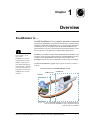
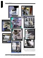
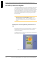


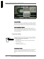


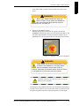


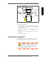
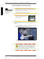
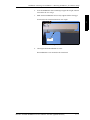
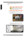
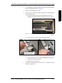
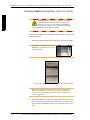

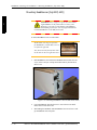
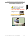
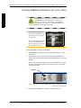
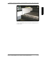

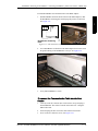
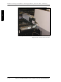
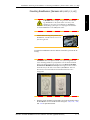

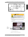
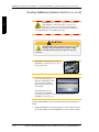


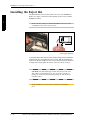

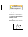
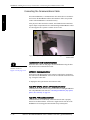
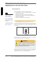
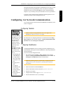
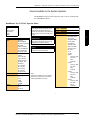
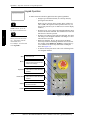

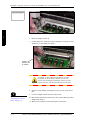
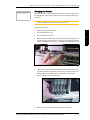

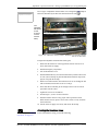

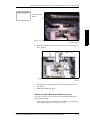
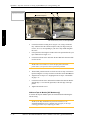
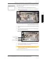

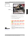


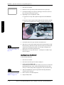


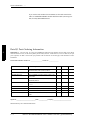
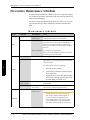
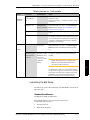

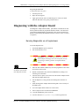
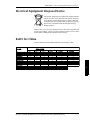


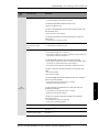
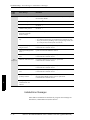

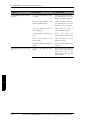


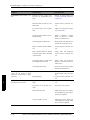

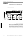
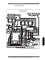


![Manual condicionador de sinal SD20 [PTBR]](http://vs1.manualzilla.com/store/data/006085115_1-891da68fb4d8bbd4bc5f0d8350060514-150x150.png)