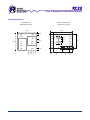
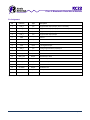
1
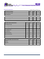
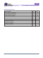
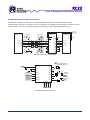
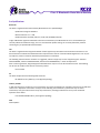
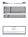
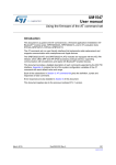
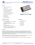
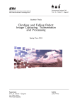
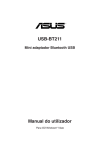
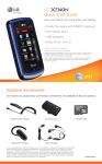
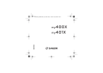
KC22 Class 2 Bluetooth Data Micro Module Firmware Features Wireless Data Communications Subsystem Embedded Bluetooth Serial Port Profile (SPP) Easy To Use AT Command Interface Using UART OEM Programmable Configuration Remote Command And Control Multipoint / Piconet Capable Custom Firmware Available Hardware Features 13.4mm x 11.3mm Applications CSR BlueCore 4 Ext Chipset Bluetooth Serial Cable Replacement Bluetooth v2.1 + EDR Bluetooth Data Cable Replacement 2.4GHz Class 2 Radio Bluetooth Advertising Range Typically Exceeds 20m Bluetooth RFID Tag Readers High Speed Data Rate Up To 3Mbps Bluetooth Digital Cameras 4 Digital Programmable I/O Pins Bluetooth Digital Picture Frames 1 Analog Programmable I/O Pins Bluetooth Hand‐Held Bar Code Readers UART & SPI Interfaces Bluetooth Medical Monitoring External Antenna Port Bluetooth Credit Card Readers 8Mbit Flash Memory Many, many, more . . . Description The KC22 data modules are pre‐engineered, pre‐qualified, and highly tuned surface mount PCB modules that provide fully embedded, ready to use Bluetooth wireless technology. Multi‐surface pads provide both bottom pads for high volume reflow soldering and edge pads for low volume hand soldering. The KC22 offers reprogrammable, embedded firmware for serial cable replacement deploying the Bluetooth Serial Port Profile (SPP). OEM specific parameters and settings can be easily loaded into these modules. Our kcSerial embedded firmware provides an easy to use AT style command interface over UART. kcSerial is capable of storing OEM default settings, and is upgradable over UART. kcSerial also provides remote control capability, where our AT commands can be issued remotely from any other Bluetooth device using SPP. Custom firmware is available. (For Audio applications, Radio Datacom recommends our KC5290 ‐ Class 2 Bluetooth Audio Module) © 2009 Radio Datacom www.radiodatacom.com Page 1 of 13 KC22 Class 2 Bluetooth Data Micro Module Standard Bluetooth Data Profiles The Radio Datacom KC22 data modules comes standard with kcSerial which includes support for (DUN) Dial‐up Networking Profile, and (SPP) Serial Port Profile. DUN ‐ Dial‐up Networking Profile DUN provides a standard to access the Internet and other dial‐up services over Bluetooth technology. The most common scenario is accessing the Internet from a laptop by using your mobile phone as a wireless dial‐up modem. SPP ‐ Serial Port Profile The SPP is a very popular widely used profile for transmitting data in place of a serial cable. SPP defines how to set up virtual serial ports and connect two Bluetooth enabled devices. A scenario would be using two devices, such as PCs or laptops, as virtual serial ports and then connecting the two devices via Bluetooth technology. Available Bluetooth Data Profiles KC22 is capable of supporting each of these standard profiles. Contact Radio Datacom for customization options. AVRCP ‐ Audio Video Remote Control Profile AVRCP is designed to provide a standard interface to control TVs, hi‐fi equipment, or others to allow a single remote control (or other device) to control all the A/V equipment to which a user has access. It may be used in concert with A2DP or VDP. BIP ‐ Basic Imaging Profile BIP defines how an imaging device can be remotely controlled, how an imaging device may print, as well as how an imaging device can transfer images to a storage device. BIP also includes the ability to resize and convert images to make them suitable for the receiving device. BPP ‐ Basic Printing Profile BPP allows devices to send text, emails, vCards, images or other items to printers based on print jobs. Prints emails, images, vCard, vCalendar, text messages and plain or formatted text from devices like a mobile phone or PDA to a printer. CTP ‐ Cordless Telephone Profile Used for either a dedicated cordless phone or a mobile phone that acts as a cordless phone when in proximity to a base station implementing the CTP. FTP ‐ File Transfer Profile FTP defines how folders and files on a server device can be browsed by a client device. Once a file or location is found by the client, a file can be pulled from the server to the client, or pushed from the client to the server using GOEP. A typical scenario would be transferring files wirelessly between two PCs or laptops, or browsing and retrieving files on a server. © 2009 Radio Datacom www.radiodatacom.com Page 2 of 13 KC22 Class 2 Bluetooth Data Micro Module GAVDP ‐ General Audio/Video Distribution Profile GAVDP provides the basis for A2DP and VDP, the basis of the systems designed for distributing video and audio streams using Bluetooth technology. A typical scenario is a set of wireless stereo headphones and a music player, such as an MP3 player or Walkman. The music player sends messages to the headphones to establish a connection or adjust the stream of music, or visa versa. GEOP ‐ Generic Object Exchange Profile GOEP is used to transfer an object from one device to another. A simple scenario would be using Bluetooth technology to send information like files, vCards, vCalendars and images between your mobile phone or PDA and a PC. HID ‐ Human Interface Device Profile The HID profile defines the protocols, procedures and features to be used by Bluetooth HID such as keyboards, pointing devices, gaming devices and remote monitoring devices. The most common usage would be your wireless desktop, keyboard, mouse, etc. OPP – Object Push Profile OPP defines the roles of push server and push client. These roles are analogous to and must interoperate with the server and client device roles that GOEP defines. An example scenario would be the exchange of a contact or appointment between two mobile phones, or a mobile phone and a PC. PAN – Personal Area Networking Profile PAN describes how two or more Bluetooth enabled devices can form an ad‐hoc network and how the same mechanism can be used to access a remote network through a network access point. SDAP ‐ Service Discovery Application Profile SDAP describes how an application should use SDP to discover services on a remote device. It illustrates several approaches to managing the device discovery via Inquiry and Inquiry Scan and service discovery via SDP. The ideas contained in the SDAP specification augment the basic specifications provided in GAP, SDP, and the basic processes of device discovery. The use cases for SDAP are intended to encompass the majority of service discovery scenarios associated with all profiles and devices. SYNC ‐ Synchronization Profile The SYNC profile is used in conjunction with GOEP to enable synchronization of calendar and address information (personal information manager [PIM] items) between Bluetooth enabled devices. VDP ‐ Video Distribution Profile VDP defines how a Bluetooth enabled device streams video over Bluetooth wireless technology. Sample use cases include the streaming of a stored video from a PC media center to a portable player or streaming from a digital video camera to a TV. © 2009 Radio Datacom www.radiodatacom.com Page 3 of 13 KC22 Class 2 Bluetooth Data Micro Module Physical Dimensions KC22 Top View (dimensions in mm) KC22 Landing Pattern (dimensions in mm) 15.29 13.41 PIO 1 2 14 TXD PIO 0 1 © 2009 Radio Datacom 9.76 0.76 1.65 1.55 1.14 www.radiodatacom.com 1.04 13 RXD 1.50 1.30 0.25 0.37 1.65 PIO 4 3 0.76 0.74 0.23 12 RTS 0.94 0.71 4.85 PIO 5 4 SPI CLK 11 CTS SPI CSB ANT 6 GND 5 SPI MISO AIO 0 10 RSET 1.14 6.77 9 GND 7 1.65 VDD SPI MOSI 11.28 8 Page 4 of 13 KC22 Class 2 Bluetooth Data Micro Module Pin Assignment Pin Function Type Description 1 PIO_0 I/O Programmable Input/Output [Class 1 Rx Enable] 2 PIO_1 I/O Programmable Input/Output [Class 1 Tx Enable] 3 PIO_4 I/O Programmable Input/Output 4 PIO_5 I/O Programmable Input/Output 5 GND ‐ 6 ANT Output 7 GND ‐ 8 VDD Input 9 AIO_0 I/O 10 RSET Input Hardware Reset 11 UART_CTS Input UART Clear To Send 12 UART_RTS Output UART Ready to Send 13 UART_RXD Input 14 UART_TXD Output TP SPI MISO Input TP SPI MOSI Output SPI Master Out TP SPI CS Input SPI Chip Select TP SPI CLK Input SPI Clock Ground External Antenna Port Ground 3.3V Regulated Input Analog Programmable Input/Output UART Data Input UART Data Output SPI Master In [Special/optional pin features shown in brackets] © 2009 Radio Datacom www.radiodatacom.com Page 5 of 13 KC22 Class 2 Bluetooth Data Micro Module Electrical Characteristics (Conditions VDD= 3.3V and 25 °C) Absolute Maximum Ratings Min Max Unit Storage temperature range ‐40 150 °C Supply voltage VDD ‐0.4 3.7 Volts Recommended Operating Conditions Min Max Unit Temperature Range ‐40 85 °C Supply Voltage VDD (3.3V Recommended) 3.1 3.6 Volts Digital PIO & UART Pins Characteristics Min Typ Max Unit Input Voltage Low Logic ‐0.4 ‐ 0.8 Volts Input Voltage High Logic 2.3 ‐ 3.7 Volts Output Voltage Low Logic ‐ ‐ 0.2 Volts Output Voltage High Logic 3.1 ‐ ‐ Volts Input Leakage Current ‐1 ‐ +1 µA Input Capacitance 1.0 ‐ 5.0 pF Weak Internal Pull‐Up ‐5.0 ‐1.0 ‐0.2 µA Weak Internal Pull‐Down +0.2 +1.0 +5.0 µA Strong Internal Pull‐Up ‐100 ‐40 ‐10 µA Strong Internal Pull‐Down +10 +40 +100 µA Min Max Unit Resolution 8 Bits Sample Rate 50 Per Sec Voltage 0 1.8 V Analog Programmable I/O Pins Characteristics © 2009 Radio Datacom www.radiodatacom.com Page 6 of 13 KC22 Class 2 Bluetooth Data Micro Module Electrical Characteristics Cont. Current Consumption Avg Unit ACL Data 115Kbps Data Transfer(Master) 11 mA ACL Data 115Kbps Data Transfer(Slave) 25 mA Connection, No Data Traffic (Master) 4.6 mA Connection, No Data Traffic (Slave) 17 mA Peak current 90 mA Sniff Mode (40ms sniff) (Master) 2.4 mA Sniff Mode (40ms sniff) (Slave) 2.1 mA Sniff Mode (1.3s sniff) (Master) 0.4 mA Sniff Mode (1.3s sniff) (Slave) 0.4 mA Deep Sleep 40 µA © 2009 Radio Datacom www.radiodatacom.com Page 7 of 13 KC22 Class 2 Bluetooth Data Micro Module Firmware Interface The KC22 offers our powerful kcSerial firmware interface using the UART, which provides an easy to use AT style text command interface. The firmware interface allows persistent storage of configuration parameters such as device name, default baud rate, security PIN, and automatic connection settings. Additionally kcSerial provides operational commands such as discovery, connections, security, read/write commands for I/O pins, and our remote command mode offering this same programming interface on the linked remote device as well. The kcSerial 2.4 firmware is compatible with kcSerial 2.2 firmware used on previous versions of KC22 modules. Several new commands are available, offering greater control over features and settings. Please refer to our kcSerial User Guide for additional information. kcSerial v2.4 AT Command List Operation Commands Configuration Commands AT+KC Bond AT+KC AllowBonding AT+KC IndicatorActivity AT+KC Bypass AT+KC Build AT+KC IndicatorCPU AT+KC DisableBond AT+KC ChangeBaud AT+KC IndicatorConnection AT+KC Discovery AT+KC ChangeDefaultBaud AT+KC LocalName AT+KC DunConnect AT+KC COD AT+KC SaveSettings AT+KC DunDisconnect AT+KC DeepSleep AT+KC Security AT+KC ExitSniff AT+KC DeepSleepBlocking AT+KC ShowSettings AT+KC GPIOConfig AT+KC DefaultLocalName AT+KC SmartCableSetup AT+KC GPIORead AT+KC DefaultPinCode AT+KC SmartCableReset AT+KC GPIOWrite AT+KC DeleteSmartCable AT+KC UpdateInquiryScan AT+KC HCImode AT+KC DisableBond AT+KC UpdatePageScan AT+KC RemoteCommand AT+KC DisconnectNotice AT+KC Verbose AT+KC RemoteCmdDisconnect AT+KC EnableBond AT+KC Version AT+KC Reset AT+KC EraseBondTable AT+KC Sniff AT+KC FactoryReset AT+KC SPPConnect AT+KC Help AT+KC SPPDisconnect AT+KC HostEvent © 2009 Radio Datacom www.radiodatacom.com Page 8 of 13 KC22 Class 2 Bluetooth Data Micro Module Hardware Interfaces SPI Interface The SPI pins are available for firmware loading and supported by the CSR Software Development Kit. UART Interface The UART is compatible with the 16450 industry standard. Four signals are provided with the UART interface. The TXD and RXD pins are used for data while the CTS and RTS pins are used for flow control. The UART pins operate at TTL voltage level and must be translated to higher RS‐232 voltage levels for communicating with PC hosts. A Maxim 3225 series or similar translator is recommend. It is highly recommended that UART pins are available for external connection (DB‐9 connector or test points) to allow firmware reinstallation or updates. Firmware Command and Control KC22 modules can be connected to PC or MCU hosts using the UART interface. The kcSerial firmware on the KC22 module provides an easy to use AT style command interface using simple text commands and parameters. Please refer to our kcSerial User Guide for additional information. PIO Interface Pins PIO pins are read and write enabled via kcSerial commands. Inputs can be configured for weak pull‐up, weak pull‐down, strong pull‐up, strong pull‐down. Voltage input tolerance and output level is directly related to the VDD level. AIO Interface Pins AIO_0 can be enabled for analog input or output, providing 8 bit samples at rates up to 50 samples/sec. Analog pins are 1.8V logic for input mode, and 3.3V logic for output mode. AIO pins can be configured for output mode, sending clock signals of 8, 16, 24, or 48 MHz. AIO pin usage must be custom programmed by Radio Datacom for desired operation. Antenna Port The KC22 module already contains a balun‐filter onboard, so the antenna port only requires a standard 2.4 GHz RF transmission line with a 50 ohm load. Design the antenna circuit according to the antenna manufacturer guidelines. Some designs may only need the chip antenna itself. A few recommended chip antennas: Johanson 2450AT18B100E, Johanson 2450AT43A100E, or Antenova Rufa A5839. For PCB transmission line design, we recommend the following online calculator: http://www.emclabinfo.com/emc_calc/microstrip.htm © 2009 Radio Datacom www.radiodatacom.com Page 9 of 13 KC22 Class 2 Bluetooth Data Micro Module Application Notes Highly recommend test points for all four SPI pins, for emergency factory debugging and firmware loading. UART 5‐wire serial (TXD, RXD, CTS, RTS, GND). RS232 hardware flow control is enabled in firmware by default. Recommend connections to all four UART pins for RS232 connections or at least test points for firmware upgrades. UART optional 3‐wire serial (TXD, RXD, GND). Pull up CTS pin to override hardware flow control setting. UART interfaces are 3V3 TTL. A voltage level shifter is required when interfacing to PC standard RS232 ports. Power supply to module should have less than 10mVrms noise between 0‐10MHz, and spikes should be minimal. Regulator should have a fast response time < 20µs. It is essential that the power rail recover quickly. 10µF or larger capacitor filter for VDD input. All unused pins should be unconnected. The area around the antenna should be free of any ground planes, power planes, trace routings, wire harnesses or metal. Minimum clearance is 5mm, but additional clearance allows improved range and throughput. Do not clean modules with Alcohol which can interact with no‐clean solder flux residue. Do not use ultra sonic cleaning, which may cause internal interconnect damage. We recommend providing our preferred factory programming interface for all devices: 2.54 MM HEADER PROGRAM INTERFACE 8 SPI CLK SPI MOSI SPI MISO SPI CSB GND USB DP USB DM 3V3 1 © 2009 Radio Datacom www.radiodatacom.com Page 10 of 13 KC22 Class 2 Bluetooth Data Micro Module Example Hardware Interface Connections Radio Datacom modules provide UART, SPI, and PIO hardware interfaces. This section illustrates a typical implementation, and does not consider all cases. Our engineers are available to review designs and answer any other design questions. Contact our engineering department directly by email: [email protected] 3.3V COMPUTER / MICROPROCESSOR 1 DB-9 MALE DTE 6 2 UART_RXD 7 UART_RTS 3 UART_TXD 8 UART_CTS 4 MAX3225 LEVEL SHIFTER DB-9 FEMALE DCE 1 6 RXD TXD RTS CTS TXD RXD CTS RTS 9 2 VDD INVALID GND 3 8 T1 IN UART_TXD UART_CTS R2 IN R2 OUT UART_RXD C1+ 0.1UF 5 0.1UF GND R1 OUT T2 OUT 4 3V3 10UF R1 IN T1 OUT 7 9 5 FORCE OFF BLUETOOTH DATA MODULE UART_RTS T2 IN V+ C1- V- C2+ GND C2- READY 10UF 0.1UF 0.1UF UART connection with level shifting GND 5 UART CTS 11 UART CTS PIO 5 4 UART RTS 12 UART RTS PIO 4 3 UART RXD 13 UART RXD PIO 1 2 UART TXD 14 UART TXD PIO 0 1 NMOS 430 10 RSET L EXAMPLE OUTPUT LED 3.3V 10K EXAMPLE INPUT BUTTON 3.3V SPI CLK ANT 6 SPI CSB GND 7 9 AIO 0 SPI MISO 8 VDD 10μF SPI MOSI 3.3V DESIGN ANTENNA CIRCUIT TO MANUFACTURER SPEC TEST POINTS Example KC22 module schematic © 2009 Radio Datacom www.radiodatacom.com Page 11 of 13 KC22 Class 2 Bluetooth Data Micro Module Pre Qualifications Bluetooth The KC22 is registered with and licensed by Bluetooth SIG as a qualified design. Qualification Design ID: B015017 Bluetooth Version: 2.1 + EDR Qualified Profiles: BB, DUN, GAP, HCI, L2CAP, LM, RFCOMM, SDP, SPP Usage of Bluetooth registered trademarks must be licensed directly from Bluetooth SIG. A no cost membership is currently offered for trademark usage, and a no cost Bluetooth product listings are currently offered for products containing our pre‐qualified Bluetooth modules. FCC The KC22 is registered with and granted limited modular approval by the Federal Communications Commission. The KC22 meets the conducted and radiated emission requirements of the FCC "Code of Federal Regulations" Title 47, Part 15, Subpart C, Section 15.247 for Bluetooth spread spectrum transmitters. The following external antenna solutions are suggested, and will comply with our FCC equipment grant: Johanson 2450AT18B100E, Johanson 2450AT43A100E, Antenova Rufa 3030A5839‐01, ¼ wave monopole wire. With a written agreement, Original Equipment Manufacturers may use our FCC ID transmitter license. The following FCC ID must be visible on the exterior of final the product. FCC ID: S2242 CE The KC22 complies with the following EMC Directives: EN 300.328 V1.6.1 (2004‐11) [Final approval pending] Industry Canada IC Warning Statement: The device’s user manual does not contain the following or equivalent statement as per RSS‐GEN section 7.1.5: Operation of this device is subject to the following two conditions: (1) this device may not cause interference, and (2) this device must accept any interference, including interference that may cause undesired operation of the device. IC ID: 8193A‐BTMODULECL2 [Final approval pending] SAR SAR compliant. © 2009 Radio Datacom www.radiodatacom.com Page 12 of 13 KC22 Class 2 Bluetooth Data Micro Module Ordering Information Product Series KC22 Product Version 6.0 Country of Manufacture USA Order Part Number Description KC22 Class 2 Bluetooth Data Micro Module w/ kcSerial Standard Firmware KC22‐FW Class 2 Bluetooth Data Micro Module w/ Custom Firmware Datasheet Version Version Changes Dec 15, 2009 Original release Radio Datacom LLC 9601 N 16th Street Phoenix, Arizona 85028 (602) 235‐0350 Phone www.radiodatacom.com [email protected] ‐‐‐ While every care has been taken to ensure the accuracy of the contents of this document, Radio Datacom cannot accept responsibility for any errors. Radio Datacom reserves the right to make technical changes to its products as part of its continuous development program. Radio Datacom’s products are not authorized for use in life‐support or safety‐critical applications. © 2009 Radio Datacom www.radiodatacom.com Page 13 of 13