1
Click here for link
to Contents
HD – T
BODY
INSTALLATION
MANUAL
GKB 4x2 Series
CWB 6x4 Series
GWB 6x4 Series
Issued Date: May 2010
Please ensure you have the latest revision of this manual by checking the
UD Trucks website: www.udtrucks.com.au
FOREWORD
This body installation manual presents the basic data and describes precautions involved in
designing and manufacturing the body and general equipment to be installed on the UD
Trucks forward control 4x2 GKB-Tractor series, 6x4 CWB series and 6x4 GWB-Tractor series
of heavy-duty trucks.
The body manufacturer is requested to install a quality vehicle body which satisfies the
customer’s requirements by observing the precautions outlined in this manual.
It is the responsibility of the body manufacturer or the modification company, to make sure
that the completed vehicle, with body and equipment, or after modification, confirms to all
applicable laws and regulations of the State or Territory in which the vehicle is to be
registered.
IMPORTANT NOTICE
•
•
•
The information contained herein is based on the latest product information at the time of
publication.
The information described in this manual is general and nothing contained herein is to be
regarded as authorisation by UD Trucks of the assembly or modification of any particular
vehicle.
UD Trucks is constantly working to improve its products and reserves the right to make
changes in design, materials, equipment, information, specifications and models and to
discontinue models or equipment at any time without prior notice.
UD Trucks
120 Hume Highway
CHULLORA NSW 2190
© Volvo Group Australia Pty Ltd ABN 27 000 761 259
AdBlue is a registered trademark of the Verband der Automobilindustrie e.V. (VDA)
LIST OF ABBREVIATIONS USED IN THIS MANUAL
ABS
ADR
AMT
AS
AS/NZS
ATM
AVSR
CML
DITRDLG
EBS
ECAS
EHS
Ft
GCM
GVM
LRG
MSDS
PCV
PTO
RHS
ROF
Rr
SSM
SSMM
UDT
UDTC
VIN
VSB
Anti-Lock Braking System
Australian Design Rules
Automated Manual Transmission
Australian Standard
Australian Standard/New Zealand Standard
Aggregate Trailer Mass
Australian Vehicle Standards Rules 1999
Concessional Mass Limits
Department of Infrastructure, Transport, Regional Development and Local
Government (formerly DoTaRS)
Electronic Braking System
Electronically Controlled Air Suspension
Easy Hill Start
Front
Gross Combination Mass
Gross Vehicle Mass
Load Restraint Guide
Material Safety Data Sheet
Partially Completed Vehicle
Power Take Off
Rolled Hollow Section
Rear of Frame
Rear
Second-Stage-of-Manufacture
Second-Stage-of-Manufacture, Manufacturer
UD Trucks - Australia
UD Trucks Corporation - Japan
Vehicle Identification Number (refer to Owner’s Manual for location on the
vehicle)
Vehicle Standards Bulletin
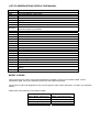
MODEL CODING
This manual uses the UDTC model code designations as appear on the trucks compliance plate, vehicle
identification plate, VIN (4~8th characters) and in the UDTC Service Manuals.
These UDTC model code designations vary from the general “sales model” description, as used in the Australian
market.
Please refer to the following cross reference table.
Australian Market:
“Sales Model” Description
GK400
GW400
GW400 Long
GW470
UDTC:
Model Code Designation
GKB4D
GWB4D
CWB4D
GWB4D
CONTENTS
FOREWORD
LIST OF ABBREVIATIONS USED IN THIS MANUAL
MODEL CODING
VEHICLE SPECIFICATIONS
•
•
•
GKB4D 4x2 Tractor
CWB4D 6x4 Rigid
GWB4D 6x4 Tractor
GUIDELINES – LEGISLATION
GENERAL OVERVIEW
AUSTRALIAN DESIGN RULES (ADR) CERTIFICATION
• Vehicle Manufacturer
• Second-Stage-of-Manufacture
• Vehicle Standards Bulletin No. 6
MANUFACTURER’S GUIDELINES
OTHER LEGISLATION
• Australian Vehicle Standards Rules 1999
• Load Restraint Guide
• Concessional Mass Limits
• State/Territory Registration Authorities
ADR SUMMARY – Applicable to ’08 M/Y
SSM AND BODY BUILDERS ADR CHECK LIST
• Positioning of Lamps and Reflectors: Supplied by UDT
• Items Supplied at SSM
GUIDELINES – BODY INSTALLATION
SUB-FRAME AND BODY INSTALLATION
1. Sub-Frame Shape and Mounting
2. Front End Shape
3. Positions of Front-End Reinforcement
4. Mounting Brackets
5. Location Plates
6. Combination with Chassis Frame
(1) “U-Bolt” Mounting
(2) Preventing Fore-and-Aft Movement
(3) Sub-Frame Connecting Devices - Location
7. Long Wheelbase Truck
CHASSIS FRAME
1. Drilling the Frame
2. Riveting
MECHANICAL CONNECTIONS BETWEEN VEHICLES
1. Towbars, Tow Couplings and Fifth Wheels
LIFTING DEVICES
1. Cranes
2. Tailgate/Platform Loader
PRECAUTIONS DURING ELECTRIC WELDING
PRECAUTIONS ON VEHICLES EQUIPPED WITH: •
•
•
•
ABS
EBS
ESCOT
AutoShift
• EHS
RELOCATION OF BATTERY OR RELAY BOX
PRECAUTIONS FOR BODY INSTALLATION AROUND THE AdBlue® TANK
REMODELING THE EXHAUST SYSTEM
OTHER
TIGHTENING TORQUE OF GENERAL CHASSIS BOLTS
-1-
Issued Date: May 2010
CONTENTS
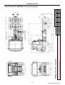
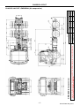
CHASSIS LAYOUT
•
• GKB4DAD (A = Air Suspension)
• CWB4DAW
• GWB4DAH
GWB4DLH (L = Trunnion Suspension)
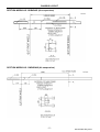
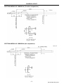
SECTION MODULUS
•
• GKB4DAD (A = Air Suspension)
• CWB4DAW
• GWB4DAH
GWB4DLH (L = Trunnion Suspension)
ALLOWANCE FOR REAR AXLE, SUSPENSION & TYRE ARTICULATION
1. Allowance for Tyre Movement
2. Allowance for Rear Axle Movement
1) Trunnion Suspension (GWB4DL)
2) Air Suspension – Full Floating Type (GKB4DA and CWB4DA)
3) Air Suspension – Semi Floating Type (GWB4DA)
ALLOWANCE FOR BODY CLEARANCE, CAB TILT & SUSPENSION MOVEMENT
PTO
REAR ENGINE PTO
TRANSMISSION PTO
• GKB4D Factory Option with APR90A Transmission
• CWB4D, GWB4D with EATON FULLER Transmission
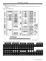
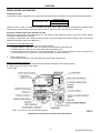
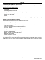
ENGINE CONTROL SYSTEM
• Explanation of Functions of Engine Control Parts and Installation
a. Junction Connectors
Connection Pattern – STANDARD CHASSIS-CAB
End of Line Programming (EOLP) Parameters
Connection Pattern – When ENGINE PTO is Installed
Connection Pattern – When TRANSMISSION PTO is Installed
Optional Engine Control Parts Installed during UDTC Production
b. External Engine Control Lever Unit
c. PTO and Governor Switch
d. Parts to be Prepared when the External Control Lever is Retrofitted
ELECTRICAL SYSTEM
HARNESS FOR REAR LAMPS
• Wiring and Installation of Rear Combination and Registration Plate Lamps
• Position of Rear Combination, Reversing and Registration Plate Lamps
• Connection to Spare Circuits in Chassis Harness LH
LOCATION OF FUSE BOX, RELAY AND OTHER UNITS IN THE CAB
USING THE ADDITIONAL POWER SOURCES
1. Additional Power Source Directly Connected to the Battery
2. Additional Power Source in the Cab
3. Using Power from Additional Power Sources
GENERAL PRECAUTIONS ON ELECTRICAL WIRING
CAB
• Allowance for Cab Tilt and Suspension Movement
• Installation of Equipment/Attachments around the Cab
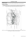
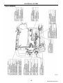
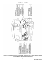
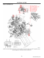
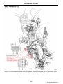
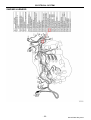
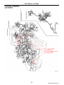
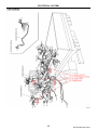
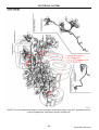
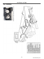
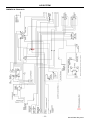
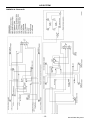
HARNESS LAYOUT
• Cab Harness
• Main Harness (cab interior) RH
• Main Harness (cab interior) LH
• Engine Harness
• Chassis Harness
• Tail Harness
• AutoShift
-2-
Issued Date: May 2010
CONTENTS
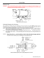
AIR SYSTEM
• Discharge of Air
• Preferential Charging of the Air System
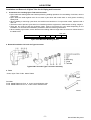
• Installation and Removal of Nylon Tube for Air Piping and Connector
AIR PIPING DIAGRAMS
• GKB4DA
• CWB4DA
• GWB4DL/A
PAINTING
PRECAUTIONS ON PAINTING
• Painting of Cabs
• Positions of Black-Colour Film attached on Cabs
• Parts that should be Removed before Painting
• Masking of Parts that Must not be Painted
• Precautions on Painting the Air Spring for Cab Air Suspension
• Precautions on Painting Resin (plastic) Parts
• Attachment of Decals
ALLOWABLE TEMPERATURE LIMITS OF MAJOR PARTS
BOUNDARIES OF CAB PAINTING
PRECAUTIONS ON PAINTING THE DISC WHEEL
APPENDIX
•
•
•
RHS of Chassis Air Tank Relocation – GWB4D: To Install Spare Wheel/Tyre Assembly
ROF Air Tank Relocation – GWB4D: Air Rear Suspension Models for Tipper Application
Rear Chassis Dock – GWB4DA: Prime Mover Application
-3-
Issued Date: May 2010
CONTENTS
-4-
Issued Date: May 2010
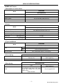
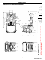
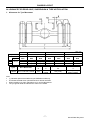
VEHICLE SPECIFICATIONS
GKB4D 4x2 Tractor
1) Description of Vehicle Series
GKB4DADH
Model
(Air suspension)
Wheelbase
(mm)
3530
Engine
GE13TB
Brake System
Full Air with ABS, EBS and EHS
Transmission
APR90A with ESCOT control
2) Frame
GKB4DADH
Model
(Air suspension)
Height x Flange Width x Thickness
(mm)
Main 275 x 90 x 7
Inner Reinforcement 261 x 82 x 3.2
Side Rail Assembly Width
(mm)
840
Tensile Strength
(MPa {kgf/mm²})
539 {55}
Yield Point
(MPa {kgf/mm²})
471 {48}
Section Modulus - Max.
(x 105mm³)
9.92
3) Tyres and Wheels
GKB4DADH
Model
(Air suspension)
Tyre
Rim and wheel
STD
295/80R22.5 (Front/Spare), 11R22.5-16PR (Rear)
OPT
11R22.5-16PR (All Positions)
22.5 x 8.25 offset 165mm, 10 stud (ISO)
4) Front Spring
STD
SPECIFICATIONS
Length x Width x Thickness – No. of
Springs (mm)
Spring Constant
(N/mm {kgf/mm})
1800 x 90 x 22-1, 24-2, 14-1
292 {29.8}
5) Rear Spring
STD
SPECIFICATIONS
Type
Spring Constant
(N/mm {kgf/mm})
Four bag per axle, full floating NDMC
air suspension with upper V link, lower
torque rods, stabiliser bar and ECAS
height control.
RFCN: RF2058
125 {12.8} @ 500 kPa
-1-
Issued Date: May 2010
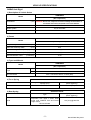
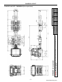
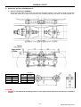
VEHICLE SPECIFICATIONS
CWB4D 6x4 Rigid
1) Description of Vehicle Series
CWB4DAW
Model
(Air suspension)
6500
Wheelbase
(mm)
CAUTION: Due to rear suspension torsional loadings the wheelbase of
this model must not be shortened to less than 5500mm.
Engine
GE13TB
Brake System
Full Air with ABS
Transmission
RTLO14913A
2) Frame
CWB4DAW
Model
(Air suspension)
Height x Flange Width x Thickness
(mm)
298 x 90 x 7
Side Rail Assembly Width
(mm)
840
Tensile Strength
(MPa {kgf/mm²})
539 {55}
Yield Point
(MPa {kgf/mm²})
471 {48}
Section Modulus - Max.
(x 105mm³)
12.19
3) Tyres and Wheels
CWB4DAW
Model
(Air suspension)
Tyre
Rim and wheel
STD
11R22.5-16PR
OPT
275/70R22.5
22.5 x 8.25 offset 165mm, 10 stud (ISO)
4) Front Spring
Vehicle Model
STD
SPECIFICATIONS
Length x Width x Thickness – No. of
Springs (mm)
Spring Constant
(N/mm {kgf/mm})
1550 x 90 x 20-1, 22-2, 14-1
369 {37.6}
5) Rear Spring
STD
SPECIFICATIONS
Type
Spring Constant
(N/mm {kgf/mm})
Four bag per axle, full floating NDMC air
suspension with upper V links, lower
torque rods, stabiliser bars and ECAS
height control.
RFCN: RF2058
125 {12.8} @ 600 kPa
-2-
Issued Date: May 2010
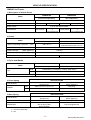
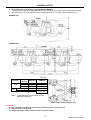
VEHICLE SPECIFICATIONS
GWB4D 6x4 Tractor
1) Description of Vehicle Series
Model
Wheelbase
GWB4DLHH
GWB4DAHH
(Trunnion suspension)
(Air suspension)
(mm)
Engine
3950
GE13TB
GE13TD
Brake System
GE13TB
GE13TD
Full Air with ABS and EBS
Transmission
RTLO18918B
or
RTLO18918A-AS3
RTLO14913A
RTLO14913A
RTLO18918B
or
RTLO18918A-AS3
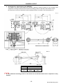
2) Frame
Model
Height x Flange Width x Thickness
(mm)
Side Rail Assembly Width
(mm)
GWB4DLHH
GWB4DAHH
(Trunnion suspension)
(Air suspension)
Main 298 x 90 x 7
298 x 90 x 7
Inner Reinforcement 284 x 75 x 4.5
840
Tensile Strength
(MPa {kgf/mm²})
539 {55}
Yield Point
(MPa {kgf/mm²})
471 {48}
Section Modulus - Max.
(x 105mm³)
18.59
14.75
GWB4DLHH
GWB4DAHH
(Trunnion suspension)
(Air suspension)
3) Tyres and Wheels
Model
Tyre
Rim and wheel
STD
295/80R22.5 (Front/Spare), 11R22.5-16PR (Rear)
OPT
11R22.5-16PR (All Positions)
22.5 x 8.25 offset 165mm, 10 stud (ISO)
4) Front Spring
SPECIFICATIONS
Length x Width x Thickness – No. of
Springs (mm)
Spring Constant
(N/mm {kgf/mm})
STD
1550 x 90 x 21-1, 23-2, 19-1
429 {43.8}
OPT
1550 x 90 x 22-1, 23-2
364 {37.1}
Vehicle Model
GWB4D
5) Rear Spring
Vehicle Model
GWB4DLHH
SPECIFICATIONS
Length x Width x Thickness – No. of
Springs (mm)
Spring Constant
(N/mm {kgf/mm})
1300 x 90 x 20-2, 22-3, 20-3
2672 {272.5}
HAS 460 air suspension
GWB4DAHH
with air dump valve
RFCN: RF2022
Note: The 6th character of the vehicle model code denotes the rear suspension type;
L = Trunnion (steel leaf)
A = Air
-3-
125 {12.8} @ 600 kPa
Issued Date: May 2010
VEHICLE SPECIFICATIONS
-4-
Issued Date: May 2010
GUIDELINES - LEGISLATION
GENERAL OVERVIEW
This manual has been prepared to provide intermediate and final stage manufacturers with basic data, such as
specifications and dimensions, of the chassis-cab manufactured by UD Trucks Corporation (“UDTC”). This manual
is not intended to provide instructions or authorisation by UDTC for modification, alteration or completion of any
vehicle and nothing contained herein is to be regarded as providing any such instructions or authorisation. UDTC
and UD Trucks - Australia (“UDT”) shall not be responsible for any modification, alteration or completion of the
vehicle which shall be the responsibility of subsequent Second-Stage-of-Manufacture (“SSM”) manufacturers
(“SSMM”).
The chassis-cab manufactured by UDTC, and supplied by UDT, is designed to comply with all applicable Australian
Design Rules (“ADR”) for a Partially Competed Vehicle (“PCV”) at the time of manufacture. ADR compliance of the
chassis-cab manufactured by UDTC is granted by the Department of Infrastructure, Transport, Regional
Development and Local Government (“DITRDLG”). Proof of compliance of an individual PCV is shown by UDT’s
fitment of an ADR Compliance Plate.
Various regulations relating to vehicle performance, equipment, and safety have been issued by government
organisations. These regulations include, but are not limited to the DITRDLG regulations. Other Federal, State,
Territory and local regulations may also apply. SSMM, body builders and motor carriers are responsible for
knowing and complying with all regulations that may apply to the vehicle. A finished vehicle may also require
devices that are not specified in the regulations. SSMM, body builders and motor carriers must determine what
safety devices are necessary for the safe operation of the vehicle. Nothing in this manual should be taken as a
representation that all equipment necessary for the safe operation of the vehicle in its intended use has been
installed on the partially completed chassis-cab.
All illustrations and specifications in this Body Installation Manual are based on the latest information and believed
to be correct at the time of publication. The numerical values used herein are for standard specifications and
dimensions. Occasionally, vehicle assembly tolerances may produce some variance in the actual vehicle.
UDTC and UDT reserve the right to make changes in design, materials, equipment, information, specifications and
models and to discontinue models or equipment at any time without notice and without incurring any obligation.
Additional copies of the latest revision of this manual may be obtained from the UDT website:
www.udtrucks.com.au
-1-
Issued Date: May 2010
GUIDELINES - LEGISLATION
AUSTRALIAN DESIGN RULES (ADR) CERTIFICATION
VEHICLE MANUFACTURER
In accordance with the Motor Vehicle Standards Act 1989, it is the responsibility of UDTC to ensure vehicles
supplied by UDT in chassis-cab (i.e. PCV) configuration conform to the conditions specified in the Compliance
Plate Approvals issued by the DITRDLG.
ADR Circular 0-4-11, Certification of Chassis-Cab Vehicles, clause 4.1 permits the vehicle manufacturer to supply
a PCV in the nature of a chassis-cab that may not fully comply with certain ADR’s, as follows.
4.1.1 The “Position” requirements of ADR 13/00 for the following Lighting and Light Signalling devices:• Reversing Lamp (ADR 1/00) – as per ADR 13/00 Appendix A clause 6.4.4
• Rear Direction Indicators (ADR 6/00) – as per ADR 13/00 Appendix A clause 6.5.4
• Rear Reflex Reflectors (ADR 47/00) – as per ADR 13/00 Appendix A clause 6.14.4
• Devices for Illumination of Rear Registration Plates (ADR 48/00) – as per ADR 13/00 Appendix A clause
6.8.4
• Rear Position (Side Lamps) (ADR 49/00) – as per ADR 13/00 Appendix A clause 6.10.4
• Stop Lamps (ADR 49/00) – as per ADR 13/00 Appendix A clause 6.7.4
4.1.2 Wheel Guards (Mudguards) for the rearmost wheels as per ADR 42/04 clause 14.2
4.1.3 Provision for Rear Registration Plate as per ADR 61/02 clause 9.1.1.1
Link to ADR’s: http://www.infrastructure.gov.au/roads/motor/design/adr_online.aspx
SECOND-STAGE-OF-MANUFACTURE (SSM)
ADR Circular 0-4-6, Certification of Vehicles Which Have Undergone a SSM, clause 3.3 states: - “The SSM IPA
(Identification Plate Approval) arrangements are available to new vehicles subject to addition and/or modification,
except where the nature of the addition and/or modification does not impact on the ADR certification of the firststage vehicle, or when the impact is considered to be minor, and readily examined by the State/Territory
registration authorities.
Examples of additions/modifications considered to be a State/Territory responsibility are:• Where the original rearward facing lamp units of a new chassis-cab are relocated with the adding of an
otherwise non-ADR impacting goods carrying body.
• Where the original external rear vision mirrors of a new chassis-cab are relocated to accommodate added
goods carrying bodies of variable width.
• Where additional Side-Marker lamps are added to a commercial vehicle chassis-cab.
• Non-ADR relevant body added to a commercial vehicle chassis-cab.
• A heavy goods vehicle wheelbase extension”.
Note: Vehicle Standards Bulletin VSB 6, Heavy Vehicle Modifications, applies to modifications to heavy vehicles
with a GVM greater than 4.5 tonnes, or heavy trailers with an ATM greater than 4.5 tonnes.
Link to ADR Circulars: http://rvcs.dotars.gov.au/ then select Administrator’s Circulars icon in the LHS panel
VEHICLE STANDARDS BULLETIN No.6 (“VSB 6”) – HEAVY VEHICLE MODIFICATION
VSB 6 is a National Code of Practice and applies to modifications to heavy vehicles both prior to their first sale in
Australia (new vehicles) and after their first sale in Australia (vehicles in service).
Although it provides detailed requirements and examples of acceptable practice for a range of common
modifications, we draw your attention to Section A clause 4.4, Precedence of ADR’s and Manufacturer’s
Guidelines, that states:- “It is important to note that the requirements of the ADR’s and the original
manufacturer’s modification guidelines take precedence over this National Code of Practice. Person’s
modifying or certifying modifications to heavy vehicles must ensure that all applicable manufacturer’s
recommendations are complied with and that no ADR compliance is invalidated, even as an unintended
result of complying with this Code of Practice”.
Link to VSB 6: http://www.infrastructure.gov.au/roads/vehicle_regulation/bulletin/vsb_06.aspx
-2-
Issued Date: May 2010
GUIDELINES - LEGISLATION
MANUFACTURER’S GUIDELINES
WEIGHT DISTRIBUTION CALCULATIONS
It is recommended that:
• Wheelbase, rear overhang, body length and weight distribution should take into account the intended vehicle
application and operating load conditions (i.e. from unladen to fully laden to unladen) of the vehicle.
• The effect of diminishing loads should also be taken into consideration.
• The axle load conditions detailed in the Load Restraint Guide are complied with.
• In the absence of known load and operating conditions, as an alternative, the above may be determined using
water level load conditions.
• The vehicle must always be operated within the lesser of:
a) The statutory legal load limits, or,
b) The manufacturers GVM, GCM and axle load ratings.
MAXIMUM AGGREGATE TRAILER MASS (“ATM”) – Rigid Truck with Trailer
1) The rigid truck and trailer combination must always be operated within the manufacturers plated GCM.
2) The combination must always be operated in accordance with the relevant State/Territory legislation with
respect to towing limits. Always check with the appropriate authority to ensure local requirements are met.
3) In the absence of any State/Territory legislation it is recommended that the maximum ATM shall be the lesser
of:a) The GVM, or,
b) 50% of the GCM, or,
c) The maximum rated capacity of the towbar.
Note: Any towbar or tow coupling fitted must conform to all the requirements of ADR 62/--, Mechanical Connections
Between Vehicles. This is the responsibility of the SSMM, body builder or dealer.
UDTC SERVICE MANUAL (CWB, GKB & GWB Series)
Part No: SMCRG300E7
Source: Can be purchased from a UD Trucks dealer.
UDT SERVICE MANUAL SUPPLEMENT (Autoshift)
Part No: AUS000183
Source: Can be purchased from a UD Trucks dealer.
-3-
Issued Date: May 2010
GUIDELINES - LEGISLATION
OTHER LEGISLATION
AUSTRALIAN VEHICLE STANDARDS RULES 1999 (“AVSR”)
•
•
•
•
•
The AVSR’s set standards that vehicles must comply with to be driven on roads and road-related areas.
The ADR’s are rules for designing and building vehicles. Imported vehicles must also comply with the ADR’s.
The AVSR’s require a vehicle that is subject to an ADR when built or imported to continue to comply with that
ADR.
The AVSR’s also apply certain other standards (adopted standards) that are intended to complement the
ADR’s.
The AVSR does not apply to a vehicle if:
a) the provision is inconsistent with the requirements of an ADR; and
b) the vehicle complies with the ADR requirement.
Web Site:
http://www.ntc.gov.au/ then Safety & Compliance/AVSR/Model Law/AVSR (pdf file), or,
http://www.ntc.gov.au/filemedia/Reforms/AVSRConsolidated22August2007.pdf
LOAD RESTRAINT GUIDE (“LRG”)
•
The LRG provides transport drivers, operators, and other participants in the transport chain such as freight
consignors, as well as vehicle and equipment manufacturers and suppliers with basic safety principles which
should be followed for the safe carriage of loads on road vehicles.
Note: The listed items in the LRG are required to be consulted when SSMM, body builders and dealers are
specifying vehicles and their associated body installation and equipment.
Part 1
Part 2
Web Site:
SECTION B ARRANGING LOADS ON VEHICLES
1. Selecting the Vehicle
2. Positioning the Load
SECTION G VEHICLE STRUCTURES
13. Load Distribution
http://www.ntc.gov.au/ then Safety & Compliance/LRG, or,
http://www.ntc.gov.au/viewPage.aspx?page=A022085093006200200
CONCESSIONAL MASS LIMITS (“CML”)
•
CML’s provide mass benefits for operators accredited under the National Heavy Vehicle Accreditation Scheme
(HHVAS) Mass Management module from 1-Jul-06.
Web Site:
http://www.ntc.gov.au/ then Transport Efficiency & Supply Chain Review/CML, or,
http://www.ntc.gov.au/Viewpage.aspx?page=A023144004002800200
STATE/TERRITORY Registration Authorities
Web Sites:
QLD
NSW
ACT
VIC
TAS
NT
SA
WA
http://www.transport.qld.gov.au/
http://www.rta.nsw.gov.au/
http://www.rego.act.gov.au/
http://www.vicroads.vic.gov.au/Home
http://www.transport.tas.gov.au/
http://www.transport.nt.gov.au/
http://www.transport.sa.gov.au/index.asp
http://www.dpi.wa.gov.au/licensing/566.asp
-4-
Issued Date: May 2010
GUIDELINES - LEGISLATION
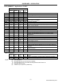
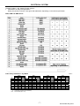
ADR SUMMARY - Applicable to ’08 M/Y
ADR
1/00
3/03
4/03
4/04
5/04
5/05
6/00
8/01
Applicable UDT Series
GWB4D GWB4D
GKB4D CWB4D
400
470
ADR Category
NC
NC
NC
NC
FC
FC
FC
FC
FC
FC
FC
FC
FC
FC
FC
FC
FC
FC
FC
FC
FC
FC
FC
FC
FC
FC
13/00
X
X
X
X
14/02
18/03
30/01
35/02
42/04
43/04
FC
FC
FC
FC
X
X
FC
FC
FC
FC
X
X
FC
FC
FC
FC
X
X
FC
FC
FC
FC
X
X
45/01
n/a
n/a
n/a
n/a
46/00
47/00
48/00
FC
FC
FC
FC
FC
FC
FC
FC
FC
FC
FC
FC
49/00
FC
FC
FC
FC
50/00
51/00
61/02
FC
FC
X
FC
FC
X
FC
FC
X
FC
FC
X
64/00
FC(a)
65/00
FC
FC
FC
FC
80/02
83/00
FC
FC
FC
FC
FC
FC
FC
FC
FC
FC
FC
FC
FC
FC
FC
FC
FC(b)
FC
FC(b)
FC
FC(a)
ADR Title
Reversing Lamps
Seats and Seat Anchorages
Seatbelts
Anchorages for Seatbelts
Direction Indicators
Safety Glazing Material
Installation of Lighting and Light Signalling Devices on other
than L-Group Vehicles
Rear Vision Mirrors
Instrumentation
Smoke Emission Control for Diesel Engines
Commercial Vehicle Braking Systems
General Safety Requirements
Vehicle Configuration & Dimensions
Lighting & Light Signalling Devices not covered by ECE
Regulations
Headlamps
Retroreflectors
Devices for Illumination of Rear Registration Plates
Front and Rear Position (Side) Lamps, Stop Lamps and Endoutline Marker Lamps
Front Fog Lamps
Filament Lamps
Vehicle Marking
Heavy Goods Vehicles Designed for Use in Road Trains & BDoubles
Maximum Road Speed Limiting for Heavy Goods Vehicles and
Heavy Omnibus
Emission Control for Heavy Vehicles
External Noise
Other Legislation
Legend
FC
n/a
X
(a)
(b)
National Code of Practice: Electromagnetic Compatibility
(EMC)
VSB 11 Certification of Road-Friendly Suspension Systems
ECE R29 Cab Strength Requirements
Full Compliance
Not Applicable (no non ECE devices installed)
PCV Compliance only, refer SSM and Body Builders ADR Check List
B-Double approval only
GWB4DA (air suspension) models only
-5-
Issued Date: May 2010
GUIDELINES - LEGISLATION
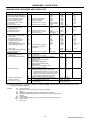
SSM AND BODY BUILDERS ADR CHECK LIST
ITEM
REQUIREMENT
FRONT
1. Main (High) Beam Headlamps
2. Dipped (Low) Beam Headlamps
3. Front Position (Side) Lamps
4. Direction Indicator Lamps
5. Hazard Warning Signals
6. End-Outline Marker Lamps
7. Fog Lamps
8. External Cabin Lamps
LH & RH SIDE
1. Side Repeating Direction
Indicator Lamps
2. Side Retro-Reflectors
3. Side Marker Lamps
MS
MS
REAR
1. Rear Position (Side) Lamps
2. Stop Lamps
3. Rear Retro-Reflectors
4. Direction Indicator Lamps
5. Hazard Warning Signals
6. Reversing Lamps
7. Rear Registration Plate Lamp
8. End-Outline Marker Lamp
MP
MP
MP
MP
MP
MP
MP
MS
9. Fog Lamps
10. Rear Registration Plate Mount
11. Rear Marking Plates
GENERAL ITEMS
1. Vehicle Configuration and
Dimensions
2. General Safety Requirements
3. Brake Air Systems
3. Mechanical Connections
Between Vehicles
4. Trailer Braking System
M
M
M
M
M
M
O
O
{Visibility of these lamps
{must not be restricted
{by bull bar fitment.
on vehicles over 2.1m OW.
on vehicles over 2.1m OW.
M
O
MS
MS
M
MS
M
M
M
M
MS
M
O
O
M
O
M
M
O
O
on vehicles over 6.0m TL.
on vehicles over 2.1m OW
and a TL over 7.5m.
on vehicles over 2.1m OW
except flat tray and tipper
type bodies.
on vehicles over 12.0t GVM.
COLOUR
ADR
White
White
White
Amber
Amber
White or Amber
White or Yellow
Amber
13/00
13/00
13/00
13/00
13/00
13/00
13/00
13/00
Amber
13/00
Amber
Amber to Front
Red to Rear
13/00
13/00
Red
Red
Red
Amber
Amber
White
White
Red
13/00
13/00
13/00
13/00
13/00
13/00
13/00
13/00
Red
n/a
Yellow/Red
13/00
A 6.11
61/02
9.1.1.1, 3
Ref. AVSR 1999 item 119 & VSB 12
Turning Circle
TL, ROH, OH, GC and OW
Electrical Wiring, Connectors & Installations
Exhaust Outlets
External or Internal Protrusions
Field of View
Wheel Guards (Mudguards)
Brake Tubing and Brake Hoses
Sleeper Berths
Television and Visual Display Units
Warning Devices - Audible
Trailer Brake Line: Couplings
Preferential Charging: When additional air
operated items are fitted (i.e. air horns, trailer
brake controls, PTO’s etc.) air supply must be
taken from the delivery (outlet) side of the air
system Pressure Reduction Valve (PRV)
Actuation Timing: Wheelbase extensions
Towbar, Tow Coupling and Fifth Wheel design
and installation requirements
Design, performance and compatibility
requirements
43/04
42/04
35/02
Clause
Appendix
A
A
A
A
A
A
A
6.1
6.2
6.9
6.5
6.6
6.13
6.3
7.1
A 6.5.3
A 6.17
7.2
A
A
A
A
A
A
A
A
6.10
6.7
6.14
6.5
6.6
6.4
6.8, 5.10.2
6.13
5
6
9
10
11
12
14
15
17
18
20
4.1.8
4.7.8, 9
7.12
62/01 up to 12/08
62/02 from 01/09
38/02 up to 12/08
38/03 from 01/09
Note: If items marked ‘M’ or ‘O’ are either supplied or modified the SSMM or Body Builder has the responsibility for ensuring
the vehicles ongoing compliance.
LEGEND
GC
M
m
MP
MS
O
OH
OW
ROH
TL
Ground Clearance
Mandatory (PCV as supplied by UDT has full compliance)
Metres
Mandatory (SSMM, Body Builder has responsibility for positioning)
Mandatory (SSMM, Body Builder has responsibility for supply and positioning)
Optional
Overall Height
Overall Width (excluding mirrors, signalling devices and side mounted lamps)
Rear Overhang
Total Length
-6-
Issued Date: May 2010
GUIDELINES - LEGISLATION
POSITIONING of LAMPS and REFLECTORS: Supplied by UDT
1. Rear Combination Lamp Assembly
Presence
Mandatory and includes the;
A. Rear position lamp
B. Stop lamp
C. Rear and side retro-reflectors
D. Direction indicator lamp
E. Hazard warning signal.
Position
Width (W):
The outer edge of the light-emitting surface of the
indicator lamp must not be more than 400mm from
the extreme outer edge of the vehicle.
Not less than 350mm or more than 900mm above
the ground.
If the structure of the vehicle does not permit
installation within these limits, it is permissible to
increase the upper limit to not more than 1500mm.
Height (H):
Geometric Visibility
Horizontal:
15° above and below the horizontal.
Vertical:
Note:
45° inboard and 80° outboard.
The distance between the rearmost side retro-reflectors and
the rear of the body or equipment must not exceed 1000mm.
2 Reverse Lamp
Presence
Position
Width:
Height:
Length:
Geometric Visibility
Horizontal:
Vertical:
Mandatory
No special requirement.
Not less than 250mm and not more than 1200mm above the ground.
At the rear of the vehicle.
45° to the right and 45° to the left.
15° above and 5° below the horizontal.
3 Rear Registration Plate Lamp
Presence
Mandatory and positioned so that the device illuminates the site of the registration plate.
Note: ADR 13/00, Appendix A clause 5.10.2 states:- For the visibility of white light (excludes the
reverse lamp) towards the rear, there must be no direct visibility of the apparent surface of a white
lamp if viewed by an observer moving within Zone 2 (height 1.0~2.2m above the ground and 15°
left to right) and in a transverse plane situated 25.0m behind the vehicle.
Rear Registration Plate Position (ADR 61/02) - All N (truck) category vehicles:
9.1.1.1. provision must be made for mounting a registration plate to be affixed to the rear of the vehicle so that no part of such
plate is more than 1300mm from the ground.
9.1.1.3. no part of a vehicle, including its standard equipment, regular production options or ‘Equipment’ must be so located as
to obscure any part of the registration plate.
Note: State/territory regulations require a minimum geometric visibility of 45° right to left and 45° upwards.
-7-
Issued Date: May 2010
GUIDELINES - LEGISLATION
ITEMS SUPPLIED at SSM
In accordance with ADR circular 0-4-6 and the respective regulations the supply and positioning of the following
items, where required, is the responsibility of the SSMM or Body Builder.
• Additional side retro-reflectors
• Side marker lamps
• Rear end-outline marker lamps
• Rear registration plate mount
• Rear marking plates (mandatory on vehicles over 12.0t GVM).
-8-
Issued Date: May 2010
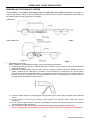
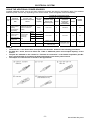
GUIDELINES – BODY INSTALLATION
SUB-FRAME AND BODY INSTALLATION
The rear body must be mounted to the chassis frame using a sub-frame.
Mounting of the sub-frame must conform to the following:
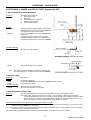
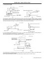
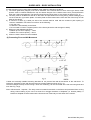
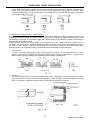
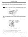
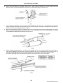
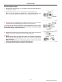
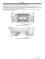
1. SUB-FRAME SHAPE AND MOUNTING
The sub-frame should form a continuous longitudinal channel or RHS. The width of the flange should be 70 ~ 100%
of the flange width of the chassis frame (Fig.1).
Timber should not be used as a sub-frame due to the possibility of shrinkage and warping.
(1) The lower sub-frame flange must be mounted flush with the upper flange of the chassis frame. Do not
mount the sub-frame at an angle to the chassis frame. Connect the right and left sub-frame to each
other by crossmembers, bolsters, or the body proper.
Sliding stoppers should be attached to the sub-frame if necessary (Fig.2).
(2) The sub-frame channel openings should face inward toward the vehicle longitudinal centreline.
(3) Align the sub-frame web surface with that of the chassis frame (Fig.3).
-1-
Issued Date: May 2010
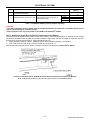
GUIDELINES – BODY INSTALLATION
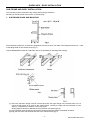
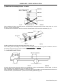
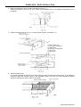
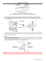
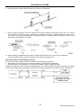
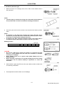
2. FRONT-END SHAPE
The sub-frame combined with the chassis frame may have a point where the rigidity suddenly changes, increasing
the possibility of stress concentration on the chassis frame. To reduce the possibility of stress concentration, shape
the front end of the sub-frame so that its rigidity gradually decreases. Also extend the front end of the sub-frame as
far forward as possible. See Figs. 4, 5, 6 and 7 for examples of sub-frame front-end shapes.
It is recommended that the sub-frame shown in Fig. 4, 5 or 6 be used wherever possible. If the body design or
other factors preclude the use of these, Fig. 7 should be used.
When mounting a tank body or other highly rigid body, use one of the shapes in Fig. 4, 5 or 6.
Use a steel spacer to compensate for any uneven surface such as that caused by a gusset on the chassis frame.
Avoid using semi-elastic spacer material.
When using a spacer between the frame and chassis frame, install the spacer as shown in Fig. 9.
-2-
Issued Date: May 2010
GUIDELINES – BODY INSTALLATION
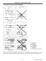
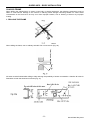
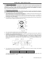
3. POSITIONS OF FRONT- END REINFORCEMENT
The points of the chassis frame where its rigidity changes (e.g., crossmember, gusset and reinforcement) must not
be located with the front end (contact point) of the sub-frame or the head and tail of any reinforcement (Fig. 11).
-3-
Issued Date: May 2010
GUIDELINES – BODY INSTALLATION
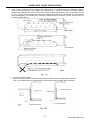
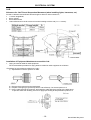
4. MOUNTING BRACKETS
The use of mounting brackets to secure the sub-frame is preferred to U-bolts. If a highly rigid body such as a tank
body or closed van body is to be mounted, it is strongly recommended that spacers be used in combination with
mounting brackets (Fig. 12). Sufficient spring washers should be used with the connecting bolt.
Install the mounting brackets to the chassis frame using bolt nut or rivet attachments at sufficient intervals. Do not
weld.
5. LOCATION PLATES
The sub-frame cannot be securely mounted to the chassis frame using locating plates only. When employing
locating plates use U-bolts or mounting brackets. Closely align the front of the sub-frame with the chassis frame
using the U-bolts or mounting brackets (Fig. 12). Do not use locating plates for mounting a body having a high
centre of gravity or concentrated load. Never use a locating plate for sub-frame mounting of a tank body, dump
body, concrete mixer body, van body, etc. Locating plates are not recommended for vehicles operating on rough or
winding roads.
-4-
Issued Date: May 2010
GUIDELINES – BODY INSTALLATION
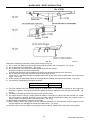
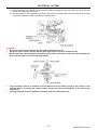
6. COMBINATION WITH CHASSIS FRAME
To be effective, the sub-frame must be securely attached to the chassis frame. “U-Bolts”, “mounting brackets”,
“locating plates”, etc. are normally used to connect the sub-frame to the chassis frame (Fig. 14). Never affix flanges
directly to each other by welding or by bolt-nut attachment.
(1) “U-Bolt” Mounting
A simple method that is frequently used for attaching the body is U-bolts. This is not a recommended method for
body mounting because:
• The load is carried on the top flange, not the web.
• The runner stiffens the frame thus reducing the flexibility along part of the frame length.
• The U-bolts holding the runners are often over tightened causing the frame flange to buckle. Once buckled, the
flanges have their strength greatly reduced.
• When the metal spacers are positioned between the top and bottom flanges to stop the flange buckling, local
stiffening occurs with resultant loss of flexibility.
• Fixing of the body relies on friction and high clamping forces, with no positive location. However tight the Ubolts are when fitted, they work loose and the body is then free to slide on the frame.
• Spacer shrinkage and wear over a period of time can occur and the body mounting becomes loose. Often Ubolts are over tightened at this time to prevent recurrence and frame distortion results.
-5-
Issued Date: May 2010
GUIDELINES – BODY INSTALLATION
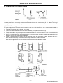
If U-bolt mounting is to be used, then installation must satisfy the following conditions:
1) The frame (particularly flanges) must not be distorted. If the vehicle does not have a box type frame, metal
spacers must be inserted between the top and bottom flanges of the chassis frame rail to prevent distortion
when the U-bolts are tightened. The spacers should be secured in place by the U-bolts as shown in Fig. 15.
2) The body must be located fore and aft on the frame and prevented from moving during violent braking by the
use of at least four (4) location plates. A location plate must be located at the front and rear of the body on both
sides of the vehicle.
3) A minimum of three (3) U-bolts per side of the chassis shall be used with the maximum pitch spacing of
1750mm. Installation of U-bolts must conform to the following:
• Lock the nuts.
• Install the U-bolt vertically to the frame.
• Do not install a U-bolt in a tapered portion of the frame (where the web changes in width).
4) Minimum U-bolt diameters shall be:
• Bodies up to 2 tonne capacity – 12mm
• Bodies over 2 tonne capacity – 16mm.
5) Class 4.6 steel U-bolts are recommended.
(2) Preventing Fore-and-Aft Movement
U-bolts and vertically installed mounting brackets do not prevent fore-and-aft movement of the sub-frame. To
reduce the possibility of fore-and-aft movement use locating plates as shown in Fig. 16.
The frame flanges of dump trucks having a short rear overhang, can be connected at the rear end using bolts and
nuts. See Fig. 16-(3).
Note: VSB 6 section J requires, “The body must be located fore and aft on the frame and prevented from moving
during violent braking by the use of at least four outrigger brackets or fishplates (i.e. location plates). A
bracket or fishplate must be located at the front and rear of the body on both sides of the vehicle”.
-6-
Issued Date: May 2010
GUIDELINES – BODY INSTALLATION
(3) Sub-Frame Connecting Devices - Location
When installing sub-frame connecting devices, avoid damage to wiring harnesses, hoses, tubes, pipes, etc., which
are on or near the chassis frame.
To reduce stress concentration, do not connect the chassis frame to the front of the sub-frame (Fig. 17).
Avoid connecting the sub-frame in shaded areas shown in Fig. 18.
When making holes and welding the chassis frame for mounting brackets and locating plates installation, follow the
procedure described under the captions entitled Drilling the Frame and Riveting
7. LONG WHEELBASE TRUCK
A highly rigid sub-frame should be used on long wheelbase trucks to avoid deflection. Channel steel, lip channel
steel and RHS can be utilized. DO not use a wooden sub-frame.
When a side gate centre pillar is installed on a drop side gate body, the pillar should be located ahead of the centre
of the rear wheels, by at least 760mm to prevent rear overhang deflection (Fig.19).
-7-
Issued Date: May 2010
GUIDELINES – BODY INSTALLATION
CHASSIS FRAME
When drilling the chassis frame to mount a rear body or special equipment, the following precautions must be
taken to avoid serious damage to the vehicle or reducing frame strength. Mounting should not cause stress
concentration in the frame such as may occur from improper location, size or finishing of holes or by improper
riveting.
1. DRILLING THE FRAME
When drilling the frame, use an ordinary twist drill. Do not use a torch (Fig. 20).
All holes must be finished after drilling to help reducing the possibility of stress concentration. Chamfer all holes for
fitted bolts on both bolt head and nut faces (Fig. 21).
-8-
Issued Date: May 2010
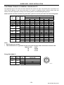
GUIDELINES – BODY INSTALLATION
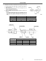
Observe the following precautions in drilling holes. Refer to (Fig. 22):
1) Do not notch the upper and lower flanges of the side rail, gusset, and crossmember – Fig. 22 (b).
2) Do not drill holes in crossmembers – Fig. 22 (b).
3) Do not drill holes in the upper and lower flanges of the side rails except,
(a) holes to install the end crossmember and
(b) holes near the frame end to install bolts to reduce fore-and-aft movement of the sub-frame.
4) Do not drill holes in the upper and lower portions of the side rail web.
In the case of a 539 MPa {55 kgf/mm²} tensile steel frame no part of the holes is to be within 20% of the frame
height – Fig. 22 (a).
5) Holes must not be drilled within 80mm of the perpendicular bending lines of the side member – Fig. 22 (c).
6) The maximum hole diameter should be as follows:
Model
GKB, CWB, GWB Series
Max Diameter
17mm
7) The pitch between two hole centres should be at least 55mm or 4.5 times the diameter of the larger hole,
whichever is greater. This rule should also be applied to the pitch between a new and the existing hole – Fig.
22 (a).
8) The edge of the holes should be more than 30mm from any weld.
9) No more than three holes in a series should be drilled in a vertical line. lf three holes are required in a vertical
line; the maximum diameter should be 15mm for GKB, CWB and GWB series heavy duty models. Avoid a
series of holes in a horizontal line whenever possible – Fig. 22 (a).
10) Drill all holes perpendicular to the face to be drilled.
11) When drilling a hole in the gusset for U-bolt sub-frame mounting, the hole diameter should be 20mm or less
and the distance from the edges should be more than 30mm – Fig. 22 (b).
12) Drill the holes as far as possible from existing holes in the flange, welds and the end portion of the gusset.
-9-
Issued Date: May 2010
GUIDELINES – BODY INSTALLATION
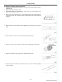
2. RIVETING
Cold hydraulic riveting, rather than hot riveting, is strongly recommended (Scale produced during hot riveting
remains on the surface or a gap is made in the rivet hole, which may cause loosening.). When hot or manual
riveting is necessary, carefully inspect the finish after tightening the rivet.
Always use rivets on areas of the chassis-frame subject to shearing force. Protect rivets from direct tension. When
rivets are used extensively on the vehicle frame, jointly bore the frame and parts to be installed. Rivet holes should
be staggered, and not in a vertical line (Fig. 23).
- 10 -
Issued Date: May 2010
GUIDELINES – BODY INSTALLATION
MECHANICAL CONNECTIONS BETWEEN VEHICLES
1) Towbars, Tow Couplings and Fifth Wheels
The design, installation and marking must conform to the listed ADR’s and their associated Australian
Standards:
ADR
Title
Requirements
35/02
Commercial Vehicle Braking Systems
Section 4, clause 4.1.8 Brake Line Couplings
42/04
General Safety Requirements
Section 9, clause 9.2 Electrical Connections
62/01
Mechanical Connections Between Vehicles
Vehicles with a Compliance Date up to 12/08
62/02
Vehicles with a Compliance Date from 01/09
For installation guidelines, refer to VSB 6; section P Tow Coupling/Fifth Wheels.
Note: Effective Jan-09, the AS/NZS standards quoted in ADR 62/02 take precedence over the AS standards
quoted in VSB 6.
WARNING: GKB & GWB series equipped with factory installed fifth wheel angles.
If the fifth wheel angles are removed to facilitate body/equipment installation, to ensure the ongoing
integrity of the frame structure, the attaching bolts MUST be refitted and tightened to the specified
tightening torque published in the UDTC Service Manual.
LIFTING DEVICES
1) Cranes
Refer to VSB 6; section Q Vehicle Mounted Lifting Systems – Slewing.
2) Tailgate/Platform Loader
Refer to VSB 6; section R Vehicle Mounted Lifting Systems – Non-Slewing.
- 11 -
Issued Date: May 2010
GUIDELINES – BODY INSTALLATION
PRECAUTIONS DURING ELECTRIC WELDING
1. Protection of Electronic Equipment
Units such as a tachograph or radio with a built in clock are directly connected to the battery, and many
electronic devices that have a low resistance against high voltage are used for the controllers such as engine,
ABS, EBS, EHS, and ESCOT. When performing electric welding, there is the danger that electric current from
the welding machine may flow back through the grounding circuit and damage these components. Be sure to
follow the procedure below when performing electric welding.
1) Turn the ignition switch to OFF.
2) Disconnect the battery (–) terminal. Be sure to insulate the removed terminal from the (+) terminal to
prevent a short.
3) It is also recommended to disconnect all ECU’s in the vehicle
Engine ECU: On the engine block.
Brake ECU: In front of the gear lever under the dash.
Rear Axle Modulator: Adjacent to the rear axle/s mounted on the chassis.
Transmission ECU: ESCOT behind the LH lower dash panel, AutoShift ® on the transmission.
4) Establish the grounding for the welding machine near the portion to be welded.
5) After welding, reconnect the ECU’s and battery (-) terminal in the reverse sequence of removal.
2. Welding Electrode
A low hydrogen electrode conforming to either the AWS A5.1 E7016-1 H4~H8 or AS/NZS 1553.1 E4816-4
H5~H10 standard and suitable for welding the listed frame material is recommended.
GKB
CWB
GWB Series
SPFH540 High tension steel plate having a tensile strength of 539 MPa {55 kgf/mm²}
Typical commercially available products are the BOC Smootharc 16, Cigweld Ferrocraft 16TXP-HS, Lincoln
Conarc 51 and WIA Austarc 16TC manual arc welding electrodes.
3. Welding Procedure
To be conducted in accordance with the guidelines and Australian Standards nominated in VSB 6, section H
Chassis, items 5.7 General Precautions – Welding of Frame Rails, and 5.8 Welding Requirements and the
following manufacturers guidelines.
(1) General
The chassis frames of UD Trucks are of a riveted and/or bolted construction. Therefore, avoid welding any
equipment to the frame thoughtlessly. Caution should be given to a frame of high tensile steel which is easily
affected by heat and may decrease in strength if improper welding is done.
Electric arc welding should be used for welding the frame and the following precautions should be exercised.
1. Do not perform tack welding to temporarily attach equipment. Cracks appear easily, and the occurrence of
stress concentration is possible.
2. The welding surface should be well cleaned beforehand. Grease, paint, water, rust, dust and any other
foreign matter left on the welding surface could easily make blowholes and cracks.
3. Welding slag on each layer should be completely eliminated. Slag inclusion will cause a decrease in
welding strength and fatigue resistance.
4. Select an appropriate welding electrode, welding current and welding speed so that any defective welding
is prevented. Some typical defects of electric arc welding are shown in the next table.
Corrective measures to be taken are also shown for reference.
Defect
Incomplete
penetration
Undercut
Slag
Inclusion
Possible Cause
Corrective Measure
1) Inappropriate welding electrode moving speed.
Make the welding speed appropriate, and prevent slag from
getting ahead of the molten pool or arc.
Select the correct current for the welding condition.
Enlarge the groove angle, or select an electrode diameter
according to the angle.
Maintain the proper electrode angle and operation.
Decrease the electrode operation speed.
Decrease the weld current.
Select the most appropriate electrode for the welding condition.
Completely remove the slag from the previous layer.
2) Welding current is too low.
3) Groove angle is narrow.
1) The welding electrode inclination or the
electrode operating speed is inappropriate.
2) Welding current is too high.
3) Improper welding electrode.
1) Imperfect removal of slag from the previous
layer.
2) Improper electrode operation.
3) Defective design.
- 12 -
Increase the current a little, and operate the electrode properly.
Redesign for easy welding operation.
Issued Date: May 2010
GUIDELINES – BODY INSTALLATION
1) Welding current is too high and the electrode
diameter is too large.
2) Poor weld sequence, thick weld bead.
Bead poor in
appearance
3) Electrode operation speed is improper.
Blowhole
4) Slag is improper in covering weld metal
5) Improper electrode is selected.
1) Excessive current and improper electrode
operation.
2) Parent metal is too thick or quickly cooled
3) Oil, paint or rust is on the welded joint.
4) The electrode is humid.
5) Material galvanised
1) Parent metal contains a high degree of alloy
elements such as manganese.
2) Welded joint is too rigid
3) Welding electrode is defective or humid.
Crack
Pit
4) Welding performed with excessive current or
an excessively high speed.
5) Material is too thick or quickly cooled.
6) Parent metal containing too much sulphur.
1) Parent metal containing too much carbon
and/or manganese.
2) Parent metal is too thick or quickly cooled.
3) Parent metal containing too much sulphur.
Select a current and electrode diameter according to the parent
metal.
Follow the proper welding sequence, operate the electrode
correctly.
Select an electrode operation speed enabling slag to grow from
under the molten pool.
Select an electrode with viscous slag.
Select the most appropriate electrode for the welding condition.
Make the arc longer, and perform proper weaving (max. weaving
is 3 times as large as the electrode core diameter).
Perform proper preheating.
Clean the welded joint well.
Store electrodes in a dry condition and pre-condition in
accordance with the manufacturers recommendations.
Due to oxidising zinc, weld with an electrode using a flux of
ilmenite or cellulose. For complete removal of the blowholes,
remove all plating from the groove and parent metal adjacent to
the weld face beforehand.
Preheat, post heat and ensure a low hydrogen electrode is being
used.
Perform preheating and peening.
Use a correct electrode, that has been stored and pre-condition in
accordance with the manufacturers recommendations
Perform welding at the proper current and at the proper speed.
Preheat, post heat and ensure a low hydrogen electrode is being
used.
Use a welding electrode of low sulphur
Use a welding electrode of similar alloy to parent metal.
Perform preheating and post heating.
Use a welding electrode of low sulphur
5. The desirable power for electric arc welding is DC electrode positive. In manual welding, by the use of the
AC conformable coated electrode, AC is acceptable.
6. In order to minimise the welding residual stress, perform preheating (warm the parent metal up to
approximately 100°C with a burner). It is recommended that peening with a peening hammer be performed
after welding, post heating should also be used when the ambient temperature is below 20°C.
(2) Positions to be Welded – Chassis Frame
In any UD vehicle, welding should be performed as far away as possible from the positions liable to high
bending moment, high bending stress, or stress concentration (e.g. crossmember end, gusset end, spring
bracket, and group of holes).
Welding to any gusset or crossmember is prohibited.
1. It is strictly prohibited to weld anything to the under surface of the lower flange of the side rail within the
wheelbase.
2. In the case of steel with a high tensile strength of 539 MPa (55 kgf/mm²).
In addition to the welding prohibition range in Fig. 3-12, welding to the outside of the upper flange is also
prohibited.
- 13 -
Issued Date: May 2010
GUIDELINES – BODY INSTALLATION
3. A short weld zone is liable to harden, due to quick cooling and potentially crack. Therefore, the bead length
should be at least 30mm. Defects can occur easily at the starting and ending points of welding; Thus,
caution should be taken. A corner of the object to be welded must not coincide with the starting and ending
points of the welding (Fig. 3-13).
(3.1) Extension of Chassis Frame – Rear Overhang
If the load space projects more than 1.5 the times final chassis depth and unless the body structure is self
supporting at full load, extend the chassis frame. It is important to consider the weight distribution and prevent
overloading the rear axle. The thickness, shape and material quality of the extension material used should be
similar to that of the chassis frame.
If the extension exceeds the frame height or the extension is under concentrated load, reinforcement is
necessary. The reinforcement should be similar to the frame in quality. When joining the extension material to
the original frame, perform continuous butt-welding by following the procedures described below. When
welding portions in an overhead position, be careful to prevent a shortage of weld penetration.
1. Groove shape
In order to minimise thermal deformation and penetration shortage, it is recommended that an X type
groove be used and that welding be performed on both the front and back sides. When a V type groove is
adopted, back chipping is strongly recommended unless welding a double frame.
2. Finishing
On a butt-welded portion, provide a weld reinforcement. After completing the welding, perform the finishing
work. Use a grinder to finish the welded portion smoothly in order to make it even with the parent metal and
with no undercutting. Illustration below shows the area where for finishing is required.
- 14 -
Issued Date: May 2010
GUIDELINES – BODY INSTALLATION
3. When the extension amount is within the frame height (ℓ < h)
Follow the directions given in Fig. 3-16. When a concentrated load is not applied, reinforcement is not
necessary.
4. Follow the directions given in Fig. 3-17 when reinforcement is required (ℓ > h)
5. With the double frame
It is strictly prohibited to weld the inner channel and the outer channel at the same place. In providing the
extension, follow the directions given in the illustration below. The inner and outer extension materials
should be joined at the web by rivets or plug welds.
- 15 -
Issued Date: May 2010
GUIDELINES – BODY INSTALLATION
(3.2) Cutting of the Rear Overhang
When it is inevitable, in mounting the rear body or a fifth wheel, cut the rear overhang accordingly giving
consideration to weight distribution. If the frame is cut by gas, the cut portion will be extremely hot; so be
careful it does not damage anything surrounding it. It is important not to leave the cut surface as it is, but finish
the surface smoothly with a grinder. Be sure to install an end crossmember. For its installation, use rivets or
M12 (7T) bolts and nuts tightened to the correct torque specification.
(3.3) Reinforcement of the Side Member
Generally, when installed with a sub-frame the chassis frame does not require any reinforcement. However,
when mounting a specific body or meeting a specific user condition that requires reinforcement to be added to
the chassis side members, follow the instructions below:
1. The standard section of the reinforcement plate should be “L“ shaped; the thickness should be less than
that of the side member but more than 40% of its thickness.
Reinforcement using an “]” shaped section is capable of improving strength. However, if its installation is
not precise, it may create a gap on the side member flange and cause a severe defect. Thus this type of
reinforcement is not recommended.
2. For prevention of stress concentration, the end of the reinforcement plate must be cut off to less than 45°
so that the section undergoes a gradual change (Fig. 3-19).
3. Use a reinforcement material similar to the side member quality.
4. In principle, the “L” shaped reinforcement should be installed on the flange with tensile stress. (Within the
wheelbase, the tensile side is the lower flange.)
5. The end of the reinforcement should not be aligned with any existing chassis frame rigidity changing point
(end of existing reinforcing) or a concentrated load input point. In other words, the starting and ending
points of the reinforcement should be sufficiently separated from, or sufficiently overlapped with, the
existing reinforcement end, crossmember end, spring bracket, cab back, and sub-frame starting point, etc.
(Fig. 3-20).
6. The reinforcement should be desirably installed so that it is joined on the web by riveting. The standard
rivet and rivet hole diameters are as follows
Model
GKB, CWB, GWB Series
Rivet Diameter
13mm
Rivet Hole Diameter
14mm
The edge distance between the rivet hole and the reinforcement plate end should be at least 25mm, and
the rivet pitch should be 70 ~ 150mm.
- 16 -
Issued Date: May 2010
GUIDELINES – BODY INSTALLATION
7. When riveting is difficult, perform welding on the web surface. It is desirable to do plug welding by making
holes in the reinforcement. The welding hole should be 20 ~ 30mm in diameter. The edge distance
between the welding hole and the reinforcement end should be at least 25mm, and the hole pitch should
be 100 ~ 170mm. If the specified pitch cannot be satisfied, fillet welding may be applied. For prevention of
thermal deformation, the welding zone should be separated from a bolt hole or rivet hole as much as
possible (at least 30mm).
8. Curvature of reinforcement
Outer: The inside radius Ro (reinforcement) must be smaller than the outside radius ri (frame).
Inner: The outside radius ro (reinforcement) must be larger than the inside radius Ri (frame).
- 17 -
Issued Date: May 2010
GUIDELINES – BODY INSTALLATION
4
Protection of Equipment During Welding
To prevent the effect of welding spatter on the equipment around the welding portion, or damage by welding
heat, be sure to take the following protective measures before welding.
1) When welding in the vicinity of hoses, steel tubes, nylon tubes, harness, electrical parts, and chassis parts,
cover them to protect them from welding spatters and heat.
2) Before doing welding operations in front of the engine, cover the radiator and engine to prevent damage by
welding spatters and heat.
3) Before doing welding operations around the cab, cover the cab to prevent damage by welding spatters and
heat.
4) Before doing welding operations around the chassis suspension, cover the suspension to protect it from
welding spatters and heat.
5) When welding the outside of the frame, check for the presence, or absence of tubes inside the frame.
If tubes exist in the frame, put an insulating shield between the frame and the tubes to block heat and weld
splatter. Especially, nylon tubes as they can be easily damaged or deformed by heat.
5. Other Precautions
1) Avoid welding excessively in one area, or adjacent areas when possible (stagger weld sequence).
2) The welding length should be kept short, however not less than 30mm.
3) Be careful not to cause welding defects such as incomplete welding, undercut, slag inclusion, blowhole,
and crack.
- 18 -
Issued Date: May 2010
GUIDELINES – BODY INSTALLATION
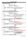
PRECAUTIONS ON VEHICLES EQUIPPED WITH ABS
The ABS is a brake control mechanism which contains electronic circuits processed by a microcomputer.
Therefore, when installing the body near ABS components or remodelling vehicles equipped with ABS, it is
necessary to pay attention to the brake control equipment or electronic parts.
Especially when body installing or remodelling using electric welding, incorrect operations could adversely affect
the parts or equipment. Be sure to observe the following precautions.
1. Prohibited matters
1) Modification of the brake system component parts is prohibited.
2) Use of tyres other than those specified is prohibited.
3) Relocation or remodelling of the ABS unit (modulator, control unit, sensor, etc.), brake piping and ABS
harness is prohibited.
Note: Do not take power for audio system, auxiliary lights, etc. from the ABS harness.
2. Precautions for body installation
1) When installing the following parts, keep them 100mm or more away from the modulator, control unit,
sensors and ABS harness.
• Radio wave transmitters and receivers and related antennas and harness.
• Motors, relays, etc. which produce electrical noise.
2) When electric welding is used at the body installation, turn the ignition switch to OFF and disconnect the
ECU’s and battery ground terminal.
3) After finishing the body installation, carefully check the piping and harness for damage.
4) Perform the normal ABS inspection. For procedures of the ABS inspection, refer to the UDTC Service
Manual.
The main procedure is as follows:
• Check with a self diagnosis function.
• Drive the vehicle on four/six free rollers or drive on actual roads, and apply brakes to check for the
operation of ABS.
5) Other inspections
• If the vehicle is equipped with electrical equipment such as radio transmission devices etc. which are
used during driving, perform ABS inspection while the equipment is operating.
• If the vehicle is equipped with electrical equipment such as a tailgate lifter etc. which is used while the
vehicle is at a stop, operate the equipment with the ignition switch turned ON or the engine operating and
check the ABS for incorrect operation or the warning light for illumination.
- 19 -
Issued Date: May 2010
GUIDELINES – BODY INSTALLATION
PRECAUTIONS ON VEHICLES EQUIPPED WITH EBS
The EBS is a brake control mechanism which contains electronic circuits processed by a microcomputer.
Therefore, when installing the body near EBS components or remodelling vehicles equipped with EBS, it is
necessary to pay attention to the brake control equipment or electronic parts.
Especially when body installing or remodelling using electric welding, incorrect operations could adversely affect
the parts or equipment. Be sure to observe the following precautions.
1. Prohibited matters
1) Modification of the brake system component parts is prohibited.
2) Use of tyres other than those specified is prohibited.
3) Relocation or remodelling of the EBS unit (ABS modulator, control unit, sensor, axle modulator,
proportional relay valve, solenoid relay valve, etc.), brake piping and EBS harness is prohibited.
Note: Do not take power for audio system, auxiliary lights, etc. from the EBS harness.
2. Precautions for body installation
1) When installing the following parts, keep them 100mm or more away from the ABS modulator, control unit,
sensors, axle modulator, proportional relay valve, solenoid valve and EBS harness.
• Radio wave transmitters and receivers and related antennas and harness.
• Motors, relays, etc. which produce electrical noise.
2) When electric welding is used at the body installation, turn the ignition switch to OFF and disconnect the
ECU’s and battery ground terminal.
3) After finishing the body installation, carefully check the piping and harness for damage.
4) Perform the normal EBS and ABS inspection. For procedures of the EBS and ABS inspection, refer to the
UDTC Service Manual.
The main procedure is as follows:
• Check with a self diagnosis function.
• Drive the vehicle on four/six free rollers or drive on actual roads, and apply brakes to check for the
operation of EBS and ABS.
5) Other inspections
• If the vehicle is equipped with electrical equipment such as radio transmission devices etc. which are
used during driving, perform ABS inspection while the equipment is operating.
• If the vehicle is equipped with electrical equipment such as a tailgate lifter which is used while the vehicle
is at a stop, operate the equipment with the ignition switch turned ON or the engine operating and check
the EBS for incorrect operation or the warning light for illumination.
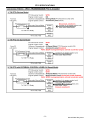
PRECAUTIONS ON VEHICLES EQUIPPED WITH ESCOT
The ESCOT is a transmission control mechanism which contains electronic circuits processed by a microcomputer.
Therefore, when installing the body near ESCOT parts or remodelling vehicles equipped with ESCOT, it is
necessary to pay attention to the transmission control equipment or electronic parts.
Especially when body installing or remodelling using electric welding, incorrect operations could adversely affect
the parts or equipment. Be sure to observe the following precautions.
1. Prohibited matters
1) Relocation or remodelling of the air tubing and electrical harness and connectors.
Note: Do not take power for audio system, auxiliary lights, etc. from the ESCOT harness.
2) Modification of transmission or gear shift unit.
3) Modification of clutch, clutch booster, or clutch pedal.
4) Use of a differential ratio or tyre size other than those specified is prohibited.
2. Precautions for body installation
1) When electric welding is used at the body installation, turn the ignition switch to OFF and disconnect the
ECU’s and battery ground terminal.
2) Some ESCOT related clutch and transmission components require periodical adjustment and
maintenance. Therefore, provide adequate clearance for access and serviceability on top of and around
the transmission and clutch area. Attachments (such as a tool box) in the area should be easily removed.
3) Some ESCOT related parts require adjustment after installation. Perform an operation check of them in
accordance with the UDTC Service Manual.
- 20 -
Issued Date: May 2010
GUIDELINES – BODY INSTALLATION
PRECAUTIONS ON VEHICLES EQUIPPED WITH AUTOSHIFT
Autoshift is a transmission control system which contains electronic circuits processed by a microcomputer.
Therefore, when installing the body near Autoshift parts or remodelling vehicles equipped with Autoshift, it is
necessary to pay attention to the transmission control equipment or electronic parts.
Especially when body installing or remodelling using electric welding, incorrect operations could adversely affect
the parts or equipment. Be sure to observe the following precautions.
1. Prohibited matters
1) Relocation or remodelling of the air tubing and electrical harness and connectors.
Note: Do not take power for audio system, auxiliary lights, etc. from the Autoshift harness/s.
2) Modification of transmission or gear shift unit.
3) Modification of clutch, clutch booster, or clutch pedal.
4) Use of a differential ratio or tyre size other than those specified is prohibited.
2. Precautions for body installation
1) When electric welding is used at the body installation, turn the ignition switch to OFF, ensure the
Transmission is powered down, disconnect the vehicle ECU’s and battery ground terminal.
2) Some Autoshift related clutch and transmission components require periodical adjustment and
maintenance. Therefore, provide adequate clearance for access and serviceability on top of and around
the transmission and clutch area. Attachments (such as a tool box) in the area should be easily removed.
3) Some Autoshift related parts require adjustment after installation. Perform an operation check of them in
accordance with the UD Trucks – Autoshift Service Manual Supplement AUS000183
PRECAUTIONS ON VEHICLES EQUIPPED WITH EHS (hill start assist device)
The EHS is a brake control mechanism which contains electronic circuits processed by a microcomputer.
Therefore, when installing the body near EHS components or remodelling vehicles equipped with EHS, it is
necessary to pay attention to the brake control equipment or electronic parts.
Especially when body installing or remodelling using electric welding, incorrect operations could adversely affect
the parts or equipment. Be sure to observe the following precautions.
1. Prohibited matters
1) Modification of the brake system component parts is prohibited.
2) Use of tyres other than those specified is prohibited.
3) Relocation or remodelling of the EHS unit (EHS valve, control unit, clutch stroke sensor, clutch hydraulic
pressure switch, vehicle speed sensor, etc.), brake piping and EHS harness is prohibited.
Note: Do not take power for audio system, auxiliary lights, etc. from the EHS harness.
2. Precautions for body installation
1) When installing the following parts, keep them 100mm or more away from the EHS valve, control unit and
EHS harness.
• Radio wave transmitters and receivers and related antennas and harness.
• Motors, relays, etc. which produce electrical noise.
2) When electric welding is used at the body installation, turn the ignition switch to OFF, and disconnect the
ECU’s and battery ground terminal.
3) After finishing the body installation, carefully check the piping and harness for damage.
4) Perform the normal EHS inspection. For procedures of the EHS inspection, refer to the UDTC Service
Manual.
The main procedure is as follows:
• Check with a self diagnosis function.
• Check the operation of EHS while driving the vehicle.
5) Other inspections
• If the vehicle is equipped with electrical equipment such as radio transmission devices etc. which are
used during driving, perform EHS inspection while the equipment is operating.
• If the vehicle is equipped with electrical equipment such as a tailgate lifter etc. which is used while the
vehicle is at a stop, operate the equipment with the ignition switch turned ON or the engine operating and
check the EHS for incorrect operation or the warning alarm for activation.
- 21 -
Issued Date: May 2010
GUIDELINES – BODY INSTALLATION
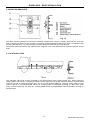
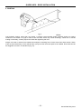
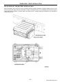
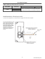
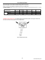
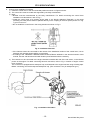
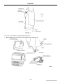
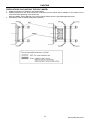
RELOCATION OF THE BATTERY OR RELAY BOX
When the battery and/or relay box must be relocated during the body installation, install the battery relay box with
the face having the water drain hole downside as shown in the figure below. If it is installed with the face having the
water drain hole to the side, or upside, water may enter the box, causing trouble and damage to the components
inside the relay box.
- 22 -
Issued Date: May 2010
GUIDELINES – BODY INSTALLATION
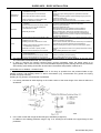
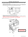
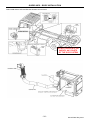
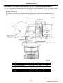
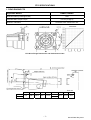
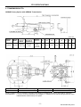
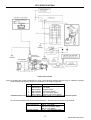
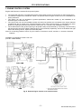
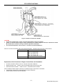
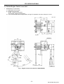
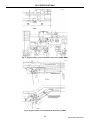
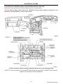
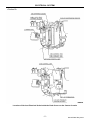
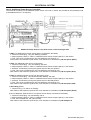
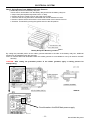
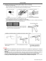
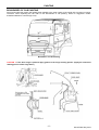
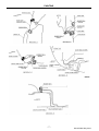
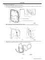
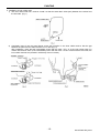
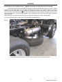
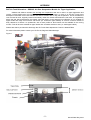
PRECAUTIONS FOR BODY INSTALLATION AROUND THE AdBlue® (urea water solution) TANK
1. Installation of body and/or equipment
When installing a body and/or equipment around the AdBlue tank, be careful not to cover the AdBlue filling hole
(cap) with the body and/or equipment. Provide a clearance around the cap as shown in the figure below to
allow the AdBlue cap to be removed and replaced and the filling nozzle to be inserted.
Example shown Japanese model
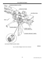
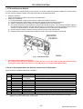
2. AdBlue tank, piping, pump module, dosing module and SCR muffler
The AdBlue tank, piping parts, pump module, dosing module and SCR muffler are installed for the purpose of
making the vehicle compliant to the emission gas regulations (ADR 80/02).
WARNING: DO NOT relocate any parts or modify their connecting piping hoses in any way or for any
reason. To do so will void the vehicles ADR emission compliance (ADR 80/02).
CWB Series: SCR Layout shown
DO NOT RELOCATE OR
MODIFY ANY PARTS
OF THE SCR SYSTEM
- 23 -
Issued Date: May 2010
GUIDELINES – BODY INSTALLATION
GKB, GWB Series: SCR and Exhaust System Layout shown
DO NOT RELOCATE OR
MODIFY ANY PARTS
OF THE SCR SYSTEM
- 24 -
Issued Date: May 2010
GUIDELINES – BODY INSTALLATION
The AdBlue tank hose connectors are located near the marks ♦ (ref. CWB series illustration). After conducting the
body installation operation around these areas, visually check for the engagement of the connector hooks located
on the AdBlue hose ends regardless of whether the hoses were disconnected.
Link to AdBlue MSDS: http://www.air1.info/en/index.html then select Air1 icon in the LHS panel and follow the
path to Data Sheet then to Air1® (Yara Australia Pty Ltd)
- 25 -
Issued Date: May 2010
GUIDELINES – BODY INSTALLATION
REMODELING THE EXHAUST SYSTEM
The remodelling of the muffler, front engine pipe and ADR 83/00 noise reduction shields is prohibited. To
prevent a fire, adverse effects on the SCR muffler and non conformance to emission regulations the remodelling of
the exhaust system except the tail pipe is prohibited.
CWB Series
GKB, GWB Series
1. Remodelling the tail pipe
When modifying or remodelling the tail pipe, observe the following precautions.
1) The tail pipe shall have the same material (stainless), diameter, surface treatment, etc. as those of Nissan
Diesel genuine parts.
2) Extension or further bending of the pipe may cause an increase in exhaust resistance, reduction of engine
output, increase of fuel consumption, increase in the concentration of exhaust gas, etc. Exhaust back
pressure must not be increased above that of the standard vehicles exhaust system. The bending radius of
the pipe should be more than twice the pipe diameter as shown in the figure below, and the number of
bending portions should be three at maximum.
3) Adopt an elastic support for supporting the tail pipe and use the same support method as the standard
vehicle.
4) For the direction of the tail pipe opening, strictly observe the respective ADR, State and Territory
regulations.
5) Do not install a spark arrestor, because it substantially increases the exhaust pressure and adversely
affects the SCR muffler and engine.
6) Any modification of the vehicles tail pipe will effect the vehicles noise compliance (ADR 83/00).
It is the responsibility of the modifier to ensure the vehicles continued compliance with ADR 83/00.
- 26 -
Issued Date: May 2010
GUIDELINES – BODY INSTALLATION
OTHER
Refer the following sections of this manual for guidelines relating to:
• Chassis Layout
• PTO Specifications
• Electrical System
• Air System
• Painting
- 27 -
Issued Date: May 2010
GUIDELINES – BODY INSTALLATION
TIGHTENING TORQUE OF GENERAL CHASSIS BOLTS
The tightening torque of the bolts and other fasteners that secure the major components parts is specified in the
UDTC Service Manual. In the case where there is no mention of tightening torque, general chassis bolts and
fasteners should be tightened according to the following tables of bolt standard tightening torque.
NOTE: All bolts and nuts are sized using the metric system. Do not use parts other than those designated.
Nominal
Size
Bolt Ø
mm
Pitch
mm
M3
M3.5
M4
M5
M6
3.0
3.5
4.0
5.0
6.0
M8
8.0
M10
10.0
M12
12.0
M14
M16
M18
M20
M22
14.0
16.0
18.0
20.0
22.0
M24
24.0
0.5
0.6
0.7
0.8
1.0
1.25
1.0
1.5
1.25
1.75
1.25
1.5
1.5
1.5
1.5
1.5
2.0
1.5
Standard Tightening Torque: Nm (without lubricant)
Standard Bolt
Bolt with Flange
4T
7T
9T
4T
7T
9T
0.7
1.1
1.6
0.9
1.2
1.5
0.9
1.5
2.0
1.2
2.0
2.5
1.5
2.5
3.5
2.0
3.0
4.0
2.9
5.0
7.2
4.0
7.0
9.0
5.1
8.4
12.0
7.0
11.0
13.5
13
21
29
17
28
35
13
22
31
17
28
35
25
41
59
35
55
80
25
43
62
35
55
80
42
71
98
55
100
130
46
77
108
65
100
130
74
127
177
100
170
210
108
186
275
130
250
290
167
275
392
210
350
420
226
382
549
290
490
640
304
510
736
420
720
880
275
461
667
284
481
686
-
NOTE
• Special parts are excluded.
• This standard above is applicable to bolts having the following marks embossed on the bolt head.
Material Code
4T
7T
9T
Mark
4 or 40
7 or 70
9 or 90
Flange Bolt (Mark F)
Nominal
Size
M8
Bolt Ø
mm
8.0
M10
10.0
M12
12.0
Pitch
mm
1.25
1.25
1.5
1.25
1.5
Recommended Tightening
Torque: Nm
27
59
54
118
108
- 28 -
Issued Date: May 2010
-1-
WARNING: If the fifth wheel angles are removed to facilitate body/equipment installation, to ensure the ongoing
integrity of the frame structure, the attaching bolts MUST be refitted and tightened to the specified tightening
torque published in the NDMC Service Manual.
GKB4DAD (Air suspension)
TYRE SIZE
11R22.5
295/80R22.5 (front)
11R22.5 (rear)
Unit: mm
FHR
1010
1010
FHF
962
964
OH
2963
2965
HEIGHT
235
GC
235
CHASSIS LAYOUT
CHASSIS LAYOUT: GKB4DAD (Air suspension)
Issued Date: May 2010
-2-
CAUTION: Due to rear suspension torsional loadings the wheelbase of this model must not be
shortened to less than 5500mm.
CWB4DAW (Air suspension)
OH
2960
2915
275/70R22.5
Unit: mm
TYRE SIZE
11R22.5
FHR
1031
986
940
HEIGHT
FHF
985
180
GC
225
CHASSIS LAYOUT
CHASSIS LAYOUT: CWB4DAW (Air suspension)
Issued Date: May 2010
-3-
WARNING: If the fifth wheel angles are removed to facilitate body/equipment installation, to ensure the ongoing
integrity of the frame structure, the attaching bolts MUST be refitted and tightened to the specified tightening
torque published in the NDMC Service Manual.
GWB4DLH (Trunnion suspension)
TYRE SIZE
11R22.5
295/80R22.5 (front)
11R22.5 (rear)
Unit: mm
FHR
1098
1098
FHF
#1018
#1020
OH
#2997
#2999
260
GC
260
HEIGHT (# 3 leaf front springs -20mm)
CHASSIS LAYOUT
CHASSIS LAYOUT: GWB4DLH (Trunnion suspension)
Issued Date: May 2010
-4-
WARNING: If the fifth wheel angles are removed to facilitate body/equipment installation, to ensure the ongoing
integrity of the frame structure, the attaching bolts MUST be refitted and tightened to the specified tightening
torque published in the NDMC Service Manual.
GWB4DAH (Air suspension)
TYRE SIZE
11R22.5
295/80R22.5 (front)
11R22.5 (rear)
Unit: mm
FHR
1050
1050
FHF
#1018
#1020
OH
#2993
#2995
260
GC
260
HEIGHT (# 3 leaf front springs -20mm)
CHASSIS LAYOUT
CHASSIS LAYOUT: GWB4DAH (Air suspension)
Issued Date: May 2010
CHASSIS LAYOUT
SECTION MODULUS: GKB4DAD (Air suspension)
SECTION MODULUS: CWB4DAW (Air suspension)
-5-
Issued Date: May 2010
CHASSIS LAYOUT
SECTION MODULUS: GWB4DLH (Trunnion suspension)
SECTION MODULUS: GWB4DAH (Air suspension)
-6-
Issued Date: May 2010
CHASSIS LAYOUT
ALLOWANCE FOR REAR AXLE, SUSPENSION & TYRE ARTICULATION
1. Allowance for Tyre Movement
Suspension
Position
Tyre
H1
H2 11R22.5
S
GKB4DA
Air
Rear
Axle
135
220
183
CWB4DA
Air
Rear/Front Rear/Rear
Axle
Axle
112 (*66)
108 (*62)
194 (*149) 190 (*145)
187 (*187) 188 (*188)
Tyre
Disc Wheel Size
Offset
C
11R22.5
22.5 × 8.25-165, 13TCS
165
GWB4DL
Trunnion
Rear/Front Rear/Rear
Axle
Axle
105
82
201
179
141
141
Tread
T
1838
#1858
Unit: mm
GWB4DA
Air
Rear/Front Rear/Rear
Axle
Axle
61
61
110
110
186
186
Tyre Growth Width
B
279 (*276)
Maximum Width
L
2447 (*2444)
#2467 (*2464)
Note:
• (*) indicates optional 275/70R22.5 tyres CWB4DA model only.
• # indicates the data when optional aluminium wheels are fitted.
• When installing tyre chain, add 50mm to H1 and H2 dimensions.
• The tyre growth width: B indicates the value from JATMA.
-7-
Issued Date: May 2010
CHASSIS LAYOUT
2. Allowance for Rear Axle Movement
1) Trunnion Suspension (GWB4DL)
The figures and table below show the maximum ascending position of the upper torque rod between
frames. Be careful not to cause an interference when installing the body, fuel tanks, rear wheel guards, etc.
Position
L1
633
L2
635
L3
13
L4
23
L5
163.5
Torque
Rod
A
B
C
D
Unit: mm
L
(length)
535
535
535
535
CAUTION
• L3 and L4 = the maximum ascending position of the upper torque rods where the axles are in metallic
contact.
-8-
Issued Date: May 2010
CHASSIS LAYOUT
2) Air Suspension – Full Floating Type (GKB4DA, CWB4DA)
The figures and table below show the maximum ascending position of the upper V-Rod between frames.
Be careful not to cause an interference when installing the body, fuel tanks, rear wheel guards, etc.
GKB4DA 4x2
CWB4DA 6x4
Unit: mm
Height
Position
Setting
Raised
FHR
Normal
Lowered
a) Lowered
H
b) Compressed
Note:
GKB4DA
CWB4DA
1165
1010
940
16
-3
1085 (*1040)
1031 (*986)
974 (*929)
Rr/Rr 0
Frt/Rr -26
Rr/Rr -28
(*) indicates optional 275/70R22.5 tyres
CWB4DA model only.
V-ROD (upper location/torque rod)
CAUTION
• H = the maximum ascending position of the V-Rod when the air suspension is
a) lowered (with no load) and,
b) bump stop rubbers fully compressed (max. vertical travel).
-9-
Issued Date: May 2010
CHASSIS LAYOUT
3) Air Suspension - Semi Floating Type (GWB4DA)
The figures and table below show the minimum clearance required forward of the front/rear axle
suspension mounting bracket and the maximum ascending position of the lateral rod between frames.
Be careful not to cause an interference when installing the body, fuel tanks, rear wheel guards, etc.
Dimensions of Lateral Rod
Position
L
H
A
Unit: mm
GWB4DA
82.5
71
Ft/Rr Axle
Rr/Rr Axle
132.4
126
CAUTION
• H = the maximum ascending position of the lateral rod and indicates when the air suspension is fully
deflated.
- 10 -
Issued Date: May 2010
CHASSIS LAYOUT
ALLOWANCE FOR BODY CLEARANCE, CAB TILT & SUSPENSION MOVEMENT
•
•
To accommodate the moving portion of the cab (cab main body, air intake etc.), on the cab suspension of +/30mm longitudinal, 50mm vertical and 30mm lateral movement, when installing the rear body/equipment
provide a clearance of;
(1) 100mm or more to the moving portion of the cab and
(2) 40mm or more between any fixed chassis parts (fluid reservoir, cab support, rear engine cover etc.).
*When starting to tilt the cab, be careful as the tilt centre raises a maximum of 40mm (i.e. A + 40mm).
Vehicle Model
A: Tilt Centre to Frame
L1: Tilt Centre to Front Axle
L2: Front Axle to Air Intake
L3: Front Axle to Cab Support
L4: Front Axle to 2nd Crossmember
H1: Fame Height
H2: Cab to Frame
n/a = not applicable
GKB4D
99
1257
715
850
n/a
275
1997
- 11 -
CWB4D
77
1257
715
n/a
2258
298
1972
Unit: mm
GWB4D
77
1257
715
850
2243
298
1972
Issued Date: May 2010
CHASSIS LAYOUT
- 12 -
Issued Date: May 2010
PTO SPECIFICATIONS
1. REAR ENGINE PTO
Applicable Models
CWB4D, GWB4D
Reduction Ratio (PTO/engine ratio)
1.00:1
Allowable Max. Output Torque
441 Nm {45 kgf.m}
Direction of Rotation
Clockwise when viewed from rear
PTO Drive Flange Dimensions and Performance Chart
CWB4D
GWB4D
θ°
H1
H2
L1
L2
3.0°
298.0
255.4
681.7
112.0
L3
1576.3
1561.3
Unit: mm
M3
M1
M2
95.4
434.6
43.0
PTO Location
-1-
Issued Date: May 2010
PTO SPECIFICATIONS
2. TRANSMISSION PTO:
GKB4D Factory Option with APR90A Transmission
Unit: mm
Vehicle
Model
GKB4D
Engine
Model
Transmission
Model
APR90A
GB13TB
(10.16~0.75)
PTO Torque
Nm (kgf.m)
{Reduction}
Rotation
Direction
H1
H2
H3
L1
L2
490 (50)
{1.071}
Clockwise
when
viewed
from rear.
275
267.9
158.2
2120
592.9
L3
L4
θ
214.5 207.6 5.0º
PTO Specification and Location
Chassis Model
GKB4D
Part No. PTO Assembly
33300 NA006
Drive Ratio
0.934 x engine speed
Part No. Drive Flange
38211 91213
Supply Condition: The PTO assembly (including drive flange) is installed to the vehicle during UDTC production.
PTO Operation: A control, as per the following circuit diagram, is installed to the vehicle during production when
ordered with the UDTC factory PTO option.
-2-
Issued Date: May 2010
PTO SPECIFICATIONS
PTO Control Circuit
Note: All chassis-cab models incorporate the PTO circuit electrical harness and this may be utilised to operate
locally supplied transmission PTO’s by the addition of the listed components.
1
Qty
1
1
1
1
1
1
Part No.
25165 02Z00
25550 00Z12
26335 30Z07
25312 0Z000
08911 3421A
46411 Z0004
Part Name.
PTO Switch
PTO Relay
Magnetic Valve
1
PTO Clutch Switch
Nut, PTO Clutch Switch1
Stopper, PTO Clutch Switch1
AutoShift models can not be fitted with the PTO clutch switch as it is utilized by the autoshift system.
For connector locations refer to the “Electrical System – Harness Layout” section of this manual,
Illustration
Main Harness RH
Chassis Harness
Connector
MR-18 PTO Relay
MR-103 PTO Clutch Switch
MR-121 PTO Switch
CL-21 PTO Magnetic Valve
-3-
Issued Date: May 2010
PTO SPECIFICATIONS
CWB4D, GWB4D with EATON FULLER Transmission
Vehicle Model
Transmission
CWB4D
RTLO 14913A
RTLO 14913A
RTLO 18918B
RTLO 18918A-AS3
GWB4D
PTO
Allowable Max. Output Torque
Location
Refer to Local Vendor for their Australian Specifications
RHS 6-Bolt PTO opening is not available for AS3 model
Autoshift transmission – Electronic gear override
In certain PTO configurations, an override function to engage a direct drive ratio is required.
To put the transmission into “PTO
mode” locate the unterminated,
Brown / White wire taped to the
harness approximately 300mm
from the main 38way connector
shown must be grounded. The
transmission must also be
enabled by an authorized Eaton
representative to utilize this
function.
Brown / White
Pin #18
Approx 300mm
-4-
Issued Date: May 2010
PTO SPECIFICATIONS
3. ENGINE CONTROL SYSTEM
Engine with Electronic Controlled Fuel Injection System
•
•
The engine with electronic controlled fuel injection system does not have a control lever on the injection pump.
To control the engine from outside the vehicle, an optional external engine control lever unit is available from
UDTC production.
• This feature can also be retrofitted to general specification chassis-cab models, by the installation of an
external engine control lever unit.
• The control lever unit can be installed to either the cab mount position and connected to the engine harness
provided near the air cleaner (Fig. A External Engine Control Lever and Connector), or relocated to any other
position by utilising an extension sub-harness, refer to item “b.2. Control Lever Installation Procedure”.
• The characteristics of the governor (driving or all-speed mode) can be switched by connecting or disconnecting
the two harness connectors cables (called junction A and junction B) respectively, which are located at the right
side of the steering column, adjacent to the brake pedal.
Note: For connecting positions, refer to “Fig. B Location of Junctions A and B”, and item “a. Junction Connection
Patterns”.
Installation of the Engine Control Lever Unit
(Part No. 25960 ND00A)
GKB, GWB
CWB
Fig. A External Engine Control Lever and Connector
-5-
Issued Date: May 2010
PTO SPECIFICATIONS
Fig. B Location of Junctions A and B
CAUTION
• Junctions A and B have no flags. Connect them based on the wire colours.
• There is a harness (with a flag in roman characters) for trouble diagnosis near the Junctions A and B.
Be careful not to connect it to any of the PTO junction connectors.
• For connection patterns, refer to item “a. Junction Connection Patterns”.
Note: For connector locations refer to the “Electrical System – Harness Layout" section of this manual,
Illustration
Main Harness RH
Engine Harness
Connector
MR-102 Junction B-1
MR-111 Junction B-2
MR-112 Junction A-2
MR-134 Junction AB
MR-121 PTO/Governor Switch
E-24
PTO Accelerator Sensor
Explanation of the Functions of Engine Control Parts and Installation
•
•
•
Junctions A and B...Refer to “item a. Junction Connection Patterns”.
Engine Control Lever ... Refer to “item b. External Engine Control Lever Unit”.
PTO and Governor Switch ... Refer to “item c. PTO and Governor Switch”.
Note: Conditions where engine control by the external engine control lever is activated.
• Transmission change lever: Neutral position must be selected.
• Vehicle speed: Vehicle must be stationary.
-6-
Issued Date: May 2010
PTO SPECIFICATIONS
a. Junction Connection Patterns
Notes:
1. PTO switch (incorporates both the PTO and governor switching function)....Part No. 25165 02Z00.
2. Governor switch.....Part No. 25165 02Z02.
3. To switch the governor characteristics from Driving to All Speed mode, the ON or OFF signal of the PTO or
Governor switch is required and in addition, the following conditions must be satisfied.
• Accelerator pedal: Idling position.
• Engine control lever: Idling position (if fitted).
• Transmission change lever: Neutral position must be selected.
• Vehicle speed: Vehicle must be stationary.
Note: If fitted with a transmission PTO the clutch pedal must be depressed and then released, after operation
of the PTO switch, to engage the PTO.
4. When using ENGINE PTO connection pattern 2 both the accelerator pedal and external control lever are
active, the engine speed is determined according to either the accelerator pedal opening degree or the external
engine control lever opening degree, whichever can achieve a higher speed.
5. When fitted with either a PTO or Governor switch, the switch must be in the OFF position before starting the
engine. When the switch is in the ON position, the engine DOES NOT START.
End of Line Programming (EOLP) Parameters- Accelerator Pedal (active/disabled)
When using ENGINE PTO connection patterns 3 and 4 or TRANSMISSION PTO connection patterns 2 and 3 and
the PTO or Governor switch is turned to the ON position, the accelerator pedal function is disabled.
Should the vehicle application require the accelerator pedal function to be active when using one of these
connection patterns, the engine ECU is re-programmable by UDT, via your UD Trucks dealer, to incorporate the
accelerator pedal active function when the PTO or Governor switch is turned to the ON position.
WARNING: Ensure that the PTO or governor switch is turned OFF during driving. If the PTO or governor
switch is in the ON position, the governor characteristic is changed to the operation mode (all-speed).
Driving under such a status is dangerous.
-7-
Issued Date: May 2010
PTO SPECIFICATIONS
-8-
Issued Date: May 2010
PTO SPECIFICATIONS
-9-
Issued Date: May 2010
PTO SPECIFICATIONS
Optional Engine Control Parts Installed During UDTC Production
Engine control parts are supplied in combination as shown in the table below.
To obtain necessary engine control functions, ensure junctions A and B are connected referring to item “a. Junction
Connection Patterns”.
Vehicle Specification
PTO Switch
Specification
Chassis-Cab (std)
Options:
Engine Control Lever
Engine PTO
Transmission PTO (GK)
Governor only
PTO/Governor
Engine
Control
Lever
Supplied
-
Mounting
Bracket
Sub-Harness
for Extension
Junction
A
Junction
B
Supplied
-
Supplied
-
Connected
Connected
Connected
Connected
Disconnected
Connected
Disconnected
Disconnected
Note: All models feature electrical harness connectors MR-121 PTO switch and E-24 PTO accelerator sensor.
CAUTION - Engine Control Lever: The adjusting bolts mounted at two points on the engine control lever
have been set before factory shipment. Do not adjust them.
Fig. D Engine Control Lever
- 10 -
Issued Date: May 2010
PTO SPECIFICATIONS
b. External Engine Control Lever Unit
1. Specification of control lever
1) Idle speed: 430~470 rpm
2) Reaction force of lever
At idle: 1.02 Nm {0.104 kgf.m}
At full speed: 2.00 Nm {0.204 kgf.m}
3) It is recommended that the engine speed, during PTO operation, be set to 1000 rpm or more.
Fig. 1 Engine Control Lever (Part No. 25960 ND00A)
- 11 -
Issued Date: May 2010
PTO SPECIFICATIONS
2. Control Lever Installation Procedure
1) Install the control lever to the recommended position as shown in Figures 4 and 5.
2) The control wire must be routed and supported by the body manufacturer.
3) Note:
• Bracket must be manufactured by the body manufacturer. For detail concerning the control lever
installation hole dimensions, refer to Fig. 1.
• Install the control lever at a position where water is not directly splashed. Especially, in the cases
(including car wash) where water is splashed directly on the coupling in the lever (at the portion A in Fig.
1), put a cover on it.
• Do not install the control lever in the wrong direction as shown in Fig. 2.
Fig. 2 Installation Direction
• If the harness cannot be connected for the reason of the installation location of the control lever, use an
extension sub-harness (24024 04Z01) or equivalent.
• According to the “GENERAL PRECAUTIONS ON ELECTRICAL WIRING” in the electrical section of this
manual, wire the sub harness and install vibration-proof fasteners where necessary.
4) The harness is to be connected to the engine harness located at the rear of the cab mount, in the left rear
portion of the engine. For detail concerning harness connection, refer to “Fig. 6 Location of engine control
lever connector”.
The connector is equipped with a waterproof cap, and fastened to the engine harness using a binding tape.
Before connecting, remove the tape and waterproof cap. (The connector is a 4-pin waterproof type.)
Fig. 3 Installation Procedure
- 12 -
Issued Date: May 2010
PTO SPECIFICATIONS
Fig. 4 Engine Control Lever Installation Dimension (GKB, GWB)
Fig. 5 Engine Control Lever Installation Dimension (CWB)
- 13 -
Issued Date: May 2010
PTO SPECIFICATIONS
Fig. 6 Location of Engine Control Lever Connector
- 14 -
Issued Date: May 2010
PTO SPECIFICATIONS
c. PTO and Governor Switch
If a PTO is added to a vehicle having no PTO switch or if governor switching function is added to a vehicle having
no such function, install the switch in the space provided on the instrument panel.
1. Selection of Switch
There are two kinds of switches (#). Refer to the table below.
2. Sequence of Operation
1) Pull the instrument cluster surround from the instrument panel to remove it.
2) Pull the escutcheon (PTO switch) panel from the instrument panel forward to remove it.
3) Install or replace the switch at the PTO switch installation point on the escutcheon.
4) The switch connector is connected to the S type 8 pin female connector. The connector has been taped to
the harness which branches from the main harness to the escutcheon. Remove the tape and pull out the
connector. A label marked “2” is attached to the harness near the connector for identification.
5) Connect the PTO switch connector with the connector on the main harness side.
6) Install the escutcheon and instrument cluster surround in the reverse sequence of removal.
Fig. 7 Instrument Panel
3. Precautions when Starting the Engine
On a vehicle with the PTO or governor switch, be sure to turn the switch to the OFF position before
starting the engine. When the switch is in the ON position, the engine DOES NOT START.
d. Parts to be Prepared when the External Control Lever is Retrofitted
Parts required for standard chassis-cab installation:
QTY
1
1
1
2
2
4
1
1
2
1
1
Part No.
25960 ND00A
25165 02Z00
25165 02Z02
25614 03Z14
01125 00854
01125 28204
08918 3081A
01935 35004
08117 0201G
01552 30004
01552 00224
24024 04Z01
Part Name
Control lever
Switch
# If required
Sensor bracket
Flange bolt
Flange bolt
Flange nut
Stay
Bolt with washer
Harness clip
Fastener band
Sub-harness
Remarks (Unit: mm)
External Engine Control Lever unit
(#) PTO (with Transmission PTO - refer note)
(#) Governor (with Engine PTO)
For installation of the Engine Control Lever
M8x1.25 L=80, lever and bracket
M8x1.25 L=25, bracket and cab mount
M8x1.25
For installation of the harness clip on the cab mount
For installation of the stay on the cab mount
Sensor bracket, stay on the cab mount
For fixing the harness of the control lever to the engine harness
For extended connection (3.5m)
Note: Refer to the “Transmission PTO” section of this manual for the PTO control circuit and the PTO relay,
magnetic valve and clutch switch components.
- 15 -
Issued Date: May 2010
PTO SPECIFICATIONS
- 16 -
Issued Date: May 2010
ELECTRICAL SYSTEM
See “HD-T wiring diagrams” in the UDTC Service Manual for detailed information on the electrical system.
®
®
NOTE: For more detailed information on the Autoshift components refer to the UDT “Autoshift service
manual supplement” Publication number AUS000183
HARNESS FOR REAR LAMPS
Wiring and Installation of Rear Combination and Registration Plate Lamps
Harness for rear combination and registration plate lamps has surplus harness that enable the extension in body
installation, and the surplus harness is tied in bundles for shipment as shown in the figure below.
At body installation, lay out the harness without sagging and clipped at intervals of 300mm as a standard (ref.
General Precautions on Electrical Wiring). If the remaining harness is tied in a bundle, fix it so that it does not
interfere with the brake piping, fuel piping, etc.
Lamps
Rear combination lamp
Registration plate lamp
Temporary Installation
Position
Rear end of frame
End crossmember
Length of Extension
Harness
Right: 2.0m
Left: 1.2m
Right: 0.5m
Left: 0.5m
0.8m
Harness
Marking
Without
Without
Without
Without
Without
Applied
Models
Rigid
Tractor
All
Position of Rear Combination, Reversing and Registration Plate Lamps
Rear combination, reversing and registration plate lamps, supplied by UDT, all have ADR approval for photometric
performance however their location on the completed vehicle must meet the positional requirements of ADR 13/--,
refer to the “Guidelines – Legislation” section of this manual.
Ensure that the requirements of Appendix A, clause 5.10.2 of ADR 13/-- are also met when considering the location
of the registration plate lamp.
-1-
Issued Date: May 2010
ELECTRICAL SYSTEM
Connection to Spare Circuits in Chassis Harness LH
Two parallel spare circuits are built into the chassis harness from the harness connector box of the cab (LHS) to
the rear of the LH frame. If these built in circuits are to be connected during body installation, connect to the
harness according to the following procedure.
1. When the circuits built into the chassis harness are used:
Cab Side:
As shown in the figure, the harness connector box is placed on the left side under the front cab lid and three
harness bundles are connected to the harness connector box.
Next, as shown in the figure below, if the box cover is removed, you will find two electric wires (red and yellow),
without connectors, for the spare circuits, attached at the back of the second harness bundle from the right with
blue tape.
Note: Refer to the Harness Layout section, chassis harness LH, illustration key CL-7 Spare Wire (cab side).
Location of CL-7: Spare Circuit Wire/s (cab side)
Chassis Side:
The electric wires, without connectors, for the spare circuits on the chassis side are attached to the chassis
harness LH in the left frame rail and identified with blue tape as shown in the figure below.
• CWB Series: LH chassis rail at the back of the 3rd or 4th crossmember.
• GKB/GWB Series: LH chassis rail above the centreline of the rear axle group.
Note: The same colour wires (red and yellow) are used respectively on the cab side and chassis side, the
carrying capacity of each wire is15A and if utilised a fuse must be included in each circuit.
Refer to the Harness Layout section, chassis harness LH, illustration key CL-50 Spare Wire (chassis
side).
-2-
Issued Date: May 2010
ELECTRICAL SYSTEM
Location of CL-50: Spare Circuit Wire/s (chassis side)
Note: CWB Series Illustrated (ref. Harness Layout section for GKB/GWB Series)
2. When an additional harness is passed through the cab rubber grommet (Not available on automated models):
The grommet for body installation is set on the upper portion of the cab harness connector box on the left.
Note: On vehicles fitted with Autoshift ® AMT this rubber grommet is not available for use (it is used for the
AMT harness).
The harness can be passed through the grommet by cutting either the cross section A-A (max. diameter of
7mm) or B-B (max. diameter of 13mm) of the rubber grommet, one of two sizes can be selected depending on
the size of the additional harness.
CAUTION
• When re-installing the grommet or passing a harness through the grommet, seal and install it tightly to
prevent water or drafts from entering.
• To prevent water entry, install the harness from the grommet to the upper position on the interior side
and from the grommet to the lower position on the exterior side.
WARNING: These spare circuits (red and yellow wires) are NOT protected by a fuse. If these spare circuits
are used they MUST be fused individually with fuses having a maximum rating of 15A. Refer the following
Electrical System sections, in this manual, for potential sources of additional electrical power, if required.
-3-
Issued Date: May 2010
ELECTRICAL SYSTEM
LOCATION OF FUSE BOX, RELAY AND OTHER UNITS IN THE CAB
The fuse box, relay and units in the cab are located as shown in the figure below.
CAUTION: When welding, strictly observe the “Precautions during electric welding” instructions in the
“Guidelines – Body Installation” section of this manual.
Location of Various Electrical Units Inside the Dash Cover on the Passenger Side
®
®
NOTE: For more information on the Autoshift components refer to the UDT “Autoshift service manual
supplement” Publication number AUS000183
-4-
Issued Date: May 2010
ELECTRICAL SYSTEM
Location of Various Electrical Units Inside the Dash Cover on the Centre Console
-5-
Issued Date: May 2010
ELECTRICAL SYSTEM
<Portion C>
• Layout of the fuse box in the cab
Blade type fuses and relays are placed as shown in the figure and table below; depending on the vehicle
specification.
GKB, CWB and GWB Series
Chart: Fuse and Relay Installation – By Model
No.
46
45
48
49
50
51
52
53
54
55
56
57
58
59
60
GKB
Fuses
CWB
GWB
No.
31
32
33
34
35
36
37
38
39
40
41
42
43
44
45
GKB
Fuses
CWB
GWB
No.
16
17
18
19
20
21
22
23
24
25
26
27
28
29
30
GKB
Fuses
CWB
GWB
No.
1
2
3
4
5
6
7
8
9
10
11
12
13
14
15
GKB
Fuses
CWB
GWB
No.
61
62
63
GKB
Fuses
CWB
Name
Neutral
Blower
Ign & A/C
Tail Lamp
Accessory
GKB
Relays
CWB GWB
GWB
Installed
-6-
Issued Date: May 2010
ELECTRICAL SYSTEM
<Portion D (relay: 1-24), Portion E (relay: 25-32)>
• Identification of relays and application
Relays are placed as shown in the figure and table below; depending on the vehicle specification.
GKB, CWB and GWB Series
Chart: Relay Installation – By Model
No.
1
5
9
13
17
21
25
29
C
N/P
GKB
Relay
CWB
GWB
N/P
No.
2
6
10
14
18
22
GKB
Relay
CWB
GWB
N/P
C
26
30
No.
3
7
11
15
19
23
27
31
GKB
Relay
CWB
GWB
N/P
No.
4
8
12
16
20
24
GKB
Relay
CWB
GWB
N/P
28
32
Installed
Connecter provided (18 PTO Relay)
No Provision (No. 1~8)
-7-
Issued Date: May 2010
ELECTRICAL SYSTEM
USING THE ADDITIONAL POWER SOURCES
Available additional power sources and their respective terminals are listed in the following table. The available
additional power sources vary depending on the vehicle model. Check the applied model for availability.
Item
No.
Additional
power source
item
Location of the
terminal for the power
source
1
Additional
power source
directly
connected to
the battery
Inside the right frame
near the side of the
battery
2
Additional
power source
in the cab
High output to
Cargo bed
Upper portion
of the control
unit on the
passenger
side
Direct
to BAT
ACC
IGN
C
Maximum
output
capacity
200W
200W
1
Terminal No. for the power source
(Product No. of Yazaki Corporation)
Terminal for
Terminal on the
connection
chassis side
Shape
(prepared by
(Accessory No.)
the body
manufacturer)
Shape
Applied
models
7320-1157
3
7320-8018
1
All
7315-1051
4
7313-1021
2
All
Ring terminal for
automobile (Hole
diameter 8.4mm)
5
All
1&2
140W
200W
1
2
28A
Other (1)
Battery relay
-
Other (2)
Battery terminal
-
3
Battery relay terminal
M8x1.25 (nut)
Battery terminal
M8x1.25 (nut)
NOTES:
• The Items Nos. in the above table correspond to the Item Nos. detailed in the following procedures.
• For Item No. 1 and 2, be sure to follow the “Table 1: Additional power source output capacity” of this
section.
• The part No. indicated in the column for “Terminal for connection” is the Yazaki Corporation part No.
that is recommended for use when the body manufacturer uses these power sources.
• The shapes of connectors are as shown in the figure below.
-8-
Issued Date: May 2010
ELECTRICAL SYSTEM
Item
Additional power source item
Location of terminal for the power source
1
Additional power source directly
connected to the battery
Inside the right frame near the side of the battery
2
Additional power source in the cab
Upper portion of the control unit on
the passenger side
1. BAT
2. ACC
3. IGN
5. C
Maximum output
capacity
200W 1
200W 1&2
140W 1
200W 2
28A max.
Table 1: Additional Power Source Output Capacity
CAUTION:
1
The total load drawn from the power sources marked # should be less than the nominated capacity as the
fuse is shared with other electrical circuits.
®
2
Power output on this circuit is limited to max 50W on all Autoshift models.
Item 1. Additional Power Source Directly Connected to the Battery
The terminal for the additional live power source that is directly connected to the battery is attached to the chassis
harness RH located around the side of the battery inside the right frame rail with blue tape (all vehicles). Use this
terminal for a revolving warning light, a cargo bed interior light, etc.
• Output Capacity: Refer to “Table 1: Additional Power Source Output Capacity” in this section.
• Fuse: This circuit is fused using a 10A fuse inside the cab (fuse No. 7).
Note: Refer to the Harness Layout section, chassis harness RH, illustration key CR-14 Option (BATT).
Location of Terminal CR-14: Additional Power Source Directly Connected to the Battery
Note: CWB Series Illustrated (ref. Harness Layout section for GKB/GWB Series)
-9-
Issued Date: May 2010
ELECTRICAL SYSTEM
Item 2. Additional Power Source in the Cab
The terminals for taking out the additional power source in the cab, in series, are provided on the passenger side.
(near additional ECU’s - all vehicles).
Additional Power Source in the Dash Cover on the Passenger Side
1) BAT: For additional live power source directly connected to the battery
• Terminal: Female plug, 1.25, pink, Marking: with BAT.
• Output Capacity: Refer to “Table 1: Additional Power Source Output Capacity” in this section.
• Fuse: This circuit is fused using a 10A fuse inside the cab (fuse No. 7).
Note: Refer to the Harness Layout section, main harness LH, illustration key ML-40 Option (BATT).
2) ACC: For additional power source of accessory
• Terminal: Female plug, 1.25, red, Marking: with ACC.
• Output Capacity: Refer to “Table 1: Additional Power Source Output Capacity” in this section.
• Actuation: Turned ON by turning the ignition switch to the ACC position.
• Fuse: This circuit is fused using a 15A fuse inside the cab (fuse No. 46).
Note: Refer to the Harness Layout section, main harness LH, illustration key ML-41 Option (ACC).
3) IGN: For additional power source from the ignition circuit
• Terminal: Female plug, 1.25, black and white, Marking: with IGN.
• Output Capacity: Refer to “Table 1: Additional Power Source Output Capacity” in this section.
• Actuation: Turned ON by turning the ignition switch to the IGN position.
• Fuse: This circuit is fused using a 15A fuse inside the cab (fuse No. 44).
Note: Refer to the Harness Layout section, main harness LH, illustration key ML-42 Option (IGN).
4) Grounding (Earth)
• Terminal: Plug, 1.25, black, no marking.
Note: Refer to the Harness Layout section, main harness LH, illustration key ML-43 Option (Earth).
5) C: For additional “HIGH OUTPUT” live power source directly connected to the battery
• Terminal: Female plug, 2.0, red, Marking: with C.
• Output Capacity: Refer to “Table 1: Additional Power Source Output Capacity” in this section.
• Fuse: Use of fusible link, 40A, (electrical tilt).
Note: Refer to the Harness Layout section, main harness LH, illustration key ML-39 Spare 5.
- 10 -
Issued Date: May 2010
ELECTRICAL SYSTEM
Item 3. Using Power from Additional Power Sources
1) Additional power from the battery relay box
Power source can be taken from the battery relay terminal in the battery relay box.
• Output: 20A (Atmosphere temperature: 60°C or less).
• Caution: Be sure to install a fuse on the power source side.
• Terminal: Use the ring terminal for automobile with a hole diameter of 8.4mm.
• Harness: Use the electric wire with the cross section area of the harness of 2mm2.
• Actuation: Turned ON by turning the ignition switch to the ON position.
Battery Relay Box Mounting Location
By cutting the protruded portion of the rubber grommet attached to the side of the battery relay box, additional
harness can be passed through the grommet.
Note: On vehicles fitted with Autoshift ® AMT this rubber grommet is not available for use (it is used for the AMT
harness).
CAUTION: After cutting the protruded portion of the rubber grommet, apply a sealing process for
waterproofing.
Circuit breaker: AutoShift Main power supply
- 11 -
Issued Date: May 2010
ELECTRICAL SYSTEM
2) Additional power directly connected the battery
If power source is taken directly from the battery, connect the battery cable together with the additional
harness terminal using the existing fixing nut as shown below.
CAUTION: An in-line fuse of appropriate capacity MUST be installed.
- 12 -
Issued Date: May 2010
ELECTRICAL SYSTEM
GENERAL PRECAUTIONS ON ELECTRICAL WIRING
1. When installing the harness, do not install a harness connector at any place that may be exposed to water or
dirt. If a connector is installed unavoidably at such a place, use a water-proof connector or protect the
connector with a cover. Install the harness at places where the harness will not be damaged by the
accumulation of water, dust, dirt, snow, etc., freeze, or flying stones.
2. To prevent disconnection due to vibration, fix the harness connectors and harness body securely with clip
bands or vinyl coated clips as shown in Fig. 1.
3. If a harness is installed across the edges of the frame, cab, body, other components etc., protect the harness
by winding corrugated tubes around the harness or installing protectors at the edges. If the portion where the
harness and the edge are in contact makes relative motion, protect the harness using both methods A and B.
4. If the plug is used for connection of harness, the female connector should be used on the power source side to
prevent shorting to earth when the plug is disconnected.
5. When the harness passes through the hole of a thin metal plate, use a grommet to protect the harness.
- 13 -
Issued Date: May 2010
ELECTRICAL SYSTEM
6. When laying the harness to electrical parts such as lights, install the harness at a lower position than the
electrical unit to prevent rainwater from entering the unit along the surface of the harness.
7. If the harness is installed in a place where relative movement, vibration, etc. occurs (between the cab and
frame or between the engine and vehicle body, for example), adjust the length of the harness appropriately to
prevent the harness from being pulled or caught in.
8. Keep the harness and connector over 200mm away from any heat source so that the temperature of the wires
does not exceed the allowable temperature of 60°C. If it is impossible to secure a sufficient clearance, provide
an insulated shield between the harness and heat source.
9. When installing an additional wire, and there is an existing harness in the vicinity of the wiring route, tape or
cable tie that additional harness along the existing harness. Do not lay the harness along any piping such as
the brake piping, fuel piping, etc. (of any pipe material such as steel tube, rubber hose, vinyl hose, etc.).
Provide the specified clearance between the pipes and harness as shown in the figure below.
- 14 -
Issued Date: May 2010
ELECTRICAL SYSTEM
10. A single harness must be clipped at intervals of 300mm as a standard.
11. When extending a harness, use a wire which has the same conductor and insulator size, colour, etc. Secure
the conductor connection by crimp connection or soldering and apply a complete insulation coating to the
connection using a heat-shrinkable tape with adhesive. When connecting harness outside the cab, be sure to
waterproof and insulate the connection.
12. When installing an additional electric device, install a protected wiring circuit via a fuse or fusible link.
The fuse rating should be chosen to protect both the device and wiring circuit.
Use of Transceiver and Voltage Converter
If a transceiver and/or voltage converter is installed, ensure that the equipment is,
• NOT located in close proximity to the vehicle’s existing on-board ECU’s and that the
• grounding wire for the equipment is connected to the battery supply’s negative terminal.
Otherwise an induced current or noise can potentially flow in the vehicle’s electrical systems disrupting the stability
of the electrical equipment, particularly ECU’s that control engine, transmission and braking system functions etc.
- 15 -
Issued Date: May 2010
ELECTRICAL SYSTEM
CAB
Allowance for Cab Tilt and Suspension Movement (when installing lights, harnesses, etc)
Provide a clearance and sufficient harness length to allow for cab movement of;
• +/- 30mm longitudinal,
• 50mm vertical,
• 30mm lateral and a
• *40mm allowance for the tilt centre to rise when starting to tilt the cab (i.e. A + 40mm).
Installation of Equipment/Attachments around the Cab
1. Laying of antenna cable for radio equipment
The recommended procedure for laying antenna cables for radio equipment is as follows:
<Procedure for laying antenna cables in the cab>
1) Separate the connector portions of cable.
2) Remove the grommet from the back panel.
3) Prepare a through-type grommet (Part No. 24215 Z5010). Cut the end portion A-A.
4) Put the cable through the grommet, and install the cable with the grommet to the back panel.
To prevent water from entering, be sure to apply tape sealing at the penetration portion A-A.
- 16 -
Issued Date: May 2010
ELECTRICAL SYSTEM
5) Remove the hook and clips for securing the rear finisher located at the rear of the bed room in the cab and
pull out the cable to the cab interior.
6) Lay the cable from the underside of the bed to the lower right of the centre console, and then to the radio
equipment installation position located at the cluster meter.
CAUTION
• Be sure to fix the cable laid within the cab interior with tape, clips etc.
• Clamp the cable so that it doesn't interfere with edge portions inside or outside the cab.
• When putting the cable through the grommet, lay the cable to the position lower than the grommet, and
then raise the cable to put it through the grommet.
•
•
Lay the antenna cable at a distance of about 300mm from the existing wiring on the vehicle. If the
antenna cable is laid along the existing vehicle wiring, the electronic equipment of the vehicle may
malfunction
The approved type of radio equipment should be used and installed properly.
- 17 -
Issued Date: May 2010
ELECTRICAL SYSTEM
HARNESS LAYOUT
See “HD-T wiring diagrams” in the UDTC Service Manual for detailed information on the electrical system.
SCHEMATIC DIAGRAM
The schematic diagram illustrates how each harness (main harness, chassis harness, floor harness, floor upper
harness, body side harness, etc.) is wired on the actual vehicle. Depending on the model, however, the
arrangements of the wires and units may sometimes be different, so the respective schematic diagrams must be
carefully checked to see they coincide with the arrangements in the actual vehicle.
®
®
NOTE: For more detailed information on the Autoshift components refer to the UDT “Autoshift service
manual supplement” Publication number AUS000183
- 18 -
Issued Date: May 2010
ELECTRICAL SYSTEM
- 19 -
Issued Date: May 2010
ELECTRICAL SYSTEM
®
®
NOTE: For more detailed information on the Autoshift components refer to the UDT “Autoshift service
manual supplement” Publication number AUS000183
- 20 -
Issued Date: May 2010
ELECTRICAL SYSTEM
®
®
NOTE: For more detailed information on the Autoshift components refer to the UDT “Autoshift service
manual supplement” Publication number AUS000183
- 21 -
Issued Date: May 2010
ELECTRICAL SYSTEM
®
®
NOTE: For more detailed information on the Autoshift components refer to the UDT “Autoshift service
manual supplement” Publication number AUS000183
- 22 -
Issued Date: May 2010
ELECTRICAL SYSTEM
- 23 -
Issued Date: May 2010
ELECTRICAL SYSTEM
- 24 -
Issued Date: May 2010
ELECTRICAL SYSTEM
- 25 -
Issued Date: May 2010
ELECTRICAL SYSTEM
®
®
NOTE: For more detailed information on the Autoshift components refer to the UDT “Autoshift service
manual supplement” Publication number AUS000183
- 26 -
Issued Date: May 2010
ELECTRICAL SYSTEM
- 27 -
Issued Date: May 2010
ELECTRICAL SYSTEM
- 28 -
Issued Date: May 2010
AIR SYSTEM
Discharge of Air
WARNING:
Prior to disconnecting any air system components or air piping, the stored energy (i.e. air
pressure) must be drained from EACH air system circuit by opening each of the drain cocks
provided in the lower surface of each air reservoir.
Typical Drain Cock Locations
Preferential Charging of the Air System
When additional air operated items are installed (i.e. air horns, PTO’s etc.) air supply MUST be taken from the
accessories circuit (i.e. clutch booster, cab suspension, driver’s seat etc.) delivery (outlet) port side of the air
system Pressure Reducing Valve (PRV), as per the listed clauses extracted from ADR 35/02:4.7.8 Where the device generating the energy for any number of ‘Brake Power Unit 35/…’ supplies energy to
other devices, the design shall be such that all the ‘Brake Power Unit 35/…’ are preferentially charged to
an energy level of not less than 0.69 ‘E’ (450 kPa).
4.7.9 In the case of ‘Service Brake Systems’ incorporating ‘Brake Power Unit 35/…’ the design shall be such
that all ‘Brake Power Unit 35/…’ must preferentially service the brake system if the energy falls below 0.69
‘E’ (450 kPa).
Definition: Brake Power Unit 35/… - a device installed in a brake system that stores the energy required to
actuate the brakes and provides the energy either directly or indirectly through an auxiliary device, with
the operator action consisting only of modulating the energy application level.
Pressure Reducing Valve (refer air piping diagrams for location)
-1-
Issued Date: May 2010
AIR SYSTEM
Installation and Removal of Nylon Tube for Air Piping and Connector
1. Precautions for Handling Nylon Tube and Connector
• Nylon tubes are weak against heat. Before performing welding operations for remodelling of vehicles, remove
nylon tubes.
• Nylon tubes are weak against acid. Do not touch nylon tubes with waste cloth or work gloves containing
battery fluid.
• When installing or removing nylon tubes, be careful not to bend them. If a nylon tube is bent, replace it with a
new one.
• Take extra care to prevent nylon tubes from interfering with the equipment or attachments or being caught in.
• There are two, push-on and the nut-sleeve insert, types of connectors for nylon tubes depending on the
installation. For removal and installation procedures, refer the following instructions.
• When installing nylon tubes, ensure that the tube bending radius is larger than the minimum values shown in
the table below.
Tube Outside Dia.
Bending radius
Ø6
60
Ø8
80
Ø10
100
Unit: mm
Ø12
Ø15
120
150
Nylon Tube Minimum Bending Radius
2. Removal/Installation for Push-On Type Connector
Typical HD-T Push-On Type Connecter Assembly
a. Tools
Cutter, Nylon Tube: Pt No. 99661 Z0002
Push Bar:
Pt No. 99886 Z0003 use for 6, 8, 10 and 12mm diameter tube.
Pt No. 99886 Z0004 use for 10, 12 and 15mm diameter tube.
-2-
Issued Date: May 2010
AIR SYSTEM
b. Removal (Push-On type)
1. Discharge the stored energy (i.e. air pressure). Refer item “Discharge of Air”
in this manual section.
2. Remove dirt and dust from the connected area before disassembly.
Note: To prevent incorrect re-assembly, it is recommended that the tube
and connector be identified with a tag or similar means of identification.
3. Using special tool (99886 Z0003 or 99886 Z0004) push the collet towards
the connector body whilst applying a pull force to the nylon tube.
CAUTION: Do not push the collet with a sharp-tipped tool such as a flatblade screwdriver to extract the nylon tube. The collet could be damaged
or deformed, making it impossible to use.
4. Remove dirt and dust from the insertion surface of the nylon tube. Blow air
inside the connector thoroughly to remove foreign materials.
CAUTION
• When removing dirt and dust from inside the connector, disconnect
the connector from the piping. Be sure not to allow dirt and dust to
enter the piping.
• Never use oil to wash the connector as grease is used on the inside
rubber seal. Washing with oil will eliminate the grease.
• Oil may be used to wash the surface of the nylon tube.
-3-
Issued Date: May 2010
AIR SYSTEM
c. Installation (Push-On type)
1. Make sure there is no damage, burrs, dirt or dust on the insertion area of
the nylon tube.
NOTE
• The tube may be reused even though the collet pawl mark remains at
the tip of the tube. This does not affect the sealing performance.
2. Push the nylon tube into the connector until it reaches the insertion position
mark.
NOTE
• A resistance is felt twice when inserting the nylon tube. Be sure to
continue to push the tube until it reaches the insertion position mark.
If insertion is insufficient air leakage may result.
• If replacing the tube, mark the insertion length on the nylon tube in
accordance with the table below and then insert the nylon tube.
Marking position
Tube Outside Dia.
Length from tube tip
Ø6
22
Ø8
24
Ø10
24
Unit: mm
Ø12
Ø15
25
27
CAUTION
• Do not use a tube with a crushed cut surface or an obliquely cut tube
end as it could damage the seal when the connector is inserted,
resulting in air leakage.
• When cutting a tube, use a special cutter (99661 Z0002) and cut it
perpendicularly.
• When inserting a nylon tube, do not apply sealing bond as the sealing
performance will be reduced making it impossible to re-use the
connector
3. After insertion, apply a pull force to the nylon tube by hand to make sure
it is securely connected.
4. Use soapsuds to ensure there is no air leakage.
-4-
Issued Date: May 2010
AIR SYSTEM
3. Installation Procedure of Nut-Sleeve Insert Type of Connector
1) Check the end of the nylon tube, nut, sleeve, and insert for
flaw, burr, or dirt.
2) Apply sealing bond to the insert end and tighten the nut
firmly with the specified torque
(See the Tightening Torque Table).
3) After installation of the insert to the connector, check for air
leakage
• If air keeps leaking after the nut is tightened with the
specified torque, prepare appropriate parts shown in the
table below, and replace the sleeve and insert with new
ones.
Tube Size (mm)
6
8
10
12
15
Tube Size (mm)
6
8
10
12
15
Width Across Flats (mm)
14
17
19
22
27
Nut
01631 00214
01631 00224
01631 00234
01631 00244
01631 00254
Tightening Torque: Nm
9.8 ~ 14.7
14.7 ~ 19.6
19.6 ~ 24.5
24.5 ~ 29.4
39.2 ~ 44.1
Part No.
Sleeve
01634 00014
01634 00024
01634 00034
01634 00044
01634 00054
-5-
Insert
01635 00014
01635 00024
01635 00034
01635 00044
01635 00054
Issued Date: May 2010
AIR SYSTEM
4. Inspection of Nylon Tube and Connector
• Check the nylon tube and connector. If one the following conditions exists,
replace them.
• Nylon tubes are sensitive to heat.
• Do not allow them to contact battery fluid. If they do contact battery fluid,
replace the tube with a new one.
•
When there are scratches on the nylon tube insertion portion (scratches on
the portion where the V-seal or sleeve contacts the nylon tube cause air
leakage).
•
When there are cuts caused by an edged tool on the surface of the nylon
tube.
•
When there is a cause on the nylon tube caused by bending.
•
When the collet, cap or connector inner surface is damaged or deformed.
•
When the surface of the nylon tube is deformed due to heat.
•
When there are pin holes on the surface of the nylon tube caused by spatter
during welding.
-6-
Issued Date: May 2010
AIR SYSTEM
5. Installation and Removal of the Binding Band of Nylon Tubes for Air Piping
1) Precaution on binding band
There are three types of binding bands for nylon tubes depending on the installation position as follows:
Install or remove the C type of band according to the following procedure.
• Installation/removal procedure of the binding band of C type
Cut the binding band to remove it. The cut band cannot be reused.
If the binding band is removed during maintenance or body installation, be sure to reinstall a new binding
band as specified below using the specified binding tool.
Part No.
24220 02Z00
99661 Z0003
Part Name
Binding band
Binding tool
With the use of the binding tool, the band is bound with
the tightening force set by the dial and the surplus end
portion of the band is automatically cut.
Installation of the Binding Band using Binding Tool (Part No. 99661 Z0003):
CAUTION
• The tightening force adjustment dial of the tool shall be set to 1.5 (Reference tightening force: 130N {13
kgf}).
• If nylon tubes are tightened at a tightening force other than the specified force, the nylon tubes may be
damaged.
• If the tightening tool is used for tightening (or cutting the surplus portion) the standard type of band, A
or B, the hook of the band comes off. Do not use the tightening tool for the A or B type of band.
• To add or install nylon tubes when conducting the body installation, bind the new tubes and the
existing nylon tube bundle together with a new band without cutting the existing band.
-7-
Issued Date: May 2010
AIR SYSTEM
AIR PIPING DIAGRAMS
GKB4DA (Air Suspension)
-8-
Issued Date: May 2010
AIR SYSTEM
GKB4DA (ESCOT Transmission & Auxiliary Equipment)
Air Suspension – Full Floating Type
GKB4DA
CWB4DA
-9-
Issued Date: May 2010
AIR SYSTEM
CWB4DA (Air Suspension)
- 10 -
Issued Date: May 2010
AIR SYSTEM
GWB4DL/A: Diagram A
- 11 -
Issued Date: May 2010
AIR SYSTEM
GWB4DL/A: Diagram B
- 12 -
Issued Date: May 2010
PAINTING
PRECAUTIONS ON PAINTING
Painting of Cabs
Large vehicle cabs are generally over-coated with the painting colour indicated in the table below before shipment.
Paint Colour Code
KANSAI PAINT
W33
Jumping White
Optional “factory” paint is available. To identify the paint colour code of vehicles manufactured utilising these
optional paint colours contact UDT Parts Dept, phone no. (02) 8711 5570, and quote the vehicle VIN.
Positions of Black-Colour Film attached on Cabs
Black films have already been attached to the cab exterior parts mentioned below. Leave them black, unless
otherwise requested by the customer.
If painting is conducted at the customer’s strong request, remove the black film before painting. (Use a commercial
seal removal liquid to remove the black film.)
Precautions for handling black films:
1. When washing the vehicle at high pressure and air-blowing:
• Jet high pressure or blow air 1.5m or more away from the surface of the black film.
• Jet high pressure or blow air to the film edge with the jet angle of 90°.
• If the jet angle cannot be set to 90°, set the angle within 45°. Do not jet high pressure or air to only one area
on the vehicle for over 5 seconds. (It may cause creases or cracks in the film.)
2.
When wiping dirt off:
• Do not wipe with thinner. Use white gasoline or an alcohol based solvent.
Black film attachment portions:
A: Front end finisher panel under the front window shield (including the front grip and wiper)
B: Upper portion of the front corner panel
C: Door sash
Identification of Cab Parts and Black Film Attachments
-1-
Issued Date: May 2010
PAINTING
Parts that should be REMOVED before Painting
To improve the quality of painting, if the portion to be painted is located behind a cab exterior part, remove the part
before painting.
Parts that should be removed before painting:
• Front corner panel (right and left)
• Front lid grille
• Front lid bumper rubber (right and left)
• Front lower grille
• Rear quarter window finisher or rear quarter window (right and left)
• Mirror arm cover (right and left)
• Front fender splash rubber (right and left)
• Cab step cover (right and left)
• Cab step
CAUTION: When reinstalling the removed screws, bolts or nuts, be sure to apply brush painting for sealing
to prevent rust.
Masking of Parts that MUST not be Painted
Apply masking to the following parts to prevent the paint from being sprayed.
Parts to which masking should be applied:
• Parts where black films have been attached
• Vehicle identification and caution plates and decals
• Hinges and rubber sealing portions around the front lid, glass, weather strips and outer rubber seal
• Lights and their finishers
• Front corner finisher panel of the front lower grille (resin colour)
• Fender step, rear fender
• Door handles and their finishers, interior trimming parts and switches
• Battery and various rubber hoses, harness and wiring connectors
• Water sub-tank and power steering oil reservoir
• Piston rod and dust sealing portion for the cab tilt cylinder
• Air spring for cab air suspension
• Roof grip, mirror arm, mirror unit and radio antenna
• Rear quarter window finisher
• Front UD mark and door UD mark
Installation of roof grip, end-outline marker lamps and radio antenna:
The roof grip, end-outline marker lamps and radio antenna should not be painted. Therefore, it is recommended to
apply masking to them. If they are removed for painting according to a strong request by the customer, be sure to
install a packing to the given position to prevent water leak or rust and tighten the attaching screws to the specified
torque.
-2-
Issued Date: May 2010
PAINTING
Precautions on Painting the Air Spring for Cab Air Suspension
If paint is applied to the air spring or the air spring is exposed to high temperature, its durability is significantly
reduced. Before painting, be sure to apply masking to the air spring so that it is protected from paint.
If there is a possibility that it is exposed to a high temperature of over 80°C due to drying of paint by heating, apply
a heat insulation shield to prevent the exposure to high temperature.
The air spring is not fully resistant to grease, oil, paint, etc. Therefore, due care should be taken to protect it from
these substances during painting work.
Air Spring – Front Cab Suspension
Air Spring – Rear Cab Suspension
-3-
Issued Date: May 2010
PAINTING
Precautions on Painting Resin (plastic) Parts
If resin parts are painted according to a strong request by the customer, strictly observe the following precautions.
1. Before painting, remove dirt from the surface of resin parts to be painted and remove grease carefully. If resin
parts are sandpapered to improve the quality of painting, use a fine-grained sandpaper of #400 or upper
number finishing with a very fine-grained sandpaper of #1000 or upper number. Be careful not to bare the
resin material or cause a sanding flaw when sandpapering.
2. Should the resin material be exposed, apply a primer for resin to prepare the substrate and then apply top
coating.
3. It is recommended to use a general type of paint for resin. Paint for sheet metal, if it is lacquer (acrylic) for cold
drying, can be used for overcoat as it is. Wherever possible, however, it is recommended to apply substrate
preparation with Surfacer, etc.
4. For the allowable temperature limits during drying of major parts, refer to "Allowable Temperature Limits of
Major Parts". Use air-drying at a temperature below 80°C in any case. Baking finish is strictly prohibited. When
a heat lamp is used for promoting drying, be careful not to concentrate excessive heat to one point and not to
increase the temperature of any point to over 80°C.
5. When 2-component paint (urethane, etc.) with hardener is used, be sure to apply the paint for a trial to the back
side or inconspicuous portion of the resin part to be painted and check that there is no problem with the resin
and finished colour before painting.
CAUTION: The front UD top mark is resin plated. Avoid painting on it. If painting on the front UD top mark
is strongly requested by the customer, scrape off the resin plating, apply a primer for resin, and then apply
overcoat.
Precautions for Resin Parts that shouldn’t be Painted (polypropylene resin)
Unlike general resin parts, the overcoat of the following resin parts (polypropylene) will result in poor adhesion and
paint is likely to flake off. If the resin parts are painted according to a request by the customer, strictly observe the
following precautions.
Polypropylene resin parts:
• Right and left mirror housings
• Mirror unit
• Rear fender
• Mud guard
• Air intake duct
• Fender step
1. Apply a primer for polypropylene before over-coating. This type of primer is called “P.P Primer” and available
on the market. Inquire to the paint manufacturer for detailed specifications.
2. Before applying a primer for resin, remove grease fully and make sure that the degreasing agent is completely
dry. If silicon-off or thinner is used for degreasing, it penetrates and stays in the resin. If the degreasing agent
remains in the resin, the primer may flake off. Air dry the degreasing agent at a temperature under 80°C.
3. Use paint for overcoat that can be air dried at a temperature less than 80°C.
4. General paint for resin can be used for overcoat without any problem. Some paints using a 2 component
hardener, however, are incompatible with resin. Inquire to the paint manufacturer for details.
Attachment of Decals
If decals are attached at the customer’s request, use a specified cutting sheet vinyl for automobile exteriors. Just as
with painting, remove grease fully from the attachment surface before attaching decals.
-4-
Issued Date: May 2010
PAINTING
ALLOWABLE TEMPERATURE LIMITS OF MAJOR PARTS
No special care is needed for air drying of painting, but in the case of forced drying, keep the atmosphere
temperature on the painted surface under 80°C.
If the temperature unavoidably exceeds 80°C, refer to the Table for Allowable Temperature Limits of Major Parts
below and take appropriate measures such as removal of the part according to the conditions.
Category
Cab
electrical
parts
Exterior
parts
around
the
cab
Cab
interior
parts
Chassis
electrical
parts
Parts
around
chassis
Major Parts Names
Headlamp
Front turn signal lamp
Door side turn signal lamp
Wiper blade
Wiper link
Radio antenna
Front windscreen
Mirror
Mirror unit, right mirror cover
Roof grip
Rear quarter window finisher
Corner panel
Front lid grille
Front lid grille (plated product)
Front lower grille
Front lower grille (plated product)
Front bumper grille
Air dam skirt
Bumper step
Corner finisher
Fender step
Fender
Drip seal rubber
Step cover
Slash rubber
Door handle finisher
Front bumper side
Air intake duct
Air spring for cab suspension
Rear fender
Mudguard
Clutch reservoir tank
Moulded ceiling
Sun visor
Back finisher
Heater and cooler units
Caution and warning labels
Rear combination lamp
Reverse lamp
Registration plate lamp
Battery and battery cover
Battery switch box
Relay box
Harness
Wires and cables
Fuel tank
Fuel tank gauge unit
Fuel hose
Grease
Radiator hose
Water sub-tank
Heater hose
Power steering reservoir
Power steering hose
Brake hose
Air piping nylon tube
Tyre
AdBlue tank
AdBlue tank level sensor
AdBlue tank quality sensor
AdBlue tank water supply inlet cap
Transmission control cable
Step cover
Portion
Material
Housing
Lens, Housing
Lens, Housing
Blade
Shaft cover
Mounting base
Body
Housing
Body, Cover
Body
Body
Body
Body
Body
Body
Body
Body
Body
Body
Body
Body
Body
Body
Tank, Cap
Surface film
Surface film
Surface film
Body cover, Filter
Adhesive
Lens, Housing
Lens, Housing
Lens, Housing
Battery case, Cover
Body
Body
Coating
Coating
Content
Body
Content
Body, Packing
Surface film
-
Polypropylene
Acrylic, Polypropylene
Acrylic, Polypropylene
Rubber
Polyvinyl chloride
Polypropylene
Laminated glass
AAS resin
Polypropylene
AES resin
AES resin
AAS resin
AAS resin
ABS resin
AAS resin
ABS resin
AES resin
AES resin
Polypropylene
Polypropylene
Polypropylene
PPO+PA
Rubber
PPO+PA
TPK
AES resin
Polypropylene
Polypropylene
Rubber
Glass fibre reinforced polypropylene
Polyethylene
Polypropylene
Polyvinyl chloride + Polyethylene foam
Polyvinyl chloride + Urethane
Polyvinyl chloride
Polypropylene
Acrylic, Polypropylene
Acrylic, Polypropylene
Polycarbonate, Polypropylene
Polypropylene
Polypropylene
Polypropylene
Polyvinyl chloride
Polypropylene
Light oil
Rubber
Rubber (EDPM)
Polypropylene
Rubber
Nylon 6
Rubber
Rubber
Nylon
Rubber
Urea water solution
Polyamide 12, Rubber (EDPM)
Polypropylene, Polyvinyl chloride
PPO/PA
Limit
Temp. °C
80
80, 80
80, 80
80
80
80
120
80
80
80
80
80
80
80
80
80
80
80
80
80
80
150
100
150
80
80
80
80
80
120
110
80
80
80
80
80
80
90, 80
90, 80
140, 80
80
80
80
80
80
100
80
100
60
120
80
100
120
120
120
100
100
80
80
80
145, 120
120, 80
150
Table for Allowable Temperature Limits of Major Parts
-5-
Issued Date: May 2010
PAINTING
BOUNDARIES OF CAB PAINTING
Primer and undercoat coating has already been applied to the outer panels of the whole cab to prevent corrosion.
Therefore, when repainting the cab refer to the “Boundaries of cab painting” below for suggested “visible”
areas/boundaries for overcoat (top coat).
Boundaries of Cab Painting
CAUTION 1: If the door hinge is painted, apply grease to the hinge rotating portion. (Apply all around the
rotating portion of the hinge bush.)
-6-
Issued Date: May 2010
PAINTING
-7-
Issued Date: May 2010
PAINTING
CAUTION 2: Precautions on painting rubber portions
• Before applying overcoat to the cab, mask the outer rubber seals.
-8-
Issued Date: May 2010
PAINTING
1. Removal of inner rubber seal
1) Remove the assist grip, kicking plate and heel pad.
2) Remove the inner rubber seal from the lower part of the opening toward the upper part. At that time, pull it
out in a direction perpendicular to the opening end.
•
When removing, do not pull it downward as shown in Fig. 1.
(The cross section of the inner rubber seal may be deformed, resulting in degradation in retention.)
•
After removal, if it turned out that the cross section is deformed and the dimension A as shown in Fig. 2
exceeds 8.0mm, adjust the dimension A to 8.0mm or less before assembly.
-9-
Issued Date: May 2010
PAINTING
2. Installation of inner rubber seal
1) The inner rubber seal has 2 notches. Install it so that the water drain holes (two) between the notches face
the floor side. (Fig. 1)
2) Completely insert it into the panel flange across the protrusion in the inner rubber seal so that the gap
between the panel and the seal becomes 1mm or less (Fig. 2).
After installation, check that the intermediate portion with the mark * (Fig. 3) of the inner rubber seal is in
contact with the door sash. (If the intermediate portion with the mark * is not in contact with the door sash, the
inner rubber seal has not pressed in sufficiently. Press in further.)
- 10 -
Issued Date: May 2010
PAINTING
PRECAUTIONS ON PAINTING THE DISC WHEEL
1. Additional painting is prohibited in the shaded areas.
2. Additional painting to the wheel should be conducted from the outside after installation of the wheels on the
vehicle and after tightening of the wheel nuts.
Refer the NMDC Service Manual or the vehicle Owner’s Manual for the specified tightening torque.
3. Alternatively mask all shaded areas before painting.
- 11 -
Issued Date: May 2010
PAINTING
- 12 -
Issued Date: May 2010
APPENDIX
RHS of Chassis Air Tank Relocation – GWB4D: Installation of Spare Wheel/Tyre Assembly
GW400 and GW470 vehicles ordered with a single fuel tank will be fitted with a spare tyre carrier mounted
to the RHS of the chassis frame and the spare tyre strapped to the rear of the chassis. Due to the mounting
positions of the vehicle air tanks, it is not possible to mount the spare wheel to the carrier. In order to fit the spare
tyre, UD Trucks have developed a relocation kit for both GW400 and GW470 models with either Air bag or Leaf
spring rear suspension. The kit relocates the RH air tank, originally located under the chassis rail to above the
carrier assembly.
Dealers are able to purchase this kit though the UD Trucks Parts department. Part No: 99999-ATR01
For more information please contact your UD Trucks, Regional Sales Manager.
Figure 1
The Spare wheel/tyre fitment is a dealer fit option. Please refer to the GW spec sheet.
-1-
Issued Date: May 2010
APPENDIX
ROF Air Tank Relocation – GWB4D: Air Rear Suspension Models for Tipper Application
GW400 and GW470 vehicles with Air Bag rear suspension that are to used in a tipper application and
require a towing attachment will require the rear air tank to be relocated. In order to do this UD Trucks have
developed a relocation kit for both GW400 and GW470 models with Air bag rear suspension. The kit relocates the
rear mounted air tank, originally located transversely under the chassis rails behind the rear axle, to longitudinally
above the rear axle and between the chassis rails (see below). At this stage this modification is only suitable for
tipper bodies with large cross section sub-frames (i.e. Aluminium tipper bodies) as it has a minimum chassis to
body clearance of 240mm. An updated kit, with a lower profile air tank location will be available in the coming
months. This will be more suitable for tipper bodies with a smaller sub-frame size (i.e. steel tipper bodies).
Dealers are able to purchase this kit though the UD Trucks Parts department. Part No: 99999-ATR02
For more information please contact your UD Trucks, Regional Sales Manager.
Figure 1
-2-
Issued Date: May 2010
APPENDIX
Rear Chassis Dock – GWB4DA: Prime Mover Application
To Be Provided
-3-
Issued Date: May 2010
APPENDIX
-4-
Issued Date: May 2010