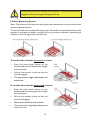
1
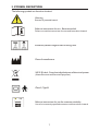
Freedom II
4 Section Profiling Bed
Instructions for use
www.sidhil.com
Freedom II
Electrically Operated Profiling Bed
Welcome to Sidhil
Still making it better...
At Sidhil, everything we do
is designed around quality.
From our modern and efficient
manufacturing plant in Halifax,
West Yorkshire, we manufacture
a range of products for the
healthcare market using leading
edge production technology and
finishing processes.
We are the only remaining
volume manufacturer of
hospital beds in the UK,
bringing together innovation
in product development,
sales, customer service and
logistics to provide clear
benefits for our customers
in terms of flexibility, short
production timescales and
support for our nationwide
network of service and
maintenance centres.
Excellence in customer
service is our key objective.
Alongside our focus on
innovation, research and
product development, we
use our UK manufacturing
facility to ensure optimum
levels of product and
spares availability,
with unparalleled
levels of reliability and
performance.
Corporate social responsibility
is also an issue for Sidhil. We
have now received accreditation
to ISO 14001, underlining our
commitment to maintaining the
highest levels of environmental
awareness and sustainability
across our manufacturing
operation.
3
CONTENTS
1. INTRODUCTION .............................................................................. 5
1.1 Features .............................................................................................. 5
1.2 Warnings and Cautions ........................................................................ 5
2. USE..................................................................................................... 6
2.1 Typical Use .......................................................................................... 6
2.2 Risk Assessment ................................................................................. .6
2.3 Bed Load ............................................................................................. 6
2.4 General Warning ................................................................................. 6
3. SYMBOL DEFINITION ...................................................................... 7
4. PARTS IDENTIFICATION ................................................................. 8
5. BED ASSEMBLY AND PREPARING FOR USE ................................... 9
5.1 Removal From the Transport Stand ...................................................... 9
5.2 Assembling the Bed ..............................................................................10
5.3 Fitting the Electrical System ..................................................................11
5.4 Fitting the Side Rails .............................................................................12
5.5 Checking the Bed ................................................................................ 14
6. OPERATION OF THE BED ................................................................ 15
6.1 General Safety ..................................................................................... 15
6.2 Preparing For Use................................................................................ 15
6.3 Brake System ...................................................................................... 16
6.4 Side Rails ............................................................................................. 16
6.4.1 Mattress Thickness................................................................ 16
6.4.2 Operating the Side Rails.............................................................. 17
6.5 Electrical Operation ............................................................................ 18
6.5.1 Handset Functions .................................................................18
6.5.2 Lockout Functions .................................................................18
6.6 Knee Break / Leg Section ..................................................................... 19
7. ASSEMBLY ONTO THE TRANSPORT STAND ................................. 20
8. POWER FAILURES ............................................................................. 22
9. DECONTAMINATION ....................................................................... 23
9.1 Cleaning and Disinfection Guidelines .................................................... 23
9.2 Steam cleaning ..................................................................................... 24
10. MAINTENANCE .............................................................................. 25
10.1 Fault Finding ....................................................................................... 26
10.2 General Maintenance ......................................................................... 27
11. SPECIFICATION .............................................................................. 28
11.1 Bed Data ............................................................................................ 28
11.2 Electrical Data .................................................................................... 29
12. WARRANTY ..................................................................................... 30
4
1. INTRODUCTION
Thank you for purchasing this product. These instructions for use should be read
carefully before operating the bed. Please ensure that you understand all instructions,
if you have any questions concerning the operation or maintenance of the bed please
contact your provider / supplier who will provide you with expert professional advice.
1.1 Features
• Electrically operated backrest, height and knee break angle
• Infinitely variable electrically operated foot down tilt (Trendelenburg & reverse Trendelenburg)
• Auto contour – simultaneous adjustment of the backrest and knee break
• Patient handset with integral function lockout
• Bed breaks down into four separate sections
• Integral full length side rails
• Transport stand to aid storage and bed transportation
1.2 Warnings and Cautions
Warnings in these instructions for use highlight potential hazards that if
disregarded could lead to injury or death.
Warning
Cautions in these instructions for use highlight potential hazards that if
disregarded could lead to equipment damage or failure.
5
2. USE
2.1 Typical Use
Your bed is intended for use within the home environment. It has been designed
to provide users with optimum independence and freedom of movement through
the use of a touch button handset. The bed offers greatly reduced manual handling
requirements for the carer by providing a bed with a fully profiling platform and
electrical height adjustment capability.
2.2 Risk Assessment
Before a patient uses the bed a risk assessment must be performed on a patient by
patient basis. The risk assessment should include but is not limited to:
• Entrapment
• Falling out of the bed
• Small children (and adults)
• Patients with learning difficulties
• Unauthorised people
Bed functions must be locked out if there is any doubt about the ability
of the patient to operate the bed safely.
Warning
2.3 Bed Load
213kgs (33 stone)
178kgs (28 stone)
The safe working load of the bed is: The maximum user weight of the bed is: 2.4 General Warning
• Misused electrical equipment can be hazardous.
• Accessories that have not been approved or designed for use with the bed should not be used.
Warning
• Electrically operated beds should not be used in the presence of flammable gasses.
6
3. SYMBOL DEFINITION
The following symbols are found on this bed:
Warning
Beware of potential hazard
Refer to instructions for use - Recommended
Failure to read the instructions for use could introduce a hazard
Maximum patient weight & Safe working load
Place of manufacture
W.E.E.E Label - Found on individual parts of electrical system
(Waste Electrical and Electrical Equipment)
Class II, Type B
Refer to instructions for use for mattress suitability
Use of an incorrectly specified mattress could introduce a hazard
7
4. PARTS IDENTIFICATION
1. Head/foot end
2. Castor
3. Handset
4. Lockout fob
5. Control box & knee break actuator
6. Leg section
7. Locking collar
8. Hi/low actuator
9. Side rail
10. Backrest actuator
11. Backrest
(Transport stand not shown)
8
5. BED ASSEMBLY AND PREPARING FOR USE
• Before attempting to assemble the bed ensure these instructions have been read and fully understood.
• It is advisable to assemble the bed with a second able bodied person.
Warning
• Take care when disassembling the bed from the transport stand, the sections are of considerable weight.
5.1 Removal From the Transport Stand
No tools are necessary for the assembly of the bed. The assembly procedure is as
follows:
• Clear the area intended for the bed of any obstructions and ensure the surface is level.
• Apply the brakes to the castors.
•
Loosen the hand wheels on the transport stand that hold the leg section in place and then lift this section off the stand and carefully place flat on the floor.
• Loosen the hand wheels on the backrest section (attaching it to the transport stand) and then lift this section off the stand
and carefully place flat on the floor.
• Turn the locking collars on one of the bed ends so that they are both in the unlocked position.
• Carefully lift the ends of the transport stand away from the bed end and place
carefully against a wall or on the floor. Note: when the transport stands are lifted away neither bed end will be supported.
• Turn the locking collars on the remaining bed end so that they are in the unlocked position.
• Carefully lift the ends of the transport stand away from this bed end.
The bed has now been separated into its constituent parts.
9
Collar
unlocked
5.2 Assembling the Bed
•
Whilst supporting one of the bed ends lift one of the mattress platform halves and hook into the bed end. Turn the locking collars into their locked position. Note: If this action is being undertaken by a single person Sidhil recommend that the castors are braked before assembly commences.
• Repeat for the remaining bed end and mattress platform halve.
Collar
locked
• Release the brakes on the castors.
• Bring both halves of the bed together and align each section so that the spigots in the head end locate into the open tube ends in the foot end. Pull the two sections together and tighten the 2 hand wheels.
Spigot
• The bed must never be used with the hand wheels loose or if missing.
Warning
• The bed must never be used with the locking collars in the unlocked position or if missing.
If the bed has been supplied with tie wraps/Velcro (or similar) securing
any of the sections in place ensure they are removed prior to operation.
Caution
10
5.3 Fitting the Electrical System
•
Plug the actuator and handset cables into the control box. The cables are colour matched to the graphic on the control box so using this, plug the cables into the corresponding ports. Note, the plugs only fit into the ports in one orientation. Ensure the cables are plugged fully into the control box.
Note: The two bed ends are identical but plugging them into the correct port is important. Note the cable tie colour before plugging in.
• Once all the cables are connected they are to be secured in place by attaching the supplied anti-removal clip.
• Clip the mains cable into the hook on the head end section of the bed.
Mains Cable Clip
Hi/Low - Head
End
Hi/Low - Foot
End
Backrest
Knee Break
Handset
• Ensure all cables are free from moving parts and are not under excessive tension.
Caution
• Ensure the two hi/low actuators are plugged into the correct ports, if not the tilt function will not work correctly.
11
5.4 Fitting the Side Rails
• Raise the bed to approximately the midpoint of its height range (see page 18 for operation of the handset).
• Lower the finger assemblies to their ‘down’ position. (see page 17 for an explanation of how to lower the fingers).
• Remove the hand-wheel from the side rail channel at the foot end of the bed.
• Remove the entire finger assembly set from the channel (as per top right image).
•
Taking the first side rail slide the end of it into the top set of fingers that are still located in the channel at the head end of the bed. Carefully rest the unattached end on the floor taking care to ensure that the other end is sufficiently far into the fingers so that it will not fall out.
• Take the previously removed assembly and clip the wire into the top moulding (the top moulding is identified by the metal release catch in the middle). Ensure the open end of the wire loop is pointing towards the end of the moulding with the half moon in it.
• Slide the fingers into the side rail.
• Whilst holding the fingers in the side rail, with the other hand slide the plastic slider stop into the channel. Slide the plastic finger assembly into the channel (after the slider stop). Lift the assembly until a click is heard and the mechanism locks into place, approximately one third up the channel. Let go of the side rail.
12
• Take the second side rail and fit this into the
remaining lower set of fingers that are still
located in the channel at the head end of the
bed. Carefully rest the unattached end on
the floor taking care to ensure that the other
end is sufficiently far into the fingers so that
it will not fall out.
• Take the remaining finger assembly and
position the top finger through the wire
loop, so that the bottom finger is hanging
freely under the loop. (Note, if there is no
wire loop visible push it down the channel
using the slider stop).
• Lift the remaining side rail and slide the
fingers into the open end, ensuring that one
finger remains within the wire loop.
• Whilst holding the fingers in the side rail,
with the other hand slide the plastic spacer
block into the channel.
•
Slide the finger assembly partially into the
channel. Clip the open end of the wire loop
into the groove that is positioned just above
the lower finger. Once clipped into place lift
the complete side rail assembly to the top of
the channel.
• Re-fit the previously removed hand-wheel.
(The hand-wheel is orientated so that
when fitted the threaded section is pointing
towards the middle of the bed.)
• Repeat the assembly process for the side rail
on the other side of the bed.
If there is any doubt about the assembly of the side rails contact the
provider of the equipment, incorrectly fitted side rails can lead to death.
Warning
13
5.5 Checking the Bed
The bed is now fully assembled. Before the bed is put into use ensure the bed is
correctly assembled:
• Are the locking collars on the corners of the bed correctly orientated in the locked position?
• Are the 2 mattress platforms and 4 side rail channel hand wheels tight?
• Has all packaging been removed e.g. cable ties/Velcro securing the platform sections?
• Are the cables free of all moving parts of the bed and is there sufficient slack in the cables to allow for movement?
• Is the bed clear of obstructions?
• Has a risk assessment been performed on the suitability of the bed for the user?
14
6. OPERATION OF THE BED
6.1 General Safety
• When the bed is operated, ensure that obstacles such as over bed tables and other furniture are not causing an obstruction.
• Ensure the electrical cables are not in tension.
• Ensure that any mattresses used are of the correct size and type and have been fitted correctly. A range of suitable pressure relieving and pressure reducing mattresses are available from Sidhil Ltd.
• Before operating the bed ensure the patient is positioned appropriately.
• When a patient is left unattended ensure the bed is set at its minimum height.
Special care should be taken when fitting an air mattress to the bed as
incorrect fitting could damage the bed frame.
Caution
6.2 Preparing For Use
Prior to operating the bed for the first time the following simple checks must be
performed:
• Ensure the bed and all accessories are at room temperature.
• Ensure the bed has been cleaned and disinfected (page 23).
• Ensure the mains cable is plugged into an appropriate mains socket.
• Ensure the brakes on the castors at the head end of the bed have been applied.
• Using the handset ensure the bed is level (see page 18 for handset operation).
Note: if the electrical functions do not operate ensure the handset has been ‘unlocked’
(see page 18 for handset operation).
15
6.3 Brake System
The bed has 4 braked castors.
• To apply the brakes: Press the brake pedal down.
• To release the brakes: Lift the brake pedal up.
When the bed is in use ensure the brakes on the castors at the head end of the bed have
been applied.
• If the bed is to be pushed up/down a slope it is advised that two people
move the bed, with one person at each end.
Warning
• If the bed is to be pushed with a heavy load it should be assessed
whether or not two people should move the bed, this is dependent on
the situation and load on the bed.
6.4 Side Rails
The bed comes as standard with full length side rails. A side rail height extension can
be ordered as an accessory.
When specifying a mattress and side rail combination a clinical assessment of the
patient’s needs must be carried out in line with the local policy.
6.4.1 Mattress Thickness
• Full length side rails = 158mm maximum mattress thickness.
•
Warning
Full length side rails with height extension = 270mm maximum
mattress thickness.
• Side rails must only be used with a mattress of the correct size and type
that is approved for use with this bed.
If an overlay air mattress is used it may be necessary to use a thinner foam mattress for
the combined height to maintain the 270mm dimension.
Refer to MHRA Device Bulletin DB2006 (06) ‘Safe use of bed rails’.
Side rails pose a potential entrapment hazard, please refer to side rail safety
notice, SR/PSN 01/01/1, supplied with this product.
16
6.4.2 Operating the Side Rails
• Ensure the side rails are locked in place at all times when in the raised
position.
• A risk assessment should be carried out to consider the age, condition
and size of the patient to assess the suitability of side rails.
Warning
• Side rails are not designed to act as restraints for patients.
• Side rails are not designed to be used as a patient lifting aid.
• When operating the side rails ensure they are free from obstructions,
to prevent injury/entrapment.
• Do not use the side rails to move the bed.
Caution
• When lowering do not drop the side rail.
To lower:
1. Lift the side rail vertically upwards.
2. Depress the release catch.
3. Gently lower the side rail (the release catch can be let go of when lowering the side rail).
To Raise:
1. Lift the side rail until it is heard to latch into position at the top height.
17
6.5 Electrical Operation
The bed is supplied with an easy to use handset, the handset can either be operated
by the occupant or carer. If the carer is to operate the bed ensure that the occupant is
made aware of the action(s) about to take place.
Ensure a risk assessment is undertaken to ensure the suitability of the
occupant using the handset.
Warning
6.5.1 Handset Functions
6.5.2 Lockout Function
The handset is supplied with a lockout function which enables the carer to disable the
handset if it is deemed unsuitable for the occupant.
To lock/unlock the handset, swipe the fob over the padlock symbol.
The handset is likely to be in the locked state when the bed is first installed.
18
The bed is not fitted with a battery backup facility. The bed must always be
plugged into the mains supply during normal use.
Warning
6.6 Knee Break/Leg Section
Note: The operation of the knee break/leg section is dependent on the position of the
ratchet as detailed below.
The bed is fitted with an adjustable leg section. When the knee break function on the
handset is operated the height or angle of the leg section is adjusted, depending on
whether or not the leg section ratchet is set.
To set the bed so that the leg section is raised:
• Press the knee break button on the
handset and raise the knee break (height
not important).
• Lift the foot section a little so that the
ratchet engages.
• The leg section height adjustment will
now be set.
To set the bed so that the knee break is raised:
• Press the knee break button on the
handset and raise the leg section (height
not important).
• Lift the foot section a little so that the
ratchet disengages
• Gently lower the foot section down.
• The knee break height/angle adjustment
will now be set.
19
7. ASSEMBLY ONTO THE TRANSPORT STAND
• Before attempting to assemble the bed onto the transport stand ensure these instructions have been read and fully understood.
• It is advisable to assemble the bed with a second able bodied person.
Warning
• Take care when assembling the bed onto the transport stand, the sections are of considerable weight.
Electrics
• Flatten and lower the bed to its minimum height (see page 18 for operation of the
handset).
• Unplug the mains cable from the mains socket.
• Using a flat bladed screwdriver remove the anti-removal clip from the control
box.
• Unplug the hi / low and knee break actuator cables from the control box (see page
11).
Bed Frame
• Release the brakes from the castors.
• Loosen the hand wheels in the middle of the bed frame.
• Whilst supporting both halves of the bed frame split the bed in half and gently
lower onto the floor.
• Unlock both locking collars on one end.
• Whilst supporting the bed end lift the platform half away and gently position both
sections on the floor / against a wall.
• Repeat for the remaining half of the bed.
• Using the 2 orange Velcro straps that first came with the bed, secure the moving
parts of the backrest and leg section to the bed frame halves.
Side Rails
• Raise/lower the bed to approximately its mid height (see page 18 for operation of
the handset).
• Remove the hand-wheel from one of the channels.
• Lower the side rail to its bottom position (the lower slider will partially protrude
from the channel).
• Whilst holding the lower side rail unclip the wire from the lower finger assembly
and carefully slide out of the channel.
20
• Carefully remove the lower side rail.
• Whilst holding the upper side rail press the release catch and carefully slide the
upper finger assembly out of the channel.
• Carefully remove the upper side rail.
• Relocate the finger assemblies into the channel (see page 12 for assembly order).
• Refit the hand-wheel into the channel.
• Repeat for the other side of the bed.
Assembling onto the Transport Stand
• Position both transport stand brackets onto one bed end, taking care to ensure
the brackets are both orientated in the correct direction.
• Turn both locking collars into the locked position.
• Hook the remaining bed end onto the transport stands.
• Lock the castors.
• Carefully lift the backrest section and lower the spigots through the open tubes on
the side of the transport stand brackets, ensuring the electrics are facing inwards.
• Tighten the hand wheels on the transport stand.
• Carefully lift the leg section and lower the open end onto the vertical bars, ensuring
the electrics are facing inwards.
• Tighten the hand wheels on the leg section frame.
• Ensure all cabling is neatly wrapped around the relevant bed sections and is not
dragging on the floor or is under excess tension.
The bed must never be moved on the transport stand with the locking
collars in the unlocked position or missing.
Warning
21
8. POWER FAILURES
The bed does not have battery backup functionality. In the event of a power failure
the bed will not function, resulting in the backrest and/or knee break remaining up, if
previously raised.
The backrest and knee break are operated via two individual actuators that are located
underneath the mattress platform.
• If either the backrest or knee break is raised, locate the actuator supporting the
relevant section.
• Hold / support the section.
• Remove the pins that hold the actuator in place.
• Gently lower the section(s) to the flattened position.
• It is recommended that 2 carers support the section prior to removing the pin.
Warning
• When the pins are removed there is nothing supporting the section, the carer(s) holding the frame must be ready to support the weight on removal of the pin.
22
9. DECONTAMINATION
9.1 Cleaning and Disinfection Guidelines
Infection control and routine cleaning must be carried out in accordance with your
local Infection control policy or regulatory body.
• Always disconnect the bed from the main power supply prior to cleaning.
• Ensure all ports on the electrical system (control box and actuators) have cable plugs inserted to maintain the IP rating.
Warning
• Regular cleaning and disinfection of the bed frame and relevant accessories will help to prevent the risk of infection to the occupant and / or carer.
• Prior to transferring the bed frame / accessory to another user ensure it has been cleaned and disinfected using the method as detailed below to help prevent the risk of cross infection.
It is advisable to remove any accessories that are fastened to the bed.
These instructions apply to all accessories apart from soft products (e.g. mattresses).
• All surfaces to be wiped down with a disposable soft cloth moistened with a mild
detergent and diluted in warm water (40°C).
• The bed should be cleaned by starting with the cleanest parts of the bed and
systematically moving to the dirtiest parts. Extra care should be taken around
areas where excess dirt or dust may gather.
• The cloth should be changed during the cleaning process if it becomes soiled.
• Rinse down with clean water to remove detergent residue.
• Wipe surfaces down with 1,000 parts per million chlorine solution (0.1%).
• Dry off with a paper towel.
• Always ensure the cleaned parts are allowed to dry before putting the mattress
back in place.
Note: If any of the 3 stages stated above (detergent, rinse down & chlorine solution)
are omitted or combined it will reduce the effectiveness of the clean.
In cases of blood spills or other bodily fluids it is recommended that a chlorine solution
of 10,000 parts per million (1%) is used instead. Ensure fabric surfaces are rinsed with
clean water after application.
Note: The use of neat bleach or similar surface cleaners is not recommended as
damage may be caused to the cleaned surfaces.
23
Alternatively:
Sidhil recommend the use of Tristel ‘Fuse’ sachets and Tristel ‘Jet’ gel. Follow the
product documentation for concentration guidelines and instructions for use.
Tristel Codes:
NHS Supply Chain Codes:
FUS/SUR/FRA (Fragranced) 1 x 40 sachets FAL649 (Fuse for Surfaces Fragranced) FUS/SUR/UNF (Unfragranced) 1 x 40 sachets
FAL650 (Fuse for Surfaces Unfragranced)
JET/head 1 x JET Trigger Head
FAL688 1 x Jet Trigger Head
JET/PACK/FRAG 1 x refill pack fragranced
FAL696 1 x refill pack fragranced
JET/PACK/UNF 1x refill pack unfragranced
FAL697 1 x refill pack unfragranced
Sidhil also recommend the use of Chlor-clean tablets. Follow the product documentation instructions for concentration guidelines and instructions for use.
Refer to the Sidhil infection control policy, copies are available from Sidhil Ltd. Contact
details can be found on the back of this booklet.
9.2 Steam Cleaning
The Freedom II bed can be dry steam cleaned. The individual manufacturer’s instructions should be followed when using a steam cleaner and the following
precautions observed:
• Avoid directing steam directly at electrical components and reduce steam pressure when cleaning near electrical items and connections.
• Use soft brushes and wiper cloths as recommended by the steam cleaner manufacturer.
• Do not use high pressure hoses on the bed as they could cause damage to the
electrical components.
• Do not use excessive force or steam pressure on labels.
• Ensure the bed is dry and all debris from the cleaning process has been removed prior to reuse.
• Ensure all electrical functions operate as normal once the bed has been cleaned and dried.
Always disconnect the bed from the main power supply prior to cleaning.
Warning
24
10. MAINTENANCE
Only authorised service personnel or Sidhil service engineers should carry out repairs
or service activities. Failure to do so may result in the manufacturer’s warranty
becoming void. The bed must be serviced once yearly, as a minimum. Sidhil also
recommends that the carer performs frequent visual and operational inspections. If
there are any signs of damage or the bed is not performing as it should withdraw it from
service until the bed has been repaired and is fit for use again.
Periodically check to ensure that:
•
The bed operates as per its intended purpose.
•
All parts are present.
•
All fixtures and fittings are tight.
•
The frame is mechanically sound, with no cracking round welds.
•
No parts show signs of excessive wear.
•
The bed is cleaned following the guidelines in these instructions for use.
Disposal of components must comply with local policy.
• Always disconnect the bed from the main power supply prior to performing any maintenance procedures.
• No modification of this equipment is allowed.
Warning
• The bed should be vacated by the patient before any maintenance or inspection takes place. If this is not possible due to the patient’s mobility care should be taken for the service engineer not to make contact with the patient when working on electrical items.
• Only Sidhil approved components, specified for the Freedom II bed, should be used - if in doubt contact Sidhil Ltd or your local distributor.
• The mains cable is only to be replaced by authorised service personnel or a Sidhil service engineer.
25
10.1 Fault Finding
Listed below are a set of electrical faults that may occur within the service life of the
bed. If a fault does occur please try the following suggestions, as these may help in
diagnosing the fault.
Fault
Electrical function(s)
do not work
Electrical function
working slowly
Possible Cause
Remedy
Functions locked out on handset
Unlock function(s)
Mains lead not plugged into the control
box or wall
Check to see if the ‘power on’ light on
the control box is lit and the mains lead is
plugged in at both ends
Fuse has blown in the mains plug
Check to see if the ‘power on’ light on
the control box is lit, if not replace fuse
Actuator / handset leads not plugged in
Check plug connections on the control
box and actuators
Damage to mains cable, actuator cable
or handset cables
Turn off at the mains and contact an
approved service engineer
Heavy load on the bed and the duty cycle
has been exceeded
Remove load and allow control box to
cool before re-operating
Heavy load on the bed
Remove load
26
10.2 General Maintenance
Sidhil recommend that the following maintenance procedure is performed every 12
months.
Always disconnect the bed from the main power supply prior to
performing any maintenance procedures.
Warning
• Check that all electrical functions operate correctly on the handset.
• Check that all electrical cables are in good condition.
• Check that the mains cable and plug are in good condition, if either is damaged it
must be replaced as a complete assembly, the plug must never be rewired.
• Check that all nuts, bolts and fasteners are tight and that none are missing or
incomplete.
• Check that all locking collars and hand wheels are present.
• Check that both the knee break and leg rest functions work correctly.
• Check the castors lock / unlock correctly and that when locked the castors do not
swivel or roll.
• Check that the frame is mechanically sound with no cracking at welds etc.
• Check that the lock on the safety sides automatically engages when raised.
Refer to the service manual for part codes and assembly detail. Copies are available
from Sidhil Ltd.
27
11. SPECIFICATION
11.1 Bed Data
Overall length
2230mm
Overall width
980mm
Mattress platform height 335mm – 735mm (+/-10mm)
Under bed clearance (to underside of frame) 295mm (+/-10mm)
Under bed clearance (to underside of actuator) 145mm (+/-10mm)
Mattress platform length
2010mm
Mattress platform width
870mm
Foot down tilt Mattress platform angles (max)
0 - 11°
75°
27°
23°
Safe working load
Maximum patient weight
213kgs (33 stone)
178kgs (28 stone)
Product weight:
(Bed on transport stand): 75kgs
(Side rails)
14.5kgs
Mattress sizes:
Length
Width Thickness
2000mm - maximum
864mm - recommended (880mm - maximum)
See page 16
28
11.2 Electrical Data
Voltage in:
100-240V, ~50/60Hz.
Current in:
Max. 3,15A
Duty cycle*
10%
2 mins of continuous use followed by 18 mins not in use.
*Electrically operated beds are intended to be operated intermittently rather than continuously. If the bed is operated
continuously for up to 2 minutes it must then be left for at least 18 minutes before re-use to allow the electrical system to cool
sufficiently. If the bed is continuously used for an extended period of time and it exceeds the duty cycle the control
box may become temporarily disabled or irreparably damaged.
Safety standards
BS EN 60601-1:2006
BS EN 60601-2-52:2010
EMCBS EN 60601-1-2:2002
Electrical shock prevention:
Liquid ingress protection
IP54
The electrical system is only suitable for use when:
Ambient temperature
+5° to +40°C
Humidity
20% - 90% at 30°C
29
12. WARRANTY
Sidhil Ltd guarantees this product is free from defects in material and workmanship under normal use
for 1 year (full parts and labour) from the date of purchase from Sidhil Ltd, its subsidiary companies,
authorised dealers and international distributors. Proof of purchase must be presented with any claim.
Except as provided herein, Sidhil Ltd, product warranty does not cover damage caused by misuse or abuse,
accident, the attachment of any unauthorised accessory, alteration to the product, or any other conditions
whatsoever that are beyond the control of Sidhil Ltd. Sidhil Ltd, its subsidiary companies, authorised dealers
and international distributors shall have no liability or responsibility to customers or any other person or
entity with respect to any liability, loss or damage caused directly or indirectly by use or performance of the
product or arising out of any breach of this warranty, including but not limited to any damages resulting from
inconvenience, loss of time, property, revenue, or profit or any indirect, special, incidental or consequential
damages, even if Sidhil Ltd, its subsidiary companies, authorised dealers or international distributors have
been advised of the possibility of such damages.
In the event of a product defect during the warranty period you should contact your supplier, whether it
be Sidhil Ltd, its subsidiary companies, authorised dealers or international distributors who will at their
option unless otherwise provided by law; a) correct the defect by product repair without charge for parts
and labour b) replace the product with one of the same or similar design or c) refund the purchase price.
All replaced parts and products on which a refund is made become the property of Sidhil Ltd. New or
reconditioned parts and products may be used in the performance of the warranty service. Repaired or
replaced parts and products are warranted for the remainder of the original warranty period. You will be
charged for repair or replacement of the product made after the expiration of the warranty period.
This warranty does not cover; a) damage or failure by or attributes to acts of God, abuse, accident, misuse,
improper or abnormal usage, failure to follow instructions, improper installation or maintenance, alterations,
lightning or other incidence of excess voltage or current, b) any repairs other than those provided by a Sidhil
Ltd authorised technician, c) consumables such as fuses, d) cosmetic damage, e) transportation, shipping
or insurance costs or f) costs of product removal, installation setup service adjustment or re-installation.
This limited 1 year warranty gives you specific legal rights and you may also have other rights.
Sidhil Ltd cannot be held responsible for any injury or incident which relates to the use of this bed in
conjunction with accessories manufactured by companies other than Sidhil Ltd.
All products carry the CE mark in accordance with EC Directive on Medical Devices (93/42/EEC).
Sidhil has a policy of continual product improvement and reserves the right to amend specifications covered
in this document.
No part of this document may be reproduced without the written approval of Sidhil Ltd.
30
NOTES
31
CONTACT INFORMATION
Tel: +44 (0) 01422 233000 Fax: +44 (0) 01422 233010
Email: [email protected] www.sidhil.com
Sidhil Business Park, Holmfield, Halifax, HX2 9TN
A member of the Siddall & Hilton Ltd. Group of Companies
(93/42/EEC)
Certificate No. FM14550
INSTRUC/BED01, 19/06/2014 - Rev.3