1
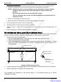
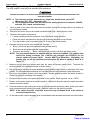
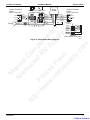
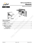
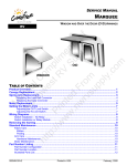
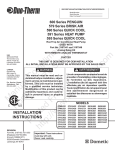
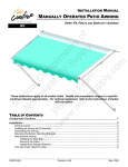
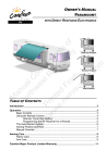
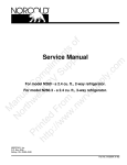
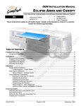
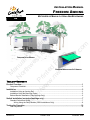
INSTALLATION MANUAL FREEDOM AWNING MOTORIZED OR MANUAL LATERAL ARM BOX AWNING M an N u or al th C ht w om es tp pl :// P t R im w rin V e w te n w S .n d F up ts w r o p rv om ly f su pp ly .c om RV FREEDOM PATIO AWNING FREEDOM WINDOW AND OTD AWNING TABLE OF CONTENTS Product Overview .......................................................................................................................... 1 Component Checklist..............................................................................................................................2 Installation ..................................................................................................................................... 3 Installation Using an Awning Rail ...........................................................................................................3 Installation Using the Mounting Plates....................................................................................................5 Bottom Bracket Installation (Patio Awnings Only) ..................................................................................6 Switch Installation (motorized awnings only)............................................................................. 7 Standard Switch and Wiring ...................................................................................................................7 Wiring Using the Relay Module (OEM Installations Only) ..............................................................8 Testing the Operation ................................................................................................................. 10 Pitch Adjustment...................................................................................................................................10 052978-021 Printed in USA November, 2008 PROPRIETARY STATEMENT The Freedom Awning is a product of Carefree of Colorado, located in Broomfield, Colorado, USA. The information contained in or disclosed in this document is considered proprietary to Carefree of Colorado. Every effort has been made to ensure that the information presented in the document is accurate and complete. However, Carefree of Colorado assumes no liability for errors or for any damages that result from the use of this document. M an N u or al th C ht w om es tp pl :// P t R im w rin V e w te n w S .n d F up ts w r o p rv om ly f su pp ly .c om The information contained in this manual pertains to the current configuration of the models listed on the title page. Earlier model configurations may differ from the information given. Carefree of Colorado reserves the right to cancel, change, alter or add any parts and assemblies, described in this manual, without prior notice. Carefree of Colorado agrees to allow the reproduction of this document for use with Carefree of Colorado products only. Any other reproduction or translation of this document in whole or part is strictly prohibited without prior written approval from Carefree of Colorado. SAFETY INFORMATION WARNING A WARNING INDICATES A POTENTIALLY HAZARDOUS SITUATION WHICH, IF NOT AVOIDED, COULD RESULT IN DEATH OR SERIOUS INJURY AND/OR MAJOR PROPERTY DAMAGE. CAUTION A CAUTION INDICATES A POTENTIALLY HAZARDOUS SITUATION THAT MAY CAUSE MINOR TO MODERATE PERSONAL INJURY AND/OR PROPERTY DAMAGE. IT MAY ALSO BE USED TO ALERT AGAINST UNSAFE PRACTICES. NOTE: A note indicates further information about a product, part, or step. Tip: A tip provides helpful suggestions. Safety Notes: • • • • Always disconnect battery or power source before working on or around the electrical system. Always wear appropriate safety equipment (i.e. goggles). Always use appropriate lifting devices and/or helpers when lifting or holding heavy objects. When using fasteners, use care to not over tighten. Soft materials such as fiberglass and aluminum can be "stripped out" and lose the ability to grip and hold. Reference Publications located @ www.carefreeofcolorado.com:' xxxxxx-xxx Installation Manual xxxxxx-xxx Owner's Manual xxxxxx-xxx Service Manual Carefree of Colorado a Scott Fetzer company 2145 W. 6th Avenue Broomfield, CO 80020 303-469-3324 ♦ www.carefreeofcolorado.com Table of Contents Carefree of Colorado Installation Manual PRODUCT NAME PRODUCT OVERVIEW The Freedom Awnings are state of the art lateral arm awnings. When retracted, the housing provides protection against the elements while the streamlined styling blends in with the coach side wall. The full tension canopy fabric allows the awning to be partially or fully extended for best shade coverage. Each unit is equipped with lateral support arms. No vertical arms interfere with coach sidewalls, custom graphics or equipment that may be mounted on the sidewalls. M an N u or al th C ht w om es tp pl :// P t R im w rin V e w te n w S .n d F up ts w r o p rv om ly f su pp ly .c om Freedom Awning Specifications: • Fully retractable and self storing; • Available as manual or motorized; • The sealed awning motor operates on standard 12VDC (range 10VDC to 14VDC); • Case and frame are constructed of high-strength aluminum extrusions, protected with a polyester paint finish; • Stainless steel fasteners and hardware. WINDOW AND OTD AWNINGS Available Widths: OtD 50" 54" 60" 66" 72" 8' 9' 10' 11' 12' 13' Window 50" 54" 60" 66" 72" 7' 36" Extension: PATIO AWNINGS 8' 9' 10' 11' 12' 13' 14' 15' 16' Available Widths: Manual 8' 9' 10' 11' 12' 13' Motorized 6' 1" 6' 6" 8' Extension: LEADING EDGE POSITION ACTUATION AND CONTROL Lateral Arm Spring Power: Minimum Tension Open Roll Out/In Controlled by Electrical Motor Position Control: Motorized: Roll Out/In Controlled by Manual Crank Manual: MOTOR SPECIFICATIONS Tubular Motor Type: 12VDC Minimum: 8VDC Output: 30 Watts Power: Nominal Current: 2.5Amps Max Current: 14Amps (stall @ min voltage) Motor and controls are routed and hardwired into the vehicle’s 12V system Power Source: Continuous: 6Nm/4.5 ft-lbs. Tightening: 18Nm/13.2 ft-lbs. Torque 15 rpm Speed COLORS AVAILABLE Standard: Polar White Case Custom: Black, Champagne and Pewter Wooven Acrylic Fabric, vinyl (refer to sales literature for colors available) Fabric:1 Note: 1.The motorized patio awning is only available in vinyl. 2” (approx) Awning Width Fabric Width Motorized 3 1/2” 2.5” (approx) 7.2” Awning Width Fabric Width Manual 2” (approx) 5 5/8” 2” (approx) 5 5/8” FIII001b Figure 1. General Dimensions 052978-021 1 Table of Contents PRODUCT NAME Installation Manual Carefree of Colorado COMPONENT CHECKLIST 6 5 3 7 8 9 10 12 4 11 2 17 14 15 16 M an N u or al th C ht w om es tp pl :// P t R im w rin V e w te n w S .n d F up ts w r o p rv om ly f su pp ly .c om 13 1 18 19 20 21 22 FIII013a Figure 2. Component Checklist. ; ITEM DESCRIPTION QTY NOTE 1 Awning Assembly 1 1 2 Awning Rail 1 HARDWARE KITS (application depending on Awning Length, see note 2) A B C 2 3 Mounting Plate 1 1/2" 1 1 2 4 Mounting Plate 3" 2 - 5 Mounting Plate 18" - 2 2 6 Screw, Hex Head #10 x 3/4 20 20 20 7 Screw, Lag 1/4 x 1 1/2 8 12 13 8 Carriage Screw 1/4-28 x 2 5 5 6 9 Nut 1/4-28 7 7 8 10 Lock Washer 1/4 7 7 8 11 Fender Washer 1/4 7 7 8 12 Screw, Phillips Pan Head #6 x 3/8 5 5 6 13 Bottom Bracket 2 2 2 3 14 Screw, Flat Head #10 x 3/4 4 4 4 3 15 Moly Rivet 4 4 4 3 16 Screw, Flat Head M4 x 25mm 4 4 4 17 Owner's Manual 1 1 1 6 18 Crank Handle, "Hook" 1 1 1 4 ELECTRICAL 19 Switch, DPDT, Momentary Contact 1 5 20 Switch Plate, Single Switch 1 5 21 Screw #6 x 1/2 4 5 22 Spade Connector, Female 4 5 Notes: 1. Specific awning configuration is specified at time of order, including awning length, fabric, color etc. Check awning assembly against original purchase order. 2. Hardware Kits are based on awning length: A = 9' or shorter 3. 4. 5. 6. 2 B = 10'-11' C = 12'-13' Bottom bracket (item 12) and attaching hardware (items 13 & 14) is used with patio awning only Crank Handle (item 19) used with manual crank version only. Items listed under "Electrical" are used with motorized version only Place the Owner's Manual (item 17) with RV owner information. Installation manual, if included is for installer reference. 052978-021 Table of Contents Carefree of Colorado Installation Manual PRODUCT NAME INSTALLATION Two methods are available to mount the Freedom awning. The awning may be mounted using an awning rail. When this is not practical, the awning may be mounted using a set of mounting brackets that mounts to the wall (refer to page 5). M an N u or al th C ht w om es tp pl :// P t R im w rin V e w te n w S .n d F up ts w r o p rv om ly f su pp ly .c om Prior to mounting the awning: • Review both mounting methods to determine the best mounting method for the particular application. The awning rail must be attached to structural components for stability. The awning rail can be mounted to a blind surface while the mounting brackets require access to the inside of the mounting surface. • If there is an awning rail installed, check that the awning rail runs the full length of the awning. The awning rail must be extremely straight to accommodate the awning mount. If a full length awning rail is installed, skip to step 6 under “Installation Using an Awning Rail”. • Ensure that the awning will not interfere with other equipment such as light fixtures, exhaust vents, openings, etc. INSTALLATION USING AN AWNING RAIL 1. Determine the optimum positioning of the awning. • The centerline of the awning fabric is offset from the centerline of the awning assembly. To align the center of the fabric, use the backplate of the awning assembly for measurements. • When installed, the bottom of the awning case is 5 1/4” from the centerline of the awning rail. The rail must be mounted a minimum of 7” above openings to avoid interference. • Measure rail position so that the awning is mounted parallel to the ground. NOTE: Two styles of awning rail are available with the Freedom awnings. When mounting the rail, the slot must be pointed down. 2. Mark the centerline position with a chalk line. 3. Coat the back of the rail with silicone sealant or putty tape. 4. Align the awning rail onto the wall and secure with #10 x 3/4 screws. Use all the attach holes and ensure that the rail is securely mounted to the structural frame. 5. Lightly spray the inside track of the awning rail with a silicone lubricant. 6. Using a minimum of two people, lift the awning up and tilt as shown. Mounting Rail Awning Rail Standard Inverted FIII029 Figure 3. Awning Rail Styles. 5 1/4" (ref) FIII002 Figure 4. Mount Using Awning Rail. 7. Hook the mounting rail into the awning rail and roll down. 8. Adjust the position of the awning horizontally as required. It may be necessary to lightly lift the awning so that it will slide in the awning rail. 052978-021 3 Table of Contents PRODUCT NAME 9. Installation Manual Carefree of Colorado For the motorized awning only: Lift the awning upward slightly. On the coach wall, mark the location of where the motor wires exit the awning case. • Measure and drill one 1/4” hole through the outer wall at the mark. • Adjust the location as required. Measure to avoid any interior framing, cabinets, electrical components etc. that could be damaged or interfere with the hole location. Ensure that the motor cables are accessible after routing in the next step. This is a preliminary step, the wire and switch installation are completed after the awning is secured. M an N u or al th C ht w om es tp pl :// P t R im w rin V e w te n w S .n d F up ts w r o p rv om ly f su pp ly .c om NOTES: • Route the motor wires through the hole and seal with silicone sealant. 10. Rotate the awning down. 11. Open the awning. NOTE: To open the motorized awning, momentarily connect the motor wires to a 9-18VDC drill battery or car battery. If the motor runs in the reverse direction, reverse the leads. 12. (Refer to figure 4) Drill three (3) 3/16” holes through the back of the case into the mounting surface and into the structure. Use care to not drill through the inner wall. Drill Area Arm Mount Drill Area Centered Between Arms Drill Area Arm Mount FIII016a Figure 5. Securing the Awning Case. 13. Drill out the 3/16” holes in the awning case to 5/16”. Do not allow the drill to extend into the wall. CAUTION THE SCREWS MUST BE LOCATED IN THE OPEN AREAS OF THE AWNING CASE AS SHOWN. THE ARMS CANNOT CLOSE COMPLETELY IF THE SCREW HEADS ARE UNDERNEATH. 14. Secure the awning using three (3) 1/4 x 1 1/2 lag screws. 15. For patio awnings go to "Bottom Bracket Installation" on page 6. 4 052978-021 Table of Contents Carefree of Colorado Installation Manual PRODUCT NAME INSTALLATION USING THE MOUNTING PLATES 1. Determine the optimum positioning of the awning. • The centerline of the awning fabric is offset from the centerline of the awning assembly. To align the center of the fabric, use the backplate of the awning assembly for measurements. • The bottom of the mounting plates should be above any openings or frames to avoid interference when the awning is installed. • Measure each end of the awning position from the ground so that the awning is mounted parallel to the ground. Back Plate Edge of Back Plate M an N u or al th C ht w om es tp pl :// P t R im w rin V e w te n w S .n d F up ts w r o p rv om ly f su pp ly .c om Edge of Back Plate B A 9 foot or less Awning B Edge of Back Plate Edge of Back Plate C A 10 - 11 foot Awning C Edge of Back Plate Edge of Back Plate C A A C 12 - 13 foot Awning Equal Spacing A = 1 1/2" B = 3" C = 15 3/4" FIII017a Figure 6. Mounting Plate Pattern. 2. 3. Mark the position with a chalk line. Determine the correct plate pattern then use the plates as a template and drill the appropriate mounting holes. Attach brackets. • For attaching into existing structure: Drill 3/16” hole(s) through wall and into structure. Attach the plate using the supplied 1/4 x 2 hex head lag screws. • For attaching to a hollow wall: Drill 5/16” hole(s) through the wall. Attach the plate using the supplied 1/4 x 2 carriage bolts, fender washers, lock washers and nuts. Back Plate 1/4-20 Nut Lock Washer Fender Washer 5/16 Holes thru Wall 1/4-20 Carriage Bolt Mounting Plate Mounting Plate #6 x 3/8 Screw FIII006 Figure 7. Mount Using Plates. 052978-021 5 Table of Contents PRODUCT NAME 4. • • Installation Manual Carefree of Colorado For motorized awnings only: Using the awning back plate, measure the location where the motor wires exit the awning case. Transfer the measurement to the coach wall using the mounting plates as reference. NOTES: Adjust the location as required. Measure to avoid any interior framing, cabinets, electrical components etc. that could be damaged or interfere with the hole location. Ensure that the motor wires are accessible after routing. M an N u or al th C ht w om es tp pl :// P t R im w rin V e w te n w S .n d F up ts w r o p rv om ly f su pp ly .c om This is a preliminary step, the wire and switch installation are completed after the awning is secured. • Drill a 1/4" hole through the outer coach wall. • Route the motor wires through the hole while lifting the awning into position. 5. Set the awning into the hooks of the mounting plates. 6. Adjust the position of the awning horizontally as required. 7. (Refer to Figure 7) Attach the mounting plates to the awning case using the self-tapping #6 x 3/8 screws. • For patio awnings go to "Bottom Bracket Installation" on page 6. BOTTOM BRACKET INSTALLATION (PATIO AWNINGS ONLY) The patio awning is equipped with vertical supports. These supports extend from the leading edge of the awning to a bracket mounted on the wall or may be used in a carport position on the ground. 1. Determine the location of the brackets: • Open the Awning approximately 6" or enough to see the support legs in the leading edge. • Mark the location of the pivot point of the legs. • At the marks made previously, measure down vertically and mark the location of the brackets. The ideal location is 30" to 38" below the bottom of the awning. The brackets will work up to a maximum of 50 " below the awning. Support Legs (ref) O 5/32” Pilot Hole Leg Pivot Bottom Bracket 30” - 38” (optimum) 50” (maximum) #10 x 3/4 Flat Head Screws or Moly Rivets Pivot Pivot FIII018a Figure 8. Wall Mounted Support Plate. 2. Center the brackets on the location marks and using the bracket as a template, drill two (2) 5/32” pilot holes. 3. Attach the plate with two (2) #10 x 3/4 flat head screws. This completes the installation of the manual awning. Installation" on page 7. 6 For motorized awnings go to "Switch 052978-021 Table of Contents Carefree of Colorado Installation Manual PRODUCT NAME SWITCH INSTALLATION (MOTORIZED AWNINGS ONLY) STANDARD SWITCH AND WIRING 1. Determine the location of the switch. • There is approximately 8’ of wire from the point of entry. • Location should provide the operator a view of the awning during operation. • The switch requires a 2 3/4” x 2 3/4” area on the mounting surface and a minimum clearance depth of 2 3/4” from the mounting surface. Wall M an N u or al th C ht w om es tp pl :// P t R im w rin V e w te n w S .n d F up ts w r o p rv om ly f su pp ly .c om O 2 1/4" Locking Tabs Blue 2 3/4" 2 3/4" (min.) (typ.) 6 5B 4 Front View of Switch Panel Brown Rear View of Switch Panel Carefree of Colorado Covered Terminals on Bottom 3 2B 1 Ground +12VDC FIII007 Figure 9. Switch Installation. WARNING TERMINALS 1 AND 4 ARE CAPPED WITH FULLY INSULATED CONNECTORS. THESE TERMINALS MUST REMAIN CAPPED AT ALL TIMES. 2. Using a 2 1/4” hole saw, cut a hole through the mounting surface. 3. Route the awning wires through the hole and terminate with spade connectors. CAUTION ALWAYS DISCONNECT THE BATTERY AND ELECTRICAL SOURCES BEFORE WORKING WITH THE ELECTRICAL WIRING. 4. Run a 14 gauge wire (never use less than 16 gauge) from the power distribution panel (auxiliary battery circuit) or equivalent. The circuit should be protected by a 15 amp fuse. 5. Run a wire to system ground. 6. Route the two new wires through the hole and terminate with spade connectors. 7. Push the switch into the face plate until the tabs on the switch “click” into place behind the face plate. Ensure that the switch and face plate are oriented as shown. 8. Attach the four wires to the switch as shown. 9. Restore vehicle power and test operation. 10. If the awning operates in a reverse to the switch plate markings: • Shut off power; • Reverse the red and black motor leads; • Restore power and test. 11. Push the wires and switch into the mounting hole and secure the plate using four (4) #6 x 1/2” screws. 052978-021 7 Table of Contents PRODUCT NAME Installation Manual Carefree of Colorado Wiring Using the Relay Module (OEM Installations Only) The relay module is used only with selected OEM installations. CAUTION ALWAYS DISCONNECT THE VEHICLE BATTERY AND ELECTRICAL SOURCES BEFORE WORKING WITH THE ELECTRICAL WIRING. M an N u or al th C ht w om es tp pl :// P t R im w rin V e w te n w S .n d F up ts w r o p rv om ly f su pp ly .c om NOTE: a) The switch(es) must be momentary on, single pole, double throw, center OFF (Momentary ON – OFF – Momentary ON). b) The recommended cable from the switch to the awning should be 2-conductor, 20AWG, stranded, PVC coated, unshielded wire. 1. Route a cable for the motor wires from the motor location through the carriage walls to the location of the switch/relay module. 2. Butt-splice the motor wires to the installer furnished cable wires. Match the wire colors. 3. Determine the location of the switch. • Location should provide the operator a view of the shade during operation. • Follow the switch manufacturer’s directions for preparing the switch mount location. • The relay module must be mounted within 16” or less of the switch location. 4. Separate the wires from the relay module into 3 groups: • Brown, yellow and gray with spade terminals (primary switch), • Black and red with spade terminals (power leads), • Connector bundle with: Brown, yellow and gray (switch), and Blue and White (motor). NOTE: The relay module harness is supplied with one connector installed. The installer must furnish the mating connector (p/n 1-480704) and terminals (p/n 350547-3) for the exterior switch and motor cables. Vendor: AMP/Tyco Electronics. Alternately, the installer may cut off the connector and butt-splice the wires as shown in Detail A of Figure 10. 5. Measure and cut away any excess cable from the motor and primary switch wires. Terminate the wires and install in the mating connector as shown below. 4. Run an 18 gauge wire from the power distribution panel (auxiliary battery circuit) or equivalent to the relay module. The circuit should be protected by a 5 amp fuse (the motor has a maximum 2 amp stall current). 5. Run a wire from chassis ground to the relay module. Suitable ground would be the vehicle chassis or conductive structure connected to the chassis. 6. Butt-splice the two wires to the power wire leads on the module. Black is ground, red is +12VDC. 7. Restore vehicle power and test the switch operation. Note which direction raises the shade and which direction lowers the shade. 8. Orient the switch so that pushing the switch up corresponds with raising the shade, pushing the switch down corresponds with lowering the shade. Install the switch into the mounting surface. NOTE: If the switch cannot be reoriented, reverse the top and bottom leads to the switch to reverse awning direction. 9. On the relay module, remove the paper cover on the adhesive foam and press the module onto a flat surface. 8 052978-021 Table of Contents Installation Manual Installer Furnished Switch SPDT Center OFF Retract Common Extend 6 6 5 2 2 4 1 1 Blue Brown 5 4 Installer Furnished Switch SPDT Center OFF Gray Brown Yellow Blue White Gray Yellow Brown Retract Common Extend +12VDC Red Butt Splice (5 plcs) M an N u or al th C ht w om es tp pl :// P t R im w rin V e w te n w S .n d F up ts w r o p rv om ly f su pp ly .c om Motor Relay Module Rear View of Connectors Shown Gray Yellow Brown PRODUCT NAME Black Carefree of Colorado A Gray Brown Yellow Gray Brown Yellow Blue Brown Blue White Detail A Alternate Wire Connection PV3007 Figure 10. Relay Module Wiring Diagram. 052978-021 9 Table of Contents PRODUCT NAME Installation Manual Carefree of Colorado TESTING THE OPERATION Open and close the awning several times. • If the lead rail does not close parallel with the case, refer to "Pitch Adjustment" below. For motorized awnings: The motor limit switches are preset at the factory for best operation of the awning. If the switches become out of adjustment during installation, SEVERE DAMAGE to the motor can result. When the arms are fully extended, confirm that the motor stops and the fabric should be tight. If the motor continues to run, the fabric will sag; or, if the motor quits before the arms are extended, it will be necessary to adjust the “OUT” limit switch. M an N u or al th C ht w om es tp pl :// P t R im w rin V e w te n w S .n d F up ts w r o p rv om ly f su pp ly .c om • • When the arms are fully retracted, confirm that the motor stops when the awning is fully retracted. If the motor continues to run; or, if the motor quits before the arms are fully retracted, it will be necessary to adjust the “IN” limit switch. For motor replacement and/or if limit adjustments are necessary, refer to 052985-103 "Freedom Tubular Motor Replacement" available on-line @ www.carefreeofcolorado.com PITCH ADJUSTMENT The Freedom series of awnings provides minor pitch adjustment. This adjustment is for fine-tuning the installation to align the lead rail with the case. CAUTION WHEN THE PITCH OF THE AWNING IS ADJUSTED, IT IS IMPORTANT THAT THE LEAD RAIL IS PARALLEL TO THE AWNING HOUSING. 1. Open the awning to access the adjustment screw located on the case connector. 2. Slightly loosen the arm attach bolt located on the side of the housing. 3. Have a second person lift up on the lead rail to relieve the pressure on the adjustment screw. 4. Turn the adjustment screw clockwise to raise the lead rail; turn the adjustment screw counterclockwise to lower the lead rail. Arm Attach Bolt Adjustment Screw FIII039 5. After making the adjustment, tighten the arm attach bolt on the side of the housing. 6. Repeat for the other side as necessary. 10 052978-021 Table of Contents This Manual is Compliments of Northwest RV Supply 86325 College View Road Eugene, OR 97405 Local: 541-746-9092 Toll-Free: 866-678-7467 Fax: 541-736-5573 http://www.nwrvsupply.com [email protected] Northwest RV Supply carries a large spectrum of surplus, used, and new RV parts and components. Please feel free to visit our website for additional information.