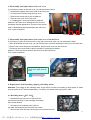
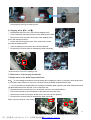
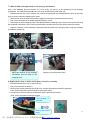
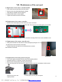
1
OS4000 Maintenance Service Manual
MODEL: OS4000
Voltage specification:110-120V
By Customer Service Department
1
PDF 文件使用 "pdfFactory Pro" 试用版本创建 www.fineprint.com.cn
Model
OS4000
Table of Contents
I……Specifications ……………………………………………………….3
II.…..Appearance of the chair …………………………………………….4
III…. Name and functions of components (remote controller) …………...5
IV…..Malfunction catalog………………………………………………6~8
V……Troubleshooting flow chart……………………………………..9~13
VI……Maintenance of the back rest …………………………………14~19
VII…..Maintenance of the seat part ………………………………….20~25
VIII….Maintenance of the footrest …………………………………..26~29
2
PDF 文件使用 "pdfFactory Pro" 试用版本创建 www.fineprint.com.cn
I. Specifications
3
PDF 文件使用 "pdfFactory Pro" 试用版本创建 www.fineprint.com.cn
II. Appearance of the chair
4
PDF 文件使用 "pdfFactory Pro" 试用版本创建 www.fineprint.com.cn
III.Name and functions of components (remote controller)
Remote controller
Auto-program buttons
Main control buttons
The adjustment button
for back body
Angle adjustment button
Length auto adjustment
buttons for legrest
LCD
Sensor receiver
Back speed/Air
intensity
Manual back
massage programs
5
PDF 文件使用 "pdfFactory Pro" 试用版本创建 ÿwww.fineprint.com.cn
IV. Malfunction catalog
Common Troubles and Maintenance Methods are listed as following:
Serial
Phenomenon
Description
Maintenance Methods
Refer to
The LCD isn’t illuminating:
① Replace Fuse(s).
① Page 25/20
② Replace the power supply
② (Ellipsis)
NO.
① Fuse(s) burn out ( the one
Is in the Power Source Box and
No Function
the other one on the main PCB).
When Starting.
②Power supply circuit poorly
01
cord.
③ Replace EMC Board.
③&④
Page 23-24/18
④ Replace main PCB.
connected.
③EMC Board fails.
④main PCB fails.
The LCD is illuminating:
① Replace the Up or Down
① Page 19/8
① The Up or Down Stroke
Stroke Photo-electricity.
②Page
Photo-electricity fails.
②Replace the main PCB.
23-24/18
No function
Main PCB fails.
③Width Inspection Board of
③ Page 18/7.1
when starting.
②Kneading is on without
PCB fails, replace it.
02
pressing any key when
starting and no response
by pressing other keys.
① The terminals of Width
①&②Plug the terminal
①&②&③
Inspection on main PCB
securely or replace the wires.
Page 18/7.1
and wires are poorly
③ Replace Width Inspection.
④Page
connected.
④ Replace the main PCB.
No Width
② The terminals of Width
switchover.
Inspection on massage
23-24/18
03
mechanical and wires are
poorly connected.
③ Width Inspection fails.
④ Main PCB fails.
6
PDF 文件使用 "pdfFactory Pro" 试用版本创建 www.fineprint.com.cn
04
①Terminal or Wire Poorly
①Plug the terminal securely
①Page
Contacts.
or replace the wires.
23-24/18
②Down-stroke Photo-
②Replace Down-Stroke
②&③
Electricity Subassembly Fails.
Subassembly.
Page 19/8
③Up-stroke Photo-electricity
③Replace Up-Stroke Sub-
④Page 17/6.2
Subassembly Fails.
assembly.
⑤Page
④Rolling Motor Fails.
④Replace Rolling Motor.
⑤Main PCB Fails.
⑤Replace main PCB.
①The terminals on main PCB
①Plug the terminal securely
①&③
and wires are poorly
or replace the wires.
Page 23-24/18
connected.
②Replace the kneading
②Page
②Kneading motor fails.
motor.
③Main PCB fails.
③Replace main PCB.
① The terminals on main
①Plug the terminal securely.
①&③
PCB and wires are poorly
②Replace the tapping motor.
Page 23-24/18
connected.
③Replace main PCB.
②Page 18/6.3
①Plug the terminal securely
①Page 20/11
or replace the wires.
②Page 20/10
No Rolling.
23-24/18
05
No kneading.
06
No tapping.
16-17/6.1
② Tapping motor fails.
③ Main PCB fails.
No response
when pressing
07
the keys on the
remote
①The terminals and wires are
poorly connected.
②The PCB in the remote
controller fails.
②Replace the remote
controller.
controller.
08
① The terminals of reclining
①Plug the terminal securely.
①&②Page
Back rest cannot
actuator and wires are poorly
②Replace reclining actuator.
22/15
be reclined or
connected.
③Replace main PCB.
② Page 23-24
raised
②The reclining actuator fails.
/18
③Main PCB fails.
7
PDF 文件使用 "pdfFactory Pro" 试用版本创建 www.fineprint.com.cn
09
① The terminals of foot rest
①Plug the terminal securely.
①&②Page
Foot rest cannot
actuator and wires are
②Replace foot rest actuator.
22-23/16
be raised or
poorly connected.
③Replace main PCB.
② Page 23-24
lowered.
②The foot rest actuator fails.
/18
③Main PCB fails.
①Plug the terminal securely.
①&②&③
valves and wires are poorly
②Replace the snuffle valves.
Page24/19
connected.
③Replace the inflator pump.
④Page
④Replace main PCB.
23-24/18
①The terminal of the snuffle
①Plug the terminal securely.
①&②&③
valves and wires are poorly
②Replace the snuffle valves.
Page24/19
connected.
③Replace the inflator pump.
④Page
④Replace main PCB.
23-24/18
①The terminal of the snuffle
①Plug the terminal well
①&②&③
valves and wires are poorly
②Replace the snuffle valves
Page24/19
connected
③Replace the inflator pump
④Page
②The snuffle valves fail
④Replace main PCB
23-24/18
①The terminal of the snuffle
No gas charging
10
in the seat-pad.
②The snuffle valves fail.
③The inflator pump fails.
④Main PCB fails.
No gas charging
11
in the foot rest.
②The snuffle valves fail.
③The inflator pump fails.
④Main PCB fails.
No gas charging
12
in the veil
for backrest
③The inflator pump fails
④Main PCB fails
No extending
①The terminals and wires are
①Plug the terminal well
①Page 25/22
Or shrinking
poorly connected
②Replace the main PCB
②Page
of the calves-rest
②The output voltage is not
③Replace the limit sensor
23-24/18
24VAC
④Replace the motor
③Page 27/24
13
③The limit sensor fail
④Page 26~27
④Motor fails
/23
8
PDF 文件使用 "pdfFactory Pro" 试用版本创建 www.fineprint.com.cn
V. Troubleshooting flow chart
Notes for repairing chair or replacing parts:
①Make sure the power is OFF before tearing down the wires, moving terminals or replacing parts.
②Semiconductors (such as IC and others) are very easy to be damaged by static, so when you touch
the PCB, please make sure your body is grounding (by wearing a girding static ring), or your hands are
touching with earthing grip (household electrical appliances putting to earth, such as fridges, washers
and so on) to release all static of the body.
1. No function when starting.
Is the LCD
illuminating?
Is the fuse melted?
N
Y
Are the terminals of Up
and Down Stroke
Subassembly
connected
是
securely?
Y
Replace fuse.
(Page 25/20)
N
Is the power cord
否
open-circuit?
Y
Replace the power
supply cord.
Connect
securely.
N
N
Y
Y
The switches of Up and Down
Stroke Subassembly fail or not?
Replace them.
(Page 19/8)
The EMC Board
fails or not?
Y
Replace it. (Page
23-24/18)
N
N
Is kneading on without pressing any
key when starting?
N
Width Inspection
Board fails or not?
否
Y
Replace Width
Inspection Board.
(Page 18/7.1)
N
Replace main PCB.
(Page 23-24/18)
9
PDF 文件使用 "pdfFactory Pro" 试用版本创建 www.fineprint.com.cn
ÿÿ
2. No width switchover.
Are the terminals of Width Inspection Board and main
PCB connected securely?
N
Connect securely.
Y
Y
Width Inspection Board fails or not?
Replace it.
(Page 18/7.1)
N
Replace main PCB.
(Page 23-24/18)
3. No function(fixed-spot or partial)
Are the terminals of main PCB connected
securely?
N
Connect securely.
Y
Replace Main PCB.
(Page 23-24/18)
4. No rolling
Are the terminals of rolling motor wire and
main PCB connected securely?
N
Y
Connect securely
Y
Replace the motor
(Page 17/6.2)
Rolling motor fails or not
N
Y
Replace it
(Page 19/8)
Up stroke Photo-electricity subassembly fails or not
N
Down stroke Photo-electricity subassembly fails or not
Y
Replace it
(Page 19/8)
N
Replace main PCB
(Page 23-24/18)
10
PDF 文件使用 "pdfFactory Pro" 试用版本创建 ÿwww.fineprint.com.cn
5. No kneading
N
Are the terminals of kneading motor wire and main
PCB connected securely?
Connect securely.
Y
Y
Kneading motor fails or not?
Replace the motor.
(Page 16/6.1)
N
Width Inspection Board fails or not?
Y
Replace it.
(Page 18/7.1)
N
Replace main PCB.
(Page 23-24/18)
6. No tapping.
N
Are the terminals of tapping motor wire and main
PCB connected securely?
Connect securely.
Y
Y
Tapping motor fails or not?
N
Replace the motor.
(Page 18/6.3)
Replace main PCB.
(Page 23-24/18)
7. Remote controller doesn’t work.
N
Are the terminals of remote controller wire and
main PCB connected securely?
Y
The conductive rubber fails or not?
Connect securely.
Y
Replace it.
(Page 20/11)
N
Replace the remote controller.
(Page 20/10)
11
PDF 文件使用 "pdfFactory Pro" 试用版本创建 ÿwww.fineprint.com.cn
8. Actuator doesn’t work.
N
Are the terminals of
reclining actuator and main
PCB connected securely?
N
Connect
securely.
Are the terminals of foot rest
actuator and main PCB
connected securely?
Y
Connect
securely.
Y
Y
The reclining actuator
fails or not?
Replace it.
The foot rest actuator
fails or not?
(Page 22/15)
N
Y
Replace it.
(Page 22-23/16)
N
Replace main PCB.
(Page 23-24/18)
9. No gas charging.
Are the terminals of snuffle
valve for bags in the seat
pad
and
main
PCB
connected securely?
N
Connect
securely.
N
Are the terminals of snuffle
valve for bags in the Foot
Rest and main PCB
connected securely?
Y
Connect
securely.
Y
Y
Snuffle valve fails
or not?
Replace it.
(Page26/19)
Snuffle valve fails or not?
N
Y
Replace it.
(Page24/19)
N
Are the terminals of
inflator pump and main
PCB connected securely?
N
Connect
securely.
Are the terminals of inflator
pump and main PCB connected
securely?
Y
N
Connect
securely.
Y
Inflator pump fails or not?
Y
Replace it.
Inflator pump fails or not?
(Page24/19)
N
Y
Replace it.
(Page24/19)
N
Replace main PCB.
(Page 23-24/18)
12
PDF 文件使用 "pdfFactory Pro" 试用版本创建 ÿwww.fineprint.com.cn
10. No gas charging in the outer coating of backrest
N
Plug terminals well
The terminal of snuffle valves connected
well or not?
Y
Y
The snuffle valves fail or not?
N
The terminal of the inflator pump
connected well or not?
Replace the snuffle valves
(Page24/19)
N
Plug terminals well
Y
Y
The inflator pump fails or not?
N
Replace the inflator pump
(Page24/19)
Replace main PCB
(Page 23-24/18)
12. No extending or shrinking of the calves-rest
N
The terminal of the calves-rest
connected well or not?
Plug terminals well
Y
N
The wire with terminal connected
well or not?
Plug the wire with terminals well
Y
The limit sensor fail or not?
Y
N
The terminal of the motor connected
well or not?
N
Replace the limit sensor
(Page 27/24)
Plug terminals well
Y
Y
Motor of the calves-rest fails
Replace the motor
(Page 26-27/23)
N
Replace main PCB
(Page 23-24/18)
Common trouble about electric control and processing methods of OS4000 are mentioned above. It is
for indication only.
13
PDF 文件使用 "pdfFactory Pro" 试用版本创建 ÿwww.fineprint.com.cn
VI. Maintenance of the back rest
1. Disassembly and replacement of back pad
① Find the zipper on the top of the back rest. Unzip it, then the back pad can be removed.
② There are two air hoses at the bottom of the back pad, pull out the connectors if a replacement needed.
③ There is a zipper at the bottom of the back pad. Unzip it and lift the sponge, then you can see the air
bags there.
④ Pull out the connectors of the hoses, then you can replace the air bag(s) if needed.
The zipper on the top of the backrest
The zipper at the bottom of the backrest
The hoses of the back pad
Pull out the hoses
2. Disassembly and replacement of the backrest
If the complete backrest is broken and need to be replaced, please consult the steps as below.
① Find the “stopper” under the backrest and press it , then you can fold backrest on seat part
② Find the wire plugs and pull out them.
Note: Insert the wire plugs back
black to black and gray to gray,
otherwise damage to the chair
may result
⑤ Disconnect the air hose of the backrest.
③ Unattach the connecting rod and the U stay fork of the reclining actuator with a flat head rivet, and pull
out the split pin.
④ Lift the backrest at 90 degrees, then take it away from the chair.
14
PDF 文件使用 "pdfFactory Pro" 试用版本创建 www.fineprint.com.cn
ÿÿ
Lift the backrest
at 90 degrees.
A.
B.
C.
D.
Connecting rod (on the backrest)
U stay fork of reclining actuator (on the seat)
Flat head rivet
Split pin
Disconnect the air hose of the backrest
3. Replacement of cloth of the front cover
① Unfasten the zipper of the back pad, and lay the back pad on the seat pad.
② You can find the zipper of the cloth at the left side. Unzip it and replace the cloth if needed.
Lay the back pad on the seat part
Unfasten the zipper zip
15
PDF 文件使用 "pdfFactory Pro" 试用版本创建 ÿwww.fineprint.com.cn
4. Disassembly and replacement of the rear cover
If you find any cracks on the rear cover, you can proceed as follow:
① Unfasten the zippers of the outer cloth of the rear cover.
② Find 4 pieces of screws fixing the rear cover.
③ Remove the screws with a plus screwdriver.
④ Then the rear cover can be removed.
⑤ If it’s damaged, a new one should be replaced.
Attention: Take care not to damage the rear cover to
avoid bad external appearance. Proceed in the reverse
order of disassembly when assembling the rear cover.
Tool: a plus screwdriver
Screws securing the rear cover
5. Disassembly and replacement of the front cover of the back rest
If you find any cracks on the front cover or any rips in the inside cloth, you can proceed as follow:
①After disassemble the rear cover, you can find 6 pieces of screws fastening the front cover to back frame.
②Remove the screws with a plus screwdriver, then the front cover can be removed.
③Proceed in the reverse order of above operation if replacement needed.
Attention: There are blocks between the front cover and back frame.
Tool: a plus screwdriver
Screws fastening the front
cover to the back frame (6
PCS)
6. Replacement of the kneading, tapping and rolling motors
Attention: The voltage of this massage chair is high and the motors are rotating in high speed, so make
sure the power is OFF before disassembly. For safety, you should remove plug from outlet.
6.1 Kneading motor(DC -24V)
① Disassemble the rear cover of the back rest,
and find the belt at top of the massage mechanism,
then loosen the belt.
② Find the wire of kneading motor, and cut
the cable ties tightening the wire with wire cutters.
③ Remove the close-end wire connectors covering the wires with
Kneading motor
PDF 文件使用 "pdfFactory Pro" 试用版本创建 ÿÿ
www.fineprint.com.cn
16
nipper pliers, then disconnect the wires.
④ Find 4 pieces of screws fixing the kneading motor to the sheet-metal,
remove the screws with a plus screwdriver.
⑤ Replace a new one if it does work.
⑥ Proceed in the reverse order of disassembly when replacing a new one.
Note:You should adjust the position of the small belt wheel, so the small and big belt wheels are in the
same plane to prolong the life-span of the belt.
Cut the cable ties and remove
Tools
close-end wire connector
6.2 Rolling motor(DC -24V)
① Disassemble the rear cover of the back rest, find the massage mechanism.
② Find the rail on the top of backrest and remove the screws to disassemble it.
③Disassemble the massage mechanism from the chair.(refer to 7.2)
④ Remove rolling car take from rack rail, there are 2 ways to choose, but “a” is
more convenient than “b”.
Rolling motor
a) Make the rolling motor power on, then revolve it until the rolling car take from backrest.
b) Use tools turn around axletree to revolve until the rolling car take from backrest.
⑤ Find 5 pieces of screws fixing the Rolling motor to the sheet-metal, remove the screws with a plus
screwdriver.
⑥ Replace a new one if it does work.
Remove the screws
(2pcs)
Turn around axletree to
revolve until the rolling
car take from backrest.
17
PDF 文件使用 "pdfFactory Pro" 试用版本创建 駿Ì
www.fineprint.com.cn
Screws securing the rolling motor (3 pcs)
Screws (5pcs) securing the Rolling motor
6.3 Tapping motor(DC -24V):
① Disassemble the rear cover, then find the tapping motor.
② Cut the cable ties securing the wire on the sheet-metal of EMC.
③ Remove the close-end wire connectors of the tapping motor
wires, then disconnect them.
④ Loosen the belt of tapping motor, then remove the screws
securing the tapping motor.
⑤ Then the tapping motor can be removed and replaced.
⑥ Proceed in the reverse order of disassembly when assembly.
Tapping motor
Close-end wire connector of tapping motor
7. Maintenance of the massage mechanism
7.1Replacement of the Width Inspection Board
Note:①If the massage mechanism is just kneading but no tapping or rolling, or it doesn’t work when power
is on, and the main PCB is ok, in this we can think of that the Width Inspection Board fails.
② It’s not necessary to disassemble the massage mechanism when replacing the Width Inspection Board,
just disassemble the front and rear cover of the back rest.
① Disassemble the front and rear cover of the back rest as it is mentioned above.
② Pull out the terminal on the board and cut the cable ties fixing the wires.
③ Remove the screws securing the board, then a new one can be replaced.
④ Proceed in the reverse order of disassembly when assembly.
Tools: a plus screwdriver, wire cutters
18
1 terminals on the board
Screws(2pcs)securing the board
PDF 文件使用 "pdfFactory Pro" 试用版本创建 駿Ì
www.fineprint.com.cn
7.2 Disassembly and replacement of the massage mechanism
Note: If the swinging arms are broken or it is too noisy, you can try to do something to the massage
mechanism. You should disassemble the rear cover and the cloth of the back rest.
① Disassemble the rear cover of back rest, remove the back pad, and disassemble the cloth of the back
rest, cut all the cable ties tightening the wires.
② Remove the close-end wire connectors of tapping motor wires, then disconnect the wires.
③ Pull out the terminals of the Width Inspection Board, 3 PCS.
④ Take down the belt of tapping motor, then disassemble the tapping motor. Remove the screws securing
the massage mechanism on the running frame and the screws securing nylon clamp which fixes wires.
⑤ Adjust the position of the massage mechanism and the width of the swinging arms, until the massage
mechanism is taken off.
Screws securing the mechanism
Adjust the position of the massage
mechanism and the width of the
swinging arms
Massage mechanism taken down
8. Replacement of up or down stroke photo-electricity assembly
① Disassemble the rear cover of the back rest.
② Pull out the terminal of the wire.
③ Remove the screws tightening the PCB of up or down stroke photo-electricity assembly
to the sheet-metal with a plus screwdriver and nipper pliers.
④ Proceed in the reverse order of disassembly when replacement needed.
Tools: a plus screwdriver and nipper pliers
The terminal of
the wire
Remove the screws
(3pcs)
PDF 文件使用 "pdfFactory Pro" 试用版本创建 駿Ì
www.fineprint.com.cn
19
VII. Maintenance of the seat part
9. Replacement of the remote controller holder
①
②
③
④
⑤
Pull out the remote controller from the holder.
Remove the screw bolt tightening the holder.
Take away the holder from the support.
Install a new holder on the support.
Tighten the holder with the screw bolt.
Screw bolt
10. Replacement of the remote controller
① Remove the screws (9pcs) on the back cover of the controller
② Disconnect the wire terminal of controller PCB; Then remove the screws(2pcs) on the PCB
.
③ Then you can replace any parts of the controller including PCB, Front cover and Back cover.
11. Replacement of the remote controller wire
④ Along the controller wire and remove the screws(6pcs) fixing the “R” nip
and disconnect wire terminal of controller.
⑤ Replace the new wire and fix it on the board, then connect
the terminal of controller.
.
“R” nip
Screw bolt
12. Replacement of the front panel of seat part
①
②
③
④
Turn on the power and raise the foot rest to the highest position.
Operate the Zero-G 2 function to raise the seat-rest,
Remove the screws(12pcs) securing the front panel.
Then the front panel can be removed, replace it with a new one, and tighten it with screws.
Raise the foot rest to the
Screws(12pcs) securing the front panel
highest position
PDF 文件使用 "pdfFactory Pro" 试用版本创建 駿Ì
www.fineprint.com.cn
20
13. Replacement of the side board
①
②
③
④
⑤
⑥
Disassemble the backrest from the chair
Use a cable tie to unfasten the seat pad from the chair by the zippers.
Remove the screws (4pcs) securing the side board.
Disconnect the air hose of the side cover.
Lift the side boards at 90 degrees, then disassemble it from the chair.
Proceed in the reverse order of disassembly when replacement needed. But please note that
when you fix the side cover make sure the air hose is not pressed by the seat frame.
Removed the screw
The back of side board
Zipper
Removed the screw
The front of side board
Screws (2pcs) securing the front panel
Last, lift up the side board
21
PDF 文件使用 "pdfFactory Pro" 试用版本创建 ÿwww.fineprint.com.cn
14. Replacement of the seat pad
①
②
③
④
Disassemble the backrest from the chair
Use a cable tie to unfasten the seat pad from the chair by the zippers.
Pull out the air hose Y- connector of the seat pad.
Find the connector of the vibration motor in the seat pad, cut the cable ties tightening the wire and
connector, disconnect the connector.
⑤ Then the seat pad can be replaced.
⑥ Proceed in the reverse order of disassembly when assembly.
Air hose Y- connector
Cable ties tightening the
wire and connector
15. Disassembly of the reclining actuator
① Disassemble the backrest from the chair, then find the reclining actuator
② Along the connecting wires of the reclining actuator to find the
2 connectors, then disconnect them.
③ Remove the upper part of the front boards on the right.
④ Then the reclining actuator can be disassembled.
⑤ Proceed in the reverse order of disassembly when assembly.
Reclining actuator
The connectors of the reclining actuator
Flat head rivet securing the reclining
actuator on the U stay fork
16. Disassembly of the foot rest actuator
① Disassemble the backrest from the chair, then find the reclining actuator
② Along the connecting wires of the reclining actuator to find the
2 connectors, then disconnect them.
③ Raise the foot rest to the extreme position, then find each end
of the actuator is fixing on the U stay fork. There are two plastic bush
rings in the hole.
Attention: You must use the brace to support the footrest, avoid the footrest
Footrest actuator
22
PDF 文件使用 "pdfFactory Pro" 试用版本创建 ÿwww.fineprint.com.cn
drop suddenly while pulling out plastic bush rings.
④ Pull out plastic bush rings, then the reclining actuator can be disassembled.
⑤ Proceed in the reverse order of disassembly when assembly.
The connectors of the footrest actuator
U stay forks
17 Disassembly of the zero gravity actuator
① Insert the power cord plug into an electrical outlet, turn the power switch to the “I” position for idle mode.
Then operation the controller to raise the foot rest to the extreme position.
②Remove the bottom part of the front boards.
③ Along the connecting wires of the zero gravity actuator to find the 2 connectors, then disconnect them.
④ Find each end of the actuator is fixing on the U stay fork.
There are two plastic bush rings in the hole.
Attention: You must use the brace to support the footrest,
avoid the footrest drop suddenly while pulling out plastic bush rings.
⑤ Pull out plastic bush rings, then the zero gravity actuator
can be disassembled.
⑥ Proceed in the reverse order of disassembly when assembly.
Footrest actuator
18 Replacement of the main PCB
① Turn off the power, then lay the back rest on the seat pad and pull out the terminals of the back rest.
② Remove the screws(2pcs) securing the box of the main PCB on the iron tubes.
③ If you just remove the upper cover of main PCB box only, just need to operate the Zero-G 2 function to
raise the seat-rest, then remove the screws(9pcs) on the box to take down the up cover of the main
PCB box
23
PDF 文件使用 "pdfFactory Pro" 试用版本创建 ÿwww.fineprint.com.cn
④ Pull out all the terminals on the main PCB, disconnect the PCB supports, then the main PCB can be
removed.
⑤ Proceed in the reverse order of disassembly when assembly.
Remove the screws(9pcs) on the
box to take down the up cover of
the main PCB box
Main PCB
Air valves
Inflator pump1
transformer
Inflator pump2
Comment: You can replace the part(s) that may be damaged on the board referring to the picture above,
which to remove the screws or connectors securing the damaged part(s).
19 Replacement of the inflator pump and the snuffle valves
Snuffle valves
Inflator pumps
① Turn off the power, then lay the back rest on the seat pad and pull out the terminals of the back rest.
② Remove the screws(2pcs) securing the box of the main PCB on the iron tubes.
③ Operate the Zero-G 2 function to raise the seat-rest, then remove the screws(9pcs) on the box to take
down the up cover of the main PCB box
④ Pull out the terminals of inflator pump and snuffle valves. Pull out the air hose connectors
⑤ Pull out 4 pieces of the rubber posts with nipper pliers, then the inflator pump can be removed.
⑥ Remove the screws tightening the snuffle valves, then the snuffle valves can be replaced.
⑦ Proceed in the reverse order of disassembly when assembly.
24
PDF 文件使用 "pdfFactory Pro" 试用版本创建 www.fineprint.com.cn
ÿÿ
20. Replacement of power supply fuse
② Find the fuse at the bottom of the seat part.
Turn the fuse holder in the counterclockwise
direction with a finger nail or a minus screwdriver.
③ Take out the fuse from the fuse holder and replace with a new one.
④ Put in the holder and turn the fuse holder in the clockwise direction,
then it will be fixed.
Fuse holder taken away
Attention:
①Make sure to use a glass tube fuse(the same type).
②Make sure to turn “OFF” the power supply and remove the power cord plug of the main unit from the
receptacle.
21. Replacement of the caster wheel
① Remove the screws securing the rubber support.
② Pry the caster wheel with a minus screwdriver and the caster can be replaced.
③ Proceed in the reverse order of disassembly when assembly.
Screws securing the rubber
support
25
PDF 文件使用 "pdfFactory Pro" 试用版本创建 www.fineprint.com.cn
IX. Maintenance of the foot rest
22. Replacement of the whole foot rest
① Turn on the power and raise the foot rest to the highest position. Then turn off the power.
② Remove the screws securing the front panel, take it away.
③ Find the air hose connectors of the foot rest, then disconnect them.
Screws securing the front panel
Air hose connectors of the foot rest
④ Pull out the connectors of the wires of foot rest.
⑤ Remove split pin, draw out flat head rivet securing the link rod of the foot rest.
Connectors of the wires of foot rest
Screw bolts and nuts
⑥ Unfasten the zipper between the seat pad and foot rest, then remove the screw bolts and nuts fixing the
foot rest on the seat part.
⑦ Proceed in the reverse order of disassembly when assembly.
23. Replacement of the footrest motor
① Remove split pin, draw out flat head rivet in the link rod, rotate the foot rest backward, then it will be
locked by the side boards.
② Remove the screws fixing the cover of foot rest, then it can be taken away.
③ Remove the close-end wire connectors, loosen the belt and take it away.
Screws(9PCS) fixing the cover of footrest
Belt and close-end wire connector
④ Remove the screws fixing the foot rest motor, then it can be removed.
⑤ Remove the screw fixing the wheel of belt on the motor shaft, then take a new motor, and assemble the
26
PDF 文件使用 "pdfFactory Pro" 试用版本创建 ÿwww.fineprint.com.cn
wheel of belt on the shaft.
⑥ Proceed in the reverse order of disassembly when assembly.
Note: You should adjust the position of the wheel of belt, so the two wheels are in the same plane.
24. Replacement of the front and back sensors of foot rest
① Remove split pin, draw out flat head rivet in the link rod, rotate the foot rest backward, then it will be
locked by the side boards.
② Remove the screws fixing the cover of foot rest, then it can be taken away.
③ Pull out the terminal of front or back sensor.
Sensor
Front and back sensors
④ Remove the screw bolts and nuts tightening the sensors on the sheet-metal with screwdriver and nipper
pliers. There are nuts between the PCB and sheet-metal. Remove the nuts.
⑤ Take a new sensor, then assemble the screw bolts and nuts on the PCB, then fix it on the sheet-metal
with nuts.
25. Replacement of connecting PCB of foot rest
① First the cover of foot rest should be removed.
② Pull out all the terminals of the connecting PCB, please remember the position of them.
③ Remove the screw bolts and nuts fixing the PCB on the sheet-metal, then it can be taken down.
Connecting PCB
Terminals of connecting PCB
④ Remove the nuts fixing on the PCB.
⑤ Take a new PCB, then proceed in the reverse order of disassembly when assembly.
26. Replacement of touchdown sensor of foot rest
① After disassembling the cover of foot rest, you can find the
touchdown sensor at the bottom of the foot rest.
② Pull out the terminal of the connecting PCB.
③Remove the screw bolts and nuts fixing the PCB
on the sheet-metal, then it can be taken down.
Touchdown sensor
PDF 文件使用 "pdfFactory Pro" 试用版本创建 www.fineprint.com.cn
27
④Remove the nuts fixing on the PCB.
⑤ Take a new PCB, then proceed in the reverse order of disassembly when assembly.
27. Replacement of upper outer coating of foot rest
① First you should disassemble the whole foot rest, and the cover of foot rest should be removed.
② Rotate the belt wheel to extend the foot rest to the longest position. Remove the screws tightening the
upper part of the foot rest.
③ Unzip the side zipper of the upper outer coating, then Remove the screws fixing the outer coating.
Screws tightening the upper part
Screws fixing the outer coating
④ Unfasten the zippers between the upper and lower part of the foot rest, then the outer coating can be
remove.
⑤ Proceed in the reverse order of disassembly when assembly.
28. Replacement of lower outer coating of foot rest
① First you should disassemble the whole foot rest, and the cover of foot rest should be removed.
② Rotate the belt wheel to extend the foot rest to the longest position. Remove the screw bolts fixing two
rubber supports at the bottom of the foot rest.
③ Unfasten the zipper at the bottom of the foot rest, then remove the screws fixing the PE board and take
away the PE board.
Rubber supports
Screws fixing the PE board
④ Remove the nuts fixing the lower part of the foot rest.
⑤ Rotate the cover of the wheel castor, then it can be removed. Removed screw bolt fixing the caster
wheel, then the castor can be removed.
Nuts fixing the lower part
Caster wheel
28
PDF 文件使用 "pdfFactory Pro" 试用版本创建 www.fineprint.com.cn
⑥ Remove the screws fixing the lower part of the foot rest, then the outer coating can be removed.
⑦ Proceed in the reverse order of disassembly when assembly.
Castor taken down
Screws fixing the lower part
29
PDF 文件使用 "pdfFactory Pro" 试用版本创建 www.fineprint.com.cn