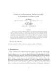
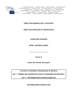
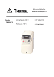
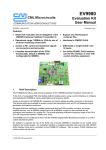
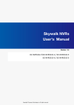
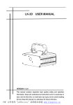
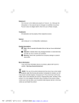
1
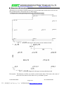
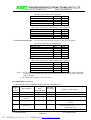
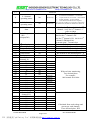
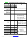
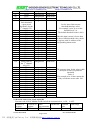
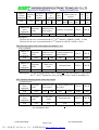
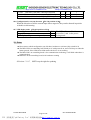
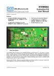
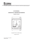
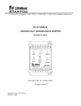
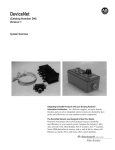
http://www.ce-transducer.com
[email protected]
Instructions of string combiner monitoring assembles
CE-ND
1. Overview.............................................................................................2
2. Part number.........................................................................................2
3. Features...............................................................................................3
4. Function ..............................................................................................3
5. Specification .......................................................................................3
6. Connection Diagram ...........................................................................4
7. Dimension and mounting ....................................................................5
8. Configuration......................................................................................6
9. MODBUS PROTOCOL......................................................................7
10. Configurations for the dip switches.................................................14
11. Notes...............................................................................................15
Tel:+86 755 83766915
Fax:+86 755 83763161
Page 1 of 15
PDF 文件使用 "pdfFactory Pro" 试用版本创建 Ùwww.fineprint.com.cn
http://www.ce-transducer.com
[email protected]
1. Overview
This series product could be used to be mounted in the string combiner as its monitoring
function part. It can measure the current, voltage, power of the solar panels, with RS485,
relay and analog outputs which could be connected with environment sensors, like wind,
temperature and sunlight radiation meter
2. Part number
Please follow the instruction below to fix the full part number, one square one code.
Series
C
E
N
D
Options
2
3
9
M
L
Series CE
Product series
N---For new energy industry
Input code
D---DC power ,current and voltage;
Z---DC current; U---DC voltage
Function code
1—8 channel;2—12 channel ;3—16 channel;
2---treble isolation
For new function
A---fuse board for negative input;
Output code
3---RS-485 with Modbus protocol;
T---Special output (For customized)
Power supply
9---100-1000VDC
Current connection
M---terminals,no aperture
Mounting
L---Screw
Accuracy& Input range
1.0;/ XXXV*XXA
Tel:+86 755 83766915
Fax:+86 755 83763161
Page 2 of 15
PDF 文件使用 "pdfFactory Pro" 试用版本创建 ÿwww.fineprint.com.cn
http://www.ce-transducer.com
[email protected]
3. Features
l
l
l
l
l
l
l
l
Two isolation principle version for option: hall effect and high precise resistance
Bi-direction measurement
PV-powered, saving installation time and material costs for the power supply
Max voltage input 1000V
Integrated with fuse holders, work for different size fuses, max. 1000V.
Two channel analog 0-10V& 0-20mA inputs for other environment sensors
With LED display
RS485 output with Modbus-RTU protocol
4. Function
l
l
l
l
l
l
l
l
l
Short circuit of the solar panel alarmed by LED display and data transmission
Switch input for DC breaker or lightning device status monitoring
Relay output for automatic control of DC breaker switch on and off
Analog inputs for temperature, sunlight radiation, wind speed sensors data acquisition
Output 12V or 24Vdc power for the extra environment sensors(optional)
6 digit LED display each channel current in circle, with power saving mode
Standard Mobus RTU protocol, the address, baud rate, data format could be modified in
local or remote control
Total voltage measurement, with power calculation for each channel
PV powered, no need extra power source device/ mains connection
5. Specification
Series
Input channel
Input range
Accuracy
Temperature drift
Communication
Data update period
Isolation
Operating
temperature
Humility
Power supply
Power consumption
Surge protection
Optional function
Relay output
Switch input
Analog input
CE-ND12
CE-ND22
CE-ND32
8 channel
12 channel
16 channel
DC 0-10A
1.0 for solar panel, 0.5 for analog inputs
500ppm
RS485、Modbus protocol、odd/even parity/ none checking
4800/9600/19200/57600bps
1S
Power supply/gathered input/digital output/voltage input/switch
input/relay output isolated from each other,2500V DC/1 min.
-25-+60°C
95%, no dew ,no corroding gas
220AC or PV powered100-1000VDC
50mA(100V); 12mA(1000V);
Power supply:4KV;voltage input terminals:4KV;
communication terminals: 2KV
1channel, 8A/AC250V(8A/DC 30V)
3 group inputs(Dry contact)
DC0(4)-20mA、DC0-10V(or customized)
Tel:+86 755 83766915
Fax:+86 755 83763161
Page 3 of 15
PDF 文件使用 "pdfFactory Pro" 试用版本创建 www.fineprint.com.cn
http://www.ce-transducer.com
[email protected]
6. Connection Diagram
There are 3 boards, control board, upper and bottom current combining board)
Fig 6.1 Connection diagram
Remark:
1. “+” here means positive current input while ”-” means negative, the number strands for
the corresponded channel, for example I1+ means positive current input of the fist
channel
2. Ensure the connections of winding displacement matched the input numbers, On CN1,
I1~I8 port for the 1~8 channel input, and on CN2, I9~I16 port for the 9~16 channel input.
3. The upper and bottom boards are flexible to be chosen according to the number of input
channels
Tel:+86 755 83766915
Fax:+86 755 83763161
Page 4 of 15
PDF 文件使用 "pdfFactory Pro" 试用版本创建 Ùwww.fineprint.com.cn
http://www.ce-transducer.com
[email protected]
7. Dimension and mounting
When there are more than 8 channel inputs, two current gathering board needed, each one can
take 8 channel input. The bottom one is a little bigger.
7.1 Diagram for current gathering boards (upper and bottom board)
Fig 7.1 Mounting diagram for the bottom current gathering board
Fig7.2 Mounting diagram for the upper current gathering board
Description:The diameter of all the screw holes on the board is 4mm. The locates (the centre of
the screw hole) shown in the shown in x,y coordinate system.
Tel:+86 755 83766915
Fax:+86 755 83763161
Page 5 of 15
PDF 文件使用 "pdfFactory Pro" 试用版本创建 Ùwww.fineprint.com.cn
http://www.ce-transducer.com
[email protected]
7.2 Diagram for controlling boards
Fig7.3 Mounting diagram for the controlling board
8. Configuration
Function Display
button menu
Adr
bAud
Left
Down
Current
per
channel
0-255
1200、2400、4800、
9600、19200、57600
mode
1stop、2stop、odd、
EvEn
code
None
Remard
The address of the adapter
Baud rate, bps
1stop:8 bits, no check,1 bit stop;
2stop:8 bits,2 bits stop(not available now);
odd:8 bits, odd check, 1 bit stop;
EvEn: 8 bits, parity check, 1 bit stop;
None
U.xxx.x:DC voltage (V)、I.xxx.x:total
current (A)
W.xxx.x:total power (kW)、
U.xxx.x、I.xxx.x、
i.xx.xx:the second analog input channel(mA
W.xxx.x、
i. xx.xx、
or V)、u.xx.xx:the first analog input
u.xx.xx、t.xx.x
channel(mA or V)、t.xxx.x: temperature
(℃)
None
1.x.xxx、……9.x.xxx、
On One press switch to one channel power(Kw),
A.x.xxx、b.x.xx、
Ex. “1.9.112”,means the power for the
C.x.xxx、D.x.xxx、
1stchannel is 9.112kW. And A、b、C、d、
E.x.xxx、F.x.xxx、
E、F、G stands for 10-16 channel separately.
G.x.xxx
None
01xx.xx、02xx.xx、
03xx.xx、……、
14xx.xx、15xx.xx、
16xx.xx
Right
Up
(power
per
channel)
Contents
One press switch to one channel current (A).
Ex., “0110.12”,means the current for the
1stchannel is 10.12A.
Tel:+86 755 83766915
Fax:+86 755 83763161
Page 6 of 15
PDF 文件使用 "pdfFactory Pro" 试用版本创建 www.fineprint.com.cn
http://www.ce-transducer.com
[email protected]
9.MODBUS PROTOCOL
9.1
Format of data
9.1.1 Format of message
9.1.1.1 Function code 01H/02H ── To read the switch input and relay output from the slave equipment.
The Message from the master equipment:
Address of the slave equipment
01H-FFH 1 byte
Function code
Address of the first register
Quantity of Registers
CRC code
01/02H
1 byte
2 bytes
2 bytes
2 bytes
The correct responded message from the slave equipment:
Address of the slave equipment
01H-FFH
1 byte
Function code
01H/02H
1 byte
Byte count
1 byte
Data section (contents of registers)
N* x 2 bytes
CRC code
2 bytes
*N = Quantity of Registers
9.1.1.2 Function code 03H ── To read data of registers of the slave equipment
The Message from the master equipment
Address of the slave equipment 01H-FFH
Function code
03H
Address of the first register
Quantity of Registers
CRC code
1 byte
1 byte
2 bytes
2 bytes
2 bytes
The correct responded message from the slave equipment:
Address of the slave equipment
01H-FFH 1 byte
Function code
03H
1 byte
Byte count
2* N*
1 byte
Data section (contents of registers)
N* x 2 bytes
CRC code
2 bytes
*N = Quantity of Registers
9.1.1.3 Function code 05H ── To write data to control the relay input
The Message from the master equipment
Address of the slave equipment 01H-FFH
Function code
05H
Address of the first register
Quantity of Registers
CRC code
1 byte
1 byte
2 bytes
2 bytes
2 bytes
The correct responded message from the slave equipment:
Address of the slave equipment 01H-FFH 1 byte
Function code
05H
1 byte
Address of the register
2 bytes
The data written to the registers
2 bytes
CRC code
2 bytes
Tel:+86 755 83766915
Fax:+86 755 83763161
Page 7 of 15
PDF 文件使用 "pdfFactory Pro" 试用版本创建 www.fineprint.com.cn
http://www.ce-transducer.com
[email protected]
9.1.1.4 Function code 06H ── To set (write) data for single register of the slave equipment
The Message from the master equipment
Address of the slave equipment 01H-FFH
Function code
06H
Address of the first register
Quantity of Registers
CRC code
1 byte
1 byte
2 bytes
2 bytes
2 bytes
The correct responded message from the slave equipment:
Address of the slave equipment 01H-FFH 1 byte
Function code
06H
1 byte
Address of the registers
2 bytes
The data written to the registers
2 bytes
CRC code
2 bytes
9.1.1.5 Function code 10H ── To set (write) data for multi-registers of the slave equipment
The Message from the master equipment
Address of the slave equipment 01H-FFH
Function code
10H
Address of the first register
Quantity of Registers
Byte count
2 x N*
The data written to the registers
CRC code
*N = Quantity of Registers
1 byte
1 byte
2 bytes
2 bytes
1 byte
2 x N*
2 bytes
The correct responded message from the slave equipment:
Address of the slave equipment 01H-FFH 1 byte
Function code
10h
1 byte
Address of the first register
2 bytes
Quantity of Registers
2 bytes
CRC code
2 bytes
Note: 1. For all Address of register, Quantity of registers and Contents of register (Data), their high
order byte is before their low order byte. But the low order byte of CRC code is before its
high order byte.
2. The length of the register is 16 bits (2 bytes).
9.2.1.1 Definitions of registers
Function code 03H of Modbus could read all the contents below
Address
Attribute
of
Data content
Data
of register
Remark(Data range)
register
representation
0
1
2
Name of the device
Version
Communication
unsigned int
unsigned int
unsigned int
Read only
Read only
Read/write
0X5549
1200,2400,4800,9600,19200,
57600
Could be written as 0,1,2,3
(Reference10.5)
0-255
address*
3
Baud rate*
unsigned int
Read/write
4
Check mode*
unsigned int
Read/write
*:The write function only be available while the fourth switch of S6 turned on 1, S6 is located on the controlling board.
Tel:+86 755 83766915
Fax:+86 755 83763161
Page 8 of 15
PDF 文件使用 "pdfFactory Pro" 试用版本创建 www.fineprint.com.cn
http://www.ce-transducer.com
[email protected]
5-7
8
9
10
Reserved
8-1 channel
operating status
16-9 channel
operating status
1-16 channel
alam
int
Read only
int
Read only
int
Read only
Read only
11
Switch input
(DI)
/Output(DO)
int
12
13
14
15
16
17
18
2nd analog input
1st analog input
Temperature
Gathered volt.
Total current
Total power
Current for 1st
channel( I1)
I2
I3
I4
I5
I6
I7
I8
I9
I10
I11
I12
I13
I14
I15
I16
Power for 1st
channel( P1)
P2
P3
P4
P5
P6
P7
P8
int
int
int
int
int
int
int
Read only
Read only
int
int
int
int
int
int
int
int
int
int
int
int
int
int
int
int
Read only
Read only
Read only
Read only
Read only
Read only
Read only
Read only
Read only
Read only
Read only
Read only
Read only
Read only
Read only
int
int
int
int
int
int
int
Read only
Read only
Read only
Read only
Read only
Read only
Read only
19
20
21
22
23
24
25
26
27
28
29
30
31
32
33
34
35
36
37
38
39
40
41
Read only
Read only
Read only
Read only
bit1 , bit0
0 , 0 =Channels un-installation,no Led blink
0 , 1=Open circuit for over current,red Led blink
1 , 0=Work normally,green Led blink
1 , 1=The direction of the current is negative
The bit1,bit0 of address 8 correspond to input status
of channel one, bit3,bit2 for channel two, and so on
bit0 for the 1st channel,bit1 for 2nd
channel…bit15 for 16th channel. “1”
refers to alarm
bit0 for the 1st channel’s DO(low 8 bit);
bit8 for the 1st channel’s DI,
bit9 for 2nd channel’s DI,bit10 for 3rd
channel’s DI(high 8 bit)
0 means open,1 means close
Data rounded up to percentile, mA/V
Data rounded up to percentile,mA/V
Be accurate to one decimal place,℃,
Be accurate to one decimal place, V
Be accurate to one decimal place,A
Be accurate to one decimal place,KW
Read only
With real-time monitoring,
Two decimal place
For example:
1000 strands for10.00A
Read only
Calculated from total voltage and
current per each channel.
Three decimal place, KW
Tel:+86 755 83766915
Fax:+86 755 83763161
Page 9 of 15
PDF 文件使用 "pdfFactory Pro" 试用版本创建 www.fineprint.com.cn
http://www.ce-transducer.com
42
43
44
45
46
47
48
49
50-65
66-68
69-78
79
P9
P10
P11
P12
P13
P14
P15
P16
Counting for1-16
channel’s open
circuit times
Counting for the
open circuit
times of 1~3
channel switch
input
Reserved
Definition of
relay output
80
int
int
int
int
int
int
int
int
unsigned int
83
84
85
86
87
88
89
90
91
92
93
For example:1000 means 1.000KW
here
Read only
Reserved
only
Reseved
unsigned int
Read/write “1’Relay would close while the current
lower/over than the threshold value; in
other situations , relay release
“2’ relay would close while the current
lower/over than the threshold value;
with other inputs, relay release.
Meanwhile the relay could be
controlled by the communication bus
Other value except “1”,The
communication bus controls the relay
If effective value as 1-255, the relays
Read/write
would take action automatically after 1255 seconds;
If effective value fixed as 0, the action
of the relay will be controlled by
communication, couldn’t be release
automatically
Reserved
Read/write
unsigned int
unsigned int
unsigned int
unsigned int
unsigned int
unsigned int
unsigned int
unsigned int
unsigned int
unsigned int
unsigned int
Read/write
Read/write
Read/write
Read/write
Read/write
Read/write
Read/write
Read/write
Read/write
Read/write
Read/write
unsigned int
unsigned int
Over current
threshold for 1st
channel(TH1)
TH2
TH3
TH4
TH5
TH6
TH7
TH8
TH9
TH10
TH11
TH12
Read only
Read only
Read only
Read only
Read only
Read only
Read only
Read only
unsigned int
Response time
for the relay
output
81
82
[email protected]
Set for over current threshold(absolute
value)
For example, write 1200 means the
threshold is 12.00 A.
The default threshold value is 1.2 times
of the rated input.
When the input current is over the
threshold value, check the register with
10 address of the corresponding alarm
status.
Tel:+86 755 83766915
Fax:+86 755 83763161
Page 10 of 15
PDF 文件使用 "pdfFactory Pro" 试用版本创建 www.fineprint.com.cn
http://www.ce-transducer.com
94
95
96
97
98
99
100
101
102
103
104
105
106
107
108
109
110
111
112
113
114
115
116
117
118
119
120
121
122
123
124
125
126
127
128
129
TH13
TH14
TH15
TH16
Lower current
limit threshold
(open circuit
threshold) for the
1st channel: TL1
TL2
TL3
TL4
TL5
TL6
TL7
TL8
TL9
TL10
TL11
TL12
TL13
TL14
TL15
TL16
Delay time for
the 1st channel
relay: D1
D2
D3
D4
D5
D6
D7
D8
D9
D10
D11
D12
D13
D14
D15
D16
unsigned int
unsigned int
unsigned int
unsigned int
unsigned int
[email protected]
Read/write
Read/write
Read/write
Read/write
Read/write
unsigned int
unsigned int
unsigned int
unsigned int
unsigned int
unsigned int
unsigned int
unsigned int
unsigned int
unsigned int
unsigned int
unsigned int
unsigned int
unsigned int
unsigned int
unsigned int
Read/write
Read/write
Read/write
Read/write
Read/write
Read/write
Read/write
Read/write
Read/write
Read/write
Read/write
Read/write
Read/write
Read/write
Read/write
Read/write
unsigned int
unsigned int
unsigned int
unsigned int
unsigned int
unsigned int
unsigned int
unsigned int
unsigned int
unsigned int
unsigned int
unsigned int
unsigned int
unsigned int
unsigned int
Read/write
Read/write
Read/write
Read/write
Read/write
Read/write
Read/write
Read/write
Read/write
Read/write
Read/write
Read/write
Read/write
Read/write
Read/write
Set for lower limit current
threshold(absolute value)
For example, write 30 to set the
threshold as 0.3 A.
The default threshold value is 0.4A
When the input current is lower than
the lower limit threshold value, check
the register with 10 address of the
corresponding alarm status.
The response time for the relays while
the input current is beyond the
threshold.
Unite: S
For example wire 10 here means the
relay would take action after 10S.
9.3 Read the status of the switch inputs(DI)
Function code 02H of Modbus could read all the contents below, 1=0N ,0=0FF
Address of
Contents of Data
Read/write Function
Data range
register
register
representation
code
0000H
DI1
BIT
R
02
1=ON,0=OFF
Tel:+86 755 83766915
Fax:+86 755 83763161
Page 11 of 15
PDF 文件使用 "pdfFactory Pro" 试用版本创建 www.fineprint.com.cn
http://www.ce-transducer.com
0001H
0002H
DI2
DI3
BIT
BIT
[email protected]
R
R
02
02
1=ON,0=OFF
1=ON,0=OFF
9.4 Read the status of the relay outputs(DO)
Function code 01H of Modbus could read all the contents below, 1=0N ,0=0FF
Address of
Contents of Data
Read/write Function
Data range
register
register
representation
code
0000H
DO1
BIT
R
01
1=ON,0=OFF
9.5 Read the alarming status of the relay outputs
Function code 05H of Modbus could read all the contents below, 1=0N ,0=0FF/release
Address of
Contents of
Read/write Function
Data range
register
register
code
0000H
DO1
W
05
0xFF00 =ON, 0x0000 =OFF
Note: The function code 05H works while the content is not “1” in the register with 79 address.
9.6 Examples
EX1, read the current data for channel 1 and 2
Sent the command:
Address of
Function Address of the
slave
Quantity of registers CRC-L CRC-H
code
first register
equipment
01H
03H
00H
12H
00H
02H
64H
0EH
Data returned:
Address of
Function
Data bytes
slave
Contents of register CRC-L CRC-H
code
count
equipment
01H
03H
04H
03H DBH 04H 02H
09H
4DH
st
Description:The data for the current of 1 channel is 03DBH=987D= 9.87A;
The data for the current of 2nd channel is 0402H=1026D=10.26A。
Ex 2: Set the response time of the relay output
Sent command:
Address of
Function Address of the Data written to
slave
CRC-L
code
first register
register
equipment
01H
06H
00H
50H
00H
05H
49H
Data returned:
Address of
Function Address of the Data written to
slave
CRC-L
code
first register
register
equipment
01H
06H
00H
50H
00H
05H
49H
Description:05H means the relay would take action after 5 seconds
EX3:Set the over current threshold for channel 1 to 3
Sent command:
Tel:+86 755 83766915
Fax:+86 755 83763161
Page 12 of 15
PDF 文件使用 "pdfFactory Pro" 试用版本创建 Ùwww.fineprint.com.cn
CRC-H
D8H
CRC-H
D8H
http://www.ce-transducer.com
Address
Address of
Function
of slave
the first
code
equipment
register
01H
10H
00H 52H
Quantity
of
registers
00 03
H
H
[email protected]
Data
bytes
count
06H
Data written to
register
04H
B0H
04H 04H
4CH B0H
CRC
-L
C7H
CR
CH
C6
H
Data returned:
Address of
Function
Address of the
Quantity of registers CRC-L CRC-H
slave
code
first register
equipment
01H
10H
00H
52H
00H
03H
21H
D9H
Description:
The data for the over current threshold of 1st &3rd channel is 04B0H=1200D= 12.00A;
The data for the over current threshold of 2nd channel is 044CH=1100D=11.00A。
EX4:Read the status of the switch inputs for channel 1 to 3
Sent command:
Address of
Function
Address of the Counting number for
slave
CRC-L CRC-H
code
first register
switch inputs
equipment
01H
02H
00H
00H
00H
03H
38H
0BH
Date returned:
Address of
Function
Data bytes
slave
Returned data
CRC-L CRC-H
code
count
equipment
01H
02H
01H
06H
21H
8AH
Description:06 converted into binary code is 00000110,the first channel is open while
the 2nd and 3rd channel are close, the higher 5 bits 0 with no meaning here.
EX5: Read the alarming status of the relay output
Command sent:
Address of
Function
Address of the Counting number for
slave
CRC-L CRC-H
code
first register
the relays
equipment
01H
01H
00H
00H
00H
01H
FDH
CAH
Data returned:
Address of
Function
Data bytes
slave
Returned data
CRC-L CRC-H
code
count
equipment
01H
01H
01H
01H
90H
48H
Description:01 converted into binary code is 00000001,relay is in off .The high 7 bits 0
are meaningless here.
Tel:+86 755 83766915
Fax:+86 755 83763161
Page 13 of 15
PDF 文件使用 "pdfFactory Pro" 试用版本创建 www.fineprint.com.cn
http://www.ce-transducer.com
[email protected]
10. Configurations for the dip switches
There are two dip switches (named S6 and S7) in the controlling board. 1=ON (close),
0=off(open)
10.1 Definitions for the dip switches
S7.
1
S7.
2
S7(1-8 positions)
S7. S7. S7. S7. S7.
3
4
5
6
7
S7.
8
Address set
S6(1-8 positions)
S6. S6.2 S6. S6.4 S6.5 S6.6 S6.7
1
3
Fix Communica Current
Set for baud
direction
Mo tion
rate
mode
de
S6.8
Displa
y
On/off
10.2 Address configuration(S7)
S7.8
0
0
S7.7
0
0
S7.6
0
0
1
1
1
1
1
1
S7.5
S7.5
S7.3
S7.2
0
0
0
0
0
0
0
0
……………………………
1
1
1
1
1
1
1
1
S7.1
0
1
Address
0
1
0
1
254
255
10.3 Baud rate configuration(The 1st, 2nd,3rd positions of S6)
Baud rate
9600bps
1200bps
2400bps
4800bps
57600bps
19200bps
19200bps
19200bps
S6.3
0
0
0
0
1
1
1
1
S6.2
0
0
1
1
0
0
1
1
S6.1
0
1
0
1
0
1
0
1
10.4 Configuration method (The 4th position of S6)
Configuration method
Hardware configuration (AD., baud rate,
communication mode)
Software configuration (AD., baud rate,
communication mode)
S6.4
0
1
Note: while S6.4 switches to
software fixing, the address, baud
rate and communication mode
won’t change, they would be
acquired and saved automatically.
10.5 Configuration for data format(The 5th and 6th position of S6)
Data format
10 bits:1-bit start, 8-bit data, 1-bit stop
Tel:+86 755 83766915
S6.6
S6.5
0
0
Software
fixing code
0
Fax:+86 755 83763161
Page 14 of 15
PDF 文件使用 "pdfFactory Pro" 试用版本创建 www.fineprint.com.cn
http://www.ce-transducer.com
[email protected]
1
0
1
11 bits: 1-bit start, 8-bit data, 2-bit stop (reserved)
11 bits:1-bit start, 8-bit data, even parity ,1-bit stop
11 bits:1-bit start, 8-bit data, odd parity,1-bit stop
0
1
1
1
2
3
10.6 Configuration for current direction(The 7th position of S6)
When the direction of all the current input shows negative, they can be showed in positive
with this switch turning.
10.7 LED display mode (The 8th position of S6)
LED
Keep LED on
LED display off (power saving mode)
S6.8
0
1
The LED will turn off without out
press after 1 min. in the power
saving mode
11. Notes
l Please ensure which configuration you did chose, hardware or software (Dip switch:S6.4)
l The RED LED3 on controlling board blink per 2s with powered on; and it will keep on when the
button pressed; if the LED3 don’t blink means the device is not working
l The RED LD51 on controlling board is for communication indicating, it will blink when there is
communication
l Button S5 on the controlling board is for hardware resetting
©Version:V11.7;SSET keep the right for updating
Tel:+86 755 83766915
Fax:+86 755 83763161
Page 15 of 15
PDF 文件使用 "pdfFactory Pro" 试用版本创建 Ùwww.fineprint.com.cn