1
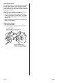
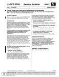
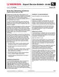
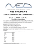
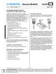
Service Bulletin Applies To: 00-088 January 24, 2014 ALL Models On-Car Brake Disc Refinishing Equipment and Guidelines (Supersedes 00-088 Brake Disc Refinishing Using Kwik-Way and Accu-Turn Lathes, dated November 5, 2013, to revise the information marked with the black bars) REVISION SUMMARY The Pro-Cut lathe was added to the INTRODUCTION and a new section was created for Pro-Cut lathes. INTRODUCTION American Honda does not allow replacement of brake discs under warranty unless the brake disc is beyond its service limit for refinishing. If the brake disc is within its service limit, you must refinish it. Maximum refinishing limits may be found in the Conventional Brakes section of the appropriate electronic service manual. Refinish brake discs only when they are scored or out of specification for runout or parallelism. See the appropriate electronic service manual for the specifications. American Honda requires refinishing of the front brake discs with an on-car brake lathe that mounts to the steering knuckle or hub using specially designed Honda/Acura specific adapters. It is critical to use an on-car steering knuckle-mounted lathe because it corrects the hub and disc runout as an assembly. Even a very small amount of runout, which may not be felt initially, will grow and will be felt as brake pulsation as the discs are subjected to heat and wear over time and mileage. You must use one of the following lathes to refinish a brake disc under warranty: • Pro-Cut: T/N PCIPFM92HON • Kwik-Way: T/N KWY-108000501 • Accu-Turn: T/N ACCHONOCLPKG NOTE: The Kwik-Way and Accu-Turn lathes and their related parts and adapters have been discontinued from the tool manufacturers and are no longer available for purchase through the Honda Tool and Equipment Program. Any KWY part number listed within this bulletin are for identification purposes only. 2014 American Honda Motor Co., Inc. – All Rights Reserved A power driver is required for the S2000 and is highly recommended for all other models. The Kwik-Way power driver model number is KWY-108000110. Here are some advantages of using power drivers: • The disc is rotated at the optimum speed for a smooth and consistent cut. • There is no need to climb in and out of the vehicle to start and stop the engine or to shift the transmission. • Securing the opposite wheel with a tie-down strap is not required. • There is no waiting for the engine to return to idle and no concern about engine speed changes that can adversely affect brake disc cut and finish. • The Traction Control System (TCS) is not involved. • Consistent cutting speed increases cutting tool life. ORDERING INFORMATION The Pro-Cut lathe and Honda/Acura adapters are available through the Honda Tool and Equipment Program. To order, go to the Honda Tool and Equipment program catalog on the iN (select Service > Service Bay > Tool and Equipment Program > Online Catalog), or call 888-424-6857. Phone lines are open Monday through Friday from 7:30 a.m. to 7:00 p.m. Central Time. WARRANTY CLAIM INFORMATION None, this bulletin is for information only. ATB 624-50912 (REV 8) (1401) 1 of 6 CUSTOMER INFORMATION: The information in this bulletin is intended for use only by skilled technicians who have the proper tools, equipment, and training to correctly and safely maintain your vehicle. These procedures should not be attempted by “do-it-yourselfers,” and you should not assume this bulletin applies to your vehicle, or that your vehicle has the condition described. To determine whether this information applies, contact an authorized Honda automobile dealer. PRO-CUT LATHE Make sure you are using the correct adapter and refinish the brake disc. • 4 Lug Honda/Acura Adapter, Red Label (56 mm/4 x 100 mm): T/N PCI50996 • 5 Lug Honda/Acura Adapter, Blue Label (64 mm/5 x 114.3 mm and 120 mm): T/N PCI50997 • 4 and 5 Lug Honda/Acura Adapter, Yellow Label (70 mm/ 5 x 114.3 and 4 x 114.3 mm): T/N PCI50998 PCI50996 4 LUG HONDA/ACURA ADAPTER, RED LABEL (56 mm / 4 x 100 mm) PCI50997 5 LUG HONDA/ACURA ADAPTER, BLUE LABEL (64 mm / 5 x 114.3 mm) PCI50996 4 & 5 LUG HONDA/ACURA ADAPTER, YELLOW LABEL (70 mm / 5 x 114.3 mm) For more information about how to refinish the brake disc, which includes information about setting up the vehicle, setting up the lathe, and cutting the discs, refer to the Pro-Cut Lathe Technical Manual, or call Pro-Cut at 800-543-6618 to schedule training. NOTE: You must use the listed Pro-Cut hub adapters to meet Honda’s required specifications for run-out on warranty repairs. Do not use Pro-Cut’s universal hub adapters, because they do not meet Honda’s run-out specifications. Pro-Cut Honda Adapters are available through the Honda Tool and Equipment Program on the Interactive Network (iN). Click on Service, Service Bay, Tool and Equipment Program. Click on Alignment, Wheel, and Brake Equipment, and then click On-Car Brake Lathes and Accessories. KWIK-WAY AND ACCU-TURN LATHE Use the following guidelines that show the Kwik-Way lathe setup; the Accu-Turn brake lathe setup is similar. NOTE: You can use an on-car lathe to refinish the rear discs on some models if the rear caliper mounts are low enough to allow the lathe to clear the vehicle body. Refer to REAR BRAKE DISC for more information. Setting Up the Vehicle Put the transmission in Neutral. If you are not using the power drive system, start the engine, and let it warm up to its normal operating temperature so the idle speed will stabilize to its lowest rpm. NOTE: AWD vehicles must have all four wheels off of the shop floor. Raise the vehicle on a lift. Check for loose wheel bearings. You must replace loose wheel bearings before you refinish the brake discs. If you do not, the brake lathe will not correct for brake disc runout, resulting in an uneven finish and brake pulsation. Remove the front wheels, then reinstall the wheel nuts with flat washers to compensate for the removed wheel. Torque the wheel nuts to the required specification (see the appropriate electronic service manual). Remove the caliper assembly. Use a wire or an S-hook to hold the caliper to the spring or damper tower. Do not kink the brake hose or use it to support the caliper. If you are not using the power drive system and the vehicle has TCS or VSA, make sure you install a brake pad spreader between the pads on the hanging caliper. Also, make sure the TCS or VSA is turned off anytime the engine is started. If the system is not turned off, the brakes could activate, causing the brake pads on the hanging caliper to hit each other or the caliper pistons to fall out. Install the vibration damper on the brake disc. If you are not using the power drive system, make sure you install the protective band around the wheel nuts. VIBRATION DAMPER 2 of 6 PROTECTIVE BAND 00-088 If you are not using the power drive system, use a fabric tie-down strap to secure the brake disc that is opposite to the one you are refinishing. If you are working on a Prelude with ATTS, do not use a tie-down strap; let both wheels turn freely. Mounting the Brake Lathe Remove the tool bed from the brake lathe, then mount the brake lathe to the steering knuckle with a Honda 1-piece speed mount. These mounts provide quicker, more accurate mounting. Honda 1-Piece Speed Mounts • P/N KWY-108006000 (for most models) • P/N KWY-108007500 (Odyssey, Pilot, and Ridgeline with two-piston calipers) • P/N KWY-108007600 (2009 and newer Pilot) KIT COMPONENTS [Torque the bolts to 33 N.m (24 lb-ft); do not use an impact wrench.] FABRIC TIE-DOWN STRAP FRONT BRAKE DISC BRAKE CALIPER BOLTS [Torque to 54 N.m (40 lb-ft); do not use an impact wrench.] 00-088 3 of 6 Attaching the Power Drive System 1. Make sure the drive motor assembly on the power drive system is level with the brake disc. 4. Set the lower toggle switch on the drive motor assembly to FWD (counterclockwise rotation) or REV (clockwise rotation). 2. Attach the mounting yoke to the brake disc, and secure it with one of the wheel nuts. Torque the wheel nut to the required specification (see the appropriate electronic service manual). NOTE: Yoke and driveshaft assemblies may vary on the power drive system. DRIVE MOTOR ASSEMBLY Setting Up and Adjusting the Brake Lathe Use Kwik-Way cutting bits, P/N KWY-109109223, and the holding screws that come with them. These bits are stamped KW. TOOL HOLDER HOLDING SCREW KWIK-WAY CUTTING BIT (KW must face upward.) 3. Attach the driveshaft on the drive motor assembly to the mounting yoke, making sure the center line of the driveshaft is level with the spindle nut on the wheel hub. MOUNTING YOKE DRIVESHAFT Before you use the brake lathe, inspect the tips of the cutting bits with a magnifying glass to make sure the tips are not worn out. Each bit has three tips. If a tip is worn, rotate the bit, and use a new tip. A worn tip produces a poor finish and may cause chattering. This tip is worn out and should not be used. SPINDLE NUT 4 of 6 DRIVE MOTOR ASSEMBLY 00-088 Reinstall the tool bed on the brake lathe with the top of the cutting bits facing up and the feed knobs facing down. Adjust the tool bed until the brake disc is centered between the cutting bits. For proper refinishing, the brake disc must turn toward the top of the cutting bits. Brake disc must turn toward the top of the cutting bits. LATHE MOVEMENT Cutting the Brake Disc To get the smoothest cut and the best brake disc finish, always use the slowest feed speed on the tool bed feed motor. Place the drive belt on the smallest pulley of the feed motor and on the largest pulley of the hand wheel. Make sure the lower toggle switch on the power drive system drive motor assembly is set to the proper rotation to turn the brake disc toward the top of the cutting bits. Plug the tool bed feed motor into the power outlet on the drive motor assembly, then turn on the drive motor with the upper toggle switch on the assembly. If you are not using the power drive system, make sure the transmission is in 1st gear (2nd gear on Preludes with ATTS) or Reverse and the engine is idling, but not at a fast idle. If the transmission and engine are at higher gears and speeds, you will damage the cutting bits. You may need to adjust the bit holder(s) for proper cutting of the brake disc. Do not set the cutting depth on the brake lathe to more than 0.2 mm (0.008 in.). This is two divisions on the cutting knob. Make sure you start your cut at least 3 mm (0.12 in.) beyond the worn area on the brake disc. If you are cutting larger diameter brake discs, make sure you use the 15° cutting bit holders. Each bit holder is clearly marked for proper installation on the tool holder. ROTOR TOOL HOLDER Turn on the tool bed feed motor, and snap it into place; there should be tension on the feed belt. Cut the brake disc until the cutting bits clear the outer edge of the disc. The cutting bits should produce a smooth, consistent finish with no chatter marks or grooves. If the disc did not clean up entirely on the first pass, reset the brake lathe and make a second pass. Finishing the Job Remove the vibration damper and the protective band (if used). Use a micrometer to measure the thickness of the brake disc. Make sure the thickness is within the service manual specifications. Clean the brake disc with soapy water or brake cleaner, then wipe it dry. Use a vacuum cleaner to remove any dust or chips, but do not use compressed air. Unplug the tool bed feed motor from the drive motor assembly, and remove the mounting yoke from the brake disc. Remove the speed mount from the steering knuckle. Apply a small amount of Molykote 77 grease to the brake pad shims. Reinstall the caliper assembly. (If you did not use the power drive system, use the brake pad spreader to push the pistons back into the caliper.) Torque the nuts and bolts to the required specification (see the appropriate electronic service manual). Refinish the other front brake disc using the same guidelines. Check the brake fluid level, then test-drive the vehicle to make sure the brake pedal is firm and does not pulsate. Lightly apply the brakes about 20 times during the test-drive to seat the brake pads. 00-088 5 of 6 REAR BRAKE DISCS It is possible to use an on-car lathe on some models if the rear caliper mounts are low enough to clear the vehicle body. A power driver is needed for front drive models. Refinish rear brake discs on bench-mounted equipment if necessary. Follow the same guidelines you used for refinishing front brake discs, noting these differences: • For VTM-4: If you are not using the power drive system, make sure the transmission is in low gear and the VTM-4 LOCK switch is on (the light in the switch is lit). • Mount the brake lathe to the rear knuckle with the Honda 2-Piece Adapter. Honda 2-Piece Adapter • P/N KWY-108102504 • P/N KWY-108102534 (2008 and newer models) KIT COMPONENTS [Torque the bolts to 33 N.m (24 lb-ft); do not use an impact wrench.] BRAKE CALIPER BOLTS [Torque to 54 N.m (40 lb-ft); do not use an impact wrench.] 6 of 6 00-088