1
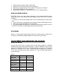
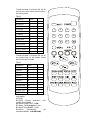
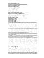
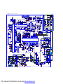
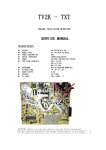
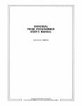
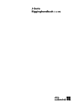
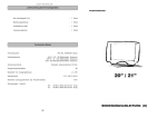
This file is provided FREE OF CHARGE from the
electromaniacs.com community
You are free to distribute this file to other persons
who needs it , but without of charge
Also on http://electromaniacs.com you can find
thousands of service manuals , schematics free of
charge
TV3K - TXT
COLOUR TELEVISION RECEIVER
SERVICE MANUAL
SECIFICATION
z
z
z
z
z
z
SYSTEM
POWER INPUT
POWER CONSUMPTION
AERIAL IMPEDANCE
TUNER
RECEIVING CHANNELS
z
z
z
z
z
PROGRAMME
PICTURE TUBE
SOUND OUTPUT
SPEAKER
AV JACKS
PAL/SECAM,B/G,I.
AC 170-245V(50/60Hz)
60W
75OHM UNVALANCED
VOLTAGE SYNTHESIZER TUNING
VHF-L E2-S6
VHF-H S7-S41
UHF E21-E69
MAX.99 PROGRAM MEMORIES
14”,20”,21”;90°
2.0W
3W 8 OHM
FULL SCART ×1
CAUTION: Before servicing the chassis, read the “Safely Precaution”.
“X -Ray radiation Precaution” and “Product Safety Notice” in this manual.
X-RAY RADIATION PRECAUTION
1. Excessive high voltage can produce potentially hazardous X-RAY RADIATION. To
Avoid such hazards the high voltage must be specified limit. The normal value of the
high voltage of this receiver is 24.5KV +/-2KV under 230V AC power source. The
high voltage must not exceed 27KV.
2. Each time a receiver requires servicing the high voltage should be checked following
the HIGH VOLTAGE CHECK procedure in this manual. It is recommended the
reading of the high voltage be recorded as a part of the service record. It is
important to use an accurate and reliable high voltage meter.
3. The primary source of X -RAY RADIATION in this TV receiver is the picture tube. For
continued X-RAY RADIATION protection, the replacement tube must be exactly the
same type tube as used in this TV receiver.
4. Some parts in this receiver have special safety-related characteristics for X-RAY
RADIATION protection. For continued safety, parts replacement should be
undertaken only after referring the PRODUCT SAFETY NOTICE below.
SAFETY PRECAUTION
WARNING: Service should not be attempted by anyone unfamiliar with the necessary
Precautions on this receiver.
The following are the necessary precautions to be observed before servicing this
chassis.
1. Since the power supply circuit of this receiver is directly connected to the AC
power line. An isolation transformer should be used during any dynamic service to
avoid possible shock hazard.
2. Always discharge the picture tube anode to the CRT conductive coating before
handling the picture tube. The picture tube is highly evacuated and if broken, glass
fragments will be violently expelled. Use shatterproof goggles and keep picture tube
away from the unprotected body while handling.
3. When replacing a chassis in the cabinet, always be certain that all the protective
devices are put back in place, such as: nonmetallic control; knobs, insulating covers,
shields, isolation resistor-capacitor, network, etc.
4. When replacing parts or circuit boards, disconnect the power cord.
5. When replacing a high voltage resistor (metal oxide resistor) on circuit hoard,
keep the resistor APP. 10mm(1/2 in.) away from circuit board.
6. Connection wires must be kept away from components with high voltage or high
temperature.
7. If any fuse in this TV receiver is blown, replace it with the FUSE specified in the
chassis parts list.
8. The receiver is designed to operate with 230V(50Hz) AC mains.
PRODUCT SAFERY NOTICE
Many electrical and mechanical parts in this chassis have special safety-related
characteristics are often passed unnoticed by a visual inspection and the X-RAY
RADIATON protection afforded by them cannot necessarily be obtained by using
replacement components rated for higher voltage. The use of substitute replacement
parts that do not have the same safety characteristics as specified in the parts list may
create shock, fire, X-RAY RADIATION or other hazards.
GENERAL ADJUSTMENT
AUTOMATIC DEGAUSSING
An automatic degaussing coil is attached around the picture tube, degaussing the tube
properly in about one second after the set is switched on. If the receiver is moved or
faced on a different direction, the power must be switched off at least 15 minutes in
order that the automatic degaussing circuit operated properly. External degaussing is
necessary if the automatic degassing proves ineffective after the set is moved.
B+ ADJUSTMENT
CAUTION: To avoid X-ray hazards and result in a nominal display width, B+ voltage
must be set in the scale of 108.0V+/-0.5V.
1.
2.
3.
4.
5.
Make sure the AC power supply is 230V, 50Hz.
Switch on the TV receiver, tune in an active channel.
Measure the voltage between C641 on Main P.C. Board by DC voltmeter.
Set contrast, brightness, color to maximum.
Adjust VR631 on Main P. C. Board for B+108.0V+/-0.5V voltage reading.
HIGH VOLTAGE CHECK
CAUTION: There is no high voltage adjustment in this chassis, B+108V voltage
directly relates to the high voltage. The high voltage does not exceed 27KV under any
conditions.
1. Connect an accurate high voltage meter to the second anode cap of the picture
tube.
2. Turn on the receiver, set brightness and contrast to minimum (Zero beam current).
3. Make sure the high voltage does not exceed 27KV.
4. NO matter whether the luminance, contrast and chrominance controls are set to
maximum or minimum, the high voltage must be kept under 27KV.
FOCUSING
Receive a TV test pattern signal; adjust controls for optimum picture. Adjust Focus
Control for a well-defined, sharpest display in the center area of the screen.
ADJUSTMENT AND SERVICING THE CHASSIS
SERVICE MODE
To enter the service mode, a special remote control which contains an additional
SERVICE key must be used. See the illustration. Press the ‘SERVICE’ key on remote
control, TV will display service menu as following table 1 line by line. To select the
parameter by using the ‘P+/P-’ keys. To adjust the selected parameter by using the
‘V+/V-’ keys. To quit the service mode, press the ‘P.P.’ key on remote control when in
the service mode.
Table 1
Parameter
Red Gain
DC Red
Green Gain
DC Green
Blue Gain
DC Blue
Apr Threshold
Logo
Value
32
063
32
063
32
063
12
6------------
To enter the table 2, press the ‘OK’ key for
the first time on the remote control when in
the service mode.
Table 2
Parameter
Tuner AGC
H position
VPOS 50
VPOS 60
VAMP 50
VAMP 60
Bright max
Bright min
Sub Tint
VCO Coarse
VCO Fine
VCO Coarse L1
VCO Fine L1
Value
22
32
10
10
47
53
63
00
32
05
063
05
080
To enter the table 3, press the ‘OK’ key for
the second time on the remote control
when in the service mode.
Table 3
Parameter
AGC gain
Option 1
Option 2
Option 3
Option 4
Option 5
ST Ttext
H POS OSD
V POS OSD
H POS TXT
V POS TXT
Value
00
48
00
06
09
00
00
001
01
057
04
Following are the items of the OPTIONS in
more details.
OPTION1:
B5=P/N/S Crystals application (0=2
crystals, 1=1 crystal)
B4=Cutoff Loop (0= OFF, 1=ON)
B3=Safety_Reset (0=Active, 1=non)
B2=Super Tuner (0=OFF, 1=ON)
B1=Sound
Demodulation
(0=
Intercarrier/MONO, 1=QSS/NICAM)
1
2
3
4
5
6
7
8
9
-/-ñ /¢
¢
ò
B0=Logo Display (0=OFF, 1=ON)
OPTION2: (It’s better to keep the default setting option2=0)
B5=Half_Contrast (0=OFF, 1=ON)
B4=Color 6db (0=OFF, 1=ON)
B3=APR Feature (0=ON, 1=OFF)
B2=Black Stretch (0=ON, 1=OFF)
B1=Auto Flesh (0=ON, 1=OFF)
B0=Coring (0=ON, 1=OFF)
OPTION3:
B5=AVL (0=OFF, 1=ON)
B4=PIF Over modulation (0=OFF, 1=ON)
B3=Market_France-SECAM L/L’ (0=OFF, 1=ON)
B2=Manual/Auto Cutoff (0=Manual, 1=Auto Cutoff)
B1=Mute pin Low/High To control the speaker (0=Low, 1=High)
B0=TDA7449/TDA7439 (0=TDA7449, 1=TDA7439)
OPTION4:
B4=SCART2 (0=OFF, 1=ON)
B3=RGB (0=OFF, 1=ON)
B2=SVHS (0=OFF, 1=ON)
B1=AV2 (0=OFF, 1=ON)
B0=AV1 (0=OFF, 1=ON)
OPTION5 and ST Ttext is for teletext setting only. It normally could not be changed. If
it’s necessary to adjust the OPTION 5, please read the following information before
adjustment.
A. For CPUs with English, French, German, Polish or English, French, German, Turkish,
Please refer to the setting as below.
1. If OPTION 5 = 00, then the TEXT languages like "ENGLISH, FRENCH, SWEDISH,
TURKISH, GERMAN, PORTUGUESE, ITALIAN, RUMANIAN " can be decoded.
2. If OPTION 5 = 02, then the TEXT languages like "POLISH, FRENCH, ESTONIAN,
CZECH, GERMAN, SERBIAN, LETTISH, RUMANIAN " can be decoded.
3. If OPTION 5 = 04, then the TEXT languages like "ENGLISH, FRENCH, SWEDISH,
CZECH, GERMAN, PORTUGUESE, LETTISH, RUMANIAN " can be decoded.
4. If OPTION 5 = 06, then the TEXT languages ENGLISH, FRENCH, SWEDISH, TURKISH,
GERMAN, PORTUGUESE, LETTISH, RUMANIAN can be decoded.
B. For coming new OTP/CPU with English, Russian, Czech, Polish, the setting of the OPTION
5 will be changed as below.
1. If OPTION 5 = 00, then the TEXT languages like "ENGLISH, FRENCH, SWEDISH,
CZECH, GERMAN, PORTUGUESE, ITALIAN, RUMANIAN " can be decoded.
2. If OPTION 5 = 02, then the TEXT languages like "ENGLISH, RUSSIAN, SWEDISH,
TURKISH, GERMAN, PORTUGUESE, ITALIAN, RUMANIAN " can be decoded.
3. If OPTION 5 = 04, then the TEXT languages like "POLISH, RUSSIAN, SWEDISH,
CZECH, GERMAN, SERBIAN, ITALIAN, RUMANIAN " can be decoded.
4. If OPTION 5 = 06, then the TEXT languages like "POLISH, RUSSIAN, SWEDISH,
CZECH, GERMAN, PORTUGUESE, ITALIAN, RUMANIAN can be decoded.
Normally, it is supposed not to set OPTION 5 = 01. If you set the OPTION 5 = 01, then the font
can be switched by press key MENU on remote control in TEXT mode for TV3K. If you set
OPTION 5 = 00, 02, 04, 06, then there is no any activity while press MENU in TEXT mode.
Please check.
A.F.C. ADJUSTMENT
Removing any R.F. signal source and prevent any stray signal source from entering
the tuner by shorting the tuner input inner contact to the out screen.
Inject the 38.9 MHZ carrier into the tuner IF output pin (pin 11).Select the parameter
‘VCO Coarse’ in the service mode (see Table 2).The ‘VCO Status…’will appear on the
screen. Then press the ‘AV’ key on remote control, the CPU will adjust automatically
until the ‘VCO Status OK’ appears on the screen. If this can not be achieved, i.e. there
is no any pattern on the screen, please adjust the T201 first until a stable pattern
appears on the screen. And then press the ‘AV’ key on remote control. The CPU will
adjust automatically once again until the ‘VCO Status OK’ appears on the screen.
GEOMETRY
To adjust the picture position and vertical size, select the appropriate parameter in the service
mode and adjust as necessary. Please see table 2.
Remote control
29
DIRECTIVTY
6m(MIN)
30
DIRECTIVTY
30°FROM LIGHT AXIS 5m(MIN)
8m(NOR
)
7m(NOR
)
OK
OK
GND
IS MARK OF CRITICAL COMPONENT; 2, SUBJECT TO CHANGE WITHOUT NOTICE.
14 INCH CRT
L101
10uH
23
WSCF
TELETEXT
34
24
R104 6K8
WSCR
WSS
33
AVDD3
JTMS
32
R103
5K6
+5VA
R102
AL1I
CVBS.TXT
R138
1K5
0.47uF 50V
C111
82PF
C105
10uF 16V
R101 5K6
C101
22pF
26
TEST0
AVDD2
31
27
MCFM
CVBS0
30
R117
10
28
JTCK
TXCF
ALOUT
+5VA
19 ALO
20 ARO
19
20
21
22
23
24
25
L209
4
C825
47P
5
3
R805
560
1uH
C219
470uF 16V
R289
10K
C281
6P8
SF201
K6257K
Z202
6.5MHz
+5V
RCA2-3
C247
0.1uF
Q632
1uF 50V
R230
75
R231
75
FBEXT
GEXT/YEXT
27
28
C226
0.1uF
L606
DEGAUSSING
D619
MTZ11C
C602
0.1uF/250VAC
R611
5K6
Q611
2SA1015Y
R619
22
XS601 XP601
1
2
T3.15A
XS600
SW602
KDCA11-WMO-P
XP600
POWER CORD
7
11
D616
1S1555
R623
2K7
R617
3K3
R626
2K7
9
R629
5M6/0.5W
GND
C653
10uF 16V
R124
2K7
C631
470pF/1KV
D631
C641
RG2
100uF 160V
T603
BCK-35-26
R635
150K
R650
18E/5W
IC604
UPC574
+33V
R642
15K
C608
1uF 50V
L600
GL100uH
R225
75
R226
75
R227
75
D641
6V2
R639
12K
R688
Q686
2SA1015Y 10K
D685
6V2
C521 4700pF 2KV
R526 22E
1
C517
680pF 500V
1N4007
D501
2
1
C511
680pF 500V
1N4007
D504
1
C516
680pF 500V
1N4007
D508
VCC1
FLYV
VP
Vout
V AMP
V.SYNC IN
R325
22K
R319
4K7
C306
220uF 35V
C327
0.1uF
C323
R334
1/0.5W
R320
2E2
R352
3K9
XP302
XS301
XP301
H-DY
1
R311
L301
C311
10K/0.5W HL105uH
2.2uF 160V
0.47uF 200V M(14")/0.33uF 200V M(20"21")
D253
1N4148
XS302
R312 1K/1W
D302 RGP15J
XS305
D305
RGP15D/1N4937
R281
100
V-DY
R326
270/0.5W
R353
12K
FLYB
IF1
11
10
R328
680
TU201
UVC2810-VEEA
C307
10uF 250V
4
XP305
R321
180K/0.5W
R399 2E2 2W(14"20")/6E8 1W(21")
1
1
T302
BSC25-3604L
IF2
C241
1n
+25V
HV
C317
470P 500V
C215
47uF 16V
R316
E47/0.5W
+5V
7
VM
D102
1N4148
R121
2K7
R122
2K7
BA
D103
1N4148
BB
C242 10uF 16V
BC
+110V
R307
1K
C243
10uF 16V
R125
4K7
C656
10uF 16V
FV
R215
4K7
C244
R216
27K
10uF 16V
SV
C304
0.1uF/M
1
D307
1N4148
22uF 50V
C309
47n/M
R306
68/0.5W
D311 1N4002
C239
47P
+25V
+15V
C629
2200PF 400VAC
PDF created with FinePrint pdfFactory Pro trial version http://www.fineprint.com
C314
10n 1K6V M(14"21")/11n 1K6V M(20")
R308
100/0.5W
C208
R687
270K
C685
1uF 50V
T301
JDT1924
Q301
2SC2383
2
R686
300K
C310
47n/M
Q302
2SD1651
C122 0.1uF/M
VT
AGC
Q685
2SC1815Y
11
D301
1N4002
22uF 16V
R324
C326
180
1000uF 25V
R330
330/1W
C333
220uF 35V
C360
47uF 160V
R689
22K
10
R323
10K
R318
D351
1N4148
R228
75
R329
3K3
R302
27/0.5W
C352
1uF 50V
Q101
2SA1015Y D105
1N4148
Q102
2SA1015Y
+5V
Vin
9
8
R333
8M2
1K8
R301
C302
39
220uF 16V
Gi
Bi
Q103
2SA1015Y
+108V
R638
27K/0.5W
Q631
2SC1815Y
VR631
2K
C654
470uF 25V
IC602 7805
7
D304 RGP15J
+5V
Vout
+8V
R351
100K
Ri
+8V
100uF 25V
C635
1000uF25V
FBi
Vin
C652
1
D635
RGP15D/1N4937
R636
8K2
R630
Vout
R647
1K/0.5W
R637
100K
2
IC603
7808
R648
10/1W
C636
0.1uF
1
5M6/0.5W
Q609
B892
C627
0.1uF
Q612
2SC3807
C617
22n/M
R120
2K7
+15V
C632 470pF/500V
10
R615 C615
22K 15n/M
F601
R631
1/1W
12
C614
0.1uF/M
+15.2V
+5VA
Vout
C633
1000uF 25V
8
6
2
XS602
C601
0.22uF/250VAC
13
5
68
D617
ES1/RGP10G
T601
ET2868
R621
120K/0.5W
Q613
2SD1710
R622
15K
R624
7805
GND
D614
1N4148
C634
680pF 500V
2
C613
4n7/M
IC601
Vin
14
R608
D606
1N4007
C604
C606
1n 1KV 1n 1KV
RT601
MZ73 K18RM270
4
12K/2W
5
D604
1N4007
R625
68/2W
C616
680pF 2KV
1
R620
120K/0.5W
2
C607
100uF 400V
D605
1N4007
GND
C603 C605
1n 1KV 1n 1KV
D603
R602 1N4007
3E9/5W
6
C300
47n/M
C325
100uF 35V
C227
0.1uF
R123
2K7
1K/0.5W
5
C305
C312
R219
470
+18V
R640
D634
RGP15D/1N4937
4
R304
150K
C324
0.1uF/M
R327
2E2
Q203
2SC1815Y
1
2
3
R303
150K
VD
R224
330K
3
TLP621
2
R300
4K7
+8V
C222
10uF 16V
R220
75
C214
22uF 16V
ICA
Q351
2SC1815Y
Z201
5.5MHz
C824
56pF
Q281
2SC1815Y
R217
1K5
B
BCL
26
C225
0.1uF
C220
1uF 50V
R218
1K5
L207
6.8UH
L201
10uH
L804
10uH
C237
1n
C217
0.1uF
1
VAMP
C235
1uF 50V
C224
+8V
C212
RCA2-1
C221
1uF 50V
C211
1n
R213
120
G
10uF 16v
C218
1uF 50V
L208
R
+8V
BC
NC
18
R212
150
XS202
GND
BOUT
17
C260
1n
C207
0.022uF
C262
C207
1n
0.022uF
C210
+8V
10uF 16V
XP202
C471
0.1UF
C470
0.1UF
VCC2
GOUT
16
C206
1uF 50V
R472
6K8
R471
6K8
POWER
ROUT
BEXT/UEXT
ICATH
Text
15
SAW
VCC2
2
MUTE
R274 47K
R263 1K
R262 1K
R264 1K
BOSD
CHR
GOSD
Y/CVBS IN3
ROSD
BS
14
R285
2K2
1
2
MUTE
IN
AROUT
B
G
R
R265 1K
R261 1K
ALI1
AL/OUT
13
XTAL3/BTUN
12
BCL/SAF
CVBS IN2
29
GND2
XTAL2
30
CVBS IN1
31
VCC2
XTAL1
X202 3.58MHz
X201 4.43MHz
4n7/M
CJPF
32
PIFLC2
33
PIFIC1 X1/VAMP/CHROUT
34
11
C261
1n
C262
1n
R470
10K
Q411
2SC1815
C264
0.1uF
35
EXT AUDIO IN
VCC1
C265
0.1uF
R468
6K8
R469
R270
56
36
CVBS OUT
GND1
C266
0.1uF
R271
56
37
IF VCC
CVBS OUT1
7K5
R269
VAMP
FB
S0
ALOTV
ARI1
AR/OUT
AROTV
L252
1uH
C263
C259
4.7uF 50V
R253 15K
R266 1K
D251 1N4148
CVBS.TXT
VS
VD
HD
FLYB
S0
AROTV
HS
R254 2K2
C271
0.1uF
38
AM/FM OUT/SC
39
10
D281
1N4148 10
C496
330pF
22K
C475
100PF
FBOSD/HC
C812 17
SRO
C811 1n 18
AV5A
10uF
VCC1
22
NC 24
RST 23
NC 25
26
NC
NC
27
NC 28
15 CAP1
14 CAP2
C810 16
SLO
10uF
ALOTV
BCL
SCL
SDA
VERT
40
9
R282
6K8
2
ALOTV
ALI1
ARI1
Gi
Bi
S-SW
Ri
FBi
VIDEO OUT
NC 29
32
GND1
NC 30
13 ARIN
GND4
SRIN
11
12 ALIN
10
21 AVCC
41
8
B892
IC615
42
7
R286 22K
29
43
6
RCA2-2
AROUT
VIDEO OUT
44
5
C201 1n
RCA1-3
45
4
3
C505
470pF
R502
100
IC301
TDA8174A
3
SF202
K9650M
IF
4
DCL 31
XOUT 33
XIN 34
SAW
C110
10uF 16V
R116 C109
15K 2n2/M
IC101
ST92195
Q282
2SC1815Y
R284
10K
2
R524
10K/2W
C495
47n/M
Q410
2SC1815
R272
56
R273
1K
2
R283
2K2
C141
0.01uF
46
C270
18pF
1
RCA1-2
VIDEO IN2
C140
0.1uF
C102
4n7/M
RCA1-1
AR1I
10
25
R200
22K
SAW2
C112
C104
220p
C117
0.22uF/M
D282
1N4148
R494
4.7
1
35
36
R504
330
Q501
BF422
R510
100
470UF/16V
10K
R492
680
C494
10uF
R512
330
C510
470pF
R523
10K/2W
R505
10K
Q502
BF423
Q504
BF422
R518
330
C515
470pF
R516
100
1K2/0.5W
R501
C497
R493
C493
10uF
HD
AGND
47
4
9
8
R514
10K
Q505
BF423
Q506
BF422
C498
22uF/25V
VIDEO IN 2
JTDO
48
5
7
R520
10K
Q507
BF423
C410
470UF/25V
6
VOL R467
10K
VIDEO IN 1
22
GND
R287
2K2
1
5
R508
4K7
+8V
R506
2K2/0.5W
+12V
IF
VDD
R290
2K2
R446
2E2/2W
C468
0.1UF
R507
47K
D503
5V6
2K2/0.5W
1K2/0.5W
R513
R515
+8V
VT
C108 21
0.1uF
C106
100uF 16V
R288
6K8
C284 1n
4
C492
1UF
R425
10K
TUNER AGC
+5VA
49
+8V
C114
4n7/M
+15V
R521
2K2/0.5W R519
1K2/0.5W
10K
Q423
2SC1815
VIDEO OUT
37
50
R268
27K
AUDIO IN
38
JTRET0
51
BSW1
PXFM
SCL
R497
10K
C469
470uF/25V
AN5265
C491
1000pF
R432
1K
R426
Q422
2SC1815
C268
C269
0.1uF/M 18pF
C253
1n
47uF 16V
SDA
20
C257
470uF 16V
C213 0.1uF
19
R428
1K
SIF IN
R105
4K7
R106
4K7
52
STV2246/2248
2SC1815
2SC1815
C113
10uF 16V
R119 5K6
C126
22pF
SCL
53
HS
R118 10 +5VA
C472
0.1uF
IF GND
C100 R137
100P 820
Q426
Q428
54
H OUT
C129
0.01uF
3
IF PLL
39
+18V
+5V
R422
6K8
S1 9
C256
0.1uF
55
SLPF
40
AVDD1
XS402
R522
10K/2W
11
S0 10
R258 56K
LFB/SSC
HSYNC
FB
2
RAGC OUT
R
C142
0.01uF
FB
IC201
XS412
1Y3
VEE
1
Q424
2SC1815
PIF IN2
VSYNC
17
18
VS
6 -E
ON/OFF
G
41
56
XS411
C205
1uF 50V
R
16
R488
100K
8.2UH
FM CAP
G
L411
1Z 13
1Y0 12
C506
100uF16V
SPEAKER
R509
100
C466
330PF
1UF
+8V
C209
0.33uF/M
R486
100K L410
8.2UH
BSW1
C248
0.1uF
C245
1n
D255
5V1 R276
1K5
R255 8K2
R259 2K2
TUNER AGC
XS410
SAW1
BSW2
SDA
C228
1uF 50V
SAW2
C107
0.1uF
B
C255
2.2uF 50V
C249
100uF 16V
C254 4n7/M
42
220
R257
1K
SCL
43
BSW1
R209
10K
R487
R485
220
XS401
C467
470UF/16V
D412
1N4148
IC412
+12V
C437
PIF IN1
BSW2
B
L202
10uH
1UF
1UF
R251 100
R252 100
NC
15
C479
C478
VT
V0L
D252
1N4148
R256
10K
9
R461
22K
R429
1K
R421
22K Q420
2SC1815
R275
D254
10K 1N4148
+5V
SAW1
8
7
6
5
14
C121
0.1uF/M
R133
33K
2Y3
5 2Y1
C474
10UF
C473
0.1UF
C422
10UF
R436
1K
SDA
44
NC
1Y1 14
8 GND
R435
1K
VCCD
45
S1(N)
13
1Y2 15
3 2Z
7
Q421
2SC1815
8
R464
4.7
C465
47n/M
Q427
2SA1015Y
AGC(P)CAP
NC
SAW_SW1
12
C420
10UF
39
10K
D413
1N4148
L401
100UH
VCC 16
2 2Y2
4
C442
1UF
7
Q503
2SA1015Y
R463
C464
10uF
Vrefif
+5VA
R801
GNDD
IC102
ST24C08
C120
0.1uF/M
C461
1000pF
AGC(S)CAP
R132
33K
AUDIO OUT
46
S0(N)
L802
22UH
6
C463
10uF
R462
680
R431
1K
R420
10K
C229
10uF 16V
1
2
3
4
NC
SAW_SW2
S0
+8V
C815
10n
AUDIO OUT
Q104
2N3904
R130
33K +33V
R131
22K
R152
22K
11
C809
10uF
10K
48
47
5
SIF IN2
49
VOL
4
SIF IN1
VOL(N)
C808
10p
AUDIO OUT
S1
3
C462
1UF
+5V
1 2Y0
C817
10uF
IC801
STV8203A
ASW3
S_SW
10
SIF IN
8
9
R111
4K7
R134
10K
S0
ALI2
6K8
+5VA
R129
+5VA
R151
4K7
ARI2
R112
NU 35
42
C115
39pF
S-SW
AV1/RGB
C116
39pF
CAP8
50
9 SLIN
51
XTAL
C802
10n
8
XTAL
DESIGN
R140
39K
220n
ON/OFF
54
7 MIN
6
7
VS OUT
6 MOUT
STDBY LED 52
AV5B
STDBY LED 53
NC
5 GND3
MUTE
C819
22p
C816
10uF
4
NC
5
X101
4M
R128
6K8
TV
3
4
C832
10uF
2
C476
0.1UF
D410
11V
C499
47UF
C831
10uF
1
C472
47UF
R460
3K3
R401
470
IC401
4052
C118 47pF
VIDEO IN3
Q106
2SC1815Y
D107
1N4148
R211
100K
220K
R803
X801 27M
C805
Q107 R110
2SC1815Y 4K7
55
NC
C804
10n
R157
10K
D108
1N4148
REST
CAP5
MUTE
R109
10K
R126
1K
LED
R135
10K
1
2
D106
R158
2K2
R411
220
R410
220
R210
100k
R404
1K
+12V
Q425
2SC1815
+18V
L213
8.2uH
C293
1n
R403
1K
R402
470
100n/M
R804
20k
KB INPUT 56
IR IN
GND2
1
C818
C820
22p
C821
10n
C822
0.1uF
+5VA
+12V
R159
3K3
ON/OFF
+5VA
R127 1K
I 3R 1
C295
1n
R830
100
SDA 36
IC103
HS0038A2
2
R831
100
Q802 2SA1015
C823
10u
P+
IC101
ST92195
+5VA
C128
22uF 16V
C293
1n
CAP7
P-
K101
R141 680
SDA
+5V
L803
22UH
OK
C291
L214 1n
8.2uH
C292
1n
C290
1n
L212
8.2uH
L211 C296
8.2uH 1n
C297
1n
V-
K102
R142 470
SCL
V+
MENU
NC 38
K103
SCL 37
K104
1K
40
K105
1K5
R143
CAP3 39
120
R144
CAP6
R115
4K7
1N4148
DV 41
R145
R146
C119
1uF 50V D100
AV
REG
270
K106
3
D101
3V9
100K
K107
2 SIF
R136
2K2
C803
10n
R147
C801 10uF
Q105
2SA1015Y
270
VIDEO IN2
+5VA
R114
470
R100
ALTERNATIVE CRTS
CRT
OUT
AR/O
VCC2
1
OUT
AL/O
3
AN5265
GND
IC411
FB
5
AR/I
GND
B/I
2
FILTER
7
4
VOL
9
AL/I
FB
11
6
MUTE
G/I
13
STATUS
FILTER
15
8
VOL
R/I
17
10
REXT/VEXT
19
12
IN
V/I
21
14
MUTE
16
VCC1
FB/I
18
ALOUT
V/O
20
AROTV
XS200
SCART
BSW2
NOTE: 1,
D310 1N4002
R310
1/0.5W
R309
R314 8K2(14")10K(20"21")
15K
+25V