1
UNIVERSAL
PROM PROGRAMMER
USER'S MANUAL
Order Number: 9800819-03
1
Copyright © 1978,1981 Intel Corporation
Intel Corporation, 3065 Bowers Avenue, Santa Clara, California 95051
I
REVISION HISTORY
REV.
DATE
11/78
-01
First Issue.
-03
Incorporates all change· packages issued against
original manual. Includes information on use of
following additional personality modules and
adapters: UPP-833, UPP-820, UPP-564, UPP-551,
UPP:..549 and UP2. Adds information on reading
8086 object files. Adds description of FILL
command.
6/81
Additional copies of this manual or other Intel literature may be obtained from:
Literature Department
Intel Corporation
3065 Bowers Avenue
Santa Clara, CA 95051
The information iri this dQcument is subject to change without notice.
Intel Corporation makes no warranty of any kind with regard to this material, including, but not limited
to, the implied warranties of merchantability and fitness for a particular purpose. Intel Corporation
assumes no responsibility for any errors that may appear in this document. Intel Corporation makes no
commitment to update nor to keep current the information contained in this document.
Intel Corporation assumes no responsibility for the use of any circuitry other than circuitry embodied in
an Intel product. No other circuit patent licenses are implied.
Intel software products are copyrighted by and shall remain the property of Intel Corporation. Use,
duplication or disclosure is subject to restrictions stated in Intel's software license, or as defined in ASPR
7-104.9(a)(9).
No part of this document may be copied or reproduced in any form or by any means without the prior
.
written consent of Intel Corporation.
The following are trademarks of Intel Corporation and its affiliates and may be used only to identify Intel
products:
BXP
CREDIT
i
ICE
iCS
im
lnsite
Intel
intet
Intelevision
lntellet
iRMX
iSBC
iSBX
Library Manager
·MCS
Megachassis
Micromainfnbe
Micromap
Multibus
Multimodule
Plug-A-Bubble
PROMPT
Promware
RMXl80
System 2000
UP.
,&:ope
and the combination of ICE, iCS. iRMX, iSBC, iSBX. MCS, or RMX and a numerical suff'lx.
ii
I A383/681!7.5K DO I
PREFACE
I
This manual describes the use of Intel's Universal PROM Programmer (UPP) with
an Intel Intellec Microprocessor Development System to create programmed readonly memories (PROMs) from data files. It is intended for use by engineers and
designers whose assignments call for the development of PROM-based systems.
While this manual is a self-contained document describing use of the UPP, several
other Intel documents may prove useful to the design engineer who uses this system
to develop microprocessor-based systems. Some of the key publications which may
be of interest are as follows:
• Universal PROM Programmer Reference Manual, Order Number 9800133
• ISIS-II Operating System User's Manual, Order Number 9800306
• Intel Data Catalog (current edition), Order Manual 10400
Notational Conventions
UPPERCASE
italics
Characters shown in uppercase must be entered in the order
shown. You can enter the characters in uppercase or lowercase.
Italics indicate variable information, such as filename or
address.
[ ]
Brackets indicate optional arguments or parameters.
{ }
Braces indicate that one and only one of the enclosed entries must
be selected. If they are also surrounded by brackets, the enclosed
items are optional.
{
}
...
Braces followed by ellipses indicate that at least one of the
enclosed items must be selected. If the field is also surrounded by
brackets, the enclosed items are optional. The items may be used
in any order unless otherwise noted.
Ellipses indicate that the preceding argument or parameter may
be repeated.
Examples of user input lines and responses are printed in white on
black to differentiate user entry from system output.
<cr>
The characters "cr" enclosed in angle brackets in examples
indicate that you should press the RETURN key. Do not enter the
angle brackets or the characters "cr."
iii
CONTENTS
CHAPTERl
GENERAL INFORMATION
PAGE
PAGE
Overview of UPP ............................ .
General Description ........................ .
System Applications ........................ .
Role in Development ........................ .
Software Types ............................ .
System Configurations ........................ .
UPM Configurations ....................... .
PPROM Configurations .................... .
Monitor Configurations ..................... .
General System Usage ....................... .
Personality Module Selection ................ .
Socket Board Replacement .................. .
Personality Module Installation .............. .
System Preparation and Initialization ......... .
Connecting UPP to Control Computer ...... .
Socket Adapter Selection and Installation .... .
Software Initiation ....................... .
Turning UPP Power On ................... .
Inserting the PROM ...................... .
Source Data Files ........................... .
I-I
1-1
1-2
1-2
1-2
1-3
1-3
1-3
1-3
1-3
1-4
1-5
1-6
1-8
1-8
2-1
2-1
2-1
2-2
2-2
2-2
2-4
2-4
2-5
CHAPTER 3
PROGRAMMING WITH MONITOR
SOFTWARE
General ......................................
Start-Up Procedure ............................
Data Input :..................................
Commands and Formats ................ _......
Program Command .........................
Transfer Command.. ... .. .. ... .. .. .•. . .... ..
Compare Command .........................
P2708 Program .............................
CHAPTERS
PERSONALITY MODULE USAGE
General ..................................... .
UPP-361 ..................' .................. .
Applicable PROMs ......................... .
Programming .............................. .
UPP-816 .................................... .
Applicable PROMs ......................... .
Adapter Requirements ...................... .
Switch Setting ............................. .
Programming .............................. .
UPP-832 .................................... .
Applicable PROMs ......................... .
Programming ..
UPP-848 .................................... .
Applicable PROMs ........................ ..
Adapter Requirement ...
Programming .....
UPP-855 and UPP-955 ....
Applicable PROMs ......
Adapter Requirement ........
Programming
UPP-865 .................
Applicable PROMs .....
Adapter Requirements ...
Switch Settings ..
Programming .....................
UPP-872 ................
Applicable PROMs ....
Programming .......
~
UPP-878 .........~
Applicable PROMs ..
Switch Settings ..
Programming
0
••••••••••••••••
0
0
0
3-1
3-1
3-1
3-2
3-2
3-3
-3-3
3-5
..................
••
0
0
0
••••••••
0
0
•••••
••••••••
0
0
•••
••
0
0.0
0
0
0
• • , • • •'
•••••
.................
0
•
0
0
•••
0
0
••
0
•
•••••
0
••
•••••••••••
0
0
0
•
•••
0
0
••••••••
.
••
••
'• •
'• • • • • • • • • • • • • • • • •
0
•••••••••
•••••••••••••••
0
•••••••••••••••••
0
•••
0
0
0
••••
••••••••••
•••••••
•••••
..
••••
0
0
0
0
4-1
4-1
••
.0
0
0
0
••••••••••••
0
CHAPTER 4
PROGRAMMING WITH UPM
SOFTWARE
........
0
0
•••••••••••
••••••••••••••••••••
0
0
0
•••••••••••••••••••••••••
00
General ......................................
UPM Software .................................
4-2
4-3
4-3
4-4
4-6
4-6
4-6
4-7
4-8
4-8
4-9
4-10
4-10
4-12
4-13
4-13
1-9
1-10
I-Ii)
1-10
1-10
CHAPTER 2
PROGRAMMING WITH PPROM
General ......................................
Program Loading .............................
Data Input ...................................
Programming .................................
Commands and Formats .......................
Program Command .........................
Transfer Command ..........................
Compare Command .........................
Monitor Call Command ......................
Commands and Formats
Program Command ........................ .
Optional Keywords and Values ............. .
Examples ............................... .
Program" Command ....................... .
Transfer Command ......................... .
Optional Keywords and Values ............. .
Examples ............................... .
Compare Command ........................ .
Optional Keywords and Values ............. .
Examples ............................... .
Compare" Command ....................... .
Read Command ............................ .
Examples ............................... .
Exit Command ............................ .
Other Commands .......................... .
0
••
,0'
0
., • • • •
0
••••
0
••••••
0
0
0
•••••••••
0
•••
0
0
0
0
0
0
••
•••
0
•
0
••••••
0
•••••••
0
••
0
•••••••
•
0
0
0
0
0
5-1
5-1
5-1
5-2
5-2
5-2
5-3
5-3
5-4
5-4
5-4
5-4
5-5
5-5
5-5
5-6
5..6
5-6
5-7
5-7
5-8
5-8
5-8
5.:8
5-9
5-9
5-9
5-10
5-10
5-10
5-11
5-11
v
CONTENTS (Cont'd.)
PAGE
UPP-820 .....................................
Applicable PROMs ..........................
Adapter Requirements .......................
Programming ...............................
UPP-833 .....................................
Applicable PROMs ..........................
Adapter Requirements .......................
Switch Settings ..............................
Programming ...............................
5-11
5-11
5-12
5-12
5-14
5-14
5-14
5-14
5-15
APPENDIX A
ERROR CODES AND CONDITIONS
APPENDIXB
UPM MEMORY ADDRESSING
TECHNIQUE
APPENDIXC
UPM COMMAND SUMMARY
TABLES
TABLE
TITLE
1-1
PAGE
PROM-Personality Module
Identification .......................
Socket Adapter Selection .............. .
PPROM Parameters ...................
Monitor Parameters ...................
1-2
2-1
3-1
1-4
1-9
2-2
3-2
TABLE
4-1
5-1
5-2
5-3
5-4
TITLE
PAGE
PROM Names Recognized by UPM
4-2
UPP-848 Switch Settings ............... 5-6
UPP-865 Device Selection ............ . . 5-8
UPP-865 Switch Settings ............... 5-9
UPP-833 Switch Settings ............... 5-14
ILLUSTRATIONSI
FIGURE
I-I
1-2
vi
TITLE
PAGE
Universal PROM Programmer Front
Panel ..........•................... 1-1
Universal PROM Programmer Interior
(Top) View ......................... 1-7
FIGURE
1-3
B-1.
TITLE
PAGE
UPP Cabling Connections . . . • . . . • • . • . .. 1-8
Sets of Data Stored in Intellec Memory .... B-1
11
CHAPTER
GENERAL INFORMATION
This chapter contains information of general interest to all users of the Intel Universal PROM Programmer (UPP) regardless of application, the system to which the
UPP is interfaced, or the type of PROM being programmed. It begins with an overview of the UPP and continues with a description of the three main types of software available with the UPP. General rules for using the system are then presented.
Chapters 2, 3, and 4 present more specific information about the use of the UPP
with each of the three main software systems with which it interfaces.
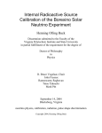
1-1. Overview of UPP
The UPP (figure 1-1) is a peripheral device used in the programming of Intel's family of electrically Programmable Read-Only Memories (PROMs). It must be used in
conjunction with a system that will be referred to herein as the control computer; this generally will be one of Intel's Intellec microcomputer development
systems, but it may be a timeshared system or a standalone processor with proper
storage configurations to interface the UPP correctly. (Refer to the Universal
PROM Programmer Reference Manual for details.)
1-2. General Description
On the front panel of the UPP are two zero-insertion-force sockets which accept the
PROM's to be programmed. A POWER ON switch and indicator, a RESET switch,
and a PROGRAMMING indicator make up the rest of the front panel. The RESET
switch is used when the control computer is unable to communicate with the UPP
and should not be used when reading or programming a PROM. The PROGRAMMING indicator lights when a PROM is being programmed.
Each of the two sockets on the front panel is controlled by a printed circuit board
(PCB) that contains all the circuits necessary to program a particular class of
PROMs. A variety of these PCBs, referred to as personality modules, is available;
each of these modules is designed for use in programming specific PROMs. Two
personality modules may be inserted into the UPP at one time, each controlling one
of the front panel sock,ets.
Figure I-I. Universal PROM Programmer Front Panel
819-1
1-1
General Information
Universal PROM Programmer
The UPP is housed in a 16- by 6- by 7-inch cabinet into which the personality
module PCBs are inserted. A control board, which supervises the operation of the
UPP, also resides in the cabinet together with the power supply.
More information about the hardware comprising the UPP is given in the Universal
PROM Programmer Reference Manual.
1-3. System Applications
The UPP is useful in several aspects of microcomputer system development. It may
be used to create a programmed PROM from a source data file stored in the Intellec.
Data to be programmed can be entered into the Intellec from paper tape or diskette,
or directly from the keyboard of an Intellec system using that particular system's
Monitor software.
The UPP also may be used to duplicate and verify the accuracy of the programmed
PROM, making it useful during the debugging of microprocessor-based systems
under development. With the Universal PROM Mapper (UPM) software described
in Chapter 4, the UPP offers additional flexibility in the formatting and
manipulating of data.
It is in the development cycle that the UPP most often is used. In the manufacturing
and field service aspects of system development and support, other equipment
specifically designed for such uses will provide better results.
The UPP can be connected directly to the following development systems:
a. Intellec Series III
b. Intellec Series II
c. Intellec 800
1..4. Role In Development
When a microprocessor-based system is in the development and design stage, the
design engineer normally uses the Intellec system to create the programs that eventually will reside in PROM, using either the microprocessor's assembly language or a
high-level language such as PL/M. Once that software has been tested, debugged,
and finalized, a PROM is created and inserted into the prototype system so that the
software can be verified in its ultimate operating environment.
It is at this stage of the development of, the microprocesso~-based system that the
UPP finds its main use. It can be used to program the prototype PROM and to
locate software errors or programming faults, as well as to create additional copies
of the prototype PROM. These copies might be kept as a historical record or used
for multiple system testing.
1-5. Software Type·s
Three types of software may be used to direct the operation of the UPP in conjunction with the control computer-UPM, PPROM, or Monitor.
UPM is available on diskette and is part of the Intel ISIS-II diskette operating
system. This software system, which is described in more detail in Chapter 4, is the
most powerful of the three available software types. In addition to the pro-
1-2
Universal PROM Programmer
General Information
gramming, data transfer, and data comparison instructions common to all three
types of software, the UPM offers a variety of other commands that allow the user
flexibility in manipulating input data being written into the PROM. These instructions are summarized in Appendix C.
PPROM is a paper tape-based software package usable with all paper tape systems,
induding the Intellec 800 and the Intellec Series II systems. PPROM, which may be
used to program all Intel PROMs, is described in detail in Chapter 2.
Monitor is a software package resident in the Intellec 800. It can be used for programming all Intel PROMs except the 2704, 2708, 8704, and 8708. The programming of these PROMs (using Monitor software) requires the use of a paper tape program known as P2708. The P2708 package may be used only to program those
PROMs that cannot be used with the standard Monitor software. The P2708
package, sup·plied with the UPP-878 Personality Module (Section 5-29), has been
superseded by the PPROM software.
1-6. System Configurations
This section describes the system configurations used to interface the UPP with each
of the three available software systems described previously. All configurations,
regardless of the software being used, require a UPP device, an Infellec system
which acts as the control computer, and a control console/input keyboard. Additional requirements for each configuration are described in the following
paragraphs.
1-7. UPM
Configur~tions
UPM requires a minimum of 32k bytes of memory, which is adequate if the PROMs
being programmed contain no more than 2k bytes; however, the memory should be
expanded to 48k bytes to accommodate PROMs containing more than 2k bytes.
Since these systems are equipped with diskette drive capability, no additional equipment is required. Where the ISIS-II diskette-based UPM system is to be used with
other control computers (e.g., Intellec 800 or Series II Model 210), a diskette drive
must be added to the basic configuration.
1-8. PPROM Configurations
All PPROM configurations require a paper tape reader in addition to the basic
equipment mentioned above. With the Intellec 800 system, 16k bytes of memory are
required. With Series II systems, the minimum memory requirement is 32k bytes.
1-9. Monitor Configurations
This software is usable only with the Intellec 800 system. It requires no additional
equipment and requires at least 16k bytes of memory.
If the P2708 software is to be used with the Monitor on an Intellec 800 system, a
paper tape reader must be added to the basic configuration. The minimum memory
requirement remains at 16k bytes.
1-10. General System Usage
This section describes those aspects of UPP usage that are applicable to all system
configurations, without regard to which personality modules are being used.
1-3
General Information
Universal PROM Programmer
1-11. Personality Module Selection
Each Intel PROM that may be programmed with the UPP requires a specific personality module. These modules consist of a PCB containing all circuitry required to
program a specific PROM or group of PROMs. Some of these modules require
special adapters, and several of these modules have on-board switches that must be
properly set. Detailed instructions on the use of each personality module are contained in Chapter 5.
Table 1-1 provides a summary of the currently available personality modules and the
PROMs with which they are associated. This table serves as a guide in selecting the
personality module appropriate to the specific PROM to be programmed by the
UPP.
Table 1-1. PROM-Personality Module Identification
PROM
Type
1602A
1702A
1702A-2
1702A-6
1702AL
1702AL-2
2704
2708
2716
2732
2732A
2758
2758 8-1865
2764
2920
3601
3602
3602A
3604
3604A
3604L-6
3604AL
3605
3605A
3608
3621
3622
3622A
3624
3624A
3625
3625A
3628
3636
4702
4702A
8702A
8702A-4
8704
8708
8741
8742
8748
8749
8751
1-4
No.
Pins
24
24
24
24
24
24
24
24
24
24
24
24
24
28
28
16
16
16
24
24
24
24
18
18
24
16
16
16
24
24
18
18
24
24
24
24
24
24
24
24
40
40
40
40
40
Organization
Personality
Module
Description
Section
256x8
256x8
250x8
256x8
256x8
256x8
512x8
1024x8
2048x8
4096x8
4096x8
1024x8
1024x8
8192x8
1152x4
256x4
512x4
512x4
515x8
512x8
512x8
512x8
1024x4
1024x4
1024x8
256x4
512x4
512x4
512x8
512x8
1024x4
1024x4
1024x8
2048x8
256x8
256x8
256x8
256x8
512x8
1024x8
1024x8
2048x8
1024x8
2048x8
4096x8
UPP-872
UPP-872
UPP-872
UPP-872
UPP-872
UPP-872
UPP-878
UPP-878
UPP-816
U PP-832 1833
UPP-833
UPP-816
UPP-816
UPP-833
UPP-820
UPP-361
UPP-865
UPP-865
UPP-865
UPP-865
UPP-865
UPP-865
UPP-865
UPP-865
UPP-865
UPP-865
UPP-865
UPP-865
UPP-865
UPP-865
UPP-865
UPP-865
UPP-865
UPP-865
UPP-872
UPP-872
UPP-872
UPP-872
UPP-878
UPP-878
UPP-848*
UPP-848
UPP-848*
UPP-848
UPP-:833
5-26
5-26
5-26
5-26
5-26
5-26
5-29
5-29
5-5
5-10/5-39
5-39
5-5
5-5
5-39
5-33
5-2
5-21
5-21
5-21
5-21
5-21
5-21
5-21
5-21
5-21
5-21
5-21
5-21
5-21
5-21
5-21
5-21
5-21
5-21
5-26
5-26
5-26
5-26
5-29
5-29
5-13
5-13
5-13
5-13
5-:39
General Information
Universal PROM Programmer
Table 1-1. PROM-Personality Module Identification (Cont'd.)
No.
Pins
Organization
8755
40
2048x8
8755A
40
2048x8
PROM
Type
*
Personality
Module
Description
Section
UPP-855 or 955* *
with UP1
UPP-8550r955**
with UP2
5-17
5-17
Adapter included.
** UPP-955 replaced UPP-855. With the use of adapter UP2, the UPP-855 can be converted
to a UPP-955.
***8051 is read-only; no programming is possible.
1-12. Socket Board Replacement
Two socket boards are available with the UPP. The UPP-501 socket board (PW A
100(419) includes a 16-pin zero-insertion-force socket in the SOCKET 1 position
and a 24-pin zero-insertion-force socket in the SOCKET 2 position. The UPP-502
socket board (PWA 1000424) includes a 24-pin zero-insertion-force socket in both
socket positions.
To change socket boards, procede as follows:
IWARNING I
Before removing the UPP's top cover panel, set the front panel ON/OFF
switch to the OFF position and remove the ac power cord from the power
source. Wait. at least 60 seconds to allow the UPP's power supply to
discharge. This will prevent possible electrical shock and protect the UPP
components.
a.
b.
c.
d.
e.
f.
g.
h.
Remove the UPP's top cover panel by twisting each of the four screw fasteners
approximately 1/4 turn counterclockwise and then lifting the cover off.
Remove the personality module PCB's (if installed) by lifting the two plastic
locking tabs on each PCB (to unseat the PCB from the mother board connector)
and raising the PCB straight up and out of the chassis.
Carefully remove the UPP's front bezel by removing the hex standoffs at the
inside top corners of the UPP. (Refer to figure 1-2.) With the standoffs
removed, pull the bezel forward from the bottom to release the two quickdisconnect fasteners which hold the bottom of the bezel to the chassis. Lay the
bezel in front of the UPP. Note that the cables between the socket board and
mother board restrict bezel travel to approximately four inches.
Disconnect the four cable assemblies at the socket board connector pin headers.
Remove the five screws that secure the socket board to the back of the bezel.
Make sure that the socket locking arms are in their up positions and then
remove the socket board.
Make sure that the protective cover on the front of the replacement socket
board is in place. (The protective cover provides electrical isolation between the
bezel and the socket board.)
With the socket locking arms in their up position, align the replacement socket
board on the bezel with the connector pin headers toward the bottom of the
bezel. Replace the five screws that secure the socket board to the bezel.
Connect the four cable assemblies to the socket board as shown in figure 1-2.
l-S
Universal PROM Programmer
General Information
Position the bezel on the chassis and push the bezel in place to seat the
quick-disconnect fasteners. Replace the hex standoffs that secure the top of the
bezel to the chassis.
j. Carefully replace the personality module PCBs into their appropriate card slots
and with the component side of each PCB facing the front of the UPP.
k. Press down on the two plastic locking tabs to seat each PCB into its
corresponding mother board connector.
1. Replace the top cover panel and secure it in place by twisting the four screw
fasteners 1/4 turn clockwise.
1.
1-13. Personality Module Installation
Since some applications require the ability to program several types of PROMs the
UPP has been designed so that the personality modules to accommodate various
PROM's may be exchanged easily.
t
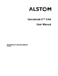
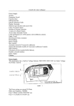
Figure 1-2 shows the interior of the UPP as viewed from the rear. Three card slots
for PCB's are provided. The card slot nearest the rear of the UPP holds the control
board, which normally is not removed except for maintenance. The card slot nearest
the front of the UPP holds the personality module that is associated with SOCKET 1
on the front panel (the 16-pin socket on the UPP-501 socket board). The center card
slot holds the personality module that is associated with SOCKET 2.
The step-by-step procedure for exchanging personality modules is as follows:
a. Set personality module on-board switch(es) if required. (Refer to appropriate
section of Chapter 5.)
iWARNINGI
Before removing the UPP's top cover panel, set the front panel
ON/OFF switch to OFF and remove the ac power cord from the
power source. Wait at least 60 seconds to allow the UPP's power
supply to discharge. This will prevent possible electrical shock and
protect the UPP components.
Remove the UPPs top cover panel by twisting the four screw fasteners
approximately 1/4 turn counterclockwise and then lifting the cover off.
c. Remove the existing personality module PCB, if installed, by lifting up its two
plastic locking tabs (to unseat the PCB from its mother board connector) and
raising the PCB straight up and out of the chassis.
d. Carefully place personality module PCB to be installed into proper card slot
with the component side of the PCB facing toward the front of the UPP.
·e. Press down on the two plastic locking tabs to seat the PCB into its
corresponding mother board connector.
f. Using a pencil, record PCB designation (e.g., UPP-872, -878, etc.) on
identification panel under appropriate socket.
b.
Use of mismatched personality module and PROM may damage
either or both components.
1-6
c
=
~.
i
"tI
~
o
3:
ORANG
"tI
~
VIEW
A-A
a9
SOCKET 2
~
MAX FASTENER
(2 PLACES)
J1
f
-=
e.
0'
.!.J
Figure 1-2, Universal PROM Programmer Interior (Top) View
~
819-2
0'
=
Universal PROM Programmer
General Information
g.
Place the top cover panel on the UPP and fasten by twisting the four screw
fasteners 1/4 turn clockwise.
To ensure proper circulation of ventilating air, the UPP never
should be operated with the top cover panel removed.
1-14. System Preparation and Initialization
With the proper personality module(s) installed in the UPP, the following additional
steps must be taken before programming a PROM:
a. Connect UPP.to control computer.
b. Determine if a socket adapter is required and install if necessary.
c. Set UPP power to ON.
d. Load and call appropriate control computer software system.
e. Install PROM(s) to be programmed.
Each of these steps is described in detail in the following subsections.
1-15. Connecting UPP to Control Computer
The UPP interfaces to the Intellec 800 and all models of the Intellec Series II with a
single cable. Figure 1-3 shows the cable connections.
Connecting the UPP to the appropriate Intellec system requires the connection of
the proper cable between the UPP rear panel receptacle and the designated receptacle on the Intellec system enclosure rear panel.
If any system other than an Intellec is used, configuration and connection must con-
form to the UPP requirements outlined in the Universal PROM Programmer
Reference Manual.
1~~~--------~~~------5~~'----------------~.~1
INTELLEC 800
SERIES II
ORSERIESIII .
[ P': I
upp
L ____
~
j! f
Figur~
1-8.
1-3. UPP Cabling Connections
819-3
Universal PROM Programmer
General Information
1-16. Socket Adapter Selection and Installation
Some PROMs-notably those with fewer or more than the number of pins for which
the sockets on the UPP front panel are designed-require the use of a socket
adapter. The type of adapter depends on the type of PROM being programmed as
summarized in table 1-2. All adapters are inserted into a 24-pin socket.
The installation procedure for any type socket adapter is as follows:
a. Select appropriate adapter for PROM to be programmed. (Refer to table 1-2.)
b. Ensure that the correct personality module PCB is installed and that it is
associated with a to 24-pin socket on the UPP's front panel.
c. Raise the locking arm of the associated socket and, if a PROM is installed in the
socket, remove the PROM.
d. Insert the socket adapter with pin 1 of the adapter aligned with the upper left
corner of the socket.
e. Secure adapter by moving socket locking arm upward until it is against the
UPP's front panel.
NOTE
Adapter must be oriented properly (with respect to pin 1) for
successful programming. If adapter is installed incorrectly, an error
message may be displayed on operator console.
~!3
The UPP-555 Adapter shorting jumper and shorting jumper block
must. be installed for some PROM types. For a 2758 PROM, a twopin shorting plug must be installed into the contacts labelled "S"
(to the left of the 2758 label on the adapter). For a 2758 S-1865
PROM, this two-pin plug must be removed. All others are "don't
care" situations.
Table 1-2. Socket Adapter Selection
Adapter
Required
Adapter
Identification Label
2758, 2758 5-1865
UPP-555
UPP-555, PWA 4601633
2764
UPP-564
UPP-564, PWA 162293
2920
UPP-820
2920, PWA 1002305
3602,3602A
UPP-562
3602/3622, PWA 1000555
3604L-6,3604AL
UPP-555
UPP-555, PWA 4601633
3605,3605A
UPP-566*
3605/3625, PWA 1000745
3608
UPP-555
UPP-555, PWA 4601633
3621
UPP-562
3602/3622, PWA 1000555
PROM
3622,3622A
UPP-562
3602/3622, PWA 1000555
3625,3625A
UPP-566*
3605/3625, PWA 1000745
3628,3636
UPP-555
UPP-555, PWA 4601633
8051,8751
UPP-551
UPP-551, PWA 162394
8742,8749
UPP-549
UPP-549, PWA 162621
8755
UP1
8755A
UP2
·UPP-566 replaces UPP-565 and programs both the A versiOn and the non-A test
version.
1-9
Universal PROM Programmer
General Information
1-17. Software Initiation
Software initiation involves loading and calling the appropriate software program to
undertake the programming of the PROM. Instructions vary slightly with the software system being used.
PPROM instructions are contained in Sections 2-1 through 2-4, Monitor instruc. tions in Section 3-1 through 3-3, and UPM instructions in Section 4-2.
1-18. Turning UPP Power On
The front panel POWER switch is used to apply power to the UPP.
To prevent possible damage to the PROM or accidental programming at
one or more memory locations, the UPP POWER switch must be ON
before the PROM is inserted into the socket or socket adapter.
1-19. Inserting the PROM
The procedure for inserting the PROM to be programmed into the front panel
socket is as follows:
a. Set UPP POWER switch to ON.
b. Ensure that the proper personality module is installed and corresponds to the
socket to be used.
c. Confirm that UPP is properly connected to control computer.
d. At the selected socket, raise the locking arm up (away from the UPP panel).
e. If a PROM is installed in the socket, remove the PROM.
f. Insert PROM to be programmed into the socket with pin 1 of the PROM
aligned with the upper left corner of the socket.
The semicircular notch on one end of the PROM must be toward
the top of the socket. Attempting to program a PROM which has
been inserted incorrectly may damage the PROM.
g.
Secure PROM in socket by moving the locking arm upward until it is against the
UPP front panel.
The PROM is now ready for programming.
1-20. Source Data Files
The data to be written into the PROM must be contained in a source data file in the
format in which the UPP expects to receive such information. (Refer to Section 4-4
and Appendix C for ways in which UPM software can be used to overcome format
problems.) These files are constructed using the Intellecsystem in accordance with
instructions given in the documentation accompanying those devices. The source
data file must be an object code file; its method of production is immaterial to the
UPP device.
The UPM Read command is the most common means of reading data from a file
into the Intellec memory. (Refer to paragraph 4-14.)
1-10
21
CHAPTER
PROGRAMMING WITH PPROM
2-1. General
PPROM is a paper tape software package (supplied with the Intellec Series II Model
210) that also can be used with other Series II and Series III systems and the Intellec
800. It can be used to program all Intel PROMs.
Before PPROM can be used to program a PROM with the UPP, the Intellec system
must be properly set up. (Refer to paragraph 1-14.)
NOTE
The POWER switch on the UPP must be set to ON prior to inserting the
PROM to be programmed. Failure to observe this precaution may cause
one or more PROM locations to be programmed accidentally.
Three steps make up the programming sequence with the UPP: (1) program loading,
(2) data input, and (3) PROM programming. The following paragraphs describe
each of these steps in detail.
2-2. Program Loading
When the Intellec system is set up and ready for use, the Intellec Monitor prints a
period (.) prompt. The following procedure loads the PPROM program into the
Intellec system for execution:
a. Place PPROM program tape into paper tape reader using instructions for the
reader.
b. Type "RO" on operator console to store PPROM into Intellec memory
locations 0100H-OFFFH.
c. When program has been loaded and monitor displays prompt".", type "G" to
call PPROM program.
NOTE
If operations with software other than PPROM are undertaken at
any point and it is necessary to return to the PPROM program, the
"G" command must carry the PPROM entry point address of 100.
In these cases, type "0100" when prompted.
d. When PPROM is ready,. an asterisk (*) prompt is displayed on the operator
console.
The system is ready to program a PROM with the PPROM software.
2-3. Data Input
Data to be programmed into the PROM must be stored in Intellec memory. It may
be placed there by any of three methods: (1) transfer from another PROM via UPP,
(2) reading from paper tape, or (3) reading from diskette file. Since only the first
method requires the use of the UPP, it is the only method described in this manual
(paragraph 2-7); the other methods are described appropriately in the Intellec
Operator's Manual and ISIS-II User's Guide.
2-1
Programming With PPROM
Universal PROM Programmer
2-4. Programming
When the PPROM program has been loaded and called and the data to be programmed into the PROM has been stored in the Intellec memory, programming the
PROM requires the following steps:
a. Turn UPP power ON.
b. Insert PROM to be programmed into proper socket.
c. Use Program command (paragraph 4-4) to program PROM.
2-5. Commands and Formats
Four commands are valid with PPROM software-Program (P), Transfer (T),
Compare (C), and Monitor Call (M). The first three commands (P, T, and C) are
used only with the UPP for PROM progamming; the last command (M) is used to
return system control to the Intellec Monitor.
All four commands are entered at the control console using the initial letter of the
desired operation (P, C, T, or M).
Each of the three PROM programming commands is followed by a string of
parameters as defined in table 2-1. This table is referenced throughout this section as
each of the PROM programming com'llands is described.
2-6. Program Command
The Program (P) command places data stored in specified Intellec memory locations
into a PROM on a designated front-panel UPP socket. (See table 2-1 for an explanation of the parameters.) The general form of this command is:
P
dat~sense
sockeLno. format [algorithm] , lo_address , hi_address, [PROM_address]
After the programming operation is complete, the PPROM software automatically
performs a Compare operation. Differences found between data stored in the
specified Intellec address locations and data programmed into the PROM are output
to the operator console. (See following examples and refer to paragraph 2-8.)
Table 2-1. PPROM Parameters
Parameter
Description
F
datIL-sense is false; bits read from memory or
PROM are complemented (i.e., O's become 1'5
and 1'5 become 0'5) before being written into
PROM or memory.
T
datIL-sense is true; bits read from memory or
PROM are unchanged (Le., 0'5 remain 0'5 and
1 's remain 1'5) when written into PROM or
memory.
sockeLno.
10r2
Number of U PP PROM socket where PROM to
be programmed or read is inserted.
format
B
Full byte at a time.
U
Upper 4-bit nibble of byte stored in InteUec
memory. Lower nibble is ignored and
unchanged in Program or Compare. In
Transfer, lower nibble bits are written as O's.
datIL-sense
2-2
Value(s)/Options(s)
Universal PROM Programmer
Programming With PPROM
Table 2-1. PPROM Parameters (Cont'd.)
Value(s)/Options(s)
Parameter
Description
L
Lower 4-bit nibble of byte stored in Intellec
Upper nibble is ignored and
m~mory.
unchanged in Program or Compare. In
Transfer, upper nibble bits are written as O's.
algorithm
Woromitted
W is used when programming 2704, 2708, 8704,
or 8708 PROM. Omit W for all others.
lo_address
hi_address
Hex values
Specifies Intellec memory locations (inclusive)
from which data to be programmed into PROM
is to be read (Program) or to which data in
PROM is to be moved (Transfer). 1o_address
must be greater than 1000H and hL_address
must be greater than 1o_address. (See notes 1
and 2.)
PROM_address
Hex or omitted
Starting PROM address where data is to be
written to or read from. If omitted, zero is
assumed. (See note 3.)
Notes
1.
When programming with "W" algorithm, hi_address minus 1o_address plus 1 must
be an even multiple of 16.
2.
If memory area between 1o_address and hi_address exceeds PROM capacity in
Transfer, data in unused Intellec memory is unaffected. Similarly, if PROM contents
exceed specified memory area, excess data in PROM is ignored.
3.
When programming with
of16.
"w"
algorithm, PROM_address must be an even multiple
Example 1
SOCKET 1 contains a 16-pin PROM to be programmed with the upper nibble of
each of the specified bytes in Intellec memory. Each bit is to be complemented prior
to programming. Data for programming is located in Intellec memory locations
lOOOH-llFFH, inclusive. Since the PROM address is to be 0, this parameter is
omitted. Enter the following at the operator's console:
: : ' '-' I ' : : : I 11 F F <C r>
*
Hi Address
Lo Address
Format (Upper Nibble)
Socket No.
Data Sense
Program Command
PPROM Prompt
Example 2
SOCKET 2 contains a 24-pin PROM to be programmed beginning at location OFFH
with the contents of Intellec memory locations lOOOH through 10FFH, inclusive.
Data is stored in fts unaltered form (Le., requires no complementing). Full-byte programming is to be used. Enter the following at the operator's console:
*
III
TT
PROM Address
Hi Address
LoAddress
Format (Full Byte)
Socket No.
DataSense
Program Command
PPROM Prompt
2-3
Universal PROM Programmer
Programming With PPROM
If, during the Compare operation following completion of the above programming
operation, the PPROM software detects a byte in error, the following message is
output to the operator's console:
COMPARE ERROR ADDR:
166
PROM=D1
RAM=D9
PROM
Location
PROM
Contents
RAM
Contents
All COMPARE ERROR messages are identical in format.
2-7. Transfer Command
The Transfer (T) command transfers data from a PROM in the designated UPP
front panel socket into the specified Intellec memory locations. (See table 2-1 for an
explanation of the parameters.) The general form of this command is:
T data_sense sockeLno. format, lo_address , hi_address, [PROM_address]
Example
SOCKET 2 contains a 24-pin PROM with data programmed in byte format. Data
need not be complemented during transfer to Intellec memory locations lOOOH11 FFH, inclusive. Enter the following command at the operator's console:
r>
* TT2B,1000,11FF<c
T --,--
IIII_________-_
L . . . -_
_
-
__
1-------------
Hi Address
LoAddress
Format (Full Byte)
Socket No.
Data Sense
Transfer Command
PPROM Prompt
2-8. Compare Command
The Compare (C) command reads data from a PROM inserted in one of the two
front panel sockets on the UPP and compares it to data read from the specified
Intellec memory locations. Differences are listed at the operator's console. (See table
2-1 for an explanation of the parameters.) The general form of this command is:
C data_sense socket_no. format, lo_address , hi_address, [PROM_address]
Example
SOCKET 2 contains a 24-pin PROM with data programmed in byte format. Its contents are to be compared with the contents of Intellec memory locations 4000H43FFH, inclusive. Data is not complemented in the PROM. Since the starting
PROM address is 0, this parameter is omitted. Enter the following command at the
operator's console:
* CT2B,4000,43~F<cr>
T --r=
IIIII
-
1 - - - - -
Hi Address
LoAddress
~:~~:: ~o~" Byte)
.
Data Sense
....- - - - - - - - - - - - Compare Command
PPROM Prompt
1-------------2-4
Programming With PPROM
Universal PROM Programmer
Assuming the contents of lntellec memory location 4300H do not match the contents of the corresponding PROM location, the following message will be output to
the operator's console:
COMPARE ERROR ADDR:
-
300
PROM
Location
PROM=D9
RAM=FF
--.,...--'
PROM
Contents
RAM
Contents
2-9. Monitor Call Command
The Monitor Call (M) command returns control of the Intellec system to the
Monitor. Typically, this command is used when PROM programming is complete,
but it also may be used to return control to the Monitor to permit more data to be
read into the Intellec memory or for any other reason in which Monitor control is
desired.
2-5
I
•
CHAPTER 3
PROGRAMMING WITH
MONITOR SOFTWARE
n
I
3-1. General
The Monitor software package, which is resident in the Intellec 800, includes PROM
programming capability that can be used to program all Intel PROMs except the
2704, 2708, 8704, and 8708 devices. These four PROMs require use of the PPROM,
UPM, or the P2708 Monitor supplement described in paragraph 3-8.
Since the Monitor is system-resident, it requires no loading or calling procedure such
as those used to implement PPROM and UPM software. Before a PROM can be
programmed, the Intellec 800 system must be properly set up and the PROM must
be inserted in a connected UPP device.
NOTE
The POWER switch on the UPP must be set to ON before inserting the
PROM to be programmed. Failure to observe this precaution may cause
one or more PROM locations to be programmed accidentally.
The start-up procedure for the Intellec 800 system is described in Section 3-2, data
input methods are discussed in Section 3-3, and general programming techniques
and parameters are outlined in Section 3-4.
3-2. Start-Up Procedure
If the lntellec 800 system has been powered off or is being installed as a new device,
a "cold start" or "bootstrap" must be performed before the Monitor software can
be used. The procedure for this start-up is as follows:
a.
Turn on Intellec 800 system power by inserting key in power switch and turning
key clockwise.
b.
Press top of BOOT rocker switch.
c.
Press top of RESET rocker switch.
d. Enter a space on operator console.
e. System responds with the following (or similar) message indicating Monitor is
ready to run:
MOS MONITOR, Vx.y
f.
Press bottom of BOOT switch.
g.
System displays Monitor prompt (.).
The Intellec 800 system now is ready to accept the first command.
3-3. Data Input
Data to be programmed into the PROM must be stored in Intellec memory. It may
be placed there by any of three methods: (1) transfer from another PROM via UPP,
(2) reading from paper tape, or (3) reading from an ISIS-II (diskette) file.
Since only the first method requires the use of the UPP, it is the only method
described in this manual (paragraph 3-6). The others are described appropriately in
the InteJlec System Operator's Manual and the ISIS-II User's Guide.
3-1
Universal PROM Prc:>grammer
Programming With Monitor Software
3-4. Commands and Formats
Three Monitor commands are used exclusively with the UPP device-Program (P),
Transfer (T). and Compare (C). Each of these commands has an associated string of
parameters including some or all of those shown in table 3-1. The table should be
referred to throughout the discussion of these three commands in paragraphs 3-5
through 3-7.
Each Monitor command is entered by keying the first character of the command
name (i.e., P for Program, T for Transfer, or C for Compare) followed by the
string of appropriate parameters.
Table 3-1. Monitor Parameters
Parameter
Value(s)/Options(s)
Description
F
data_sense is false; bits read from memory or
PROM are complemented (Le., O's become 1's
and 1's become O's) before being written into
PROM or memory.
T
data_sense is true; bits read from memory or
PROM are unchanged (ie., O's remain O's and 1's
remain 1's) when written into PROM or memory.
X
SOCKET 2 (24 pins).
Y
SOCKET 1. If SOCKET 1 has 24 pins, this option is
used interchangeably with Z in Program (P) and
Transfer (T). To Compare (C) from 24-pin SOCKET
1, both Y and Z must be used in separate operations.lf SOCKET 1 has 16 pins, Y selects upper
nibble of byte (bits 4-7).
Z
SOCKET 1. Same as Y, except if SOCKET 1 has 16
pins, Z selects lower nibble of byte (bits 0-3).
la_address
hi_address
Hex Values
Specify Intellec memory locations (inclusive)
from which data to be programmed into PROM is
to be read (Program) or to which data in PROM is
to be moved (Transfer). la_address must be
greater than 100H and hi_address must be
greater than la_address. (See Note 1.)
PROM_address
Hex Value
Location in PROM where specified operation is to
begin.
data_sense
sockeLoption
Note:
1.
if memory area between la_address and hi_address exceeds PROM capability in
Transfer, data in unused Intellec memory is unaffected. Similarly, if PROM contents
exceed specified memory area, excess data in PROM is ignored.
3-5. Program Command
The Program (P) command places the data contained in Intellec memory locations
defined by Hi Address and Lo Address, inclusive, into a PROM inserted in the
designated UPP front panel socket. The general form of this command is:
P
dat~sense
sockeLoption lo_address, hi_address, PROM_address
Programming With Monitor Software
Universal PROM Programmer
As each byte is programmed into the PROM, the Intellec system reads the byte and
compares it with the same byte in the Intellec memory. If an error occurs because
one or more bits do not program correctly, the Monitor stops the Program operation and outputs an error message to the operator's console followed by the Monitor
"error prompt", an asterisk (*).
Example 1
SOCKET 1 contains a 16-pin PROM to be programmed in 4-bit nibbles. Each byte is
complemented prior to programming. Data to be programmed is contained in the
upper nibble in Intellec memory locations lOOH-lFFH; it is to be written into the
PROM starting at address O. Enter the following command at the operator console:
PFY100,1FF,O<cr>
T - - - HiPROM
Address
Address
1..
_______
1111
1..-----------
1..-----------
Lo Address
Socket Option
Data Sense
Program Command
Monitor Prompt
Example 2
If a programming error occurs at PROM address IFOH, the error message will be:
1 F0 *
3-6. Transfer Command
The Transfer (T) command reads data from the PROM inserted in the designated
UPP front panel socket into the specified Intellec memory locations. The general
form of this command is:
Example
SOCKET 2 contains a 24-pin PROM with data in 8-bit bytes. This data, in its
uncomplemented form, is to be transferred to Intellec memory locations lOOHIFFH, inclusive. Enter the following command at the operator console:
TTX100,1FF<cr)
T .,.....
.
.
11
.
11
Hi Address
..- - - - - - - - Lo Address
Socket Option
Data Sense
Transfer Command
Monitor Prompt
1..----------3-7. Compare Command
The Compare (C) command reads data from the PROM inserted in the designated
UPP front panel socket and compares it, byte-for-byte, with the data stored in the
specified Intellec memory locations. The general form of this command is:
C data_sense sockeLoption lo_address, hi_address
3-3
Programming With Monitor Software
Universal PROM Programmer
Differences between the two sets of data are displayed on the operator console in the
following format:
Intellec_memory_location Intellec_contents PROM_contents
The following examples demonstrate the use of the Compare command and show
how a difference between the PROM contents and the Intellec memory contents is
reported.
Example 1
SOCKET 2 contains a PROM whose contents are to be compared with the contents
of Intellec memory locations 4000H-43FFH, inclusive; the data is complemented.
Enter the following command at the operator's console:
CFX4000,43FF<cr>
--r=
T
Hi Address
...- - - - - - - - Lo Address
Socket Option
.
Data Sense
Compare Command
. . . - . - - - - - - - - - - Monitor Prompt
IIII
During the Compare operation, a difference between the contents of Intellec
memory location 4300 and the corresponding PROM location is detected. The
system displays the following message:
4300 FO 01
1
T. ._-,-_______
-
PROM location contents
Intellec memory contents
Intellec memory location
Example 2
The contents of a PROM in SOCKET 1 are to be compared with the contents of
Intellec memory locations 4000H-43FFH, inclusive; data is uncomplemented. Since
SOCKET 1 Compare operations always take place in 4-bit nibbles, the first of two
commands must be entered at the operator console as follows:
CTY4000,43FF<cr>
IIII
T
-,-~ Hi Address
1--------- Lo Address
.
1------------
Socket Option (low nibble)
Data Sense
Compare Command
Monitor Prompt
The above command will accomplish the comparison of the low-order bits (bits 0-3)
of each PROM location with the corresponding low-order bits in Intellec memory.
On completion of that Compare operation, the second command must be entered at
the operator console to complete the comparison:
CT Z4000,43FF<cr>
IIII
T -,-Hi Address
1--------- Lo Address
Socket Option (high nibble)
Data Sense
Compare Command
. . . - . - - - - - - - - - - Monitor Prompt
-
3-4
Universal PROM Programmer
Programming With Monitor Software
3-8. P2708 Program
The P2708 program is a supplementary software package used with Monitor to program the Intel 2704, 2708, 8704, and 8708 Erasable PROMs (EPROMs). The P2708
package is not a recommended software package, since all functions of the P2708
software are performed by the UPM and PPROM software. For this reason, data in
this section is supplied for reference only.
Operationally, there are two differences between P2708 and Monitor PROM programming techniques. First, the P2708 is not system-resident and therefore must be
loaded from paper tape before it can be used. The procedure for loading and executing P2708 is described below. Second, the four PROMs that may be programmed with the P2708 package require the programming to begin at PROM
address O. As a result, no PROM address need be specified in using P2708.
There is one other difference that is not a function of P2708, but rather of the
PROMs with which it is used. All four of the PROMs that can be programmed with
this package are 24-pin devices with 8-bit bytes. This means that SOCKET 1 cannot
be used with P2708 if it is a 16-pin socket and also that the Y and Z socket options
have identical meanings rather than different uses depending on the size of the
socket installed as is the case with Monitor software.
In every other respect, P2708 is identical to Monitor software. Examples and
descriptions of command formats provided in paragraph 3-7 apply to P2708 in every
respect except those described above.
The procedure for loading the P2708 software from paper tape into the Intellec
system is as follows:
Ensure Monitor system is operational and prompt character (.) appears on
operator console.
b. Place P2708 program tape into paper tape reader, following instructions for
reader.
c. Enter Intellec Monitor READ command as follows:
a.
d. This initiates reading the P2708 software into memory. When reading is
complete, use Monitor G command to call P2708 as follows (P2708 reads into
Intellec memory beginning at location 20H.)
e.
When the P2708 software is loaded, the P2708 prompt character (:) appears on
operator console. PROM programming may begin.
All three Monitor PROM programming commands (Program, Transfer, and Compare) described in paragraphs 3-5 through 3-7 are used with P2708 software exactly
as with Monitor software with the exception of the different prompt character and
the omission of PROM Address. Socket options Y and Z, as indicated, have identical meanings with P2708.
3-5
CHAPTER 4
PROGRAMMING WITH UPM SOFTWARE
4-1. General
The Universal PROM Mapper (UPM) software system is used with an Intellec
development system to program all Intel PROMs. The UPM command set consists
of 16 instructions, as opposed to the three-command structure of the other two software systems described in this manual. Aside from the Program, Transfer, and
Compare commands available with all three types of PROM programming software, UPM offers a range of instructions which may be used to alter and reformat
data during programming and data transfer or compare operations.
Discussion of the UPM software is contained in two places in this manual. In this
section, the main commands used in most applications are described. In Appendix
C, the other 10 commands, which are used less frequently, are provided in summary
form. Most PROM programming applications rarely use these 10 commands (if at
all), and the UPM user need not be concerned with a detailed understanding of their
use. A review of Appendix C (and reference to it when a specific command is needed
to meet a requirement) will provide the user with sufficient information to allow
proper use of the UPM's flexibility.
All addresses used in the commands in this chapter are referred to as "logical word
positions." The relationship between this logical address space and the actual
Intellec memory address is explained in Appendix B.
In this section, the available UPM software is described and procedures for loading
it are outlined. Then, the general format for UPM commands is described before the
Program, Program", Transfer, Compare, Read, and Exit commands are discussed
individually. Finally, an introduction to the remaining 10 instructions is provided in
paragraph 4-16.
4-2. UPM Software
UPM is available in a diskette-based system that operates under control of the ISISII operating system. The diskette-based version of UPM operates under control of
the ISIS-II Diskette Operating System. The procedure for loading this version of
UPM is as follows:
a.
Ensure Intellec system is properly configured and operational. ISIS prompt
character (-) will be displayed at operator console.
b. Instruct ISIS-II to load and execute UPM by entering command as follows:
c.
UPM will respond by displaying-following message:
I S I S- I I PROM MAPPER Vx.y
TYPE*
The type (number) of the PROM to be programmed now must be entered. Refer to
table 4-1 for valid names.
4-1
Universal PROM Programmer
Programming With UPM Software
Table 4-1. PROM Names Recognized by UPM
Name
Type
Note
=
1702A
2704
2708
2716
2732
2732A
2758
2764
3601
3602
3602A
3604
3604A
3604L
3605
3608
3621
3621 A
3622
3622A
3624
3624A
3625
3628
3636
4702A
8702A
8708
8741
8748
8755
Use also for 1702 and 1602A
Use also for 8704
Use also for 27588-1865
Use also for 3604AL
Use also for 3605A
Use also for 3625A
Use also for 4702
Use also for 8742
Use also for 8051, 8751, and 8749
Use also for 8755A
For any PROM with a dash number (different speed or power), do not enter '-xx'. For any
Mxxxx (Mil-spec parts), do not enter the M.
4-3. Commands and Formats
"
UPM commands entered at the operator console are made up of a command name
with additional values, words, parameters, and keywords depending on the command being used. Some of the parameters used with UPM commands may be
entered as separate command lines rather than as part of the command string itself.
The command name must be entered using enough letters to make the name unique
(e.g~, PRO for PROGRAM, COM for COMPARE, etc.). If desired, the entire command name may be spelled out; if this is done, it must be spelled correctly.
Keywords and values that specify parameters to be used with a command may be
entered in any order. They are separated from one another by a space, an equal sign,
or a comma, as appropriate. The specific delimiter is defined during the discussion
of the commands in this section and in Appendix C.
All UPM commands end with a carriage return (not shown in the examples and
descriptions in this manual). If it is necessary to continue a command to a second
line, type an ampersand (&) at the end of the line to be continued, then enter a carriage return. The system will display two asterisks as the continuation prompt and
the command may be continued at that point.
Line continuation is sometimes necessary because of the system's 128-character
limitation on display lines. (If this limit is exceeded, the error message LINE TOO
LONG is displayed and the line being entered is discarded. It then must be completely reentered.) No command may exceed 256 characters. The ampersand
4-2
Universal PROM Programmer
Programming With UPM Software
character, if used, must be the last non-blank character on the line or it will not have
the desired result. The carriage return following the "&" will not serve as a
separator; a space or a comma must be used at the the start of the next line. A space
or blank must precede "&"; if the command permits a ",", this character may
precede the "&".
Numbers to be entered as parameters with UPM software may be entered in
decimal, hexadecimal, octal, or binary. All numbers must be positive integers in the
range O-OFFFF (hexadecimal). This means the largest number that may be used is
65,535 decimal. Larger numbers, if entered, will be evaluated modulo 10000H. The
suffix used with a number determines the number system to be used in evaluating it.
Decimal numbers may use a D suffix or the suffix may be omitted, in which case
decimal is assumed. Hexadecimal numbers use the suffix H and must begin with a
digit. Octal numbers must use the suffix letters 0 or Q. Binary numbers are
indicated with the suffix B. Leading zeros entered with any number are ignored,
although a leading zero may be required in hexadecimal entries (e.g., FFH is not
allowed as a number, but OFFH is a valid number).
The remainder of this section is devoted to a description of the Program, Program",
Transfer, Compare, Read and Exit commands.
4-4. Program Command
The Program (PRO) command requires three keywords: FROM, TO, and START.
The general form of the command is as follows:
PROGRAM FROM loaddress TO hiaddress START PROM address
The 10 address specifies the starting logical word position where the data is stored.
The hi address is the last logical word position containing this data. The PROM
address is the starting location in the PROM where the data is to be placed. (See
Appendix for the effect of the use of an OFFSET address on this command.)
a
The keywords FROM, TO, and START must be used as indicated. These keywords
function as a signal to UPM that the next number provides the starting, ending, or
PROM addresses, respectively.
To save keystrokes-or to prevent a command line from exceeding either the 128character display line limit or the 256-character command line limit-it is possible to
enter the command using unique abbreviations of each command and keyword, providing the following alternate form for the Program command:
PRO FROio address TO hi address ST A PROM address
4-5. Optional Keywords and Values
Besides the three required keywords associated with the Program command, any of
four others may be included within the command line. These optional keywords are
described briefly in this section; they are more fully explained in Appendix C.
The socket number may be specified using the general form:
SOC KET number
This is not necessary if the socket number previously has been specified by a separate
SOCKET keyword on another command line preceding the Program command and
need not be changed.
4-3
Universal PROM Programmer
Programming With UPM Software
Similarly, the data sense of the memory-to-PROM transfer may be specified using
the DATA keyword with the following general form:
DATA sense
Here, sense is a T if data is uncomplemented, and F if it is complemented.
An address offset may be specified using the OFFSET keyword with the following
general form:
OFF SET address
If a previously specified offset is correct, the OFFSET keyword is not required. If,
however, this offset must be altered for this Program command, it must be provided
in the Program command line or in a preceding line of its own. Appendix B contains
a detailed explanation of the OFFSET keyword and its usage.
Some of the flexibility of the UPM software lies in its ability to enable extensive data
manipulation during programming operations. These functions are specified using
Format commands during the programming process. If a format has been defined,
the FORMAT keyword may be included in the Program command line to instruct
UPM to use the format previously specified. In the Program command, this
keyword stands alone, requiring no value associated with it. The Format command
and concept are explained in Appendix C.
4-6. Examples
A minimum Program command requires the presence of starting and ending
addresses in Intellec memory where the data to be programmed into the PROM is
stored and the starting PROM address where it is to be programmed.
Example 1
A PROM plugged into SOCKET I is to be programmed with 256 (decimal) bytes
from logical word positions 0-255. Data is to be placed in the first 256 locations of
the PROM. Enter the following command at the operator console:
* PROGRAM FROM 0 TO 255 START O<cr>
T
PROM Address
Hi Address
.....- - - - - - - - - - - Lo Address
...- - - - - - - - - - - - - - - - - Program Command
UPM Prompt
I
1...-.------------------I
Example 2
Assuming the data in Example 1 is stored in Intellec memory locations 7700H77FFH, two methods could be used to cause the programming to occur. In the first
instance, the exact -Intellec memory addresses could be used as follows (assuming
OFFSET=O):
* PRO
FRO 7700H TO 77FFH STA O<c r >
T
T
PROM Address
~
1...-.---------- HiLoAddress
Address
" ....
~ -~---------------- Program Command
.....- - - - - - - - - - - - - - - - - - - - - UPM Prompt
I
4-4
Programming With UPM"Software
Universal PROM Programmer
Alternatively, an offset of 7700H could be specified and the numbers 0 and 255
(decimal) used as the starting and ending Intellec memory addresses as follows:
* PRO FRO 0 TO 255 STA 0 OFF 7700H<cr>
~
IT
T
Offset Address
' - - - - - - - - - - - PROM Address
Hi Address
- - - - - - - - - - - - - - - - - - - Lo Address
1 . . . . . - - - - - - Program Command
....- - - - - - - - - - - - - - - - - - - - - UPM Prompt
The OFFSET keyword may be specified on a separate line before the Program command as follows:
* OFFSET = 7700H<cr>
* PROGRAM FROM 0 to 255 START O<cr>
This sequence would have the same effect as the second alternative shown above.
Example 3
If it is desired to place the data stored in logical word positions 0-255 into two
PROM's installed in the two UPP front-panel sockets with no alteration of data,
this may be accomplished by specifying the SOCKET option in the second of two
Program commands as follows:
* PROGRAM FROM
0 TO 255 START O<cr>
T
PROM Address
Hi Address
......- - - - - - - - - - - - - Lo Address
~----------------- Program Command
......- - - - - - - - - - - - - - - - - - - - - UPM Prompt
I I
This command programs the first PROM (in the socket specified earlier by a
SOCKET keyword on a separate line or the system default SOCKET 1). In this case,
assume SOCKET 1 has been specified earlier. To place the same data in the PROM
in SOCKET 2, enter the following command at the operator console:
* PROGRAM FROM
I I
0 TO 255 START 0 SOCKET 2<cr>
T
Socket Number
PROM Address
Hi Address
Lo Address
Program Command
UPM Prompt
As with the OFFSET keyword in Example 2, it is possible to change the socket
number by using a SOCKET keyword on a separate line before the Program command as follows:
* SOCKET=2<c r>
* PROGRAM FROM
0 to 255 START O<c r>
4-5
Programming With UPM Software
Universal PROM Programmer
4-7. Program" Command
This command is a variation of the Program command and enables the user to program a series of PROMs with the same data, format, offset address, and other
parameters as the preceding Program command. Thus, to program several PROMs
enter the full Program _command with all keywords and values discussed above,
program the first PROM, unplug the programmed PROM, substitute the unprogrammed PROM, then enter the Program" command.
NOTE
This command will not be accepted by UPM if any of the keywords or
parameters have been changed since the last Program command was
entered. The data contents of Intellec memory may, however, be altered
between the first Program command and the Program" command by
means of the Change command. (Refer to Appendix C.)
Example
Three PROMs are to be programmed with the contents of logical word positions
0-255 (decimal). Programming is to begin at PROM address o. Enter the following
commands at the operator console:
* PROGRAM
* PROGRAM
* PROGRAM
FROM 0 TO 255 START O<cr>
I/<cr>
I/<cr>
Removal of the programmed PROM and the insertion of the unprogrammed PROM
must be accomplished between the above instructions.
4-8. Transfer Command
The Transfer command requires two keywords to specify the starting and ending
logical word positions where data is to be stored (read) from the PROM. The
minimum command has the following general form:
T RAN SFER FRO M 10 address TO hi address
The command reads data from the PROM previously selected by a SOCKET keyword into the specified logical word positions. Reading begins at PROM address o.
4-9. Optional Keywords and Values
Besides the two required keywords associated with the Transfer command, any of
four other keywords may be included within the command. line. These optional
keywords are described briefly in this section; they are explained more fully in
Appendix C.
The address of the first location in the selected PROM containing the data to be
transferred can be specified using the general form:
STAR T PROM address
4-6
Programming With UPM Software
Universal PROM Programmer
The Transfer command fills the memory locations starting at 10 address through hi
address, inclusive, with PROM data starting at the location in the PROM specified
by PROM address.
The socket number may be specified using the general form:
SOCKET number
This is not necessary if the socket number previously has been specified by a separate
SOCKET keyword on another command line preceding the Transfer command and
need not be changed.
Similarly, the data sense of the PROM-to-memory transfer may be specified using
the DATA keyword with the following general form:
DATA sense
Here, sense is a T if data is uncomplement~d, and F if it is complemented.
An address offset may be specified using the OFFSET keyword with the following
general form:
OFF SET address
If a previously specified offset is correct, the OFFSET keyword is not required. If,
however, this offset must be altered for this Transfer command, it must be provided
in the Transfer command line or in a preceding line of its own.
Some of the flexibility of the UPM software lies in its ability to allow extensive data
manipulation during transfer operations. These functions are specified using Format commands. If a format has been defined, the FORMAT keyword may be
included in the Transfer command line to instruct UPM to use the format previously
specified. In the Transfer command, this keyword stands alone and requires no
associated value. The Format command and concept are explained in Appendix C.
4-10. Examples
Two examples of the use of the Transfer command are provided and described in
this section.
Example 1
Data from a PROM that has been inserted into a previously defined UPP front
panel socket is to be moved to logical word positions 0-255. Enter the following
command at the operator console:
1...-_ _ _
Hi Address
' - - - - - - - - Lo Address
.....- - - - - - - - - - - - Transfer Command
.....- - - - - - - - - - - - - - UPM Prompt
4-7
Universal PROM Programmer
Programming With UPM Software
Example 2
In this example, the contents of two separate PROMs will be read into contiguous
memory locations in the Intellec memory. This is often a requirement where the contents of two PROMs are to be moved into a single, larger PROM. Enter the following commands at the operator console:
* TRANSFER FROM a TO 255<cr>
Hi Address
' - - - - - - - - - - - - - - lo Address
' - - - - - - - - - - - - - - - - - - - - Transfer Command
.....- - - - - - - - - - - - - - - - - - - - - UPM Prompt
* TRANSFER FROM 256 TO 511 SOCKET 2<cr>
1---- Socket Number
T
T
10...-_ _ _ _ _ _ _ _ _ _ _ _ _ _ _ _ _ _
10...-_ _ _ _ _ _ _ _ _ _ _ _ _ _ _ _ _ _ _ _ _
Hi Address
loAddress
Transfer Command
UPM Prompt
At the conclusion of the second transfer operation, the contents of the two PROMs
will be stored in logical word positions 0-511 (decimal).
4-11. Compare Command
The Compare command requires two keywords to specify the starting and ending
Intellec memory addresses where data to be compared with the PROM contents is
stored. The general form of the command is as follows:
COMPARE FROM loaddress TO hiaddress
This command reads data from the PROM, beginning at address 0, one byte at a
time, and compares each byte with the contents of the corresponding logical word
position. Comparison discrepancies are displayed on the operator console in the
following format:
# PROM address M= memory contents PRO M= PROM contents
4-12. Optional Keywords and Values
Besides the two required keywords associated with the Compare command, any of
three others may be included within the command line. These optional keywords are
described briefly in this section; they are explained more fully in Appendix C.
The socket number may be specified using. the general form:
SOCKET number
This is not necessary if the correct socket number has been previously specified by a
separate SOCKET keyword on another command line preceding the Compare
command.
Similarly, the data sense of the compare operation may be specified using the DATA
keyword with the following general form:
DATA sense
Here, sense is a T if data is uncomplemented, and F if it is complemented.
4-8
Programming With UPM Software
Universal PROM Programmer
An address offset may be specified using the OFFSET keyword with the following
general form:
OFF SET address
If a previously specified offset is correct, the OFFSET keyword is not required. If,
however, this offset must be altered for this Compare command, it must be provided
in the Compare command line or in a preceding line of its own.
The FORMAT keyword may be used after the hi address to cause the Compare
command to be executed under the current Format as explained in section C-4.
Data read from the PROM may begin at a location other than address
ing address for the PROM may be specified using the general form:
o. The start-
STAR T PROM address
4-13. Examples
Two examples of the use of the Compare command in UPM are provided in this
section.
Example 1
A PROM previously specified as being in SOCKET 1 contains programmed data
which is to be compared with the contents of logical word positions 700H-SFFH.
Enter the following command at the operator console:
* COMPARE FROM 700H TO 8FFH<cr>
_
T
_______________
Hi Address
Lo Address
Compare Command
- - - - - - - - - - - - - - - - - - UPM Prompt
Example 2
Two types of PROM's have been used to store the same data (perhaps as a test of the
reliability or usefulness of the two types in comparison with one another). To compare the contents of the PROM in SOCKET 1, assuming this socket has been
previously specified, enter the following command at the operator console:
* COMPARE FROM 0 TO 255<cr>
Hi Address
- - - - - - - - - - - Lo Address
" - - - - - - - - - - - - - - - - Compare Command
- - - - - - - - - - - - - - - - - - - UPM Prompt
Assume the data in the second PROM-inserted in SOCKET 2-is complemented.
To carry out a comparison of the same data as used in the above case with the contents of the second PROM, enter the following command at the operator console:
* COMPARE
'---
FROM 0 TO 255 SOCKET 2 DATA F<cr>
T
Data Sense
" - - - - - - - Socket Number
Hi Address
......- - - - - - - - - - - - - - Lo Address
- - - - - - - - - - - - Compare Command
...- - - - - - - - - - - - - - - - - - - - - - UPM Prompt
II
4-9
Programming With UPM Software
Universal PROM Programmer
Example 3
A PROM previously specified as being in SOCKET 1 contains programmed data in
locations lOOH-lFFH which is to be compared with the contents of logical positions
600H-6FFH. Format control is also to be specified. Enter the following command at
the operator console:
* COMPARE
FROM 6:2 J
-:
6;~~
TT
;ORMAT START 100H<c r >
-r=
PROM Address
.......- - - - - Required START keyword
_ _ _ _ _ _ _ _ _ _ _ _ Format specification
...
Hi Address
LoAddress
.......- - - - - - - - - - - - - - - - - - - - - - Compare Command
.......- - - - - - - - - - - - - - - - - - - - - - - - UPM Prompt
4-14. COMPARE" Command
This command is a variation of the Compare command and enables the user to compare a series of PROMs with the same data, format, offset address, and other
parameters as the preceding Compare command. To compare several PROMs, enter
the full Compare command with all the appropriate keywords and values described
in the Compare command. Compare the first PROM, unplugtbe compared PROM,
plug in the next PROM to be compared, then enter the Compare" command.
NOTE
This form of the Compare command cannot be used if the format or any of the
parameters have been changed since the last Compare command. A new
specification of the parameters for the Compare command is required.
Example
Three PROMs are to be compared with the contents of logical word positions 0-255
(decimal). Comparing is to begin at PROM address 200 (decimal). Enter the following commands at the operator console:
* COMPARE
SOCKE~
*1"';".1;'
aii
•
~~:~
: TJ 255 START 200<cr>
Removal of the compared PROM and the insertion of the uncompared PROM must
be accomplished between the above commands.
4-15. Read Command
This command is· used to read data from a diskette file into Intellec memory. The
Read command has two forms. The general format for the first form is as follows:
REA 0 file type FI LE file name [ I NT 0 bias] [U NTIL stop address]
file name is an ISIS file name and can be :HR: for the high-speed tape reader. file
type is a keyword specifying the format of the data in that file. Its value is HEX for
HEX-ASCII format (default if keyword is omitted), 86HEX for 8086 HEX-ASCII
format, BNPF for that format, or OBJECT for 8080 or 8086 object file format.
4-10
Universal PROM Programmer
Programming With UPM Software
'INTO bias' is optional, as denoted by the enclosing brackets ([]).
Data is loaded into memory as specified by the load address information contained
in the file. For BNPF format, which has no load address information, loading
begins at O. bias is a constant value which is simply added to each load address to
form a new address where data is to be loaded. Of course, all addresses are modified
by the value of the OFFSET keyword as described in Appendix B.
'UNTIL stop address' is only used with BNPF format (ignored otherwise). When
the file load address equals the stop address, that logical word is the last one
transferred.
When reading 8086 HEX-ASCII format, there are 20-bit load addresses in the file.
This form of the command will cause reading from that file to halt when a load
address value greater than OFFFFH is read.
Besides the required keywords associated with the Read command, any of four
others may be included within the command line. These optional keywords are
described briefly in this section; they are explained more fully in Appendix C.
The data sense of the PROM-to-memory transfer may be specified using the DATA
keyword with the following general form:
. DATA sense
Here, sense is T if data is uncomplemented, and F if it is complemented.
An address offset may be specified using the OFFSET keyword with the following
general form:
OFF SET address
If a previously specified offset is correct, the OFFSET keyword is not required. If,
however, this offset must be altered for this command, it must be provided jn the
Read command line or in a preceding line of its own.
Some of the flexibility of the UPM software lies in its ability to allow extensive data
manipulation during transfer operations. These functions are specified using Format commands. If a format has been defined, the FORMAT keyword may be
included in the Read Command line to instruct UPM to use the format previously
specified. In the Read command, this keyword stands alone and requires no
associated value. The Format command and concept are explained in Appendix C.
The logical word length may be specified using the LOGICAL keyword with the
following form:
LOG I CA L word length
The logical command and concept are explained in Appendix C.
The general format of the second form of the Read command is as follows:
REA D file type FI LE file name FRO M 10 address TO hi address
[START load address]
In 86HEX and 8086 Object formats, there are 20-bit load addresses in the file. The
above form of the Read command must be used to handle these 20-bit addresses
correctly.
4-11
Programming With UPM Software
Universal PROM Programmer
Data from the file is loaded into memory by taking each load address from the file
minus the load address, then adding the 10 address. This gives the logical word position of the data. This address value must be in the range of 10 address to hi address
inclusive or else the data is not loaded. The appropriate OFFSET specification is
then added to this quantity to form an absolute system memory address. In effect,
this reads (hi address - 10 address) bytes from the file starting at load address and
extending to load address + (hi address - 10 address), and loads these bytes into
memory locations offset address + 10 address through offset address + hi address
inclusive.
Typically, a file may contain unused odd bytes distributed throughout the file.
Therefore, the actual number of bytes contained in the range specified by FROM 10
address TO hi address may be greater than the number of bytes read by the command. In this event, the following message will be displayed:
nnnnn BYTES READ FROM FILE
where:
nnnnn is a decimal value denoting the actual number of bytes contained in the
specified range.
The data sense of the PROM-to-memory transfer may be specified using the DATA
keyword with the following form:
OAT A sense
Here, sense is a T if data is uncomplemented, and F if it is complemented.
An address offset may be specified using the OFFSET keyword with the following
general form:
OFF SET offset address
If a previously specified offset is correct, the OFFSET keyword is not required. If,
however, this offset must be altered for this command, it must be provided in the
Read command line or in a preceding line of its own.
The logical word length may be specified using the LOGICAL keyword with. the
following form:
LOG I CAL word length
The logical command and concept are explained in Appendix C.
4-16. Examples
Four examples of the use of the Read command in UPM are provided in this section.
Example 1
* READ
HEX FILE FOO.HEX OFFSET 1000H INTO 0 LOGICAL 8<cr>
This command will read a file in hex format. Data will be placed in memory beginning at logical word 0, relative to an offset of lOOOH. Data will be read from the file
in groups of 8 bits, each group representing one logical word.
* READ
4-12
BNPF FILE FCO.B:N OFFSET 10CCH INTO 0 UNTIL FFH LOGICAL 4<cr>
Programming With UPM Software
Universal PROM Programmer
This command will read tOOH words of a file in BNPF format. Groups of 8 bits will
be input and the lower 4 bits will be stored as a logical word.
* READ
HEX FILE FOO.HEX FORMAT INTO O<cr>
This command will read a file in hex format. The file will be read under format control, with the first logical words being stored in location 0 relative to their respective
offsets.
* READ 86HEX
FILE FOO.HEX FROM 0 TO 1000H START 1 FFFFH<cr>
This command will read a file in 86 HEX format bytes corresponding to load
addresses IFFFFH through 20FFFH inclusive. These bytes will be read into logical
word positions 0 through lOOOH inclusive.
4-17. Exit Command
This command requires no parameters or keywords. It stands alone on a command
line and returns control of the system from the UPM software to the ISIS-II
operating system.
EXIT
4-18. Other Commands
The 18 valid UPM commands may be divided into five general categories:
keyword/parameter commands, data input commands, data display/change commands, data output commands, and the Exit command.
Included within the keyword/parameter commands are Type, Data, Socket,
Logical, Offset, and Format. Two types of data input commands are availableRead and Transfer. Data display/change commands consist of Display, Change,
Compare, and Compare". Data output commands include Program, Program" and
Write.
Those commands listed above which are not described in detail in this section are
discussed in Appendix C.
4-13
CHAPTER 5
PERSONALITY MODULE USAGE
This chapter describes the use of each of nine Intel Personality Modules (PMs) in
conjunction with the UPP. The PROMs with which a PM is used are listed, the
requirements for and use of special adapters are described, requirements for setting
any of the switches that are part of the PM are provided, and a step-by-step procedure for using the PM is included.
5-1. General
The use of any PM with the UPP to program a specific PROM involves procedures
that may be divided into three general categories: (1) selection of the PM, (2)
preparation of the PM for use in the UPP, and (3) the programming process itself.
The programming process is to some degree software-dependent, and Chapters 2
through 4 describe each of the three software systems available for programming
PROMs.
Table 1-1 lists all Intel PROMs, identifies the PM that is used to program each type
of PROM, and provides a cross-reference to the section within this chapter that
describes that PM in more detail.
Preparation of the PM for use in the UPP varies with the type of PM being used.
Part of this procedure, however, is installation of the PM in the UPP chassis; this
procedure is largely standardized.
Each of the two sockets on the UPP front panel is wired directly to a PM card slot in
the UPP chassis. Care must be taken to ensure that the PM is installed in the proper
card slot so that it corresponds to the socket on the front panel where the PROM to
be programmed will be inserted.
Failure to observe the above precaution may result in damage to the
PROM, the PM, or both.
When the appropriate PM card is selected and all switch and adapter requirements
pertinent to it have been accomplished, insert the PM into the chassis with the component side of the PCB facing the front of the UPP. Procedures for the proper
installation of the PM are contained in paragraph 1-12.
5-2. UPP-361
The UPP-361 PM contains all logic required to program and read the contents of a
3601-type PROM. It requires no adapter and has no switch setting requirements.
5-3. Applicable PROMs
Three types of PROMs, which differ from one another only in access times, are programmed using the UPP-361. The 3601 and the 3601-1 are high-speed PROMs
organized as 256, 4-bit words. The M3601 is the military version of the 3601 PROM
family_ Only these three 16-pin PROMs may be programmed with the UPP-361.
5-1
Personality Module Usage
Universal PROM Programmer
5-4. Programming
Following is the step-by-step procedure for programming a 3601-type PROM using
the UPP-361 PM with the UPP system:
a. Ensure UPP and Intellec system (or other controller) are properly configured
and interconnected.
NOTE
Since 3601 PROMs are 16-pin devices, they must be installed in a 16-pin
socket (SOCKET 1 of the UPP-501 socket adapter), and the UPP-361 is
installed in card slot 1 of the UPP's chassis.
b.
Install UPP-361 in card slot corresponding to 16-pin socket (card slot 1).
c.
Apply power to Intellec and UPP.
d.
Load and call appropriate PROM programming software. (All three software
systems have capability to program 3601-type PROMs.)
e.
Install 3601, 3601-1, or M3601 PROM in SOCKET 1.
f.
Execute appropriate software command to Program, Transfer, or Compare
data.
NOTE
If Intellec Monitor software is used, socket option Y or Z must be
used, depending on how data is stored in Intellec memory. All programming is in byte format.
5-5. UPP-816
The UPP-816 PM contains all logic required to program and read the contents of a
2716-type PROM. It contains one switch which must be properly set and requires the
use of an adapter under some circumstances as described below.
5-6. Applicable PROMs
The 2716, 2758, and the 2758 S-1865 Intel PROMs may be programmed using the
UPP-816 PM. The 2716 is an erasable PROM which features a memory organized
into 2048, 8-bit bytes. The 2758 and the 2758 S-1865 PROMs are similar, except
their memories are organized into 1024, 8-bit bytes. All three of these PROMs may
be erased using ultraviolet (UV) light irradiation, and all three are supplied in 24-pin
packages.
Erasure of the contents of any of these three types of PROMs may be accomplished
using a UV source producing a wavelength of 2537 Angstroms. (Ultra-Violet Products, Inc., of San Gabriel, CA, manufactures a Model UV5 and a Model S-52 lamp
which are examples of the types of UV sources which may be used.)
IWARNING I
High-intensity UV light can cause serious burns. UV radiation also may
generate potentially hazardous amounts of ozone. Observe the following
precautions when using UV light to erase a PROM:
5-2
a.
Never expose skin or eyes directly to source.
b.
Do not stare at PROM under UV illumination; light source is injurious to eye
tissue.
c.
Use only in well-ventilated area.
Universal PROM Programmer
Personality Module Usage
Any UV lamp should be used without shortwave filters. An exposure of 15 to 20
minutes at a distance of one inch will completely erase the EPROM.
Avoid unnecessary or prolonged exposures of EPROM devices to UV light.
Such exposure is potentially damaging to the EPROM.
5-7. Adapter Requirements
If the 2758 S-1865 PROM is being programmed, the UPP-555 adapter must be
installed. This adapter also may be used (optionally) with the 2758 PROM.
The UPP-555 consists of two components joined on a single adapter card-a 24-pin
socket used to program the PROMs and a 16-pin jumper block used to connect
signals from the PM to the 24-pin socket.
The procedure for installing and using the UPP-555 adapter is as follows:
a. Insert 16-pin jumper block into UPP-555 adapter program socket marked for
type of PROM to be programmed.
b. If 2758 is being programmed, install two-pin shorting plug into contacts labeled
"S" on left of 2758 label on UPP-555.
c. If 2758 S-1865 PROM is being programmed, remove two-pin shorting plug
from contacts labeled "S" to left of 2758 label on UPP-555.
NOTE
For all other PROMs using UPP-555, the two-pin shorting plug
installation is immaterial.
5-8. Switch Setting
On-board switch SI is used to reset address boundaries for the UPP-816 PM. Normally, the upper address boundary is set at 2047, the highest address in the 2716
PROM. When programming the 2758 or the 2758 S-1865, all addresses must be
between 0 and 1023 (decimal), inclusive. Resetting the upper address boundary
involves selecting proper settings for the four switch positions on S 1 as follows:
If the upper boundary is not changed to 1023 when a 2758 or 2758 S-1865
PROM is being programmed, no boundary error will be issued by the
PROM programming software and certain addresses in the PROM may be
overwritten with erroneous data.
a.
b.
Set switch position SI-1 to ON (to right position).
Set switch positions SI-2 through SI-4 to OFF (to left position).
For an upper address boundary of 2047, all four switch positions of SI are set to
OFF (to left position).
5-3
Personality Module Usage
Universal PROM Pr,?grammer
5-9. Programming
The step-by-step procedure for programming a 2716-type PROM with the UPP-816
PM and UPP is as follows:
a. Ensure UPP and Intellec system are properly configured and interconnected.
b. Ensure switch SI is properly set for upper address boundary (paragraph 5-8).
c. Install UPP-816 PM in UPP chassis. Ensure that UPP card slot chosen is
connected to 24-pin socket.
d. If 2758 S-1865 is being programmed, install UPP-555 adapter and ensure
two-pin shorting plug is removed (paragraph 5-7).
e. If 2758 is being programmed and UPP-555 is installed, ensure two-pin shorting
plug is installed (paragraph 5-7).
NOTE
Use of the UPP-555 Adapter with 2758 PROMs is optional, but if
used, it must include the two-pin shorting plug described above.
f.
g.
Turn on Intellec and UPP power.
Load and call appropriate PROM programming software. (All three software
systems have capability to program 27 I 6-type PROMs.)
h. Install 2758, 2758 S-1865, or 2716 PROM in 24-pin socket connected to
UPP-816PM.
i. Execute appropriate software command to Program, Transfer, or Compare
data.
5-10. UPP-832
The UPP-832 contains all logic required to program Intel 2732 PROM's and to read
the contents of these devices. It has no on-board switches and requires no adapter.
The UPP-832 has been replaced by the UPP-833; the following paragraphs are given
for information only.
5-11. Applicable PROMs
Only the Intel 2732 PROM may be programmed using UPP-832.
5-12. Programming
The step-by-step procedure for programming a 2732 PROM using the UPP-832 PM
with the UPP is as follows:
a. Ensure UPP and Intellec systems are properly configured and interconnected.
b. Install UPP-832 PM in UPP chassis card slot 2. Note that UPP-832 can be
installed in card slot I (assuming that SOCKET I has a 24-pin socket) as
follows:
1. On UPP-832 PM, remove jumper between pads 3 and 4 (located directly
above pins 15 and 17 on edge connector).
2. On UPP-832 PM, install a jumper between pads 4 and 5.
NOTE
This procedure must be reversed if PM later must be
installed in slot 2.
5-4
Universal PROM Programmer
Personality Module Usage
c. Turn on Intellec and UPP power.
d. Load and call appropriate PROM programming software. (All three software
systems have capability to program 2732 PROM.)
e. Install 2732 PROM in 24-pin socket corresponding to UPP-832 PM card slot
installation.
f.. Execute appropriate software command to Program, Transfer, or Compare
data.
5-13. UPP-848
The UPP-848 PM contains all logic required to program or read the contents of the
Erasable PROM located in an 8748 or 8749 Microprocessor or in an 8741A or 8742
Universal Peripheral Interface. See below for adapters required.
5-14. Applicable PROMs
Both the 1024, 8-bit words of Erasable PROM (EPROM) memory in the 8748
Microprocessor or 8741A Universal Peripheral Interface and the 2048 8-bit words of
EPROM memory in the 8749 microprocessor or 8742 Universal Peripheral Interface
may be programmed using the UPP-848.
Erasure of the contents of the EPROM contained in the 8748/8741A/8749/8742
may be accomplished using a UV source producing a wavelength of 2537
Angstroms.
High-intensity UV light can cause serious burns. UV radiation also may
generate potentially hazardous amounts of ozone. Observe the following
precautions when using UV light to erase a PROM:
a. Never expose skin or eyes directly to source.
b. Do not stare at device under UV illumination; light source is injurious
to eye tissue.
c. Use only in well-ventilated area.
Any UV lamp should be used without shortwave filters. An exposure of 15 to 20
minutes at a distance of one inch will completely erase the EPROM.
Avoid unnecessary or prolonged exposures of EPROM devices to UV light.
Such exposure is potentially damaging to the EPROM.
5-15. Adapter Requirement
Since the 8748/8741A/8749/8742 are 4O-pin devices, an adapter must be used to
enable the UPP front-panel socket(s) to accommodate the chip during programming of its I k or 2k of EPROM. This adapter is installed in a 24-pin socket. The
8748/8741A requires the adapter supplied with the PM; the 8749/8742 requires the
UPP-549 adapter.
s-s
Personality Module Usage
Universal PROM Programmer
5-16. Programming
The step-by-step procedure for programming the EPROM locations in the
8748/874IA/8749/8742 using the UPP-848 PM and the UPP is as follows:
a. Ensure UPP and Intellec systems are properly configured and interconnected.
b. Install UPP-848 PM in UPP chassis. Ensure the UPP card slot chosen is
connected to 24-pin socket. Set the onboard switches (SI-1 through SI-4) as
shown in table 5-1.
c. Install 40-pin adapter in 24-pin socket corresponding to installation location of
UPP-848. Refer to table 1-2 for the correct adapter.
d. Turn on Intellec and UPP power.
e. Load and call appropriate PROM programming software. (All three software
systems can program EPROM in 8748/8741A/8749/8742.)
f. Install 8748/8741A/8749/8742 in 40-pin socket corresponding to UPP-848
installation location.
g. Execute appropriate software command to Program, Transfer, or Compare
data.
Table 5-1. UPP-848 Switch Settings
Memory Words (Type)
Switchl
DeSignator
(8748/8741A)
1k
(8749/8742)
2k
S1-1
X
X
S1-2
X
X
S1-3
ON
OFF
S1-4
ON
ON
Note: X = Don't Care, ON = switch closed, OFF = switch open.
5-17. UPP-855 and UPP-955
The UPP-855 PM contains all logic required for programming and reading the contents of the EPROM memory in the Intel 8755 microprocessor. It is equipped with a
socket adapter to enable the UPP to accommodate its 40-pin package. The UPP-955
PM is identical to the UPP-855 except that it includes a slightly different adapter
which enables the user to program and read the contents of the EPROM memory in
the Intel 8755A microprocessor. Since these two devices are identical in operation,
they are discussed together in this manual.
NOTE
Users who have been programming the 8755's EPROM memory with the
UPP-855 and who wish to upgrade to the UPP-955 need only the special
adapter for the 8755A. Contact Intel for ordering information.
5-18. Applicable PROMs
The UPP ..855 may be used only to program the 16k of EPROM memory contained
in the Intel 8755 chip. Similarly, the UPP-955 may be used only to program the 16k
of EPROM memory contained in the Intel 8755A chip.
5-6
Universal PROM Programmer
Personality Module Usage
Erasure of the contents of the EPROM contained in either of these chips may be
accomplished using a UV source producing a wavelength of 2537 Angstroms.
High-intensity UV light can cause serious burns. UV radiation also may
generate potentially hazardous amounts of ozone. Observe the following
precautions when using UV light to erase a PROM:
a. Never expose skin or eyes directly to source.
b. Do not stare at device under UV illumination; light source is injurious
to eye tissue.
c. Use only in well-ventilated area.
Any UV lamp should be used without shortwave filters. An exposure of 15 to 20
minutes at a distance of one inch will completely erase the EPROM.
Avoid unnecessary or prolonged exposures of EPROM devices to UV light.
Such exposure is potentially damaging to the EPROM.
5-19. Adapter Requirement
Both the UPP-855 and the UPP-955 PMs require the use of a socket adapter which
expands the standard 24-pin UPP socket to 40 pins to accommodate the chip.
NOTE
The UPP-UP 1 adapter is used with the 8755 and the UPP-UP2 adapter is
used with the 8755A. Each adapter is marked with the appropriate chip
number for identification of the chip with which it is to be used.
5-20. Programming
The step-by-step procedure for using the UPP-855 or the UPP-955 to program the
EPROM memory in the Intel 8755 or 8755A is as follows:
a. Ensure UPP and Intellec systems are properly configured and interconnected.
b. Install UPP-855 or UPP-955 PM in UPP chassis. Ensure that UPP card slot
chosen is connected to 24-pin socket.
c. Install 40-pin adapter appropriate to PM and microprocessor in 24-pin socket
corresponding to location of PM board.
d. Turn on Intellec and UPP power.
e. Load and call appropriate PROM programming software. (All three software
systems can program EPROM in 8755 or 8755A.)
f. Install 8755 or 8755A in 40-pin socket corresponding to UPP-855 or UPP-955
installation location.
g. Execute appropriate software command to Program, Transfer, or Compare
data.
5-7
Universal PROM Ptogrammer
Personality Module Usage
5-21. UPP-865
The UPP-865 PM contains all logic required for programming and reading data
from most bipolar PROMs manufactured by Intel Corporation. Depending on the
PROM being used, it may require one of several adapters. It contains one on-board
switch which is used to set the PROM address boundary. The UPP-865 is a direct
replacement for the UPP-864, which is no longer in use.
5-22. Applicable PROMs
Table 5-2 summarizes the PROMs which may be programmed using the UPP-865
PM. All Intel bipolar PROMs, with the exception of the 3601, may be used with the
UPP-865.
5-23. Adapter Requirements
All but two of the PROMs which may be used with the UPP-865 require an adapter
with the UPP. Table 5-2 describes which adapter is used for each PROM. In general,
16-pin PROMs require a UPP-562 adapter, 18-pin PROMs require a UPP-562, and
24-pin PROMs require a UPP-555. The UPP-555 already has been described in
detail (paragraph 5-7).
The other adapters are single-socket devices which enable the UPP to accept a
PROM with 16 or 18 pins. They are not described in this manual.
5-24. Switch Settings
Switch SI on the UPP-865 PM must be set for the proper PROM address boundary
for the type of PROM being used. Four different PROM word capacities are used
with the PROMs for which the UPP-865 is valid. These capacities and their respective switch settings are summarized in table 5-3. In all cases, ON means the switch is
placed in its right-most position and OFF means it is placed in its left-most position.
Table 5-2. UPP-865 Device Selection
PROM
Pins
No. of
Bits
3602,
3602A
3604,
3604A
3604L-6,
3604AL
3605
3608
3621
3622,
3622A
3624,
3624A
3625
3628
16
2048
3636
5-8
24
4096
Organization
Maximum
Access
Time (ns)
512x4
70
UPP-562
70
Not
Required
512x8
Adapter
24
4096
512x8
90
UPP-555
18
24
16
4096
8192
1024
1024x8
1024x8
256x4
70
80
70
UPP-565
UPP-555
UPP-562
16
2048
512x4
70
UPP-562
24
4096
512x8
70
18
24
24
4096
8192
16,384
1024x4
1024x8
2048x8
70
80
80
Not
Required
UPP-565
UPP-555
UPP-555
Personality Module Usage
Universal PROM Programmer
Table 5-3. UPP-865 Switch Settings
PROM Word
Switch
Position
1
2
3
4
5
6
7
8
256
512
1024
2048
ON
ON
OFF
ON
OFF
ON
OFF
ON
ON
ON
ON
OFF
OFF
ON
OFF
ON
ON
ON
ON
OFF
ON
OFF
OFF
ON
ON
ON
ON
OFF
ON
OFF
ON
OFF
5-25. Programming
The step-by-step procedure for programming Intel bipolar PROMs with the
UPP-865 PM and the UPP is as follows:
a. Ensure UPP and Intellec systems are properly configured and interconnected.
b. Determine word capacity of PROM being used from table 5-2. From table 5-3,
determine proper switch Sl settings and ensure switch Sl is properly configured
for PROM in use.
c. Install UPP-865 in UPP chassis. Ensure that UPP card slot chosen is connected
to 24-pin socket.
d. Determine from table 5-2 if adapter is required with PROM in use. If adapter is
required, insert appropriate adapter device into socket corresponding to
UPP-865 installation location.
e. Turn on Intellec and UPP power.
f. Load and call appropriate PROM programming software. (All three software
systems can program PROMs which wse UPP-865 PM.)
g. Install PROM in appropriate socket or adapter which is connected to UPP-865.
h. Execute appropriate software command to Program, Transfer, or Compare
data.
5-26. UPP-872
The UPP-872 PM contains all logic required to program and read the contents of a
1702A-type PROM. Since all PROMs which may be used with UPP-872 are 24-pin
devices organized as 256, 8-bit words, no adapters or switch settings are involved in
the use of the personality module.
5-27. Applicable PROMs
All 1702A-type erasable PROMs may be used with the UPP-872. These include:
1602A, 1702A, 1702A-2, 1702A-6, 1702AL, 1702AL-2, 4702A, 8702A-4, and
8702A. The only difference between these PROMs is access time.
Erasure of the contents of any of the above PROMs may be accomplished using a
UV source producing a wave length of 2537 Angstroms.
5-9
Personality Module Usage
Universal PROM Programmer
I
WARNING
I
High-intensity UV light can cause serious burns. UV radiation also may
generate potentially hazardous amounts of ozone. Observe the· following
precautions when using UV light to erase a PROM:
a. Never expose skin or eyes directly to source.
b. Do not stare at device under UV illumination; light source is injurious
to eye tissues.
c. Use only in well-ventilated area.
Any UV lamp should be used without shortwave filters. An exposure of 15 to 20
minutes at a distance of one inch will completely erase the EPROM.
Avoid unnecessary or prolonged exposures of EPROM devices to UV light.
Such exposure is potentially damaging to the EPROM.
5-28. Programming
The step-by-step procedure for programming a 1702A-type PROM with the
UPP-872 PM and UPP is as follows:
a. Ensure UPP and Intellec systems are properly configured and interconnected.
b. Install UPP-872 in UPP chassis. Ensure that UPP card slot chosen is connected
to 24-pin socket.
c. Turn on Intellec and UPP power. .
d. Load and call appropriate PROM programming software. (All three software
systems can program 1702A-type PROMs.)
e. Insert PROM to be programmed into socket corresponding to UPP-872
installation location.
f. Execute appropriate software command to Program, Transfer, or Compare
data.
.
5-29. UPP-878
The UPP-878 contains all logic required to program or read data from an Intel 2708
or 2704 erasable PROMs. Because of the difference in word capacities between these
two PROM types, an on-board switch must be set for boundary definition and control. No socket adapters are required.
5·30. Applicable PROMs
Both the 2708 and 2704 type PROMs may be programmed using the UPP-878.
These types include the 2704, 2704-5, 2708, 8704, 8704-4, 8708, 8708-4, and 8708-5.
All are erasable PROMs (EPROMs) and are functionally identical. The key difference between the 04 and 08 types is that the 08-types contain 1024 8-bit words and
the 04-types contain 512 8-bit words. They also differ in access times.
Erasure of the contents of either of these PROMs may be accomplished using a UV
source producing a wave length of 2537 Angstroms.
5-10
Personality Module Usage
Universal PROM Programmer
1WARNING I
High-intensity UV light can cause setiousburns. UV radiation also may
generate potentially hazardous amounts of ozone. Observe the following
precautions when using UV light to erase a PROM:
a. Never expose skin or eyes dire.ctly to source.
b. Do not stare at PROM under UV illumination; light source is injurious
to eye tissue.
c. Use only in well-ventilated area.
Any UV lamp should be used without shortwave filters. An exposure to 15 to 20
minutes at a distance of one inch will completely erase the EPROM.
Avoid unnecessary or prolongedex.posures of EPROM devices to UV light.
Such exposure is potentially dam~ging to the EPROM.
5-31. Switch Settings
Switch SI sets the address boundary for the upper ·address of the PROM being programmed. For the 2708, all three sw.itch positions on Sl should be in the OFF (Ieftmost) position. For the 2704, .switch position 1 is placed ON (right-most position)
and switch positions 2 and 3 are place.d OFF. Switch positions 2 and 3 are used only
for testing purposes; the user need ·be'concerned only with switch position I.
.
5-32.
Programmi~g
The step-by-step procedure for .programJ}ling an Intel 2704 or 2708 EPROM using
UPP-878 and the UPP is as follows:
.
a. Ensure UPP and InteUecsystems are properly configured and interconne~ted.
b. Ensure swit.ch position Sl is setforPROM being programmed (paragraph 5-31).
c. Install UPP-878 in UPP chassis. :pnsure that UPP card slot chosen is connected.
to 24-pin socket.
d. Turn on Intellec and UPP power.
e. Load and call appropriate PROM programming software. (All three software
systems can program 2708 and 2704.EPROMs.)
f. Insert PROM in socket corresponding to UPP-878 PM installation location.
g. Execute appropriate software.command to Program, Transfer, or Compare
data.
5-33. UPP-820
The UPP-820 contains all logic -required to program or read data from the EPROM
portion of an Intel 2920 Signal Processor . The UPP-820 includes an adapter which
allows the UPP to accommodate the 2.920's 28-pin package. There are no on-board
switches on the UPP-820 Personality Module.
5-34. Applicable PROMs
Only the EPROM portion of a 2920 Signal Processor may be programmed with the
UPP-820 Personality Module. The EPROM portion is normally organized as 192 x
4-bit memory.
.
5-11
Universal PROM Programmer
Personality Module Usage
Erasure of the contents of the 2920 EPROM may be accomplished by using a UV
source producing a wavelength of 2537 Angstroms.
I
WARNING
I
High-intensity UV light can cause serious burns. UV radiation also may
generate potentially hazardous amounts of ozone. Observe the following
precautions when using UV light to erase a PROM:
a. Never expose skin or eyes directly to source.
b. Do not stare at device under UV illumination; light source is injurious
to eye tissues.
c. Use only in well-ventilated area.
Any UV lamp should be used without shortwave filters. An exposure of 15 to 20
minutes at a distance of one inch will completely erase the EPROM.
Avoid unnecessary or prolonged exposures of EPROM devices to UV light.
Such exposure is potentially damaging to the EPROM.
5-35. Adapter Requirements
The 2920 Signal Processor is a 28-pin device that requires the use of a 24-pin to
28-pin adapter (provided with the UPP-820 Personality Module). This adapter plugs
into the front panel 24-pin socket of the UPP.
5-36. Programming
The 2920 Signal Processor has an internal program counter that is incremented on
instruction cycle for every four master clock cycles and continues to increment until
it reaches a count of 191 or is reset to location zero by an EOP or RST input signal.
Instructions are executed sequentially and no program jumps are provided (except
EOT). Therefore, the 2920 must always be reset initially and will always start at
location zero during a read or write operation.
The COMPARE or TRANSFER commands of programming software (UPM,
PPROM, or Monitor) will execute normally when programming the EPROM portion of the 2920 Signal Processor. However, the PROGRAM command will only
program properly if programming is started at location zero. If programming is to
start at any other location, additional steps must be taken as described in paragraph
5-37. Also, the Monitor COMPARE command is only-partially functioning properly. This is because the Monitor will perform a second compare if the EPROM content does not compare with Intellec memory. Since the 2920 does not have direct
address lines and requires a clock to increment internal memory addresses, the
second compare from the Monitor will cause the UPP-820 firmware to generate
another clock pulse. This will increment to the next (undesired) location and compare that locations contents rather than the previous one. When this occurs, the
address of the Intellec memory is offset from the EPROM memory. Therefore caution should be used when comparing in that comparing will only indicate if PROM
data is equal to or not equal to Intellec memory. If the data is not equal, the information normally printed by the monitor (i.e., MDS Mem Loc, MDS Mem Cont,
PROM Content) is not valid.
5-12
Personality Module Usage
Universal PROM Programmer
The following steps describe programming the 2920 starting at location zero:
a. Ensure that UPP and Intellec system are properly configured and
interconnected.
b. Install UPP-820 Personality Module in UPP chassis. Ensure that UPP card slot
chosen is connected to front panel 24-pin socket.
c. Insert adapter supplied with UPP-820 into corresponding 24-pin socket on front
panel of UPP.
d. Apply power to Intellec system and UPP.
e. Load an~ call appropriate PROM programming software. (All three software
systems can program the 2920.)
NOTE
When using UPM to program, read, or compare a 2920, the UPM
(depending on the program revision level) may not recognize a
typed entry of "2920". If this occurs (the UPM will repeat the
"TYPE" message), enter "2716" or "1702A" as the PROM type.
f.
g.
Install 2920 Signal Processor in the 28-pin adapter.
Execute appropriate software command to Program, Transfer, or Compare
data.
5-37. Programming At Location Other Than Zero. The following steps describe
programming a "blank" 2920 EPROM starting at a Iodation other than zero (for
example,lOH):
NOTE
A "blank" 2920 EPROM contains all one's.
a. Perform steps a through f of paragraph 5-36.
b. Using TRANSFER command, transfer contents of the "blank" 2920 EPROM
into Intellec memory. (Be sure that "blank' 2920 is inserted into UPP front
panel socket. Otherwise all zero's will be transferred.)
c. Load desired program i~to Intellec memory starting at logical word position
10H. (Refer to Appendix B.)
d. Execute software PROGRAM command with a starting location of zero.
This procedure will start the programming at location zero, but the first 10H locations will not be programmed the Intellec memory will have these locations as all
one's.
5-38. Programming Partially Programmed 2920. The following steps describe
programming a partially programmed 2920. -For example, assume that a 2920 is programmed at locations OOH through 20H and lOOH through 200H and additional
programming is required at locations 40H through 9OH:
a. Perform steps a through f of paragraph 5-36.
b. Transfer contents of partially programmed 2920 into Intellec memory.
c. Load desired program into Intellec memory at logical word positions 40H
through 9OH. (Refer to Appendix B.)
d. Execute PROGRAM command with a starting location of zero.
This procedure will start the program at location zero; however, only locations 40H
through 90H will be programmed. The other locations will only be compared during
the program sequence.
5-13
Universal PROM Programmer
Personality Module Usage
5·-39'. U·PP..833
The UPP-833 PM~ which replaces the UPP~832, programs and reads the contents of
Intel 2732, 2732A, and 2764 EPROMs. It also programs and reads the contents of
the EPROM of an 8751, and reads the contents of an 8051 (ROM version). It has
one on-board switch and requires no adapter for the 2732/32A. The 2764 requires
the UPP-564 adapter and the 8051/8751 requires the UPP-551 adapter.
5-40. Applicable PROMs:
Intel 2732, 2732A and 2764 EPROMs are programmed using the UPP-833, as is the
EPROM o-f the 8751. Erasure of the contents of the EPROM may be accomplished
by using a UV source producing a wavelength of 2537 Angstroms; erased 2732,
2732A, 2764 and 8751 EPROMs contain all one's.
jWARNINGI
High-intensity UV light can cause serious bums. UV radiation also may
generate potentially hazardous amounts of ozone. Observe the following
precautions when using UV light to erase a PROM:
a. Never expose skin or eyes directly to. soUrce.
b. Do not stare at device under UV illumination; light source is injurious
to eye tissues.
c. Use only in well-ventilated area.
Any ·UV lamp should be used without shortwave filters. An exposure of 15 to 20
minutes at a distance of one inch will completely erase the EPROM.
Avoid unnecessary or prolonged exposures of EPROM devices to UV light.
Such exposure is potentially damaging to the EPROM.
5-41. Adapter Requirements
The 2732 and 2732A EPROMs require no adapter. The 2764 requires the UPP-564
adapter. The 8051/8751 requires the UPP-551 adapter.
5-42. Switch Settings
Switch SI on the UPP-833 PM selects the type of PROM to be programmed. The
switch configurations are shown in table 5-4 (X's denote don't care):
Table 5-4. UPP-833 Switch Settings
Switch S1
Pins
5-14
EPROMs
2732
2732A
2764
8051/8751
1-8
Open
Open
Closed
Closed
2-7
Open
Closed
Open
Open
3-6
X
X
X
X
4-5
X
X
X
X
Universal PROM Programmer
Personality Module Usage
5-43. Programming
The step-by-step procedure for programming a PROM using the UPP-833 PM with
the UPP is as follows:
a. Ensure that UPP and Intellec system are properly configured and
in terconnected.
b. Set switch SI on UPP-833 for type of PROM being programmed (paragraph
5-42).
Incorrect setting of switch SI may damage a PROM when
programmed.
c.
The UPP-833 PM must be installed in a UPP chassis card slot that has a
corresponding 24-pin socket. Before installing the UPP-833, connect the shorting plug on the card as follows:
1. If card slot 1 is to be used, install shorting plug between E2 and E3. (E 1, E2,
and E3 are located at the top of the board on the left.)
2. If card slot 2 is to be used, install shorting plug between El and E2.
d. Install UPP~833 PM in UPP chassis as described in paragraph 1-13.
e. Turn on Intellec system and UPP power.
f. Load and call appropriate PROM programming software. (All three software
systems have capability to program 2732/2732A/8751 EPROM. Only UPM can
pr~gram a 2764 EPROM.)
g. Install adapter into 24-pin socket, if applicable. Install PROM in 24-pin socket
corresponding to UPP-833 PM card slot installation.
h. Execute appropriate software command to Program, Transfer, or Compare.
data.
Do not attempt to program the code memory of an 8051 (ROM version). This can damage the part.
5-15
APPENDIX A
ERROR CODES AND CONDITIONS
This appendix contains information on error codes and conditions that may arise
during the use of UPP. Most of the error messages listed in this appendix occur
when UPP is being used with UPM software, since it is this software system that
incorporates the most self-explanatory error messages. When using Monitor software, the presence of an error is indicated by an asterisk (*). Some information
regarding interpretation of this error condition is provided below, but the user must
analyze the context in which the error occurred to diagnose the problem completely.
Similarly, with PPROM, an error condition is indicated with a number sign (#) and
requires the user to interpret the error within the context of the command being
executed.
ERROR MESSAGE/CODE
MEANING/CAUSE
SUGGESTED RECOVERY
BAD BN PF DATA
Error has occurred in
reading BNPF-coded file
or paper tape. Byte contain
ing error is discarded; input
stops.
Data in error. Correct file
and restart.
BAD HEX DATA
Same as BAD BNPF
DATA, with Hex file or
paper tape.
Data in error. Correct file
and restart.
BAD OBJECT DATA
Same as BAD BNPF DATA,
with 8080 absolute file.
Data in error.
Correct file and restart.
BAD LOGICAL WORD SIZE
Logical word size supplied
is less than one or greater
than eight.
Check current Logical and
Format conditions. Correct
and restart.
BAD COMPOUND WORD
SIZE
Sum of all logical word
lengths in Format exceeds
eight.
Display current format and
correct as necessary.
CANNOT REDO PROGRAM
Follows Program"
command which cannot be
carried out, probably
because parameter has been
changed since last Program
command.
Enter complete Program
command line.
COMPARE ERROR
During Program or
(symbol varies with software) Compare operation, UPP
detects discrepancy between
data in PROM and data in
Intellec memory. In UPM,
number sign (') indicates
presence of error. (See
paragraphs 2-8,3-7, and 4-11.)
DATA EXCEEDS MEMORY
Correct data as appropriate
File will not fit in
available memory.
A-I
Universal PROM Programmer
Error Codes and Conditions
ERROR MESSAGE/CODE
A-2
MEANING/CAUSE
SUGGESTED RECOVERY
INVALID PROGRAMMING
LIMITS
Address constraints for
2704-related PROM have
been violated.
Correct address limits and
restart.
KEYWORD ERROR
Keyword has been spelled
incorrectly or used in command where it is not valid.
Reenter keyword or
command line.
LINE TOO LONG
Display line exceeds 128
characters or command
line exceeds 256
characters.
Reenter line, using
three-letter abbreviations to
shorten length or
continuation character (&) if
display line length is
exceeded.
LOGICAL WORD TOO LONG Logical word length greater
than physical word length
(8 bits).
Correct logical word length.
MEMORY LIMITS WRONG
Logical word parameter
for 2708-type PROM is not
divisible by 512 or 1024 as
required.
Correct and restart.
MISSING PARAMETER
Required parameter
missing from command.
Reenter command line with
parameter.
NO FORMAT
FORMAT keyword
included in command but
FORMAT has not been
defined.
Create FORMAT before
command line or delete
FORMAT reference in command line. Reenter
command.
NO PROM PROGRAMMER
UPP is not connected or
turned on.
Reconnect UPP and ensure
it is on. If error occurs after
Program command, Program" may be entered
rather than reentering command line.
START NOTO
PROM address of other
than zero has been
specified for 2708-type
PROM.
Reenter line with PROM
start address = O.
STORE FAILS
Change, Transfer, or Read
command has failed to
store data into logical
word. If error occurs during
Change command, UPM indicates where error arose.
Execution halts.
Use Display to determine
where failure occurred. Correct and restart.
SYNTAX ERROR
1ncorrect character has
been detected in commandline.
Reenter command line and
restart.
Error Codes and Conditions
Universal PROM Programmer
ERROR MESSAGE/CODE
TOO MANY FIELDS
MEANING/CAUSE
Format command has
been entered with more
than eight fields.
UPP BOARD SENSE ERROR Indicates that a personality
card was not present when
the Control Board tried to
access it.
SUGGESTED RECOVERY
No action. UPM executes
using first eight fields.
Inspect hardware for
missing personality card.
UPP NOT RESPONDING
Hardware failure or UPP
not connected.
Recheck configuration.
UPPERROR-STATUS01
UPPbusy.
Remove PROM, press UPP
RESET, and try again.
UPP ERROR-STATUS 02
This message should
never be issued.
None.
UPP ERROR-STATUS 04
Program operation failed;
or
PROM did not program.
UPP ERROR-STATUS 08
or
UPP PROGRAMMING ERROR
Insure all cables are
securely connected and
then retry. If error occurs
again, PROM is bad or not
properly erased.
UPP ERROR-STATUS 10
or
UPP ADDRESS ERROR
PROM Address is out of
bounds.
User either is attempting to
access non-existent PROM
address or address-limit
option switches on PM are
incorrectly set.
UPP ERROR-STATUS 20
or
UPP HARDWARE ERROR
UPP has detected a
hardware failure.
Insure all cables are
securely connected. Insure
PM is properly installed.
UPP ERROR-STATUS 40
PM not present.
Insure that PM is installed in
proper slot. User may be attempting to use wrong
socket; check SOCKET
command.
UPPERROR-STATUS80
or
PROM UPSIDE DOWN
PROM or socket installed
upside down.
Verify correct orientation.
WRONG LOGICAL LENGTH
Logical word length in
Program command not
same as PROM word
length. Command not executed.
Correct logical word and
restart.
RESERVED MEMORY
Vl0ALTION
Attempting to modify ISIS,
UPM code itself, or
Monitor.
User may not alter these
areas of memory.
A-3
Universal PROM Programmer
Error Codes and Conditions
ERROR MESSAGE/CODE
MEANING/CAUSE
nn UNSATISFIED EXTERNAL Object file just read has nn
REFERENCES
missing addresses in it.
SUGGESTED RECOVERY
If the user knows that the
code containing the missing
addresses will not be executed, there will be no problem. Otherwise, the missing information must be
LINKED in.
NOTE:
All non-fatal errors returned by ISIS are decoded, and sometimes an information message is
issued. These errors can occur only in response to a READ or WRITE command.
A-4
APPENDIX B
UPM MEMORY ADDRESSING
TECHNIQUE
In using the UPM, it is important to understand the terms physical word, offset,
and logical word position. In all descriptions of UPM commands, the term "Intellec
memory address" is used. This is not strictly correct because these addresses are
actually logical word positions as described in paragraph B-3.
8-1. Physical Word
A physical word is an 8-bit word on paper tape or in an ISIS file. During input from
paper tape or an ISIS file, the UPM breaks up the incoming stream of bits into 8-bit
words. During output, the UPM constructs 8-bit physical words from logical
words-padding them with zeros in the high-order bit positions if the logical words
are shorter than eight bits.
8-2. Offset
When a set of data is placed in Intellec memory (by reading from a paper tape or an
ISIS file or transferring from a PROM), the UPM needs to know what offset to use.
The offset is an absolute Intellec memory address, and it is the location of the beginning of the memory area where data is to be stored.
In some cases, two or more different sets of data may be placed in memory at different offsets as shown in figure B-1.
•
•
•
•
•
7702H
7701H
7700H
logical word 2
logical word 1
logical word 0
•
•
•
•
•
•
7602H
7601H
7600H
logical word 2
logical word 1
logical word 0
•
•
•
•
•
•
6B02H
6B01H
6BOOH
logical word 2
logical word 1
logical word 0
•
This data set begins at 7700H;
reference it by using an offset
of 7700H.
}
. . . -This is logical word 1 if
the offset is 7600H.
Figure B-1. Sets of Data Stored in Intellec Memory
819-4
B-1
UPM Memory Addressing Technique
Universal PROM Programmer
After a set of data has been placed in memory at a certain offset, the offset is used as
the only way of referring to that particular set of data. For example, figure B-1
shows three different areas with offsets of 6BOOH, 7600H, and 7700H. If the offset
parameter is set to 7600H, and format control is not used, all logical address
references to data refer to data in the area starting at 7600H.
Note that memory space is not reserved by setting an offset. If enough data is stored
with offset 7600H, it may overlap into the area starting at 7700H. It is up to the
operator to select offsets far enough apart to avoid overlapping of data areas.
8-3. Logical Word Positions
When data is stored in Intellec memory, each logical word is placed in one Intellec
memory byte. However, to refer to any particular logical word in memory, we do
not use an Intellec memory address for it. Instead, we use a logical word position.
This is, in effect, an Intellec memory address relative to the current offset. The first
logical word in an area is logical word 0; its actual address is 0 plus the offset. The
next logical word is logical word 1, and its actual address is 1 plus the offset-and so
forth.
Although each logical word occupies an 8-bit byte, the logical word length may be
less than eight bits. In this case, the logical word is placed in the low-order bits of the
byte; the high-order bits of the byte contain zeros and are ignored by the UPM
commands.
Cl
APPENDIX
UPM COMMAND SUMMARY
This appendix contains explanations of the UPM commands not described in section
4-3 of this manual. Table C-l summarizes these commands, which are arranged
alphabetically, and gives the general command formats. Where appropriate,
examples are supplied and described.
In most cases, these commands and keywords may be used within a command line or
as separate command lines. The Compare, Exit, Program, Program ", Read, and
Transfer commands are described in section 4-3 and are not repeated here.
C-1. Change
The general form of this command is as follows:
CHANGE loaddress =value 1, value 2, value 3... value n
10 address specifies the starting logical word position where data changes are to take
place. The list of values following the equal sign is the data that is to be used to
replace that which is presently in successive Intellec memory locations beginning
Table C-l. Command Summary
Default
at Start
Keyword
CHANGE
None
No
* CHAN GE 10 address
COMPARE
None
No
*COMPARE FROM loaddress TO hiaddress
COMPARE"
None
No
*COMPARE"
Command
DATA
Used as
Structure of Command
= value 1, value 2... value n
= sense
T
Yes
*DATA
DISPLAY
None
No
*DISPLAY FROM loaddress TO hiaddress
EXIT
None
No
*EX IT
None
No
* FILL FRO M 10 address TO hi address WIT H value [ {O FFSET base I FOR MAT} ]
FORMAT
None in
Effect
Yes
*FORMAT spec 1, spec-2, spec3... specB
rOGICAL
PROM
Word Size
Yes
* LOG I CA L = word length
OF FS ET
6F70H
Yes
*OFFSET = address
PROGRAM
None
No
*PROGRAM FROM loaddress TO hiaddress START PROM address
*PROGRAM"
FILL
PROGRAM"
None
No
READ
None
No
* REA D file type
F I LE file name [I NT 0 bias ][UN TIL stop address ]
* REA D file type F I LE file name FRO M 10 address TO hi address [S TAR T load address ]
SOCKET
STR I P •
TRANSFER
TYPE
WRITE
Yes
*SOC KET= number
None
No
* S TRIP highllow FRO M 10 address TO hi address IN T0 new buffer address
None
No
*TRANS FER FRO-M loaddress TO hiaddress
None
No
*TYPE= program algorithm
None
No
*WR I TE FROM loaddress TO hi address FILE file name
1
C-l
Universal PROM Programmer
UPM Command Summary
with 10 address. Replacement of successive memory locations takes place until the
string of values is exhausted.
The OFFSET keyword may be used optionally if the current offset must be changed
for this Change command. If it is used, it must be entered after 10 address and
before the equal sign.
The FORMAT keyword may be used after 10 address and before the equal sign to
cause the Change command to be executed under control of the current Format as
explained in section C-4.
Example
Logical words of 8-bits are stored in an area starting at 7600H. The value of logical
word number 7 is to be changed to 3AH. The following command should be entered
at the operator console:
.
.
'
T
* CHANGE 7 OFFSET 7600H=3AH<cr>
I
-r_ _ _ _ _ New value
Equal Sign Delimiter
Offset Address
Offset Keyword
i . . . __ _ _ _ _ _ _ _ _ _
I
'--------------
Logical Word
~--------------- Change Command
' - - - - - - - - - - - - - - - - - - UPM Prompt
If the Change command is successful, UPM returns a prompt character (*). If it is
unsuccessful, the system displays the Change line to the point where the command
failed and displays a "STORE FAILS" error followed by a prompt character.
(Refer to Appendix A.)
C-2. Data
This keyword has the following general formats:
DAT A[=sense]
The purpose of the DATA keyword is to set the data true/false parameter to determine whether data is to be complemented or uncomplemented during input or output, depending on the command. Sense must be either a T (uncomplemented data)
or an F (complemented data).
On system initialization, data sense is set to T and thereafter can be changed only by
the DATA command/keyword.
NOTE
If the DATA keyword is used as part of a command line, the data sense is
altered for that command only; the system parameter remains unchanged
and the next command executed without a DATA keyword uses the value
set by the previous Data command or the system default of T, whichever is
in effect.
If the =sense argument is omitted, this command causes the current value of the data
sense to be displayed.
C-2
UPM Command Summary
Universal PROM Programmer
C-3. Display
The general form of this command is as follows:
DIS P LAY FRO M 10 address TO hi address
Execution of this command causes UPM to display the contents of the logical word
positions encompassed by 10 address and hi address. The command is used to check
the contents of Intellec memory for error diagnositc purposes or to ensure that a file
has been properly read. 10 address specifies the beginning logical word position to
be displayed. hi address specifies the logical word position of the last word in
memory to be displayed.
The OFFSET keyword optionally may be used to cause the address supplied with the
offset to be used rather than the current offset parameter. The FORMAT keyword
optionally may be used to execute the Display command under control of the currently defined format. (See section C-4.)
Data may be displayed in hexadecimal or binary representation by means of the
HEX or BINARY keywords. If neither of these keywords is used, hexadecimal
display is assumed.
Example
A set of 4-bit logical words is stored in Intellec memory beginning at logical word
position 0; the first 16H words are to be displayed. The following command should
be entered at the operator console (assuming Logical parameter has been previously
set):
* DISPLAY FROM 0 TO 15H<cr>
I
I
11a..-T___
--r_____
~:~~~:::o
keyword
Required FROM keyword
-
- - - - - - - - - - - - - - - Display Command
- - - - - - - - - - - - - - - - - UPM Prompt
The system display appears as follows (including the command line):
DISPLAY FROM 0 to 15H<cr>
*0000
OH 2H 6H AH DH 8H BH OH DH 2H 1H AH CH CH DH EH
0010 OH OH OH 2H 2H 3H
*
To display the same memory location contents in binary, the following command
should be entered at the operator console:
* DISPLAY
FROM 0 TO 15H BINARY<cr>
T
___T________ ~~:~i!i~::inary
T
Ia..-_______________
__
I.
display
' - - - - - - - - - - - Required TO keyword
Lo Address
Required FROM keyword
Display Command
.....- - - - - - - - - - - - - - - - - UPM Prompt
C-3
UPM Command Summary
Universal PROM Programmer
In this case, the display appears as follows:
DISPLAY FROM 0 TO 15H BINARY<cr>
*00008
00008 00108 01108 10108
00048
00088
000C8
00108
00148
1101 8
11018
11008
00008
00108
10008
00108
11008
00008
00118
10118
00018
11018
00008
00008
10108
11108
00108
*
NOTE
In both hexadecimal and binary displays, the first number appearing on a
line is the address of the first data item displayed on that line.
C-4. Format
The general form of this command is as follows:
FORMAT spec 1, spec 2, spec 3, ... spec B
Its purpose is to set up a format, which is a "rule" for breaking an input word or
compound word into logical words or "fields" and storing the logical words
separately. Alternatively, it may build an output word or compound word from
logical words taken from various locations. Usage depends on the command in
which the FORMAT is used.
c-s.
Specifications
The field specifications shown in the general format above as "Spec I, Spec 2," etc.,
may take one of two forms. The first specifies an absolute Intellec memory address
using the following form:
OFF SET address lOG I CAL word length
The second form supplies a means of "counting off" and discarding unwanted bits
in an input word by means of the NULL keyword as follows:
NUll lOG I CAL word length
Up to eight specifications may be used in a single Format command and only one
Format command (that most recently defined) is in effect at any time during a terminal session. The word length, which must follow the LOGICAL keyword, must
be a number between one and eight (inclusive).
NOTE
The sum of all logical word lengths in any Format command may not
exceed eight. If this is violated, the error BAD COMPOUND WORD
LENGTH is displayed (see Appendix A) and execution is terminated.
The string of field specifications must be delimited with commas.
C-4
UPM Command Summary
Universal PROM Programmer
C-6. Examples
Three examples of increasing complexity are provided below and discussed. The
Format command allows the user great flexibility in reformatting data during
Change, Compare, Display, Program, Read, Transfer, or Write command
execution.
Example 1
Consider the following FORMAT command:
* FORMAT OFFSET 6600H LOGICAL 4, OFFSET 6700H LOGICAL 4<cr>
Assume that a sequence of 8-bit words is being input under control of this format.
When the first physical word is input, it is broken into two 4-bit logical words-one
containing the high-order bits and one containing the low-order bits. The four highorder bits are placed in logical word position 0 of the memory area starting at
6600H; the four low-:-order bits are placed in logical word position 0 of the memory
area starting at 6700H. When the second physical word is input, the four high-order
bits are placed in logical word position I of the area starting at 6600H and the four
low-order bits in logical word position 1 of the area starting at 6700H. Each new
physical word is broken into four high-order and four low-order bits; the high- and
low-order bits are stored separately in the two different areas of memory.
At the end of the input process, the memory area starting at 6600H contains the
high-order bits (i.e., the first field) of each physical word, and the area starting at
6700H contains the low-order bits (the second field) of each physical word.
If an output command is performed under control of this same format, the output
stream is made up of compound words formed by taking logical words from the two
areas alternately-thus recreating the original input stream. If two PROM's are to
be programmed with high-order bits in one and low-order bits in the other, use two
Program commands without format control: one to program the first PROM from
the area starting at 66OOH, and another to program the second PROM from the area
starting at 6700H (after unplugging the first PROM and replacing it with the
second).
Example 2
This example shows the use of NULL fields. Assume data is stored in 8-bit physical
words and is to be read into memory using 4-bit logical words. The high-order three
bits of each physical word are irrelevant and are to be replaced with zeros. The
following commands should be entered at the operator console:
* FORMAT
~~~~
_:~ICAL
3/ OFFSET 6600H
LOS~CA~
1/
OFFSET 6700H &<c r >
*1-;1;1
'
@NUll,03H;@6600H,01H;@6700H,04H
*
During input of the physical words under format control, the three high-order bits
are not stored at all-this is the meaning of the null field. The next bit is stored in a
memory area starting at 6600H. The remaining four bits are stored in a memory area
starting at 6700H.
C-5
Universal PROM Programmer
UPM Command Summary
To program the first PROM with 4-bit words, each word made up of three zero bits
followed by the single bit that was originally the fourth bit of the physical word,
requires a new format:
* FORMAT NULL LOGICAL 3, OFFSET
* TYPE=3601 <c r>
* PROGRAM FROM 0 TO 255 START 0
*
6600H LOGICAL 1<cr>
FORMAT<cr>
This FORMAT command is the first part of the original one. The UPM builds up
each 4-bit word by starting with three zeros to correspond to the null field in the format, then appending a bit from the memory area starting at 6600H.
To program the second PROM with 4-bit words, each of which was originally the
four low-order bits of a physical word, use no format control, and specify an offset
of 6700H. The logical word length parameter has been set to four automatically by
the TYPE command, and this parameter affects the Program command since format control is not used.
* PROGRAM
*
FROM 0 TO 255 START 0 OFFSET 6700H<cr>
The UPM takes each 4-bit logical word from the memory area starting at 6700H.
Example 3
The final example shows a more complex use of format control. Assume a 4-bit
PROM is to be programmed with 4-bit data from a paper tape. As in Example 1, the
low-order four bits of the 8-bit physical word will be used to create a 4-bit logical
word; but after input, each 4-bit word is in reverse bit order-the high-order end is
where the low-order end should be, and vice versa. The bit order must be reversed
before programming the PROM.
To do this, construct a format that will put each of the four low-order bits from each
physical word into a separate logical word:
* FORMAT OFFSET 6600H LOGICAL 1, OFFSET 6700H LOGICAL 1, &<cr>
** OFFSET
6800H LOGICAL 1, OFFSET 6900H LOGICAL 1<cr>
@6600H,01Hi@6700H,01i@6800H,01Hi@6900H,01H
*
This established four fields (one for each bit in a 4-bit word) and four separate
storage areas. When the first physical word is read from the tape under format control, its first four bits are thrown away (since the total number of bits specified in the
format is four, and the Read command discards high-order bits if the logical or compound 'word length is less than eight). The fifth bit goes into location 6600H, the
sixth into 6700H, the seventh into 6800H, and the eighth into 6900H. The next
physical word is broken up in the same way, its four low-order bits going into locations 660IH, 6701H, 6801H, and 6901H, respectively.
C-6
UPM Command Summary
Universal PROM Programmer
To output all of these bits in reverse order, establish a new format:
* FORMAT OFFSET 6900H LOGICAL
,OFFSET 6800H LOGICAL 1, &<cr>
** OFFSET 6700 LOGICAL 1, OFFSET 6600H LOGICAL 1<cr>
*
This format has exactly the same fields as the previous one, but they are specified in
reverse order. When the Program command is given, each 4-bit output word is built
up by taking the first bit from the area starting at 6900H; this bit was originally the
last bit of the input word. The next bit is taken from the area starting at 6800H, and
this bit was originally the third bit of the input word. The third .bit is taken from the
area starting at 6700H and the fourth bit from the area starting at 6600H to complete a 4-bit output word whose bit order is the reverse of the low-order four bits of
the original physical word.
C-7. Logical
The general form of this command is as follows:
LOG I CA L[=word length]
The purpose of the command or keyword is to set or display the logical word length
parameter. The word length is the length in bits of the PROM logical word (i.e., the
word length of the PROM in use). Data words read into memory from a paper tape
or a diskette are adjusted to this fength, if necessary, before being stored.
At system initialization, UPM sets Logical to the word length of the PROM
specified by the user's response to the Type request or specified in a subsequent Type
command. Use of either the Logical or Type command will modify the current
system value of the Logical parameter.
NOTE
If the LOGICAL keyword is used in a command line, it is effective only
during execution of that command. The current value of the logical word
length is unchanged and will be in effect following completion of the
present command.
By omitting the equal sign and the word length, the operator can display the current
value of the logical word length.
C-s. Offset
The general form of this command is as follows:
OFF SET[=address]
This command sets or displays the offset address parameter. The address is the
absolute Intellec memory address where storage for data being input or output
begins.
At system initialization, the offset is set to the first available address for 4ata storage. It may be modified only by use of the OFFSET command in the form described
above.
C-7
Universal PROM Programmer
UPM Command Summary
NOTE
If the OFFSET keyword is used in a command line, it is effective only
during execution of that command. The current value of the offset is
unchanged and will be in effect following completion of the present
command.
By omitting the equal sign and the address, the operator can display the current
value of the offset address.
C-9. Socket
The general form of 'this keyword/command is as follows:
SOC KET[=number]
This command specifies which of the UPP front-panel PROM sockets is to be used.
The number is either 1 or 2.
At system initialization, the socket number defaults to 1. It may be modified only by
use of the SOCKET command or keyword.
NOTE
If the SOCKET keyword is used in a command line, it is effective only dur-
ing execution of that command. The current value of the socket is
unchanged and will be in effect following completion of the present
command.
By omitting the equal sign and the number, the operator may display the current
value of the socket number.
C-10. Type
The general form of this command is as follows:
T YPE[=PROM type]
This keyword parameter must be supplied as part of the system initialization procedure (see section 4-2). From that point, the PROM type may be changed only by
use of the TYPE command. TYPE is not a valid optional keyword in any command
line but must stand alone as a command.
A detailed explanation of the optional PROM Type arguments available with UPM
appears in table 4-1.
C-11. Write
The general form of this command is as follows:
WRIT E FRO M 10 address TO hi address FI l E file name file type
This command punches data from Intellec memory to a paper tape or writes it to an
ISIS diskette file. Data stored in logical word positions beginning at 10 address
through hi address (inclusive) is written to the appropriate output medium. The
data is stored with the file name provided as a parameter to the FILE keyword. The
file name can be :HP: for a high-speed paper tape punch.
C-8
Universal PROM Programmer
UPM Command Summary
File type is a keyword specifying the format of the data in that file. Its value is HEX
for HEX-ASCII format (default if keyword is omitted), 86HEX for 8086 HEXASCII format, BNPF for that format, or OBJECT for 8080 object file format. The
load address information in the generated file is the logical word address range 10
address to hi address.
Either the OFFSET or FORMAT keyword also may be used optionally with the
Write command, but both may not be specified in one Write instruction.
The LOGICAL keyword also is used optionally with the Write command to override
the present logical word length in effect.
NOTE
If LOGICAL and FORMAT are used in the same Write command and the
word length in the LOGICAL keyword differs from that contained in the
FORMAT, the FORMAT word length will override that specified in the
LOGICAL keyword argument.
The sense of data being written to the file also may be specified by use of the
optional DATA keyword (see section C-2). If sense is omitted, the current value of
the sense is used.
C-12. Strip
The 8086 code often must be placed into two 8-bit wide PROMs to get 16-bit parallel
words·. In this case, one PROM is understood to contain all high-order bytes and one
PROM is understood to contain all low-order bytes. Since the 8086 is byteaddressable, it is equivalent to say one PROM contains all even-address bytes (loworder) and one PROM contains all odd-address bytes (high-order).
Since UPM programs only one PROM at a time with sequential bytes from memory,
a method is required to collect all high- or low-order bytes from 8086 code into a
contiguous section of memory. The Strip command does this; its syntax is
STRIP { HI GH
I
[ { 0 F FSET base
LOW } FRO M first TO last I NT 0 newbuffer
FOR MAT } ]
I
This command will proceed sequentially from logical address first to logical address
last, inclusive, and copy each high- or low-order byte encountered into sequential
bytes beginning at logical address newbuffer.
{ HI GH I LOW } means one and only one of the keywords HIGH or LOW must
be specified to indicate whether high- or low-order bytes are to be striped out.
[ { 0 F FSET base I FOR MAT } ] means nothing need be specified, or OFFSET
base may be specified, or FORMAT may be specified (but not both). If neither OFFSET nor FORMAT is specified, then the logical addresses first, last, and newbuffer
are modified by the current global offset parameter (as usual in UPM commands). If
OFFSET base is specified, then the value base is used in place of the global offset
parameter value for the duration of this command. If FORMAT is specified, then
the source buffer first to last is under format control; however, the destination buffer beginning at newbuffer is not under format control and is treated as though
FORMAT were not specified.
Note that it is acceptable for the destination buffer to start at the same absolute
system memory location as the source buffer, since the strip function operates on
successive bytes.
C-9
UPM Command Summary
Universal PROM Programmer
A byte in the source buffer is considered high if its logical address is odd. A byte in
the source buffer is considered low if its logical address is even.
Example:
A 2k-byte program is read in and split into two parts, all low-order bytes at lOOOH
and all high-order bytes at 2000H. Then, two lk by 8-bit PROM's are programmed,
one with all low-order bytes and one with all high-order bytes.
C-13. Fill Memory
The general form of the Fill Memory command is as follows:
FIll FROM loaddress TO hiaddress WITH value[{ OFFSET base
I
FORMAT }]
This command causes the contents of the Intellec memory locations starting at 10
address through hi address to be filled with the data value specified by value.
[{ OFFSET base I FORMAT }] means nothing need be specified, or OFFSET
base may be specified, or FORMAT may be specified (but not both). If neither OFFSET nor FORMAT is specified, then the logical addresses first, last, and new buffer
are modified by the current global offset parameter (as usual in UPM commands). If
OFFSET base is specified, then the value base is used in place of the global offset
parameter value for the duration of this command. If FORMAT is specified, then
the source buffer first to last is under format control; however, the destination bu f, fer beginning at newbuffer is not under format control and is treated as though
FORMAT were not specified.
C-14. Abort
The form of this command is:
esc
esc signifies that the escape key is to be depressed. As soon as esc character is
recognized, all open files are closed and the current command is aborted.
C-1O
Universal PROM Programmer User's Manual
9800819-03
REQUEST FOR READER'S COMMENTS
Intel's Technical Publications Departments attempt to provide documents that meet the needs of all Intel
product users. This form lets you participate directly in the documentation process. Your comments will
'help us correct and improve our manuals. Please take a few minutes to respond.
Please restrict your comments to the usability, accuracy, readability, organization, and completeness of
this document. If you have any comments on the equipment software itself, please contact your Intel
representative. If you wish to order manuals contact the Intel Literature Department (see page ii of this
manual).
1.
Please describe any errors you found in this manual (include page number).
2.
Does the document cover the information you expected or required? Please make suggestions for
improvement.
-
3.
------------------- ---------------- .. _..--_.---------.-------- - - - -
Is this the right type of document for your needs? Is it at the right level? What other types of
documents are needed?
.. _. ---..............-- . _--------._.. - .............. .... _._,,----_......-_._----,-_.........------- _--.._.- ....... ---- .. _.
,
..
--........ __.... _..__.. _----- . ------_.----.. -
•..._---
_
..
--- --..-_ .. -.. --.. -....-- ...... - ... -- .......... _-_ ..__ ......... _---. -----.---------- - - - ....----------------...--.... --..
4.
_.------- - - - -
Did you have any difficulty understanding descriptions or wording? Where?
-- --
--.
---..----------.......-- .. -----_..
.. --.,
__... - - - -
......._--- .....-. __ .........__ .... _ - - - - - - - -
-------......_...-- .... _--...-----------
5.
Please rate this publication on a scale of 1 to 5 (5 being the best rating).
NAME
DATE
TITLE
COMPANY NAME/DEPARTMENT
ADDRESS
CITY
Please check here if you require a written reply.
STATE
(COUNTRY)
ZIP CODE
WE'D LIKE YOUR COMMENTS ...
This document is one of a series describing Intel products. Your comments on the back of this form will
help us produce better manuals. Each reply will be carefully reviewed by the responsible person. All
comments and suggestions become the property of Intel Corporation.
III I I
BUSINESS REPLY MAIL
FIRST CLASS
PERMIT NO. 1040
SANTA CLARA, CA
POSTAGE WILL BE PAID BY ADDRESSEE
Intel Corporation
Attn: Technical Publications MIS 6-2000
3065 Bowers Avenue
Santa Clara, CA 95051
NO POSTAGE
NECESSARY
IF MAILED
IN U.S.A.
intel'
INTEL CORPORATION, 3065 Bowers Avenue, Santa Clara, California 95051 (408) 987-8080
Printed in U.S.A.

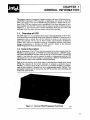
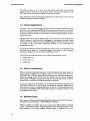
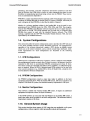
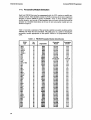
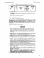
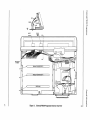
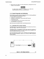
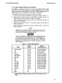
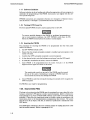
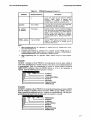
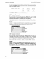
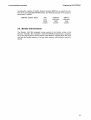

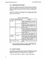
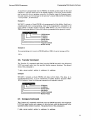
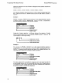
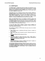

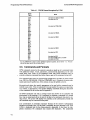
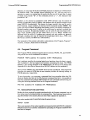
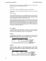
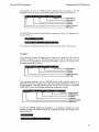
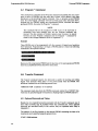
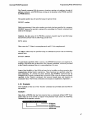
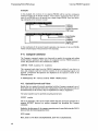
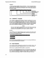
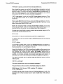
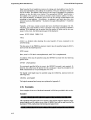

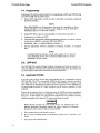
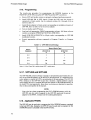
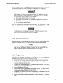
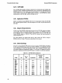
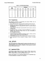
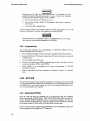
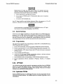
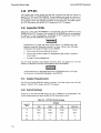

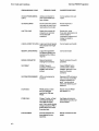
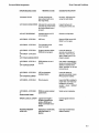
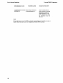
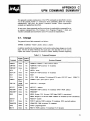
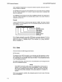
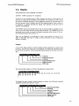
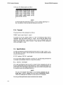
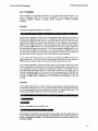
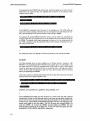
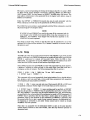
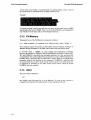


![Umted State Patent [19] [11] 4,142,232](http://vs1.manualzilla.com/store/data/005874596_1-c39d4064b00ab778afe28c128abc9f97-150x150.png)