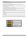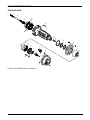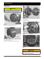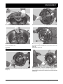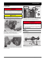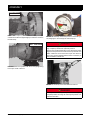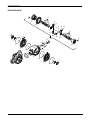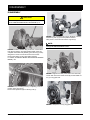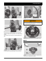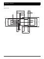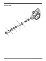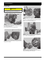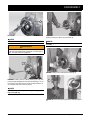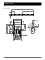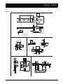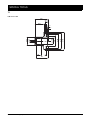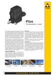
1
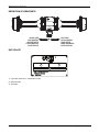
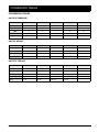
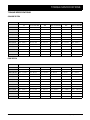
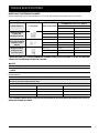
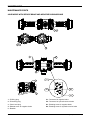
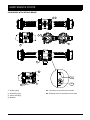
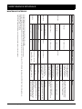
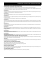
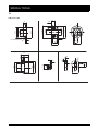
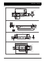
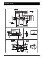
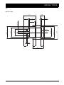
Service Manual
Axle 114
ASM-0006E
July 2015
CONTENTS
INTRODUCTION ................................................................................................................................ 5
SPECIFICATIONS .............................................................................................................................. 7
DEFINITION OF VIEWPOINTS ...................................................................................................................... 7
DATA PLATE ................................................................................................................................................. 7
CONVERSION TABLES ................................................................................................................................ 8
UNITS OF PRESSURE ............................................................................................................................. 8
UNIT OF WEIGHT .................................................................................................................................... 8
UNITS OF TORQUE ................................................................................................................................. 8
TORQUE SPECIFICATIONS ......................................................................................................................... 9
COARSE PITCH ....................................................................................................................................... 9
FINE PITCH .............................................................................................................................................. 9
WHEEL NUT TIGHTENING TORQUES .................................................................................................... 10
MAINTENANCE ................................................................................................................................. 11
MAINTENANCE POINTS .............................................................................................................................. 11
AXLE MODEL WITH SERVICE BRAKE AND NEGATIVE PARKING BRAKE ........................................... 11
AXLE MODEL WITH SERVICE BRAKE .................................................................................................... 12
OIL DRAINING MANDATORY PROCEDURE ................................................................................................ 13
CENTRAL HOUSING ............................................................................................................................... 13
PLANETARY GEAR REDUCTION ............................................................................................................ 13
MAINTENANCE INTERVALS ........................................................................................................................ 14
LUBRICANT & SEALANT SPECIFICATIONS ................................................................................................ 15
SAFETY PRECAUTIONS ................................................................................................................... 17
PLANETARY REDUCTION ................................................................................................................ 19
EXPLODED VIEW .......................................................................................................................................... 19
DISASSEMBLY ............................................................................................................................................. 20
ASSEMBLY ................................................................................................................................................... 24
SPECIAL TOOLS .......................................................................................................................................... 29
T1 ............................................................................................................................................................. 29
T2 ............................................................................................................................................................. 30
T3 ............................................................................................................................................................. 31
T4 ............................................................................................................................................................. 32
SERVICE BRAKE ............................................................................................................................... 33
EXPLODED VIEW .......................................................................................................................................... 33
DISASSEMBLY ............................................................................................................................................. 34
ASSEMBLY ................................................................................................................................................... 36
SERVICE BRAKE AND NEGATIVE PARKING BRAKE .................................................................... 39
EXPLODED VIEW .......................................................................................................................................... 39
RELEASE ...................................................................................................................................................... 40
ADJUSTMENT .............................................................................................................................................. 40
DISASSEMBLY ............................................................................................................................................. 41
ASSEMBLY ................................................................................................................................................... 45
DIFFERENTIAL .................................................................................................................................. 51
EXPLODED VIEW .......................................................................................................................................... 51
DISASSEMBLY ............................................................................................................................................. 52
ASSEMBLY ................................................................................................................................................... 55
SPECIAL TOOLS .......................................................................................................................................... 61
T1 ............................................................................................................................................................. 61
T2 ............................................................................................................................................................. 62
ASM-0006E - 114 Axle Service Manual
Dana Holding Corporation
3
BEVEL PINION ................................................................................................................................... 63
EXPLODED VIEW .......................................................................................................................................... 63
DISASSEMBLY ............................................................................................................................................. 64
ASSEMBLY ................................................................................................................................................... 67
SEAL RING REPLACEMENT ........................................................................................................................ 72
DISASSEMBLY ........................................................................................................................................ 72
ASSEMBLY .............................................................................................................................................. 72
SPECIAL TOOLS .......................................................................................................................................... 73
T1 ............................................................................................................................................................. 73
T2 ............................................................................................................................................................. 74
T3 ............................................................................................................................................................. 76
T4 ............................................................................................................................................................. 77
T5 ............................................................................................................................................................. 78
T6 ............................................................................................................................................................. 79
T7 ............................................................................................................................................................. 80
4
Dana Holding Corporation
ASM-0006E - 114 Axle Service Manual
INTRODUCTION
The efficiency and continued operation of mechanical units depend on constant, correct maintenance and also on efficient repair work, should there be a break-down or malfunction. The instructions contained in this manual have been based on a complete overhaul of the unit. However, it is up to the mechanic to decide whether or not it is necessary to assemble only individual
components, when partial repair work is needed. The manual provides a quick and sure guide which, with the use of photographs and diagrams illustrating the various phases of the operations, allows accurate work to be performed.All the information
needed for correct disassembly, checks and assembly of each individual component is set out below. In order to remove the
differential unit from the vehicle, the manuals provided by the vehicle manufacturer should be consulted. In describing the following operations it is presumed that the unit has already been removed from the vehicle.
IMPORTANT: In order to facilitate work and protect both working surfaces and operators, it is advisable to use proper equipment such as: trestles or supporting benches, plastic or copper hammers, appropriate levers, pullers and specific spanners or
wrenches. Before going on to disassemble the parts and drain the oil, it is best to thoroughly clean the unit, removing any encrusted or accumulated grease.
INTRODUCTORY REMARKS: All the disassembled mechanical units should be thoroughly cleaned with appropriate products
and restored or replaced if damage, wear, cracking or seizing have occurred. In particular, thoroughly check the condition of
all moving parts (bearings, gears, ring gear and pinion, shafts) and sealing parts (o-rings, oil shields) which are subject to major
stress and wear. In any case, it is advisable to replace the seals every time a component is overhauled or repaired. During assembly, the sealing rings must be lubricated on the sealing edge. In the case of the ring gear and pinion, replacement of one
component requires the replacement of the other one. During assembly, the prescribed pre-loading, backlash and torque of
parts must be maintained.
SPECIFIC EQUIPMENT AND SPARE PARTS: The drawings of all specific tools required for maintenance and repair work can
be found at the end of this manual ; spare parts may be ordered either from the vehicle manufacturer or directly from the Service
Centers or Authorized Distributors of Dana Holding.
ASM-0006E - 114 Axle Service Manual
Dana Holding Corporation
5
6
Dana Holding Corporation
ASM-0006E - 114 Axle Service Manual
SPECIFICATIONS
DEFINITION OF VIEWPOINTS
RIGHT SIDE
LATO DESTRO
RECHTE SEITE
LADO DERECHO
COTE DROITE
LEFT SIDE
LATO SINISTRO
LINKE SEITE
LADO IZQUIERDO
COTE GAUCHE
DATA PLATE
R
2
1
3
MFG. BY DANA ITALIA S.P.A.
38062 Arco (Trento)
MADE IN ITALY
1 - Type and model unit - modification index
2 - Serial number
3 - Lubricant
ASM-0006E - 114 Axle Service Manual
Dana Holding Corporation
7
CONVERSION TABLES
CONVERSION TABLES
UNITS OF PRESSURE
Atm
Bar
MPa
Pa
PSI
Atm
1
1
0,1
105
14,4
Bar
1
1
0,1
105
14,4
MPa
10
10
1
106
144
Pa
0,00001
0,00001
10-6
1
-
PSI
-
-
-
-
1
N
daN
kN
kg
lbs
UNIT OF WEIGHT
1N
1
0,1
0,001
0,102
0,225
1daN
10
1
0,01
1,02
2,25
1kN
1000
100
1
102
225
1kg
9,81
0,981
0,00981
1
2,205
UNITS OF TORQUE
N·m
daN·m
kN·m
kg·m
lb·in
1N·m
1
0,1
0,001
0,102
8,854
1daN·m
10
1
0,01
1,02
88,54
1kN·m
1000
100
1
102
8854
1kg·m
9,81
0,981
0,00981
1
86,8
1 lb·in
0,1129
0,01129
0,0001129
0,01152
1
8
Dana Holding Corporation
ASM-0006E - 114 Axle Service Manual
TORQUE SPECIFICATIONS
TORQUE SPECIFICATIONS
COARSE PITCH
SIZE OF BOLT
TYPE OF BOLT
8.8
8.8 + Loctite 270
10.9
10.9 + Loctite 270
12.9
12.9 + Loctite 270
M6 x 1 mm
9,5 – 10,5 N·m
10,5 – 11,5 N·m
14,3 – 15,7 N·m
15,2 – 16,8 N·m
16,2 – 17,8 N·m
18,1 – 20 N·m
M8 x 1,25 mm
23,8 – 26,2 N·m
25,6 – 28,4 N·m
34,2 – 37,8 N·m
36,7 – 40,5 N·m
39 – 43 N·m
43,7 – 48,3 N·m
M10 x 1,5 mm
48 – 53 N·m
52 – 58 N·m
68 – 75 N·m
73 – 81 N·m
80 – 88 N·m
88 – 97 N·m
M12 x 1,75 mm
82 – 91 N·m
90 – 100 N·m
116 – 128 N·m
126 – 139 N·m
139 – 153 N·m
152 – 168 N·m
M14 x 2 mm
129 – 143 N·m
143 – 158 N·m
182 – 202 N·m
200 – 221 N·m
221 – 244 N·m
238 – 263 N·m
M16 x 2 mm
200 – 221 N·m
219 – 242 N·m
283 – 312 N·m
309 – 341 N·m
337 – 373 N·m
371 – 410 N·m
M18 x 2,5 mm
276 – 305 N·m
299 – 331 N·m
390 – 431 N·m
428 – 473 N·m
466 – 515 N·m
509 – 562 N·m
M20 x 2,5 mm
390 – 431 N·m
428 – 473 N·m
553 – 611 N·m
603 – 667 N·m
660 – 730 N·m
722 – 798 N·m
M22 x 2,5 mm
523 – 578 N·m
575 – 635 N·m
746 – 824 N·m
817 – 903 N·m
893 – 987 N·m
974 – 1076 N·m
M24 x 3 mm
675 – 746 N·m
732 – 809 N·m
950 – 1050 N·m
1040 – 1150 N·m
1140 – 1260 N·m
1240 – 1370 N·m
M27 x 3 mm
998 – 1103 N·m
1088 – 1202 N·m
1411 – 1559 N·m
1539 – 1701 N·m
1710 – 1890 N·m
1838 – 2032 N·m
M30 x 3,5 mm
1378 – 1523 N·m
1473 – 1628 N·m
1914 – 2115 N·m
2085 – 2305 N·m
2280 – 2520 N·m
2494 – 2757 N·m
FINE PITCH
SIZE OF BOLT
TYPE OF BOLT
8.8
8.8 + Loctite 270
10.9
10.9 + Loctite 270
12.9
12.9 + Loctite 270
M8 x 1 mm
25,7 – 28,3 N·m
27,5 – 30,5 N·m
36,2 – 39,8 N·m
40 – 44 N·m
42,8 – 47,2 N·m
47,5 – 52,5 N·m
M10 x 1,25 mm
49,4 – 54,6 N·m
55,2 – 61 N·m
71,5 – 78,5 N·m
78 – 86 N·m
86 – 94 N·m
93 – 103 N·m
M12 x 1,25 mm
90 – 100 N·m
98 – 109 N·m
128 – 142 N·m
139 – 154 N·m
152 – 168 N·m
166 – 184 N·m
M12 x 1,5 mm
86 – 95 N·m
94 – 104 N·m
120 – 132 N·m
133 – 147 N·m
143 – 158 N·m
159 – 175 N·m
M14 x 1,5 mm
143 – 158 N·m
157 – 173 N·m
200 – 222 N·m
219 – 242 N·m
238 – 263 N·m
261 – 289 N·m
M16 x 1,5 mm
214 – 236 N·m
233 – 257 N·m
302 – 334 N·m
333 – 368 N·m
361 – 399 N·m
394 – 436 N·m
M18 x 1,5 mm
312 – 345 N·m
342 – 378 N·m
442 – 489 N·m
485 – 536 N·m
527 – 583 N·m
580 – 641 N·m
M20 x 1,5 mm
437 – 483 N·m
475 – 525 N·m
613 – 677 N·m
674 – 745 N·m
736 – 814 N·m
808 – 893 N·m
M22 x 1,5 mm
581 – 642 N·m
637 – 704 N·m
822 – 908 N·m
903 – 998 N·m
998 – 1103 N·m
1078 – 1191 N·m
M24 x 2 mm
741 – 819 N·m
808 – 893 N·m
1045 – 1155 N·m
1140 – 1260 N·m
1235 – 1365 N·m
1363 – 1507 N·m
M27 x 2 mm
1083 – 1197 N·m
1178 – 1302 N·m
1520 – 1680 N·m
1672 – 1848 N·m
1834 – 2027 N·m
2000 – 2210 N·m
M30 x 2 mm
1511 – 1670 N·m
1648 – 1822 N·m
2138 – 2363 N·m
2332 – 2577 N·m
2565 – 2835 N·m
2788 – 3082 N·m
ASM-0006E - 114 Axle Service Manual
Dana Holding Corporation
9
TORQUE SPECIFICATIONS
WHEEL NUT TIGHTENING TORQUES
Wheel nut tightening torques recommended from rim's O.E.M. with reference to the quality of the rim's material.
WHEEL NUT TIGHTENING TORQUES
RECOMMENDED WHEEL NUTS TORQUE
CHARACTERISTICS
ILLUSTRATION
WHEEL STUD THREAD
RIM MATERIAL QUALITY
ST 37
WHEEL NUTS WITH
INTEGRATED
SPHERICAL COLLAR
FLAT COLLAR WHEEL
NUTS WITH SEPARATE
SPHERICAL LOCK
WASHER
WHEEL NUTS WITH
INTEGRATE SEAT
CAPTIVE WASHER
**ST 52
M18X1,5 mm
330 N·m
460 N·m
M20X1,5 mm
490 N·m
630 N·m
M22X1,5 mm
630 N·m
740 N·m
M18X1,5 mm
270 N·m
360 N·m
M20X1,5 mm
360 N·m
450 N·m
M22X1,5 mm
460 N·m
550 N·m
M18X1,5 mm
260 N·m
360 N·m
M20X1,5 mm
350 N·m
500 N·m
M22X1,5 mm
450 N·m
650 N·m
**RIM'S MATERIAL ST 52 IS RECOMMENDED BY DANA ON AXLE APPLICATIONS. IT IS THE OPTIMUM MATERIAL FOR TIGHTENING THE RIM TO THE HUB.
NOTE:
The wheel nut tightening torque is related only on nut thread and stud thread dry. (Without oil or any lubricant).
NOTE:
The wheel nut tightening torque takes into consideration not only the nut + stud characteristics, but also the quality of
the rim material.
THE DANA OFFICIAL TIGHTENING TORQUE TABLE, THAT IS INCLUDED IN EACH SERVICE MANUAL, SHOWS THE TORQUE FIGURE
RELATED TO THE BOLT CHARACTERISTIC ONLY.
DANA OFFICIAL TIGHTENING TORQUE TABLE
NUT MATERIAL QUALITY 8.8 & 10.9
STUD MATERIAL QUALITY 10.9
*ALLOW TIGHT TORQUE
M18 x 1,5 mm
M18 x 1,5 N·m
442 - 489 N·m
M20 x 1,5 mm
M20 x 1,5 N·m
613 - 677 N·m
M22 x 1,5 mm
M22 x 1,5 N·m
822 - 908 N·m
*THE TORQUE FIGURE ON NUT AND STUD COUPLING MUST BE RELATED ON STUD MATERIAL QUALITY
(DANA AXLES ARE 10.9 ONLY).
10
Dana Holding Corporation
ASM-0006E - 114 Axle Service Manual
MAINTENANCE
MAINTENANCE POINTS
AXLE MODEL WITH SERVICE BRAKE AND NEGATIVE PARKING BRAKE
1
1
3
3
2
4
4
5
1
P1
B2
B1
2
3
P2
1 - Oil filling plug
P1 - Connector for negative brake
2 - Oil draining plug
P2 - Connector for hydraulic service brake
3 - Check level plug
B1 - Bleeding screw for negative brake
4 - Release screw for negative brake
B2 - Bleeding screw for hydraulic service brake
5 - Breather
ASM-0006E - 114 Axle Service Manual
Dana Holding Corporation
11
MAINTENANCE POINTS
AXLE MODEL WITH SERVICE BRAKE
1
1
3
3
2
2
4
1
P2
2
3
B2
1 - Oil filling plug
P2 - Connector for hydraulic service brake
2 - Oil draining plug
B2 - Bleeding screw for hydraulic service brake
3 - Check level plug
4 - Breather
12
Dana Holding Corporation
ASM-0006E - 114 Axle Service Manual
OIL DRAINING MANDATORY PROCEDURE
OIL DRAINING MANDATORY PROCEDURE
WARNING
•
•
Do not attempt any maintenance if the axle is hot (40-50°C / 104-122°F). Hot oil and components can cause personal injury. Avoid skin contact. Wear protective gloves and glasses.
Make sure all fluids are contained during inspection, maintenance, tests, adjustment and repair of the product. Prepare a
suitable container to collect the fluid before removing any component containing fluids. Dispose of all fluids following legal
and local regulations.
CENTRAL HOUSING
Before draining oil it is mandatory to loosen the oil filling plug or the breather (if present), and wait until the internal pressure is
completely released. Remove the oil draining plug and drain oil only when the pressure is completely released.
PLANETARY GEAR REDUCTION
Before draining oil it is mandatory to rotate the planetary gear reduction in order to move the oil plug in filling position, then
loosen the oil plug and wait until the internal pressure is completely released. Remove the oil plug and drain oil only when the
pressure is completely released.
ASM-0006E - 114 Axle Service Manual
Dana Holding Corporation
13
MAINTENANCE INTERVALS
MAINTENANCE INTERVALS
Oil level check
OPERATION
All
COMPARTMENT
100 - 250 whs max. *
10 whs
1ST CHANGE /
CHECK (whs)
100 - 250 whs max. *
10 whs
10 whs
Monthly
FREQUENCY (whs)
For details see below
LUBRICANTS
If with limited slip differential, and/or
wet brakes, use LS additivated oils.
Clean carefully oil plug magnet.
Clean carefully oil plug magnet
REMARKS
Central body hypoid bevel
gears - SAE80W/90 (API GL5)
Supply grease until clean grease is visible from outside.
Grease performance level acc. to: According to DIN 51825 level KP2K-30
(NLGI2) or KP3K-20 (NLGI3); ASTM
D4950 NLGI2 GC-LB
Check for any damage or corrosion of
treads or mating surfaces
DOT brake fluids oils are NOT compatible w/std oils
Not applicable
Clean carefully oil plug magnet.
* in accordance with Machine Service
requirements
Clean carefully oil plug magnet.
Central body standard bevel
gears - UTTO (API GL4), or
gear: J20/C, MF M1143, or
gear: SAE80W/90 (API GL4
or GL5)
1000 whs
UTTO (API GL4) J20/C; or
gear: SAE80W/90 (API GL4
or GL5)
Gears with wet discs clutch ATF GM Dexron IIE, Dexron III
Only gears - UTTO J20/C, or
gear: SAE80W/90 (API GL4
or GL5)
100 - 250 whs max. *
Dropbox (if any)
Every 500 whs
Wheel nuts
10 whs
100 whs
Negative brake (SAHR)
For hydraulic actuations
(brakes, SAHR, 100% diff.
lock, etc.) use ATF oil e.g. GM
Dexron IIE, Dexron III
King Pin Tapered Bearings
Service brake
Seals
10 whs
NLGI2 EP or NLGI3 EP with
Moly Addittive
NLGI2 EP or NLGI3 EP
No lubricant allowed
King Pin Bushings
10 whs
Normal work – Weekly
or
Severe duty – Daily
Every 200 whs
Hub Reduction
Differential
Oil Change
Adjustment
Tightening
Greasing
Trunnion Bushings
In case of severe duty, half oil change intervals must be applied.
In case of extreme enviroments, chatter noise, reduce oil change intervals accordingly.
In case of extremely low ambient temperatures (<-20°C), use appropriate oils w/ low viscosity: UTTO J20/D (std Bevel Gears), SAE 75W/90 API GL5 LS (Hypoid Bevel
Gears: models 192, 193, 194).
API GL5: Acc. To MIL L-2105-B
See PSB 00279 (latest update) for more info regarding lubricants and viscosity grades.
ASM-0006E - 114 Axle Service Manual
Dana Holding Corporation
14
LUBRICANT & SEALANT SPECIFICATIONS
LUBRICANT & SEALANT SPECIFICATIONS
1 - Locking, sealing and lubricating materials referred to in this manual are the same used in the shop-floor.
2 - The table below gives an account of the typical applications of each single material, in order to facilitate replacement with
similar products marketed by different brand names with different trade marks.
LOCTITE 242
Anaerobic product apt to prevent the loosening of screws, nuts and plugs. Used for medium-strength locking. Before using it,
completely remove any lubricant by using the specific activator.
LOCTITE 243
The oleocompatible alternative to 242. Does not require the activation of lubricated surfaces.
LOCTITE 270
Anaerobic product for very-high strength locking of screws and nuts. Before using it, completely remove any lubricant by using
the specific activator.
To remove parts, it may be necessary to heat them at 80° C approximately.
LOCTITE 275
Anaerobic product suitable for high-strength locking and sealing of large threaded parts, bolts and stud bolts, for pipe sealing
and for protecting parts against tampering; suitable for sealing coupling surfaces with a maximum diametrical clearance of 0.25
mm.
LOCTITE 510
Anaerobic product for the hermetic sealing of flanged units and screw holes communicating with fluids. Can seal clearances
between flanges up to 0.2 mm.
LOCTITE 577
Quick anaerobic sealant for sealing threaded portions of conical or cylindrical unions up to M80. Before using it, remove any
lubricant with the specific activator. After polymerisation, disassembly may result rather difficult, so heating may be necessary
for larger diameters.
LOCTITE 638
Anaerobic adhesive for fast and high-strength gluing of cylindrical metal joints (hub on shaft). Can glue together parts with clearance ranging between 0.1 and 0.25 mm.
LOCTITE 648
Anaerobic adhesive for fast and medium-strength gluing of cylindrical metal joints (hub on shaft). Can glue together parts with
radial clearance below 0.1 mm.
AREXONS (REPOSITIONABLE JOINTING COMPOUND FOR SEALS)
Solvent-based sealing compound for elastic seals, drying through evaporation. Used for sealing the outer diameter of sealing
rings for rotating shafts with outer metal reinforcement.
SILICONE
Semi-fluid adhesive material used for sealing and filling and to protect components from environmental and physical elements.
Polymerises with non-corrosive dampness.
TECNO LUBE/101 (SILICONE-BASED GREASE)
Highly adhesive synthetic grease, with silicone compounds added.
Applied to adjustment screws with hole communicating with oil-type fluids.
Used when frequent adjusting is required.
MOLIKOTE (DOW CORNING)
Lubricating compound containing molybdenum disulphide, used to lubricate articulation pins and to prevent sticking and oxidation of parts that are not lubricated on a regular basis.
(LITHIUM-BASED) GREASE
Applied to bearings, sliding parts and used to lubricate seals or parts during assembly.
ASM-0006E - 114 Axle Service Manual
Dana Holding Corporation
15
LUBRICANT & SEALANT SPECIFICATIONS
16
Dana Holding Corporation
ASM-0006E - 114 Axle Service Manual
SAFETY PRECAUTIONS
1 - During all operations described in this manual, the axle should be fastened onto a trestle, while the other parts
mentioned should rest on supporting benches.
2 - When removing one of the arms, an anti-tilting safety trestle should be placed under the other arm.
3 - When working on an arm that is fitted on the machine, make sure that the supporting trestles are correctly po-
sitioned and that the machine is locked lengthways.
4 - Do not admit any other person inside the work area; mark off the area, hang warning signs and remove the igni-
tion key from the machine.
5 - Use only clean, quality tools; discard all worn, damaged, lowquality or improvised wrenches and tools. Ensure
that all torque wrenches have been checked and calibrated.
6 - During maintenance operations, always wear protective glasses, safety footwear, protective gloves and all
P.P.E. (Personal Protective Equipment) in function of the risks which the workers may be exposed to.
7 - Should you stain a surface with oil, remove marks straight away.
8 - Dispose of all lubricants, seals, rags and solvents once work has been completed. Treat them as special waste
and dispose of them according to the relative law provisions obtaining in the country where the axles are being
overhauled.
9 - Make sure that only weak solvents are used for cleaning purposes; avoid using turpentine, dilutants and toluol,
xylolbased or similar solvents; use light solvents such as Kerosene, mineral spirits or water-based, environment
friendly solvents.
10 - For the sake of clarity, the parts that do not normally need to be removed have not been reproduced in some
of the diagrams.
11 - After repair work has been completed, accurately touch up any coated part that may have been damaged.
12 - Follow all safety instructions in the Original Equipment Manufacturer (OEM) manual that came with the vehicle.
13 - Before draining oil, release the internal pressure, for details see OIL DRAINING MANDATORY PROCEDURE
p. 13.
DANGER
Indicates an imminently hazardous situation
which, if not avoided, will result in death or serious injury.
WARNING
Indicates an imminently hazardous situation
which, if not avoided, could result in death or serious injury.
CAUTION
Indicates a situation which, if not avoided, may
result in damage to components.
NOTICE
Indicates information which may make product
service easier to perform.
ASM-0006E - 114 Axle Service Manual
Dana Holding Corporation
17
LUBRICANT & SEALANT SPECIFICATIONS
18
Dana Holding Corporation
ASM-0006E - 114 Axle Service Manual
PLANETARY REDUCTION
EXPLODED VIEW
19
24
26
23
22
25
20
21
5
18
13
17
12
16
11
4
9
15
5
14
27
6
21
3
10
7
2
1
ITEM 27 NOT PRESENT ON ALL MODELS
ASM-0006E - 114 Axle Service Manual
Dana Holding Corporation
19
DISASSEMBLY
DISASSEMBLY
CAUTION
Before draining oil, release the internal pressure, for details
see OIL DRAINING MANDATORY PROCEDURE p. 13.
3
FIGURE 3: Using two screwdrivers or two levers inserted in
the slots provided, disjoin the planetary cover (3) away from
the wheel hub (16).
Remove the cover (3).
1
FIGURE 1: Carry out all operations one wheel side at a time.
Remove the oil level plug (1) and drain the oil.
3
6
FIGURE 4: Remove the sun gear (6).
2
FIGURE 2: Attach a suitable sling to the satellite carrier cover,
connect to lifting gear, and tighten. The approximate weight
of the cover is 67kg (148lb).
Remove the locking screws (2) of planetary cover (3).
4
5
FIGURE 5: Remove the snap rings (4) of the planetary gears
(5).
WARNING
Removal of the snap rings can cause personal injuries. You
must wear appropriate safety equipment. To avoid injury to
eyes, wear eye protection equipment.
20
Dana Holding Corporation
ASM-0006E - 114 Axle Service Manual
DISASSEMBLY
9
5
FIGURE 6: Remove the planetary gears (5).
FIGURE 9: Remove the safety flange (9).
16
27
11
FIGURE 7: NOT PRESENT ON ALL MODELS
Remove the spacer (27).
FIGURE 10: Using two screwdrivers or two levers inserted in
the slots provided, disengage the crown wheel (11) from the
hub (16).
Remove the crown (11).
NOTE:
Write down the direction of assembly of the spacer.
7
16
FIGURE 8: Loosen and remove the nuts (7) from the crown
flange (11).
ASM-0006E - 114 Axle Service Manual
FIGURE 11: Tighten fully into the hole provided a double joint
lifting eye size M12, connect to a suitable lifting gear and tension. The approximate weight of the hub is 42kg (92,5lb).
With the help of a hammer, shift the hub (16) and the external
bearing (14).
Dana Holding Corporation
21
DISASSEMBLY
17
14
14
16
FIGURE 12: Extract the external bearing (14).
FIGURE 15: Remove the external thrust blocks of bearings
(14) and (17), using a pin driver.
NOTE:
Hammer in an alternate sequence to prevent clamping
and deformation of the thrust blocks.
18
30-35 Bar
P1
16
B1
FIGURE 13: Remove the seal ring (18) from the hub (16).
B2
P2
NOTE:
Write down direction of assembly.
CAUTION
The seal ring may not be reused.
FIGURE 16: ONLY NEGATIVE BRAKE VERSION
Connect an external pump to the union piece “P1“ of the negative brake and introduce a pressure of 30 - 35 bar to eliminate the pressure of the Belleville washers.
WARNING
18
Hot oil and components can cause personal injury. Avoid
skin contact.
NOTE:
Perform all operations on both arms. Remove the oil plug
"A" and drain oil.
FIGURE 14: Remove the internal bearing (18).
22
Dana Holding Corporation
ASM-0006E - 114 Axle Service Manual
DISASSEMBLY
26
B
FIGURE 17: If axle is positioned on an overhaul bench, place
a safety anti-tilting stand “B” under the arm that remains connected and block wheels, if any.
FIGURE 20: Remove the flange (26) complete with the discs.
Noting down direction of assembly.
For details, see SERVICE BRAKE AND NEGATIVE PARKING
BRAKE p. 39.
19
FIGURE 18: Connect a suitable sling to the arm, connect to
lifting gear and tighten. The approximate weight of the arm
complete with brakes and planetary gears is 351kg (774lb).
A
FIGURE 21: Remove the axle shaft (19).
1
4
21
20
3
FIGURE 19: Loosen and remove the screws (4) that attach
the arm (3) to the central body (6). Remove arm together with
brakes and axle shafts; lay down the arm vertically.
FIGURE 22: Turn the arm over using the lifting gear. The arm
was attached to the sling during dismantling. The approximate weight of the arm complete with brakes and planetary gears is 351kg (774lb).
Using an extractor, remove seal ring (21) and guide ring (20).
NOTE:
Write down the direction of assembly of seal ring.
ASM-0006E - 114 Axle Service Manual
Dana Holding Corporation
23
ASSEMBLY
ASSEMBLY
Lubricate
20
T1
17
T3
14
FIGURE 23: Lubricate and fit the guide ring (20) onto tool T3
(See drawing T3 p. 31); install the rings into the arm.
FIGURE 25: Position the wheel hub (16) under a press.
Lubricate the seat of the bearing cones (14, 17) and, using
tool T1 (See drawing T1 p. 29), install the bearing cup of the
bearing cone (14, 17).
CAUTION
Pay particular attention to the direction of assembly of the
rings.
17
21
T4
FIGURE 24: Lubricate and fit the seal ring (21) onto tool T4
(See drawing T4 p. 32); install the rings into the arm.
FIGURE 26: Fit the bearing (17) and seal ring (18) into the internal thrust block.
18
CAUTION
Pay particular attention to the direction of assembly of the
rings.
16
FIGURE 27: Apply a joining compound for seals to the outer
surface of the sealing ring (18).
Position the sealing ring (18) in the hub (16).
NOTE:
Verify the ring (18) is correctly oriented.
24
Dana Holding Corporation
ASM-0006E - 114 Axle Service Manual
ASSEMBLY
14
T2
FIGURE 28: Position tool T2 (See drawing T2 p. 30) and press
the sealing ring (18) into its seat.
FIGURE 30: Install the external bearing cone (14).
NOTE:
CAUTION
Using a plastic hammer, drive the bearing cone to the limit stop by lightly hammering around the edge.
Check the flatness of seal ring.
11
16
FIGURE 31: Fit the complete crown flange (11).
FIGURE 29: Insert and tighten two doublejoint lifting eyes
size M12. Connect to suitable lifting gear and tighten. The approximate weight of the hub is 42 kg (92.5 lb). Install the wheel hub (16).
NOTE:
In order to fasten the flange (11), use a plastic hammer
and alternately hammer on several equidistant points.
NOTE:
Move the bearing cone to the limit stop by hammering
lightly all around the edge.
If assembly is difficult, use a driver with a suitable diameter to seat it.
9
FIGURE 32: Install the security flange (9).
ASM-0006E - 114 Axle Service Manual
Dana Holding Corporation
25
ASSEMBLY
5
7
FIGURE 33: Tighten nuts (7) in two stages, using the crisscross method.
Standard nuts: 214 -236 N·m + Loctite 243
Flanged nuts: 270 - 300 N·m + Driloc
NOTE:
Check the continuous rolling torque on the hub. Torque
15 - 64 Nm.
3
FIGURE 36: Insert the planetary gears (5) into the cover (3).
Lock gears (5) into position by installing the snap rings.
WARNING
Personal injury can result when installing snap ring. The appropriate safety equipment must be worn. To avoid injury to
your eyes, wear protective glasses during this procedure.
6
O-ring
15
FIGURE 34: Install a new o-ring (15) on the centering diameter of wheel hub. Lubricate the o-ring before fitting.
FIGURE 37: Install the solar gear (6).
3
16
27
FIGURE 35: NOT PRESENT ON ALL MODELS
Grease the spacer (27) assemble on the satellite gear (5) as
shown in the figure. Accurately check the orientation.
FIGURE 38: Fit the planetary carrier cover (3) onto the hub (16).
CAUTION
Check that the o-ring is in good condition and in position.
26
Dana Holding Corporation
ASM-0006E - 114 Axle Service Manual
ASSEMBLY
40 - 50 N·m
3
2
grease
FIGURE 39: Lock the planetary carrier cover (3) by tightening
the screws (2). Torque wrench setting for screws: 40 - 50 N·m.
19
A
FIGURE 42: Insert the end plate. Before installing the last brake disc and the end plate, spread grease over the contact
surfaces to hold them in position while mounting on the central housing.
27
“A”
FIGURE 40: Grease sealing face “A” of axle-shaft (19). Install
the axle shaft (19) making sure it is properly engaged in the
sun gear (6).
FIGURE 43: Install the end plate (27) with the oil passage
notch “A” facing downwards.
NOTE:
Be very careful not to damage the seal ring (21).
O-ring
Differential side
B
26
FIGURE 41: 1 - Insert the brake discs (24, 25) in the right sequence, orient them so that the oil circulation holes and the
marks "B" are perfectly lined up.
2 - Install the flange (26) on the arm.
FIGURE 44: Check the condition and position of the cover's
o-ring.
NOTE:
The first brake disc (3) to be inserted must be of steel material.
ASM-0006E - 114 Axle Service Manual
Dana Holding Corporation
27
ASSEMBLY
Loctite 243
550 - 600 N·m
FIGURE 45: The arm was attached to a sling during dismantling.
The approximate weight of the arm complete with brakes and
planetary reduction gear is 351kg (774lb).
Install the complete arm.
Apply Loctite 243 to the threads of the screws (3) and tighten
to a torque of 550 - 600 N·m.
35 - 50 N·m
FIGURE 46: Install the oil-level plug (1).
Torque wrench setting for screws: 30 - 50 N·m
28
Dana Holding Corporation
ASM-0006E - 114 Axle Service Manual
SPECIAL TOOLS
SPECIAL TOOLS
T1
P/N: 910.04.4591
ø55
5x45°
ø194
ø50H7
32
33
21
ø40
ø194
ø188
ø185
ø160
ø65
ø50H7
ø50n6
R
52
ø35
-0.1
-0.15
15
ø90H8
ø150
37
120
21
R5
50
M10
1
R2
R5
ø15
R5
20
15
35
20
17°
46,5
60
°
60
°
60
5x15°
ø185
ø188
140
182
2
17°
ø50
30
ASM-0006E - 114 Axle Service Manual
Dana Holding Corporation
29
SPECIAL TOOLS
T2
P/N: 910.06.4592
ø208
ø70
-0.08
-0.12
ø40
ø18
29
50
90°
10
ø20
230
ø8,5
4,5
1 25
10
4
1
20
M8
M10
ø30
45
25
ø70H7
ø145H7
ø158,2
ø164,5h8
ø194
47
42
10
ø30
11,5
ø24H11
ø18H11
-0.2
+0.
+0.3
-0.
27 17
21
ø8
51,5 20
29
ø8
16
26 24
-0.3
+0.
50
ø25
160
140
ø145g6
ø70g6
ø32
45
50
ø11
87
67
-0.3
+0.
56
25
ø18
ø24
30
Dana Holding Corporation
ASM-0006E - 114 Axle Service Manual
SPECIAL TOOLS
T3
P/N: 910.06.4594
ø55p6
ø70
ø40
3x15°
3x15°
223
ø70
3x15°
ø55H7
13
28
ø42
126
15°
105
151
85
10
89
20
ø56
-0.1
-0.2.
ø51
ø57
ø67
ø71
ASM-0006E - 114 Axle Service Manual
-0.3
-0.4
Dana Holding Corporation
31
SPECIAL TOOLS
T4
P/N: 910.04.4595
ø84
ø55p6
ø70
ø40
85
3x45°
89
20
10
3x15°
ø56
ø40
ø55H7
-0.2
+0.
5x15°
3
110
94
112
89
-0.2
+0.
151
0.8
15°
ø49,5
ø70
ø69,5
-0.3
ø71 -0.4
32
Dana Holding Corporation
ASM-0006E - 114 Axle Service Manual
SERVICE BRAKE
EXPLODED VIEW
1
14
3
4
7
8
9
10
11
2
5
6
12
13
ASM-0006E - 114 Axle Service Manual
Dana Holding Corporation
33
DISASSEMBLY
DISASSEMBLY
DANGER
Before maintaining brakes, when the axle is installed on the
vehicle, follow all safety instructions in the Original Equipment Manufacturer (OEM) manual that came with the vehicle.
CAUTION
Before draining oil, release the internal pressure, for details
see OIL DRAINING MANDATORY PROCEDURE p. 13.
NOTE:
Perform all operations on both arms. Remove the oil plug
"A" and drain oil.
FIGURE 3: Remove arm together with brakes and axle shafts;
set the arm in a vertical position using suitable brackets to
keep it locked in place.
Release pressure.
B
1
A
FIGURE 1: If axle is positioned on an overhaul bench, place
a safety anti-tilting stand “B” under the arm that remains connected and block wheels, if any.
FIGURE 4: Write down the order of assembly and remove the
end plate (1).
2
FIGURE 2: Attach a suitable sling to the arm, connect to lifting gear and tighten. The approximate weight of the arm
complete with brakes and planetary gears is 351 kg (774 lb).
Remove the retainer screws.
34
Dana Holding Corporation
FIGURE 5: Remove braking discs (2, 3), noting down direction of assembly.
NOTE:
If disks are not to be replaced, avoid changing their position.
ASM-0006E - 114 Axle Service Manual
DISASSEMBLY
4
5
FIGURE 6: Remove the flange (4) complete with the discs.
Noting down direction of assembly.
FIGURE 9: Remove the adjusting screws (5).
14
9
FIGURE 10: Slowly introduce low-pressure compressed air
through the connection member for the service brake, in order to extract the piston (9).
FIGURE 7: Remove the axle shaft.
NOTE:
Be very careful not to damage the seal ring.
CAUTION
Hold the piston (9) back, as it may be suddenly ejected and
damaged.
7
8
FIGURE 8: Remove the reversal springs (8) and screws (7).
NOTE:
If the springs (8) are weak or deformed they must be replaced.
ASM-0006E - 114 Axle Service Manual
Dana Holding Corporation
35
ASSEMBLY
ASSEMBLY
9
9
FIGURE 13: Using a plastic hammer, install the piston (9) into
the arm.
FIGURE 11: Insert the stroke automatic regulation springs (6);
place them in line with the piston (9).
NOTE:
Lightly hammer all around the edge in an alternate sequence.
5 - 7 N·m
Driloc
5
FIGURE 12: Fit o-ring (11, 12) and back-up ring (10, 13) onto
the piston (11).
Lubricate the piston and the o-rings and install the unit into
the arm.
O-ring
FIGURE 14: Fit the adjusting screws (5).
Torque wrench setting: 5 -7 N·m.
CAUTION
Use only new screws pre-treated with Driloc locking adhesive. Threads must be cleaned from oil.
Degrease only non pre-treated threads.
Back up ring
36
Dana Holding Corporation
ASM-0006E - 114 Axle Service Manual
ASSEMBLY
first disc
7
15 - 20 N·m
Driloc
3
8
FIGURE 15: Fit the reversal springs (8) on the piston (9).
Tighten with torque wrench setting of 15 - 20 N·m
FIGURE 17: Insert the brake discs in the right sequence.
NOTE:
The first brake disc (3) to be inserted must be of steel material.
CAUTION
Use only new screws pre-treated with Driloc locking adhesive. Threads must be cleaned from oil.
Degrease only non pre-treated threads.
second disc
2
A
FIGURE 18: The second brake disc (2) to be inserted must be
of friction material.
FIGURE 16: Grease sealing face “A” of axle shaft .
NOTE:
Differential side
Be very careful not to damage the snap ring .
13
FIGURE 19: Install the flange (4) on the arm.
ASM-0006E - 114 Axle Service Manual
Dana Holding Corporation
37
ASSEMBLY
grease
FIGURE 20: Insert the end plate (1). Before installing the last
brake disc and the end plate (1), spread grease over the contact surfaces to hold them in position while mounting on the
central housing.
1
FIGURE 23: The arm was attached to a sling during dismantling.
The approximate weight of the arm complete with brakes and
planetary reduction gear is 351 kg (774 lb).
Check condition and position of the arm's o-ring; install the
complete arm.
NOTE:
To assist axle shaft centering, slightly move the wheel
hub.
Loctite 243
“A”
FIGURE 21: Install the end plate (1) with the oil passage notch
“A” facing downwards.
O-ring
FIGURE 24: Temporarily lock the arm with nuts previously
coated with Loctite 243; tighten lightly to make the unit touch
the main body.
550 - 600 N·m
FIGURE 22: Install the new o-ring. Lubricate before installing.
FIGURE 25: Secure in position with the screws (3) tightening
to a torque of 550 - 600 N·m.
38
Dana Holding Corporation
ASM-0006E - 114 Axle Service Manual
SERVICE BRAKE AND NEGATIVE PARKING BRAKE
EXPLODED VIEW
6
3
4
7
8
1
4
2
29
29
28
18
30
16
9
10
27
17
26
25
30
15
14
11
12
19
13
20
21
22
23
ASM-0006E - 114 Axle Service Manual
Dana Holding Corporation
39
RELEASE
RELEASE
ADJUSTMENT
Tecno Lube 101
23
21
22
23
FIGURE 1: Loosen nuts (22) of screws (23) provided for the
mechanical and manual release of the braking units, then
move the nuts backwards by approximately 8 mm.
FIGURE 4: Remove screws complete with nuts and seals.
Replace seals, apply silicone-based Tecno Lube /101 grease
to the screws and install all parts into the arm.
34 mm
23
FIGURE 2: Tighten screws (23) to fasten the pressure plate
(16).
FIGURE 3: Using a wrench, tighten the screws (23) in an alternate sequence by 1/4 turn at a time so as to compress the
Belleville washers (1) and disengage the braking disks.
FIGURE 5: Adjust screws (23) to obtain a distance of 34 mm
in relation to the arm.
FIGURE 6: Lock into position with nuts (22).
CAUTION
CAUTION
Tighten maximum by one turn.
40
Dana Holding Corporation
Hold screws (23) into position while locking the nuts (22); after locking, check the distance of screws (23) once more.
ASM-0006E - 114 Axle Service Manual
DISASSEMBLY
DISASSEMBLY
30-35 Bar
DANGER
P1
Before maintaining brakes, when the axle is installed on the
vehicle, follow all safety instructions in the Original Equipment Manufacturer (OEM) manual that came with the vehicle.
P1
B2
B1
P2
CAUTION
Before draining oil, release the internal pressure, for details
see OIL DRAINING MANDATORY PROCEDURE p. 13.
FIGURE 9: Connect an external pump to the union piece “P1“
of the negative brake and introduce a pressure of 30 - 35 bar
to eliminate the pressure of the Belleville washers (1).
M16
DANGER
Always check that the hydraulic circuit test for leaks under
pressure. Always use a cardboard or a panel to control the
loss.
A leak from a hole of the size of a pin can cause serious injury. If fluid is injected into the skin it is necessary to seek
immediate medical care.
NOTE:
FIGURE 7: Insert and tighten two double joint lifting eyes size
M16. Connect to suitable lifting gear and tighten. The approximate weight of the unit is 150 kg (331 lb).
Remove fastening screws from the reduction unit.
Perform all operations on both arms. Remove the oil plug
"A" and drain oil.
B
A
FIGURE 8: Disjoin the entire reduction unit from the axle and
place it on a bench.
ASM-0006E - 114 Axle Service Manual
FIGURE 10: If axle is positioned on an overhaul bench, place
a safety anti-tilting stand “B” under the arm that remains connected and block wheels, if any.
Dana Holding Corporation
41
DISASSEMBLY
0 bar
FIGURE 11: Attach a suitable sling to the arm, connect to lifting gear and tighten. The approximate weight of the arm
complete with brakes and planetary gears is 351 kg (774 lb).
FIGURE 14: Gradually release the pressure in the braking circuit, bringing it to zero through the external pump.
DANGER
Do not remove any part of the hydraulic circuit without having completely released the hydraulic pressure.
The removal of pressurized parts or loss caused from releasing these components can cause serious injuries and even
death. A leak from a hole of the size of a pin can cause serious injury. If fluid is injected into the skin it is necessary to
seek immediate medical care.
FIGURE 12: Remove the retainer screws.
FIGURE 15: Gradually loosen the sleeve and remove.
DANGER
FIGURE 13: Remove arm together with brakes and axle
shafts. Set the arm in a vertical position using suitable brackets to keep it locked in a safe condition.
42
Dana Holding Corporation
Carefully check that the hydraulic pressure is discharged
completely before removing the external pump sleeve connected to the brake.
ASM-0006E - 114 Axle Service Manual
DISASSEMBLY
11
16
14
FIGURE 16: Remove braking discs (11, 12), noting direction
of assembly.
FIGURE 19: Remove the adjusting screws (14) from the
counterwasher (16).
NOTE:
If disks are not to be replaced, avoid changing their position.
10
9
13
FIGURE 20: Remove the reversal springs (9) and screws (10).
NOTE:
FIGURE 17: Remove the flange (13) complete with the discs,
noting direction of assembly.
If the springs (9) are weak or deformed they must be replaced.
19
20
16
FIGURE 18: Remove spacer braking discs (19) and shims
(20), noting direction of assembly.
ASM-0006E - 114 Axle Service Manual
FIGURE 21: Write down the order of assembly and remove
the counterwasher (16).
Dana Holding Corporation
43
DISASSEMBLY
M20
25
FIGURE 22: Tighten two safety M20 studs in the main body.
Loosen the capscrews (29) using the criss-cross method and
remove them.
FIGURE 25: Slowly introduce low-pressure compressed air
through the connection member for the service brake (P2), in
order to extract the piston (25).
CAUTION
Hold the piston (25) back, as it may be suddenly ejected and
damaged.
1
17
FIGURE 23: Move the cover (17) outwards while supporting
the Belleville washers (1). Remove the Belleville washers (1)
and write down direction of assembly.
3
FIGURE 26: Slowly introduce low-pressure compressed air
through the connection member for the negative brake (P1),
in order to extract the piston (3).
CAUTION
17
Hold the piston (3) back, as it may be suddenly ejected and
damaged. Write down the order of assembly.
FIGURE 24: Attach a suitable sling to the brake cover, connect to lifting gear, and tighten. The approximate weight of
the brake cover is 45kg (99lb). Remove the studs.
Remove the brake cover (17).
44
Dana Holding Corporation
ASM-0006E - 114 Axle Service Manual
ASSEMBLY
ASSEMBLY
O-ring
3
4
18
Back up ring
17
O-ring
2
FIGURE 29: Using a plastic hammer, install the piston (3) into
the cylinder (17).
NOTE:
Lightly hammer all around the edge in an alternate sequence.
27
FIGURE 27: Fit o-ring (2) and (4) and anti-extrusion ring (18)
onto the piston (3).
25
FIGURE 30: Fit o-ring (27) and anti-extrusion ring (26) onto
the piston (25).
17
26
O-ring
Back up ring
FIGURE 28: Check the position of the anti-extrusion (18) and
o-rings (2) and (4).
Lubricate the piston and the o-rings and install the unit (3) into
the cylinder (17) .
FIGURE 31: The o-rings always have to be assembled from
the pressure facing side.
ASM-0006E - 114 Axle Service Manual
Dana Holding Corporation
45
ASSEMBLY
25
17
FIGURE 32: Lubricate the piston and the o-rings and install
the unit (25) into the cover (17) .
FIGURE 35: Install the new o-ring.
Grease before installing.
25
17
Grease
1
FIGURE 33: Using a plastic hammer, install the piston (25)
into the cover (17).
FIGURE 36: Position the Belleville washers (1) and engage
the cylinder. Spread grease over the contact surfaces to hold
them in position.
NOTE:
Lightly hammer all around the edge in an alternate sequence
NOTE:
Check the direction of Belleville washers (1) and relative
centering.
5
M20
17
FIGURE 34: Assemble the bleed valve (5) and the new o-ring.
Grease before installing.
46
Dana Holding Corporation
FIGURE 37: Connect a suitable sling to the satellite carrier
cover, connect to lifting gear and tighten. The approximate
weight of the cover is 67kg (148lb).
Tighten two safety M20 studs in the main body.
Engage the cover (17).
ASM-0006E - 114 Axle Service Manual
ASSEMBLY
129 - 143 N·m
Loctite 243
P1
17
B2
B1
P2
30 - 35 Bar
FIGURE 38: Insert the screws (29) and tighten them alternately. Tightening the screws (29) to a torque of 129 - 143 N·m.
Remove the studs.
FIGURE 41: Connect an external pump to the negative brake
(P1) and introduce pressure to 30 -35 bar.
DANGER
15
Always check that the hydraulic circuit test for leaks under
pressure. Always use a cardboard or a panel to control the
loss.
A leak from a hole of the size of a pin can cause serious injury. If fluid is injected into the skin it is necessary to seek
immediate medical care.
19
9 10
FIGURE 39: Insert the stroke automatic regulation springs
(15); place them in line with the intermediate disc (19).
15 - 20 N·m
Driloc
FIGURE 42: Fit the reversal springs (9) and screws (10) on the
intermediate disk (16).
Tighten with torque wrench setting of 15 -20 N·m
CAUTION
FIGURE 40: Insert the intermediate disc (19).
ASM-0006E - 114 Axle Service Manual
Use only new screws pre-treated with Driloc locking adhesive. Threads must be cleaned from oil.
Degrease only non pre-treated threads.
Dana Holding Corporation
47
ASSEMBLY
5 - 7 N·m
Driloc
14
FIGURE 43: Install the adjusting screws (14) on the threads
and tighten to 5-7 N·m.
Arm fix x
measurement
= 90.5 ± 0.05 mm
quote = 90,5
FIGURE 46: Arm fix measurement = 90.5 - 0.05 mm
Y = brake gap
CAUTION
Use only new screws pre-treated with Driloc locking adhesive. Threads must be cleaned from oil.
Degrease only non pre-treated threads.
S 20
X
S = 90,5 mm - (x + y + v)
FIGURE 47: Y = 1.5 mm = brake gap
S = 90.5 mm - ( x + y + v ) = Thickness of shims to insert under
the shim washer.
Tolerance = - 0.1 mm
EXAMPLE: 90.5 mm - (30.2 + 57.5 + 1.50) = S = 1.30 mm
FIGURE 44: Take the measurement “X” from the surface of
the intermediate disk to the cover sealing surface with 30 - 35
bar of pressure introduced.
EXAMPLE: X = 30.2 mm
V
1000Kg
S 20
20
FIGURE 48: Grease the shims S (20) and assemble in position on the spacer braking disc (19), then insert them in the
arm.
NOTE:
Make sure the shims are inserted correctly.
FIGURE 45: Put the brake disc pack including the shim under
a press, load with 1000 kg and take the measure “V”.
EXAMPLE: V = 57.5 mm
48
Dana Holding Corporation
ASM-0006E - 114 Axle Service Manual
ASSEMBLY
11
19
12
“A”
FIGURE 49: Install the spacer braking disc (19) with the oil
passage notch “A” facing downwards.
FIGURE 52: Insert the brake discs (11) and (12) in the right sequence. Spread grease over the contact surfaces to hold
them in position while mounting on the central housing.
NOTE:
B
11
The last brake disc to be inserted must be of steel material.
FIGURE 50: Slightly lubricate the braking disks (11, 12) and
fit them in the arm following the correct sequence. Orient
them so the oil circulation holes and the marks “B” are perfectly lined up.
Differential side
FIGURE 53: The arm was attached to a sling during dismantling.
The approximate weight of the arm complete with brakes and
planetary reduction gear is 351 kg (774 lb).
Check condition and position of the arm's o-ring;
Install the complete arm.
NOTE:
To assist axle shaft centering, slightly move the wheel hub.
13
FIGURE 51: Install the flange (13) on the arm.
ASM-0006E - 114 Axle Service Manual
Dana Holding Corporation
49
ASSEMBLY
Loctite 243
0 bar
FIGURE 54: Temporarily lock the arm with nuts previously
coated with Loctite 243; tighten lightly to make the unit touch
the main body.
550 - 600 N·m
FIGURE 56: Gradually release the pressure in the braking circuit, bringing it to zero through the external pump.
DANGER
Do not remove any part of the hydraulic circuit without having completely released the hydraulic pressure.
The removal of pressurized parts or loss caused from releasing these components can cause serious injuries and even
death. A leak from a hole of the size of a pin can cause serious injury. If fluid is injected into the skin it is necessary to
seek immediate medical care.
FIGURE 55: Secure in position with the screws (3) tightening
to a torque of 550 - 600 N·m.
FIGURE 57: Gradually loosen the sleeve and remove.
DANGER
Carefully check that the hydraulic pressure is discharged
completely before removing the external pump sleeve connected to the brake.
50
Dana Holding Corporation
ASM-0006E - 114 Axle Service Manual
DIFFERENTIAL
EXPLODED VIEW
29
16
17
23
26
18
26
24
23
20
29
26
6
1
23
26
15
3
13 28
14
4
4
20
27
12
5
26
7
10
5
8
11
4
5
3 1
7
5
ASM-0006E - 114 Axle Service Manual
4
Dana Holding Corporation
51
DISASSEMBLY
DISASSEMBLY
CAUTION
T1
Before draining oil, release the internal pressure, for details
see OIL DRAINING MANDATORY PROCEDURE p. 13.
FIGURE 3: Only if needing removing or adjusting, uniformly
heat the ring nuts (1) up to a temperature of 80° C.
Using tool T1, loosen and remove the ring nuts (3).
NOTE:
Accurately remove any trace of sealant from the threads
of ring nuts and intermediate covers.
FIGURE 1: Attach a suitable sling to the arm, connect to lifting gear and tension. The approximate weight of the arm
complete with brakes and planetary gears is 351 kg (774 lb).
Sling the arm to be removed and connect it to a hoist.
Remove the retainer screws and relative washers.
For details, see SERVICE BRAKE AND NEGATIVE PARKING
BRAKE p. 39.
1
6
FIGURE 4: Tighten two safety M20 studs in the main body.
Loosen and remove the check screws (6) of intermediate cover (7) on ring gear side.
FIGURE 2: Only if needing removing or adjusting, mark the
position of the ring nuts (1).
Remove the capscrews (3) from the ring nuts (1).
7
FIGURE 5: Disjoin the cover (7) ring gear side.
52
Dana Holding Corporation
ASM-0006E - 114 Axle Service Manual
DISASSEMBLY
13
14
FIGURE 6: Remove the cover and studs.
FIGURE 9: Remove the snap ring (13) and the cap (14).
WARNING
28
Removal of the snap rings can cause personal injuries. You
must wear appropriate safety equipment. To avoid injury to
eyes, wear eye protection equipment.
4
FIGURE 7: Insert an adequately keyed bar in the differential.
Connect the bar to suitable lifting gear. The approximate
weight of the differential complete with crown wheel is 60 kg
(132 lb).
With the help of a bar extract the complete differential unit
(28).
9
O-ring
7
FIGURE 10: If the bearings need replacing, extract the external thrust blocks of the bearings (4) from middle cover (7).
NOTE:
Inspect the o-ring (9).
6
4
FIGURE 8: Tighten two safety M20 studs in the main body.
Loosen and remove the intermediate cover (4) screws (6).
4
28
FIGURE 11: If the bearing needs replacing, extract the bearings (4) from the differential carrier (28).
ASM-0006E - 114 Axle Service Manual
Dana Holding Corporation
53
DISASSEMBLY
25
16
18
FIGURE 12: Remove the ring gear (18) capscrews (16).
FIGURE 15: Remove the planetary gear (25).
27
23
26
FIGURE 13: Remove the screws (27) joining the differential
unit half box.
FIGURE 16: Remove shafts (24), complete with planetary gears (26) and spherical shoulder washers (23).
NOTE:
Mark the coupling marks.
29
25
19
26
25
FIGURE 17: Extract from the differential unit (17) the 2nd planetary gear (25).
Remove the 2nd clutch pack (29) and shim set (19).
FIGURE 14: Remove the upper half box (26) and remove the
clutch pack (29).
CAUTION
CAUTION
If the clutch pack does not need replacing, avoid swapping
discs position.
If the clutch pack does not need replacing, avoid swapping
discs position.
54
Dana Holding Corporation
ASM-0006E - 114 Axle Service Manual
ASSEMBLY
ASSEMBLY
27
29
25
Driloc
FIGURE 21: Assemble the half box with screws (27).
FIGURE 18: Insert the planetary gear (25) and the whole friction unit (29).
23
CAUTION
The match marks on the two half-boxes must correspond.
Use only new screws pre-treated with Driloc locking adhesive. Threads must be cleaned from oil.
Degrease only non pre-treated threads.
71.5 - 78.5 N·m
26
FIGURE 19: Install the planetary gears (26) and spherical
shoulder washers (25) onto the bolts (24). Install the planetary
gear set.
19
FIGURE 22: Fit the complete differential unit in a vice and
tighten the screws (27) holding the two half boxes together to
a torque of 71.5 - 78.5 N·m.
CAUTION
25
25
Tighten screws using the criss-cross method.
FIGURE 20: Insert the planetary gear (25) and the whole friction unit (29).
ASM-0006E - 114 Axle Service Manual
Dana Holding Corporation
55
ASSEMBLY
16
18
Driloc
FIGURE 23: Mount the ring gear (18) and fasten it to the differential with screws (16).
FIGURE 25: Position the differential unit under a press and,
using a driver with an adequate diameter, install the first bearing (4).
Turn the unit upside down and install the second bearing (4).
CAUTION
Use only new screws pre-treated with Driloc locking adhesive. Threads must be cleaned from oil.
Degrease only non pre-treated threads.
CAUTION
Pay particular attention; position a shim with adequate diameter in order to engage the internal ring of bearing without
engaging the cage.
139 - 154 N·m
4
7
FIGURE 24: Lock the ring gear (6) by tightening the screws (4)
to a torque of 139 - 154 N·m.
FIGURE 26: Only if bearings are replaced, insert the thrust
blocks of the bearings (4) into the intermediate covers (7).
CAUTION
Use the criss-cross method.
O-ring
9
FIGURE 27: Install the new o-ring. Lubricate before installing.
56
Dana Holding Corporation
ASM-0006E - 114 Axle Service Manual
ASSEMBLY
129 - 143 N·m
129 - 143 N·m
6
6
7
FIGURE 28: Install the intermediate cover (7) the opposite
side of the ring gears; lock cover with screws (6).
Tighten screws to a torque of 129 - 143 N·m.
FIGURE 31: Tighten screws (6) to a torque of 129 - 143 N·m.
CAUTION
CAUTION
Use only new screws pre-treated with locking adhesive.
Use only new screws pre-treated with locking adhesive.
T1
FIGURE 32: Only if ring nuts have been removed, tighten the
ring nut (3) on ring gear side until clearances between pinion
and ring gear are zeroed. Then, loosen by about 1/4 turn.
28
FIGURE 29: Position the differential unit (28) in the central
body with the help of a bar and install the middle cover.
11
T1
7
C
FIGURE 30: Tighten the two safety screws “C” into the main
body (11) and install the intermediate cover (7).
FIGURE 33: Only if ring nuts have been removed, preload bearings with ring nut (3) on non-ring gear side in order to increase the torque of the pinion.
CAUTION
In the case of used bearings, check thrust torque; in the
case of new bearings, check continuous torque.
ASM-0006E - 114 Axle Service Manual
Dana Holding Corporation
57
ASSEMBLY
Gap = 0.30 - 0.40 mm
A
FIGURE 34: FLANGED REDUCER VERSION ONLY
Using an extractor for ball bearings, remove the external reduction unit bearing from the central box.
FIGURE 36: Introduce a dial indicator “A” with long tracer
through the hole provided for the cap. Position the tracer on
the side of a tooth of the ring gear, approximately 5 mm from
the outer rim; preload by about 1 mm and zero the comparator.
As you hold the pinion in position, move the ring gear manually in both directions to check clearance between pinion and
ring gear.
Standard clearance: 0.30 - 0.40 mm
T2
T1
FIGURE 35: Apply onto the pinion (10) the bar-hold T2 (See
drawing T2 p. 62) and with the help of a torque meter and
check that torque will increase by 0.5 - 1.0 N·m as a result of
differential bearing preload.
Example: pinion torque: 2.3 - 3.2 N·m
Pinion + differential torque: 2.8 - 4.2 N·m.
T1
FIGURE 37: Adjusting clearance between pinion and ring gear.
To INCREASE: loosen the ring nut on ring gear side and
tighten the ring nut on non-ring gear side by the same measure.
To DECREASE: perform the same operations inversely.
To rotate ring nuts, use special wrench T1 (See drawing T1
p. 61).
58
Dana Holding Corporation
ASM-0006E - 114 Axle Service Manual
ASSEMBLY
13
FIGURE 38: Using a plug of suitable diameter, fit the external
reduction unit bearing to the central box.
14
FIGURE 40: Using pliers, install the cap (14) with the snap
ring (13).
23,8 - 26,2 N·m
WARNING
Personal injury can result when installing snap ring. The appropriate safety equipment must be worn. To avoid injury to
your eyes, wear protective glasses during this procedure.
1
FIGURE 39: Install the screw into the hole and tighten to a
torque wrench setting of 23.8-26.2 N·m.
CAUTION
Use only new screws pre-treated with locking adhesive.
FIGURE 41: The arm was attached to a sling during dismantling.
The approximate weight of the arm complete with brakes and
planetary reduction gear is 351 kg (774 lb).
Check integrity and position of the arm's o-ring;
Install the complete arm.
NOTE:
To assist axle shaft centering, slightly move the wheel
hub.
ASM-0006E - 114 Axle Service Manual
Dana Holding Corporation
59
ASSEMBLY
Loctite 243
FIGURE 42: Temporarily lock the arm with screws previously
coated with Loctite 243; tighten lightly to make the unit touch
the main body.
550 - 600 N·m
FIGURE 43: Secure in position with the screws (3) tightening
to a torque of 550 - 600 N·m.
60
Dana Holding Corporation
ASM-0006E - 114 Axle Service Manual
SPECIAL TOOLS
SPECIAL TOOLS
T1
P/N: 910.38.4830
VITE M14x40 DIN912
016.04.0429
SCATOLA CENTRALE 114.01.001.01
COPERCHIO INTERMEDIO
114.01.018.01
ATTREZZO 660.38.4830
CUSCINETTO INA LS 2035
ATTREZZO 660.38.4830
GHIERA 194.04.001.01
CUSCINETTO 005.09.0762
32016 DIN720
GABBIA A RULLINI
005.13.0169
CHIAVE A BUSSOLA
MOMENTO T2-24
12
54
54
0,5
36,5
3x15°
8
17
31,5
+0.2
-0.
Ø40
Ø30H7
Ø15
4,5
7
Ø20
Ø35,5
Ø14,5
+0.2
-0.
4,5
9
Ø45,5e9
Ø34,5J7
Ø28
Ø35,5
Ø34,5J7
30°
Ø45
Ø14
Ø8
Ø34,5
8
9
N°2 PEZZI
Ø10H11
35
7
SALDARE CON ELETTRODI UTP65
20
+0.1
-0.1
50
30
20
Ø10H11
5
5
55
10
68,5
Ø10H11
Ø165
50
+0.2
-0.
R5
27
50
+0.1
-0.1
143
+0.1
-0.1
2
+0.1
-0.1
R5
Ø15H7
Ø24,5
Ø30H7
4,5
Ø20h7
4,5
Ø14g7
M8
Ø19,5
Ø34,5
Ø30g6
R3
57
185,5
STAMPIGL.N°DISEGNO
10
+0.1
-0.1
MAT.ACCIAIO Fe42
ASM-0006E - 114 Axle Service Manual
Dana Holding Corporation
61
SPECIAL TOOLS
T2
P/N: 910.04.4588
60
23
18
30
3x15°
ø13,7H8
3x15°
ø69
ø60H7-u7
ø47,8D9
ø30
ø48
ø60H7-u7
5x30°
M6
16
15
13
55
62
Dana Holding Corporation
ASM-0006E - 114 Axle Service Manual
BEVEL PINION
EXPLODED VIEW
10
8
11
6
4
9
2
7
5
3
1
ASM-0006E - 114 Axle Service Manual
Dana Holding Corporation
63
DISASSEMBLY
DISASSEMBLY
CAUTION
Before draining oil, release the internal pressure, for details
see OIL DRAINING MANDATORY PROCEDURE p. 13.
M16
FIGURE 3: Remove the complete arms and the differential
unit.
For details, see SERVICE BRAKE AND NEGATIVE PARKING
BRAKE p. 39 and SERVICE BRAKE p. 33.
FIGURE 1: Install a double joint lifting eye size M16, connect
to a suitable lifting gear, and tighten. The approximate weight
of the unit is 150 kg (331 lb).
Remove fastening nuts from the reduction unit.
FIGURE 4: Tighten two safety M20 studs in the main body.
Loosen and remove the capscrews (6) of intermediate cover
(4). For details, see DIFFERENTIAL p. 51.
1
FIGURE 2: Disjoin the entire reduction unit (9) from the axle
and place it on a bench.
FIGURE 5: FLANGED REDUCER VERSION ONLY.
Using an extractor for ball bearings, remove the external reduction unit bearing from the central box.
64
Dana Holding Corporation
ASM-0006E - 114 Axle Service Manual
DISASSEMBLY
2
FIGURE 6: Remove the snap ring (2).
10
FIGURE 8: Extract the pinion (10) complete with the internal
bearing cone (9), the spacer (6), and shims (8).
NOTE:
Take care not to bend the snap ring (2).
NOTE:
The bearing cups of the bearing cones remain in the central body.
WARNING
Removal of the snap rings can cause personal injuries. You
must wear appropriate safety equipment. To avoid injury to
eyes, wear eye protection equipment.
T1A
FIGURE 9: Remove the external pinion bearing (4).
T1B
FIGURE 7: Position wrench T1B (see drawing T1 p. 73) onto
the ring nut (3) and apply bar hold T1A (see drawing T1 p. 73)
to the pinion (10). Stop wrench T1B and rotate the pinion so
as to release and remove the ring nut (3).
6
NOTE:
If disassembly is difficult, heat the ring nut to approximately 212 °F [100 °C].
7
FIGURE 10: Remove the spacer (6) and the calibrated spacer
(7).
ASM-0006E - 114 Axle Service Manual
Dana Holding Corporation
65
DISASSEMBLY
8
10
9
9
FIGURE 11: Using a puller and a press, remove the inner bearing cone (9) from the pinion (10).
FIGURE 14: Insert a drift in the appropriate holes. Remove
the bearing cup of the internal bearing cone (9) as well as the
shim washers (8).
4
FIGURE 12: Remove the bearing cup of the bearing cone (4).
5
FIGURE 13: Remove sealing ring (5).
66
Dana Holding Corporation
ASM-0006E - 114 Axle Service Manual
ASSEMBLY
ASSEMBLY
Shims “S”
6 mm calibrated block
FIGURE 15: Reset a depth gauge on a calibrated block (whose known thickness is 6 mm.).
D
FIGURE 18: Calculate shims “S” for insertion under the bearing cup of the inner bearing cone using the following formula:
S = 222.2 - (I + D)
where: 222.2 = fixed dimension
I = actual pinion center distance
D = Total bearing thickness;
EXAMPLE: S = 222.2 - (176.9 + 44.45) = 0.85 mm
D = bearing tickness
T5
5
FIGURE 16: With a calibrated block on a faceplate, allow the
bearing cone to set by rotating them in both directions and by
applying a vertical thrust position the calibrated block on the
external bearing cups. Check overall thickness of bearing.
D = 44,45 mm
FIGURE 17: Check nominal dimension “INT” as marked on
the pinion. Add up to or subtract from “INT” the variation indicated as “Y” to obtain the actual center distance “I”.
EXAMPLE: I = (INT - Y) = 177 - 0,1 = 176,9 mm
ASM-0006E - 114 Axle Service Manual
FIGURE 19: Lubricate the outer surface of the new sealing
ring (5) and fit it onto the main body (11) using tool T5 (See
drawing T5 p. 78).
FIGURE 20: Using special tool T2 (See drawing T2 p. 74).
Partially insert the bearing cup of the bearing cones and
shims.
Dana Holding Corporation
67
ASSEMBLY
6
T3
10
T2
FIGURE 21: Connect the tension rod to the press and move
the bearing cup of bearing cones into the seats. Disconnect
the press and remove the tension rod.
NOTE:
Before starting the next stage, make sure the bearing cup
has been completely inserted into its seat.
FIGURE 24: Remove the depth gauge and remove tool and
bearing cone kits from the main body.
Reinstall every part, also introducing a spacer (6) the shims (7)
between bearing cones (4, 9). Tighten the entire pack by hand
until a rolling torque is definitely obtained.
T3
H = A - B = 1,4 mm
T3
FIGURE 22: CALCULATING PINION BEARINGS ROLLING
TORQUE
Introduce tool T3 (See drawing T3 p. 76) complete with bearings (10) into the central housing; tighten by hand to eliminate the axial gap.
FIGURE 25: Introduce depth gauge “DDG” in tool T3 (See
drawing T3 p. 76) and measure deviation “H” from the previous measurement.
EXAMPLE: H = A - B = 1.4 mm.
T3
S1 7
FIGURE 23: Introduce the tracer of a depth gauge ‘DDG' into
either side hole of tool T3 (See drawing T3 p. 76).
Reset the depth gauge with a preload of about 3 mm.
68
Dana Holding Corporation
FIGURE 26: Deviation “H” must be added to a set value of
0.10 mm to obtain the calibrated spacer value “S1” (7) for insertion between inner bearing cone (9) and spacer (6).
Dimension “S1” must be rounded off to the higher 5/100.
EXAMPLE: S1=H+X=1.7 + 0.1 =1.7 mm
ASM-0006E - 114 Axle Service Manual
ASSEMBLY
10
9
9
FIGURE 27: Position the internal bearing (9) and the pinion
(10) under a press; force the bearing onto the pinion.
FIGURE 30: Heat the external bearing cone (9) to a temperature of about 212 F° [100 C°] and fit it on to the pinion (10).
Loctite 270
7
S1
FIGURE 28: Insert spacer (6) and calibrated spacers “S1” (7).
Refer and keep to the positions marked during disassembly.
6
3
FIGURE 31: Apply Loctite 270 to the thread of the pinion ring
nut (3) and tighten the nut onto the pinion.
T1A
10
T1B
FIGURE 29: Oil seal ring lips. Fit the pinion (10), calibrated
spacers “S1” (8) and spacer (6) in the main body (11).
ASM-0006E - 114 Axle Service Manual
FIGURE 32: Apply special wrench T1B (see drawing T1 p. 73)
to the ring nut (3) and bar-hold T1A (see drawing T1 p. 73) to
the pinion (10). Lock the wrench T1B and rotate the pinion
using a torque wrench, up to a minimum required torque setting of 900 N·m.
Dana Holding Corporation
69
ASSEMBLY
T4
FIGURE 33: Apply onto the pinion (10) the bar-hold T4 (See
drawing T4 p. 77) and with the help of a torque meter, check
the torque of the pinion (10). Tightening Torque: 2.3 - 3.2 N·m
1
FIGURE 35: Using a plug of suitable diameter, fit the external
reduction unit bearing (1) in the central box.
WARNING
CAUTION
If torque exceeds the maximum value, then the size of shim
“S1” (7) between the bearing cone (8) and the spacer (6) needs to be increased.
If torque does not reach the set value, increase the torque
setting of the ring nut (3) in different stages to obtain a maximum value of 1000 N·m. If torque does not reach the minimum value, then the size of shim “S1” (7) needs to be
reduced.
Personal injury can result when installing snap ring. The appropriate safety equipment must be worn. To avoid injury to
your eyes, wear protective glasses during this procedure.
2
FIGURE 36: Re-install the differential unit and the intermediate cover.
CAUTION
FIGURE 34: Insert the snap ring (2).
70
Dana Holding Corporation
If the crown has been replaced, reinstate clearances.
For details, see DIFFERENTIAL p. 51.
ASM-0006E - 114 Axle Service Manual
ASSEMBLY
129 - 143 N·m
Loctite 243
FIGURE 37: Re-install the arms.
For details, see SERVICE BRAKE p. 33 and SERVICE BRAKE
AND NEGATIVE PARKING BRAKE p. 39.
FIGURE 40: Assemble the reduction unit onto the axle. Fasten the support planes (turn flange to assist assembly).
Insert nuts by applying Loctite 243 and tighten to 129 - 143
N·m.
O-ring
FIGURE 38: Install the new o-ring. Lubricate before installing.
FIGURE 39: The reduction unit was attached to a sling during
dismantling. The approximate weight of the reduction unit is
150 kg (330 lb).
Install the entire reduction unit.
ASM-0006E - 114 Axle Service Manual
Dana Holding Corporation
71
SEAL RING REPLACEMENT
SEAL RING REPLACEMENT
DISASSEMBLY
ASSEMBLY
ONLY WHEN REPLACEMENT IS NECESSARY
ONLY IF PREVIOUSLY DISASSEMBLED
Remove the pinion seal ring following these instructions:
If the pinion, the bearings or other components must be
installed and adjusted, refer to the procedure BEVEL
PINION p. 63 and DIFFERENTIAL p. 51.
1 - If disassembly is difficult, heat the check nut of the
flange at 80°C.
1 - Fit the new seal ring in the main body.
2 - Oil seal ring lips and install flange.
NOTE:
Heating is meant to loosen the setting of Loctite on the
nut.
3 - Apply Loctite 242 to the threaded part of the pinion.
4 - Insert o-ring the nut and tighten it using a torque
wrench. Torque wrench setting: 280-310 N·m
2 - Loosen and remove the nut; also remove the o-ring.
3 - Remove the flange complete with guard.
4 - Remove the sealing ring.
If the pinion, the bearings or other parts must be replaced, refer to the procedure BEVEL PINION p. 63 and
DIFFERENTIAL p. 51.
72
Dana Holding Corporation
ASM-0006E - 114 Axle Service Manual
SPECIAL TOOLS
SPECIAL TOOLS
T1
P/N: 910.38.4819
STAMPIGL.N° DISEGNO
Ø99
151,5
42,8
129,5
24,8
7,3
20
37,9
52
R15
40
Ø5
Ø1
+0.02
-0.02
Ø110
Ø88
30°
6
Ø7
6,5
58
30
°
Ø63,5H7
Ø15
N°2 POSIZIONI A 180°
1,5
Ø95
Ø70H11
R4
90
+0.02
-0.02
8
12
15,5
160
30
MAT.ACCIAIO 41CrAlMo7
BONIFICATO R=90-110
NITRURATO HRC62-65
80
N°3 POSIZIONI
N°2 POSIZIONI
52
MAT.ACCIAIO
Fe42
6°
+0.2
-0.
FORI M12-N°3 POSIZIONI
H7
29
+0.1
-0.1
15,5
+0.02
-0.02
30
Ø12
N°2 POSIZIONI
58
+0.02
-0.02
12
300
RICAVARE DA FLANGIA 114.04.014.01
SALDARE CON ELETTRODI UTP65
77
22
M8
MONTARE A CALDO
T.200°
STAMPIGL.660.38.4815-A
MONTARE A CALDO
T.200°
ASM-0006E - 114 Axle Service Manual
ZIGRINARE
N°2 POSIZIONI A 90°
14,5
13
55
Ø30
22
Ø69h11
Ø60H7-u7
Ø47,8D9
Ø59
Ø48
Ø60H7-u7
Ø45
15
X
MA
Ø60
5x30°
R2
M8
32
10
+0.1
+0.15
3x15°
+0.1
+0.15
Ø50
25,4
3x15°
10
Ø37,7H8
18
42
25,4
12,7
29
MAT.ALLUMINIO ANTICORODAL
SCANALATO INTERNO - INNER SPLINE N48x1,25x9H DIN5480
NUMERO DENTI - TEETH NUMBER Z=37
MODULO NORMALE - NORMAL MODULE m=1,25
ANGOLO DI PRESSIONE - PRESSION ANGLE 30°
Dana Holding Corporation
73
SPECIAL TOOLS
T2
P/N: 910.04.4583
32
38
23
ø117
ø115,5
ø57
ø42H8
ø124,5
ø109
27°
ø100
ø62H8
ø102
ø20
17°
3x45°
5x15°
7,5
N°3 POSIZIONI A 120°
20
M8
26,5
56
68
ø75
81,5
31
40
M8
47,8
ø22H7
ø40
ø120d8
ø110
ø100
ø80H7
4x45°
30
10
10
M8
R3
7,5
8
+0.1
+0.3
17
15
65
74
Dana Holding Corporation
ASM-0006E - 114 Axle Service Manual
SPECIAL TOOLS
P/N: 910.04.4583
259
51
10,5
6,5
A
12
Sez.A-A
30
ø62f7
ø57
ø61,5
ø42H7
ø60
ø80f7
90°
15°
ø69H7
1
3x45°
A
35
105
50
1
ø30g6
15°
M24x1,5
15°
M20x1,5
M20x1,5
ø35
ø21e9
R3
ø8
R
35
ø22g6
44
50
315
325
28
383
284
60
15
39
17
M42x3
M24x1,5
ø36
ø30H7
ø42e8
30
285
255
5
M6
250
N°4 POSIZIONI A 90°
ø89
+0.2
+0.4
ø74,5
ø40
145
ø45
ø55
90
R5
10
30
FILETTARE M74x2
36
280
ASM-0006E - 114 Axle Service Manual
Dana Holding Corporation
75
SPECIAL TOOLS
T3
P/N: 910.04.4584
A +-0.01
190
+0.01
A +-0.01
77 -0.01
113
68 TRATTO ø50.8d8
60
ø8H11
A +-0.01
ø80
ø70H7-n6
ø60
ø20,2H7
ø38
A +-0.01
ø66
M
AX
ø50,8f7
ø37H7
ø50,8d8
R2
15
A +-0.01
20
56
40
+0.1
-0.1
70
178
115
65
100
3x15°
5
M6
ø8H8
20
15°
M20x1,5
ø26
ø37j7
ø6
ø20,2j7
R1
40
A +-0.01
5
18
ø8H11
+0.1
-0.1
A
40
100
A +-0.01
A +-0.01
64
11
ø20,2H8
R3
ø75
ø20,2H8
ø54
ø70
R3
35
ø10
25
3x15°
45
36
A
76
Dana Holding Corporation
ASM-0006E - 114 Axle Service Manual
SPECIAL TOOLS
T4
P/N: 910.04.4588
60
23
18
30
3x15°
ø13,7H8
3x15°
ø69
ø60H7-u7
ø47,8D9
ø30
ø48
ø60H7-u7
5x30°
M6
16
15
13
55
ASM-0006E - 114 Axle Service Manual
Dana Holding Corporation
77
SPECIAL TOOLS
T5
P/N: 910.04.4591
310
40
150
3x15°
ø22
ø25
ø18p6
ø120e7
11,3
VISTA DA A-A
WIEW FROM A-A
A
ø18h7
13
-0.2
+0.
52
15
17
°
ø45
3x15°
34
89
70
45
3x15°
ø77
3x15°
114
130
ø100
A
19,5
3x15°
ø110
ø15
N°6 POSIZIONI
ø68
ø69,5
ø89
ø99
ø111,1e7
78
Dana Holding Corporation
ASM-0006E - 114 Axle Service Manual
SPECIAL TOOLS
T6
P/N: 910.04.4590
46
200
50
45°
+0.1
-0.1
ø130
60
45°
ø8
20
25
10
50
+0.1
+0.3
ø12H8
N°4 POSIZIONI
N°4 POSITION
ø90
ø12m6
ø150
N°4 PEZZIN°4 PIECES
SPINA 12m6x50 DIN 6325
DOWEL 12m6x50 DIN 6325
12
36,5
31,5
8
N°2 PEZZI
9
3x15°
ø34,5J7
ø28
ø35,5
35
ø14
54
ø34,5J7
ø10H11
9
ø34,5
ø8
ø20
ø14,5
ø40
ø30H7
17
30°
ø15
8
ø35,5
ø45,5e9
54
ø45
CHIAVE A BUSSOLA
MOMENTO T2-24
0,5
SALDARE CON ELETTRODI UTP65
4,5
+0.2
+0.2
-0.
4,5 -0.
7
+0.1
-0.1
50
30
20
5
ø10H11
ø24,5
ø14g7
4,5
2
27
+0.1
-0.1
50
+0.1
-0.1
M8
ø19,5
ø30g6
ø34,5
ø10H11
ø165
4,5
R5
50
143
+0.1
-0.1
ø30H7
R3
R5
ø15H7
5
ø20h7
20
7
+0.1
-0.1
+0.2
-0.
10
55
68,5
57
185,5
10
ASM-0006E - 114 Axle Service Manual
Dana Holding Corporation
79
SPECIAL TOOLS
T7
P/N: 910.04.4586
100
22,5
-0.2
10 +0.
69,5
ø130
ø119
ø109
-0.2
-0.4
ø79,5
ø47,8H8
R5
ø15
ø60
12,5
3x15°
35
1
90
80
Dana Holding Corporation
ASM-0006E - 114 Axle Service Manual
SPECIAL TOOLS
ASM-0006E - 114 Axle Service Manual
Dana Holding Corporation
81
Copyright 2015 Dana Holding Corporation
All content is subject to copyright by Dana and may not
be reproduced in whole or in part by any means,
electronic or otherwise, without prior written approval.
THIS INFORMATION IS NOT INTENDED FOR SALE OR
RESALE, AND THIS NOTICE MUST REMAIN ON ALL
COPIES.
For product inquiries or support,
visit www.dana.com or call 419-887-6445
For other service publications,
visit www.SpicerParts.com/literature.asp
For online service parts ordering,
visit www.SpicerParts.com/order.asp