1
SURFACE DRIVE SAFETY • GASOLINE IS EXTREMELY FLAMMABLE!
Always handle in properly approved
containers. Spilled fuel could ignite if it comes in contact with a hot engine or sparks!
• DO NOT LEAVE REMOTE FUEL TANK CONNECTED WITH VENT CLOSED! Heat from
the suns radiation will build pressure inside the fuel tank and will force fuel through the
carburetor and into the crankcase. At this point the crankcase will become over full and will
blow oil into the air cleaner from the breather. After the air cleaner becomes saturated with
oil, the fuel mixture will become too rich and will foul the spark plugs.
• KEEP HANDS, FEET, HAIR, AND CLOTHING AWAY FROM ANY MOVING PARTS to
prevent accidents while engine is running both in the water and, most importantly, while on
land!
• WARNING!! - The trim knob is angled outward and away from a pinch point between the
engine and transom bracket.
DO NOT PLACE HANDS BETWEEN ENGINE AND
TRANSOM BRACKET WHILE ENGINE IS RUNNING!!! If the skeg or prop strikes an
obstruction while underway, the engine may tilt violently and cause injury.
• NEVER TOUCH ENGINE COMPONENTS DURING OR IMMEDIATELY AFTER
OPERATION. Components can become extremely hot which could result in severe burns!
• NEVER RUN YOUR SURFACE DRIVE IN AN ENCLOSED AREA! Exhaust gasses contain
poisonous carbon monoxide! Always test run in a well ventilated area.
• ALWAYS ATIACH THE SAFETY ROPE TO THE HANDLE OF YOUR SURFACE DRIVE
AS DESCRIBED ON THE BOTIOM OF PAGE 4 BEFORE STARTING THE ENGINE! This
enables you to run your engine in a neutral position! (See bottom 0"[ page 4)
• ALWAYS OPERATE YOUR SURFACE DRIVE WITH THE SAFETY KILL SWITCH
LANYARD ATIACHED TO YOUR WRIST OR BELT LOOP! After warm up, always test
your safety kill switch to make sure it is operating prop>erly!
• OPERATE YOUR SURFACE DRIVE FROM A SITIING POSITION, unless you install a
grab bar in your boat to operate while standing!
• BE ALERT FOR HAZARDS AT ALL TIMES! Shallow water areas in particular can present
a variety of challenges. Continually read the terrain for unexpected obstructions, turns, or
changes in water depth .
• KEEP YOUR SURFACE DRIVE IN SAFE CONDITION. It is important to keep your engine
properly maintained. Having a breakdown can be difficult, especially if you are far away
from help or land. To help avoid problems, inspect your engine before each use and
perform all recommended maintenance.
TABLE OF CONTENTS SURFACE DRIVE SAFETY ASSEMBLY AND BOAT SETUP .................................................... 1-5 •
Crate Renloval. ...........................................................................................1 •
Boat Setup ....................... ....................................................................... 1-5 •
Bolting Engine To Transom ........................................................................ 4 OPERATION INSTRUCTIONS ....................................................... 6-9 •
Surface Drive Features ............................................................................... 6 •
Launching, Engine Starting .........................................................................7 •
Low Speed Operation ... .............................................................................. 8 •
High Speed Operation, Trim Adjustment.. ............................................... 8,9 LUBRiCATION............................................................................ 10-12 •
Engine Lubrication ......... .. ............. ...... ...................................................... 10 •
External Grease Fittings ..... ............................ .............................. ............ 10 •
Pressure Lubrication ....... .... ...................................................................... 11 •
Internal Drive Lubrication ............................ .. ............................................ 12 BELT TENSION AND INSTALLATION ......................................................... 13-15 •
Tension Tester ... How it Works!. .................... ... ............................... ......... 13 •
Checking Belt Tension ..............................................................................14 •
Adjusting Belt Tension, Replacing belt.. ...... ... .......................... .. .............. 15 SURFACE DRIVE PROP SHAFT DRIVE ASSEMBLY
SURFACE DRIVE SEAL INSTALLATION
WARRANTY
TO THE NEW OWNER Dear Customer,
You have just purchased one of the toughest pieces of marine equipment ever built.
The GO-DEVIL Surface Drive will give you many years of service with very little
maintenance. Of the few problems that occur, most are due to dirty fuel or not running
the engine out of fuel at the end of the season. We have found that unleaded gasoline
will gum the carburetor in a few months if your engine is not in use. We recommend
adding a fuel stabilizer such as Briggs & Stratton part number 5041 to the fuel in your
last full tank of the season . Always disconnect the fuel hose from the tank and run the
engine completely out of fuel before storage!
Fuel tanks should
condensation. We
like the one shown
collect water before
also be checked periodically for water which may appear from
recommend using a transom mounted water separating fuel filter
in the photo on page 5 (Sierra part # 18-7852-1 or equivalent) to
it reaches the engine.
ASSEMBLY AND BOAT SETUP
1. Lay the crated engine flat with the engine in a normal upright position.
2. Remove the plywood and 2x4's surrounding the engine.
3. Locate the metal band holding down the prop end of the Surface Drive frame
and cut it with a pair of tin snips or remove the nails with a claw hammer.
4. Remove the plastic wrapping from the engine.
5. Inspect the engine for freight damage and) contact our office immediately if
anything seems damaged. Note that the tail end of the skeg just in front of the
propeller is factory bent. This bend is designed to compensate for torque
created by the surfacing propeller.
6. Loosen the transom clamping studs located under the engine.
7. Locate the lifting eyes on the frame just below the muffler. Using the lifting eyes,
hoist the engine vertically from the crate and place it onto the transom of your
boat.
8. Center the engine on the transom measuring from the outside gunnel rails of the
boat to the edges of the transom bracket. Tighten the clamping studs using a
crescent wrench or 1-1/16" wrench or socket (15/16" wrench for galvanized
models). continued on next page ...
1
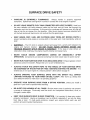
9. Remove the tiller handle from the frame by cutting all plastic tie-wraps that have
not been trimmed.
10. The 3/8"x 2-1/2" bolt ind icated by the arrow in the figu re below is the pivot point
for the Adjustable/Floating handle. Remove the bolt and insert the handle into
the engine-mounted handle bracket. Reinstall the bolt into the bracket, passing it
through the hole at the end of the handle. Be sure to include the wire loom to
secure the cables as it was shipped. Install the washer and nut and tighten the
nut firmly or until a slight amount of drag can be felt while pivoting the handle up
and down from the grip. Attach the safety kill switch wires to the mating
terminals on the engine.
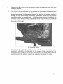
11. Route the throttle cable through the opening near the lower rear section of the
engine and attach the throttle cable to the )engine linkage as shown in the
following photos on page 3. A flat spot near the end of the black cable should be
visible, indicating the position where it was originally clamped at the factory.
2
Kohler 25-27 HP
29-35 HP Vanguard
Vanguard 18-23 HP
Check to ensure that the throttle linkage on the engine moves throughout its full
range when the throttle lever is depressed and that it returns to the idle position
when released.
For added safety, a stainless steel throttle return spring has been installed during
factory assembly. This spring returns the throttle linkage to idle position when
the squeeze lever is released. To ensure that the throttle operates smoothly,
periodically lubricate the throttle linkages with a WO-40 type spray lubricant.
3
12.
Bolt the engine to the transom as described below.
ATTENTION:
The Go-Devil Surface Drive engine
MUST BE BOLTED TO THE TRANSOM!!!!!
Failing to do so will cause the transom clamp to
loosen while trailering, allowing the engine to
possibly fall off of the transom!!!!
BOLTS MUST PASS THROUGH A STRUCTURAL
CROSS-MEMBER OF THE TRANSOM!!!
(channel, tube, rib, etc.)
Looking from the rear of the engine, notice that the transom clamp has two
horizontal rows of holes. Either the two upper or two lower holes need to be used
to secure the engine to the transom . Four holes are provided to accommodate
various transom designs.
Using a 3/8" drill bit, drill through the lowest hole pattern on the bracket which
would allow the bolts to pass through a structural cross-member of the transom.
Install the two supplied 3/8"x3" bolts, washers and nylon insert nuts. For Go
Devil boats, the engine should be bolted to the transom using the two top holes.
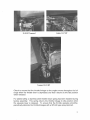
13. Tie a rope to the rib in your boat under the hand grip
of the Surface Drive and put a loop in the rop~. Slip
the loop over the handle to hold the engine in a
neutral position while the handle is in its lowest
position. The rope should be short enough so that the
engine can idle with the prop out of the water. If the
handle is used often in a higher fixed position, it may
be necessary to attach an additional longer rope along
side the initial one or use a rope long enough so that it
can be tied securely at various lengths.
4
14. Connect the battery cables to the battery. Attach the red cable to the positive (+)
side of the battery and attacll the black cable to the negative (-) side of the
battery.
The battery should be kept in a covered battery box secured to the floor of the
boat and away from gasoline vapors.
15. We recommend using a good nylon
rope to tie your boat instead of a boat
strap. Tie the rope to the trailer frame
on one side of the boat even with the
hand grip. Bring the rope over the
boat and make a wrap around the
hand grip on the Surface Drive, then
tie a loop in the rope before the rope
comes down the side of the boat.
Bring the rope around the trailer
frame and back up to tile loop, cinch
the rope tight and tie it off.
This procedure will hold your boat as tight as any boat strap and will secure your
Surface Drive so it will not bounce when trailering . We also recommend that you
tie a red flag to the tail end of the Surface Drive when towing your boat down the
highway.
5
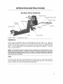
OPERATION INSTRUCTIONS Surface Drive Features Industrial Engine
/
Adjustable/Floating Handle
/
S7zeThmttle
Pressure
Lubricator
\
Kill Switch
Skeg
Surface Propeller
Hand Grip
Transom Clamp
Adiustable Trim Tabs
ENGINE OIL
Fill the engine crankcase with the recommended amount and type of oil. With the
engine held perfectly level, check the oil level with the dip stick. Use a high detergent
motor oil of the same viscosity you are using in your car or truck for that time of the
year. In warm temperatures we recommend to use straight 30 weight oil. This will
reduce oil consumption.
Notice: For 23 Vanguard models it is important that the crankcase is not over filled with oil. Over
filling the crankcase will cause a decrease in vacuum at high I speed, preventing the carburetor
from supplying an adequate amount of fuel to the engine. When this happens, the engine will
starve for fuel and temporarily lose performance. Ensure that the engine oil level does not exceed
the full level line on the dipstick.
FUEL
Fill the fuel tank with clean, fresh gasoline from a clean fuel can. Connect the fuel line
from the engine to the fuel tank and squeeze the primer bulb until firm. The tank must
have a vent and the vent must stay open during operation.
6
BASIC OPERATION Launching
When launching your boat always leave the handle rope secured in the neutral position
(shaft horizontal). This also applies when starting the engine.
Before starting the engine on the water, always put on your life vest as you would in any
boat with any engine.
Attach the safety kill switch lanyard to your belt loop or wrist.
Starting the Engine
ALWAYS check engine oil level before starting!!
WARNING!! Never run the engine in an enclosed area! Exhaust contains poisonous carbon monoxide gas that may cause a loss of consciousness and/or death! To Start the engine, first pull the choke rod to the choke position. The engine is
equipped with a mercury tilt switch so the shaft must be in a level position with the prop
out of the water for the starter to engage. Tilt the engine forward into the boat and turn
the key to the start position. It may be necessary to run the engine on choke for a few
seconds until the engine warms up. You should run the engine for at least 10 minutes
to ensure that it runs properly. If the engine runs rough after warm up, the carburetor
may need adjustment. (Refer to the engine Manual.)
To Stop the engine, release the throttle and allow the engine to idle for a few seconds.
Turn the key switch to the OFF position.
EMERGENCY STOP! The engine may be stopped ~t any time by pulling and detaching
the emergency kill switch lanyard from the kill switch. Note: It is the operator's
responsibility to ensure that the kill switch operates properly before each use.
CAUTION! - Lowering the propeller into the water at high engine rpm may cause a
standing operator or passenger to lose balance or be ejected from the boat. ALWAYS
ALLOW THE ENGINE TO COME TO IDLE BEFORE LOWERING THE PROPELLER
INTO THE WATER!
7
Low Speed Operation
As described before, let the engine warm up for a few minutes. Holding the handle
carefully, remove the handle rope and get a feel for the balance of the engine.
Neutral position is acquired by lifting the prop out of the water. While the engine is
idling, lower and lift the prop into and out of the water. Get used to low speed
maneuvering and docking the boat before attempting to increase speed .
For the first time operating your new Surface Drive engine, turn the trim adjustment
knob counterclockwise until the prop and cavitation plate can be fully submerged while
the boat is floating at rest. Under normal conditions the trim can be adjusted for high
speed performance and need not be changed while idling or getting back up on plane.
Steer the engine slowly to avoid getting water into or overturning the boat. The Go-Devil Surface Drive engine is better suited for wider bottomed boats (48" or wider). Use extreme caution- even while idling -when making sharp turns on narrow boats. To turn the boat around in a tight situation, allow the boat to nearly come to a complete
stop. While the engine is idling with the prop out of the water, turn the engine all the
way to one side and lower the prop into the water slowly. Most boats will turn in their
own length when this is done.
TIP! - Turning left at low speed requires less reach due to the handle being on the left
side of the engine. When reversing direction from rest or idle speed, set up to turn left
whenever possible. This will become instinctive with time.
High Speed Operation
As its name implies, the Go-Devil "Surface Drive", uses a surface piercing propeller.
The surface propeller is designed to be run primarily with a fraction of each blade
breaking the surface of the water with each revolution. To get maximum performance
from the engine, propeller depth can be fine tuned using the manual trim.
The manual trim mechanism is a standard feature on all SD models. The trim is simply
a bottom stop on the tilt axis of the engine which allows the engine to tilt upward freely
when an underwater obstacle is struck.
Manual Trim Adjustment
WARNING!! - The trim knob is angled outward and away from a pinch point between
the engine and transom bracket. DO NOT PLACE HANDS BENEATH THE ENGINE
WHILE IT IS RUNNING!!! If the skeg or prop strikes an obstruction while underway,
the engine may tilt violently and cause injury. continued on next page ....
8
With the boat floating at rest, set the trim low enough to fully submerge the propeller
and cavitation plate below the waters surface. After getting up on plane and to full
throttle, take notice of the propeller depth.
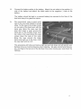
Since the SD engine is a balanced drive, the prop may initially have a tendency to lift up
and surface too high at top speed without being held by the trim mechanism. If the prop
surfaces too high, a large amount of vibration will be felt at the handle as the prop
blades "slap" the surface of the water. If this happens, bend both trim tabs upward
slightly on the rear with a large crescent wrench as shown in the figure below. For
maximum performance and comfort, you should be able to relax the weight of your arm
and hand comfortably while holding the hand grip at full speed.
If the trim tabs are adjusted properly,
the prop should stay down firmly until
the engine is trimmed up to the
desired depth. To adjust the trim while
underway, lightly push down on the
handle to free the trim and turn the
trim knob Clockwise (~) to trim up and
Counterclockwise (~) to trim down.
Trim the engine up until maximum
performance and comfort is achieved.
For the average boat and engine
combination, the prop should be run
with approximately 1/3 of its diameter above the surface. Different hull designs and
horsepower to weight ratios will affect optimum propeller depth and performance while
on plane.
If necessary, the drive ratio may be reduced to accommodate extremely
large hulls and loads.
An engine mounted tachometer/hour meter is a highly recommended accessory since it
allows you to view both engine rpm and total run time. Maximum performance will
generally be achieved between 3400-3800 RPM ~ince the engines make maximum
horsepower within this range.
9
LUBRICATION ENGINE LUBRICATION
CHECK ENGINE OIL BEFORE EACH USE. We recommend changing engine oil every 50 hours
or yearly. When changing oil, run the engine to heat the oil before draining . When changing the
oil filter always fill the filter with oil before installing . Fill crankcase and then prime the oil pump by
spinning the engine with the electric starter for about 10 seconds with the safety kill switch in the
kill position . Start the engine and let it idle for a few minutes before speeding up.
Lubricate the engines throttle linkage as needed with a WD-40 type spray lubricant. This may
or may not be necessary depending on environmental conditions. An occasional spray will help
keep the throttle functioning smoothly.
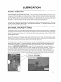
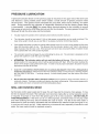
EXTERNAL GREASE FITTINGS
The Surface Drive unit has 3 external grease fittings which require periodic lubrication . One fitting
is located on the drive tube and the other two are located on the tilt and steering axes (see photos
be/ow). We recommend using a #1 or #2 marine grade waterproof grease such as AQUA-LUBE
to lubricate all fittings .
Grease the steering and tilt axes after every 10-20 hours of run time. Any more often will be
excessive and messy. In addition to lubricating the fittings, apply a small amount of grease yearly
or as needed to the transom clamp bolts and manual trim lead screw.
The fitting shown in the figure on the right below is used for lubricating the prop shaft and lower
bushing and seal system. A pressure lubricator shown to the left of the fitting feeds grease to
the system as needed and allows for heat expansion inside the drive tube . See the following
section on PRESSURE LUBRICATION on page 11 for proper lubrication and maintenance .
The drain plug shown is used to check for water leakage inside the frame housing . This should
be checked after the first few hours of run time, including the first few hours of initial engine
break-in and again each time the panels
are removed and
reinstalled. While the engine is out
.
I
of the water, remove the plug and tilt the engine back so that any water inside the housing will
drain out of the drain hole . If water comes out when checked , the panels should be resealed .
Grease Fittings
10
PRESSURE LUBRICATION
A pressure lubricator shown on the previous page is mounted on the upper end of the drive tube
and features a spring loaded piston which creates a small amount of grease pressure inside
the drive tube . This grease volume lubricates the prop shaft, lower bronze bushing, and lower
seals. During assembly the lubricator is intentionally oriented so that the factory grease fitting
is inaccessible. Lubricate ONLY the grease fitting mounted adjacent to the lubricator to ensure
that grease is fed into the drive tube and not just into the lubricator. Pumping grease through this
fitting will fill both the drive tube and the lubricator.
• Visually inspect the position of the lubricator piston before and after each use.
• The lubricator should be kept about 0/. full so that grease consumption can be easily monitored. The
lower drive system should use up very little or no grease at all when functioning properly.
• If the grease level does not seem to change after several hours of run time, pump grease into the drive
tube until the piston starts to rise . This ensures that the lubricator piston is not "stuck" and giving a
false impression that the tube is full. If the lubricator and drive tube are properly filled, the piston should
move upward after only a few pumps of grease.
• The lubricator cannot be damaged by over-lubricating the drive unit. The lubricator is designed so that
grease will expel from under the cap if over-filled.
• ATTENTION: The lubricator piston will not reach the bottom of the cup. When the piston is at its
lowest position, the visual grease column will be approximately 3/8" high. When the piston reaches this
level it will no longer supply grease to the tube. In order to insure proper lubrication, the piston must be
kept above this level at all times.
• IT IS THE CUSTOMERS 'S RESPONSIBILITY TO CHECK AND INSURE THAT THE LUBRICATOR IS
WORKING PROPERLY!! Remove and clean the lubricator yearly to ensure that it is working properly
and the piston is not stuck. If working properly, it should expel grease from the bottom hole when
removed.
• Do not clean the lubricator with a petroleum solvent such as gasoline, varsol, kerosene, thinner, or
carburetor cleaner. Petroleum solvents will destroy the plastic components. Wipe excess grease with
paper towels and clean components with mild dishwashing liquid.
SEAL AND BUSHING WEAR
As the lower and/or upper seals start to wear, the unit may start to consume more grease. It may
be time to replace the seals if the lubricator ever becomes empty after a normal operation period
or requires 10 pumps or more from the grease gun to filion two occasions. DO NOT DELAY
THIS PROCEDURE!!I If the drive unit is run without grease, premature wear on the prop shaft
and lower bushing will occur and will elevate the cost of repair. The life of the lower seals is
determined by how the shaft is lubricated and how abrasive the material is that the engine is run
in, such as mud , sand, and silt. Under extensive or commercial use, especially in brackish or salt
water, the lower seals should be replaced annually.
11
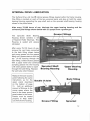
INTERNAL DRIVE LUBRICATION
The Surface Drive unit has 4 internal grease fittings located within the frame housing .
One fitting is located on each of the two universal joints and also on both the upper
bearing housing supporting the prop shaft and on the sprocket shaft bearing housing
shown in the photo below.
After every 75-100 hours of use, lubricate the upper bearing housing and the
universal joint fittings shown below with 2-3 pumps from a grease gun.
Grease Fittings
The Sprocket Shaft Bearing
Housing shown contains a set
of Tapered Roller Bearings . This
Housing is sealed and grease
lubricated.
After every 75-100 hours of use,
remove the vent tube connected
to the barb fitting shown below
and pump grease into the grease
fitting until grease starts to exit the
top of the housing through the
barb fitting. Collect excess grease
with a paper towel and continue ......_ _ _-+__________+__----'
pumping grease into the housing
Sprocket Shaft
Upper Bearing
until clean grease starts to expel
Bearing Housing
through the barb fitting . Replace
Housing
the vent tube when finished.
Replace the lower access
panel following the same
instructions as for the
Double U-Joint
upper panel described
on the bottom of page .
15. Add an additional
amount of Silicone to the
corner areas where the
bend in the lower access
panel mates to the frame.
Panels must be sealed
properly to keep water
out of the frame housing.
Grease Fitting
~
Barb Fitting
A
/
Sprocket
12
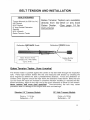
BELT TENSION AND INSTALLATION TOOLS REQUIRED
Torque Wrench (to 250 Lbs.-In.)
3/8" Socket
9/16" Socket
6" long Socket Extension
Ratchet
9/16 Wrench
Gates Tension Tester
Gates Tension Testers are available directly from Go-Devil or any local
Gates Dealer. (See page 14 for
Instructions)
Deflection FORCE Scale
Deflection DISTANCE Scale
•
\
•
-
-
~-~~
• •.•• ~- --
.--------.
.:
.'1
{q~t*':"
• '.'
,.4..,4
~ '! ~ Gates Tension Tester
(Product No. 7401-0076)
- Up to 30 Ibs.
/
Sliding Rubber
"0" Ring
Gates Tension Tester... How it works!
The tension tester is pushed against the center of the belt width through the inspection
hole. Pencil type tension testers like this one mea~ures belt tension by showing the
force required to deflect the belt a predetermined distance. Force and deflection on
Surface Drive Engines should be kept within the tolerance listed below. Belts that are
run too loose will cause an increase in driveline vibration resulting in reduced belt life.
When tensioning, adjust to the high end of the given tolerance to allow for belt stretch.
Never tension belt more ' than specified! Over-tensioning the belt may cause
premature wear or damage to the engine and drive unit bearings.
Standard 16" Transom Models
Force = 11-15Ibs.
Deflection = 1/4"
20" High Transom Models
Force = 9-13 Ibs. Deflection = 1/4" 13
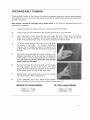
CHECKING BELT TENSION Checking Belt Tension on the Surface Drive does not require removal of the rear access panels.
An inspection hole on the side of the frame is provided to inspect and check belt tension from
outside of the frame.
Belt tension should be checked every 30-50 hours of run time as described below and
readjusted if necessary.
1. Locate the black hole plug on the side of the frame behind the engine.
2. Carefully slip a knife blade behind the plug flange and pry it out of the hole.
3. Use a flashlight to look inside the hole and locate the belt. When using the tension
tester, force must be applied to the belt by pushing the tester in the center of the belt
width. The inspection hole mayor may not be centered on the belt width.
4. Touch the tester against the center of the belt width
as shown to the right.
To measure deflection,
compare the inch deflection scale on the tester to the
outside edge of the hole with the tester just touching
the belt.
5. Next, push the tester against the belt to deflect it the
distance described above by viewing the deflection
scale relative to the outside edge of the inspection
hole. Be sure to use the inch scale and not the
metric scale on the tester.
6. Remove the tester from the hole and view the sliding
The force
applied to deflect the belt is indicated by the location
of the bottom of the"O" ring on the force scale.
"0" ring location on the force scale.
7. Repeat steps 4-6 several times or until you achieve
the same result for each measurement.
8. If the measured force falls below specs shown
below, retension the belt as described on the following page (15).
Standard 16" Transom Models Force = 11-15 Ibs.
Deflection = 1/4"
20" High Transom Models
Force = 9-13 Ibs. Deflection = 1/4" 14
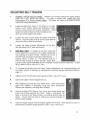
ADJUSTING BELT TENSION 1. REMOVE UPPER ACCESS PANEL: Remove all 1/4" bolts holding the Upper access
panel with a 3/8 socket and ratchet. The panel is sealed with Loctite 598 High
Performance RTV Silicone Gasket Maker. The panel will need to be pried from the
frame with a large screwdriver.
2. Locate the 3/8" bolts shown in the photo to the right.
Using a 9/16" socket, ratchet and extension, loosen
the top 4 bolts around the engine crankshaft. Hand
tighten the bolts to allow the frame to slide up and
down but remain against the engine.
3. Loosen the lower 4 bolts using the ratchet and 9/16"
wrench. Snug the bolts as done for the upper bolts to
allow the frame to slide up and down.
4. Loosen the Upper Tension Adjustment nut on the
jack bolt using a 9/16" open end wrench.
5. NEW BELT ONLY - If installing a new belt, loosen the
Lower adjustment nut and turn the Upper adjustment
nut clockwise to loosen the belt. Remove all four of
the 3/8" bolts securing the sprocket shaft bearing
housing shown on page 12. The sprocket unit can
then be lifted enough to change the belt. Apply Blue
Loctite to bolts and reinstall them with the new belt in place around the sprocket. Torque
all four bolts to 250 In.-Lbs. (21 Ft.-Lbs.)
6. To increase belt tension, turn the Lower Tension Adjustment nut counterclockwise until
the proper tension is achieved as indicated by the tension gauge instructions listed on
page 14.
7. Tighten all 8 of the 3/8" bolts shown above to 250 In.-Lbs. (21 Ft.-Lbs.)
8. Tighten the Upper Tension adjustment nut.
9. After tightening all bolts and nuts listed above, check belt tension
again and readjust if necessary using the same procedures.
Replace the inspection hole plug when finished.
10. Remove existing RTV Silicone from frame and access panel and
insure that mating surfaces are clean. Apply a continuous 1/8"
bead of silicone to the frame surface, surrounding all bolt holes as
shown. Ensure that the bead is continuous around perimeter to
prevent water leakage.
11. Install the Upper Access Panel and lightly tighten the 1/4"bolts. Allow Silicone to cure for
several hours and then torque all bolts to 125 In.-Lbs. (10 Ft.-Lbs.)
15
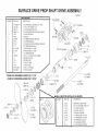
SURFACE DRIVE PROP SHAFT DRIVE ASSEMBLY 10/03/05
QUANITY
or
2
1
or
3
2
I
PARTS REQUIRED
DESCRIPTION
PART NO.
**LSHS15-78
14X14SS
LHC-78
LHFB-78
78SC
4B-78
UBH-78
UB-78
5-78-8
7-78
6-18-24SD
6-35SD
14
3812SSS
10
lOA
7/8" LOWER SEAL HOUSING 1.5" SEAL
1I4"X1I4" SET SCREW 18-8
7/8" LOWER HOUSING CAP
7/8" LOWER HOUSING FLANGE BUSHING
7/8" SCRAPER SEAL 7/8" SEALS
7/8" UPPER BEARING HOUSING
7/8" UPPER BEARING
7/8" LOWER BUSHING W/SPIRAL GROOVE
7/8" UPPER GREASE SEAL
7/8" PROP SHAFT 16-24HP
7/8" PROP SHAFT 25-35HP
114" UNDERSIZE KEY 3/8"-16 x 112" SOCKET SET SCREW UNIVERSAL JOINT
CENTER YOKE 7/8" SPLIT YOKE
1" SPLIT YOKE
3/8"X1-1I2" NF BOLT
3/8" NF LOCKNUT
lIB 9-8A #38112NFG5 #38LN.NF **LSHS15-34 HOUSING LENGTH IS 1-11/j6"
LSHS15-78 HOUSING LENGTH IS 1-13/16"
78SC OR
LHFB-78--
9-8A 1" Split Yoke
----
UB-78
3812SSS
#38LNNF
---7-78
---21
---UBH-78
lIB 7/8" SplitYoke
14-~
~
WIE
21-78
~
6-18-24SD
(l6-24HP)
---5-78
---14X14SS
6-35SD
(25-35HP)
---LSHS 15-78
SEALS MUST BE INSTALLED AS SHOWN
QUANITY
BW-15
1A2-78
~~
<
\
2-11SD
(18-24HP)
1A4-78
\\
/
2-12SD
(25-35HP)
2
or
PART NO.
DESCRIPTION
LUBE
lA4-78 lA3-78 lA2-78 BW-78
211SD
212SD
lAI-78
21
21-78
PRESSURE LUBRICATOR
7/8" NYLON INSERT JAM NUT
7/8" LOCK WASHER
7/8" REAR JAM NUT
7/8" BRASS WASHER
11" PROPELLER (l8-24HP)
12" PROPELLER (25-35HP)
7/8" FORWARD JAM NUT
114"-28 GREASE FITTING
I18"-NPT GREASE FITTING
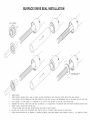
SURFACE DRIVE SEAL INSTALLATION 2
3
4
6
7
SEAL ORIENI'I<DI
«~C
0
\"'oC
AO
o
5
AO «~C
LONER HOUS ING CAP HAS
LEFT HAND THREADS
\"'oC0
~
o
1. GREASE SEALS.
2 . INSERT PLASTIC SLEEVE INTO A SEAL AS SHOWN IN ABOVE ILLUSTRATION WITH THE SEAL SPRING FACING THE SEAL HOUSING.
PUSH SLEEVE OVER THE THREADS ON THE SHAFT THEN SLIDE THE SEAL OFF ONTO THE UNTHREADED PART OF THE SHAFT AND INTO THE SEAL
3. USE AT LEAST A 6' LONG PIECE OF 1" SCHEDULE 40 PVC PIPE TO TAP THE SEAL ALL THE WAY INTO THE HOUSING.
4. REINSERT THE PLASTIC SLEEVE INTO THE SEAL AND REMOVE IT TO RELEASE ANY AIR PRESSURE THAT MIGHT HAVE ACCUMLATED DURING INSTI
5. INSERT PLASTIC SLEEVE INTO SECOND SEAL.
INSTALL SECOND SEAL WITH SEAL SPRING FACING AWAY FROM THE SEAL HOUSING.
6. TAP SEAL ALL THE WAY INTO THE HOUSING WITH THE PVC PIPE SO IT SEATS FIRMLY AGAINST THE FIRST SEAL.
7. SCREW ON SEAL HOUSING CAP BY TURNING IT COUNTER CLOCKWISE (LEFT HAND THREADS) AND TIGHTEN IT WITH A 1-5 /8" WRENCH OR CRESC
SERVICE RECORD
EI\IGINE MAKE _
_
_
_ _ _ _ _ __
VALVE CLEARANCE:
EI\IGINE MODEL # _ _ _ _ _ _ __
INTAKE _
OIL FILTER # _ _ _ _ _ _ _ _ __
EXHAUST _ __ _ _ _ _ _ ___
FUEL FILTER # _ __
_ _ _ _ __
_ _ _ _ _ __
SPARK PLUG # _ _ _ _ _ _ _ __
OIL CHANGE OIL CHAI\IGE
DATE
_ __
HRS
DATE
SERVICE WORK PERFORMED HRS SERVICE RECORD ENGINE MAKE _ _ _ _ _ _ _ _ __
VALVE CLEARANCE:
ENGINE MODEL # _ _ _ _ _ _ __
INTAKE _ _ _ ____
OIL FILTER # _ ____
EXHAUST ____________
_
_______
FUEL FILTER # _ _ ____
_
_ __
_ _ __
SPARKPLUG# _ _ ____________
OIL CHANGE OIL CHANGE
DATE
_
HRS
DATE
SERVICE WORK PERFORMED HRS Warranty This warranty replaces any warranties before June 1, 2007
Go-Devil Manufacturers of Louisiana, Inc. will repair or replace any
components, on the Go-Devil drive unit that we manufacture at no charge for a
period of two years that are defective in materials or workmanship. Transportation
charges on parts submitted for repair or replacement under this warranty must be
borne by the owner of the unit. This warranty does not cover normal wear, abuse,
neglect, or failure due to the elements of nature, such as salt water corrosion. Wear
on shaft and/or bushing due to the lack of lubrication will not be covered by this
warranty! See your Service Manual for the proper lubrication instructions.
Engines on our products have a two year engine warranty. Engine warranty
can be handled through any small engine dealer in your area that is an authorized
warranty service dealer for the brand of engine that you have on your unit. Go
Devil Manufacturers of Louisiana, Inc. is authorized to warranty all the engines
that we sell on our products. In many cases, we can expedite a repair by sending
the part to you, because most warranty repairs are as simple as replacing a simple
part. You will however, be required to return the defective part to us. At that
point, we will file the warranty claim directly t<D the engine manufacturer at no
charge to you.