1
Inc.
Web: http: // www. pearl - hifi . com
E-mail: custserv @ pearl - hifi . com
❦
Perkins Electro-Acoustic Research Lab, Inc.
86008, 2106 33 Ave. SW, Calgary, AB; CAN T2T 1Z6
Ph: + .1.403.244.4434 Fx: + .1.403.245.4456
Engineering and Intuition Serving the Soul of Music
Please note that the links in the PEARL logotype above are “live”
and can be used to direct your web browser to our site or to
open an e-mail message window addressed to ourselves.
To view our item listings on eBay, click here.
To see the feedback we have left for our customers, click here.
This document has been prepared as a public service . Any and all trademarks
and logotypes used herein are the property of their owners.
It is our intent to provide this document in accordance with the stipulations with
respect to “fair use” as delineated in Copyrights - Chapter 1: Subject Matter and
Scope of Copyright; Sec. 107. Limitations on exclusive rights: Fair Use.
Public access to copy of this document is provided on the website of Cornell Law School
at http://www4.law.cornell.edu/uscode/17/107.html and is here reproduced below:
Sec. 107. - Limitations on exclusive rights: Fair Use
Notwithstanding the provisions of sections 106 and 106A, the fair use of a copyrighted work, including such use by reproduction in copies or phono records or by any other means specified by that section,
for purposes such as criticism, comment, news reporting, teaching (including multiple copies for classroom use), scholarship, or research, is not an infringement of copyright. In determining whether the use
made of a work in any particular case is a fair use the factors to be considered shall include:
1 - the purpose and character of the use, including whether such use is of a
commercial nature or is for nonprofit educational purposes;
2 - the nature of the copyrighted work;
3 - the amount and substantiality of the portion used in relation to the copyrighted work as a whole; and
4 - the effect of the use upon the potential market for or value of the copyrighted work.
The fact that a work is unpublished shall not itself bar a finding of fair use if such finding is made
upon consideration of all the above factors
♦
PDF Cover Page
♦
♦
Verso Filler Page
♦
♦ PRECISION INSTRUMENTS FOR TEST AND MEASUREMENT ♦
Type 1644
Megohm Bridge
User and Service Manual
Copyright © 1988
IET LABS, INC.
formerly manufacturer by
GenRad
www.ietlabs.com
534 Main Street, Westbury, NY 11590
TEL: (516) 334-5959 • (800) 899-8438 • FAX: (516) 334-5988
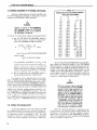
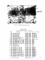
Specifications
Resistance Range: 1 kO to 1000 TO (10J to 10'5 0) in ten ranges.
Accuracy: 101 0 to 10'0 0, ±1%. After self-calibration: 10'0 to
10'2 0, ±1%*; 10'J 0, ±2%; 1014 0, ±10%; 10'� 0, ± one scale
division.
L\R% Dial: ±5% range; accurate to :t:O.2% or, for small changes,
to :t:O.1%.
Test Voltage: Voltage accuracy is :t:3% :to.S V.
Fixed Vol ta ge s "
10
Minimum Unknown R
Minimum Test
Voltage for 1 %
Resolution:
for approx 1-mm
meter deflection
*
At high voltages;
see above.
20
50
100
200
500
1000
3
7
20
50
150
500
V
Max R.
Volts
100 G or less
100 G
IT
lOti
10'2
10'J
10
100
200
V
Power Required:
105
mA,
to 125 or
10-50 V; <10
210
mA,
100-1000 V.
to 250 V, 50 to 400 Hz, 13 W.
Mounting: Flip-Tilt Case
Dimensions (width x height x depth): Portable model, 12=¥4 x 121/2
X 7¥4 in. (325 x 320 x 200 mm): rack model, 19 x 121/4 x 5 in.
(485 x 315 x 130 mm).
Weight: Net, 19 Ib
(9
kg); shipping, 31 Ib (14.5 kg).
kO
Multiplier Setting
1% accuracy is obtainable at 10
Short-Circuit Current: <15
Catalog
Number
De sc ript ion
1644-A Megohm Bridge
1644-9701
Portable Model
up to 10'1 0;
U.S. Patent Numbers 0187,740 and 2,966,257.
... Any voltage between 10 and 1000 V may be obtained using an external
resistor.
SYMBOL INDICATES TERMINALS WHICH MAY HAVE
A POTENTIAL OF 11100 VOLTS PRESENT,
SECTION
1
INTRODUCTION
&
WARNING
High voltage may be present at any of the
red binding posts, depending on the
switch settings. Lethal energy may be
stored in a capacitance connected to the
instrument ALWAYS SET THE FUNCTION
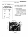
1.2 CONTROLS AND INDICATORS.
Table 1-1 (on page
2) lists the controls and con
nectors on the panel and sides of the Type 1644-A
Megohm Bridge.
SWITCH TO DISCHARGE BEFORE CON
NECTING OR DISCONNECTING THE UN
KNOWN COMPONENTS.
1.3 SYMBOLS.
The following abbreviations are on the RESIST
ANCE MULTIPLIER dial of the Type 1644-A Megohm
B ridge:
1 kD
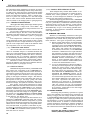
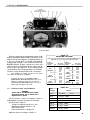
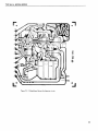
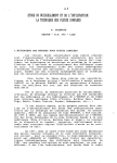
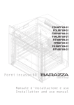
1.1 PURPOSE,
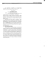
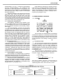
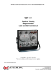
The Type 1644 - A Megohm Bridge (Figure 1 -1)
measures resistance from 103 to 10150hms. It is
useful for m easurements of resistors, of insulation
resistance on components and machinery, for resis
tivity tests on samples of insulating material, and for
leakage-resistance measurements on capacitors. The
vernier (�R%) dial permits accurate measurements
of voltage and temperature coefficient of resistance.
The voltage applied to the unknown may be set from 10
volts to 1000 volts.
1 MD
1 GD
1 TD
103 D
6
10 D
9
10 D
12
10 D
3
10 kD
6
10 kD
9
10 kD
TYPE 1644-A MEGOHM BRIDGE
3
13
11
10
9
6
F iqure 1.
Type 1644 Megohm Bridge.
----,
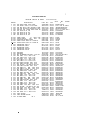
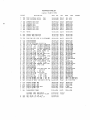
,.--- TABLE ,1-1 -CONTROLS AND CONNECTORS
Fig.
Ref. No.
Type
Name
Function
5-position rotary control
COARSE ZERO
Continous rotary control
Function
Turns in-strument on, selects DISCHARGE,
CHARGE-ZERO, or MEASURE function.
(See paragraph
2
2.2.)
For coarse zero adjustment of detector.
3
FINE ZERO
Continous rotary control
For sensitive zero adjustment of detector.
4
VOLTAGE ON
8 -position rotary control
Selects magnitude of internal voltage applied
UNKNOWN
5
RESISTANCE
b
R
MULTIPLIER
7
SENSITIVITY
8
L\R%
to the unknown or connects an external voltage
source.
Selects the measurement range.
Continous rotary control with
Balances bridge.
Continous rotary cORtrol
Adjusts the sensitivity of the detector circuit.
(See paragraph 2.4.)
dial
{
(See paragraph 2.2.)
10-position rotary control
Pushbutton switch
Continous rotary control
with dial
Inserts L\R% adjustment in the measurement
(See paragraph 2.4.)
circuit.
Balances bridge over ±5% range.
3.6, 3.7, and 3.8.)
- UNKNOWN +
Pair of insulated binding posts
For connection of component to be measured.
10
Ground
Uninsulated binding post
Ground connection to instrument chassis.
11
GUARD
InsulatE
12
EXT GEN
Pair of insulated binding posts
13
EXT ADJ
Pair of insulated binding posts
9
j binding post
(See paragraph 2.1.4.)
For connection to points to be guarded, such
as shields of leads.
(See paragraph 3.4.)
For connection of an external voltage supply.
(See paragraph 3.10.)
For connection of a resistor to adjust the
voltage applied to the unknown to values
between those supplied.
2
(See paragraphs
(See paragraph 3.9.)
OPERATING PROCEDURE
SECTION
2
OPERATING PROCEDURE
2.1.4 GROUNDING THE INSTRUMENT.
2.1 INSTALLATION.
2.1.1 OPENING AND TILTING THE CABINET.
The directions for opening the Type 1644- A are
given on the handle support of the instrument.
Once
open, the instrument can be tilted to any convenient
angle, as shown in Figure 1-1.
The angle should be
To avoid electric shock the chassis must always be
connected to ground This is particularly important for
very high resistance measurements where lack of a
ground can cause difficulty. It is also advisable to
ground the panels of nearby instruments to avoid
electrostatic coupling to the detector.
chosen to give the most comfortable access to the knobs
and the best view of the meter and dials.
The instrument may be locked fully open by the
2.1.5 CONNECTI ON OF GROUNDING LINK.
same slide pins that are used to lock the instrument
closed.
Thus, the instrument can be carried in the
open position with the cover firmly in place.
The cover forms a convenient storage place for
the instruction manual and for any test data that should
be kept with the instrument.
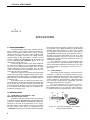
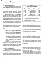
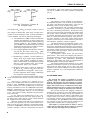
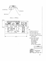
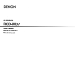
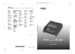
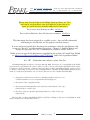
The grounding link, captive to the uninsulated
(chassis) binding post, may be connected either to the
GUARD terminal or to the - UNKNOWN terminal as
shown in Figure '2-2. The ground-to-GUARD connec
tion is preferable if the unknown is a sm:lll, separate
component, or if it is mounted in an enclosure that
should be guarded. (Refer to paragraph 3.4). However,
2.1.3 POWER CONNECTION. Any changes to line
voltage configuration must be performed by qualified
personnel
The
1644 is normally supplied
connected for
105- to 125-V, 50- to 400-Hz line voltage.
line
voltage,
if specifi ed
when ordered.
Two
fuses are supplied with the instrument; one, F501, is
a spare,two ;)'2-A SI0-810 fuses, Bussman MOL 0.2 A
or equivalent, are supplied for the 105-125-V connec
tion.
nected to the - UNKNOWN binding post and the ground
ing link connected between the - UNKNOWN post and
the chassis ground post.
The in
strument is connected for 210- to 250-V, 50 to 400
Hz
if one terminal of the unknown must be grounded or is
a large exposed surface, this terminal should be con
Tho 0.1-A Slo-810 fuses, Bussman MOL O.lA or
GUARD
- UNKNOWN-t
@m@W
UNGROUNDED OPERATION
Figure 2-2. Grounding link con
nected to the GUARD terminal
(top) and the
UNKNOWN terminal (bottom).
-
equivalent, are supplied when 210-250-V is specified.
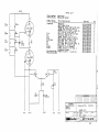
To change line voltage, refer to the note in Fig
ure 5-7. The power transformer can be reconnected
for each line voltage. If the line voltage connection is
changed, make sure the proper fuse is fitted in the
F502 holder.
inet should be changed to ensure that the instrument
is not inadvertently connected to the wrong line volt
age.
GROUNDED OPERATION
Also, the voltage legend plate on the cab
On instruments changed to 210-250 V, order a
210-250 V nameplate (PIN 5590-1665).
For a change
to 105-125 V, order nameplate PIN 5590-166 0.
Check that the proper fuse is in holder F502 and
connect the instrument,using the power cord provided.
2.2 BASIC MEASUREMENT PROCEDURE.
Many types
of measurements under
various
conditions can be made with this instrument. The fol
lOWing is the basic measurement procedure. Refer
ences are given to paragraphs that discuss each step
more fully or consider alternate procedures or special
measurements.
3
TYPE 1644-A MEGOHM BRIDGE
&
WARNING
This instrument provides a high test voltllge.
g.
Particular care should be used in the measurement of
capacitor l88kage, because LETHAL ENERGY may be
Set the function switch to M EASURE and ad
just the main R dial (and the RESISTANCE
MULTIPLIER switch, if necessary) to give a
null (meter zero). A deflection to the right
stored in the unknown capacitor. DO NOT TOUCH
THE CAPACITOR TERMINALS
WHILE
THE
"VOLTAGE APPLIED" LIGHT IS ON. ALWAYS SET
indicates that the dial setting should be in
THE FUNCTION SWTICH TO DISCHARGE BEFORE
est ranges, rezero the meter (step f) when
CONNECTING
OR
DISCONNECTING
creased. For maximum accuracy on the high
THE
the RESISTANCE
reset.
UNKNOWN COMPONENT.
h.
MULTIPLIER switch
is
The value of the unknown resistance is the
dial reading at null indication multiplied by
the quantity indicated on the RESISTANCE
MULTIPLIER dial.
Proceed as follows:
a.
Turn the function switch from OFF to DIS
CHARGE. Allow a minute or two for warmup.
b.
i.
voltage supply and to paragraph
of an external supply.)
3.10 for use
The minimum re
sistance that can be measured at each test
voltage is given in Table 2-1. Avoid changIng
the test voltage when the function switch IS
in i he MEASURE position as this will severely
overload the detector amplifier which will
then require several minutes to recover.
2.3 ACCURACY.
The bridge accuracyis ±1% between reamngs of
OoS) and 10 on the main R dial. Above a readi·ng of
llie accuracy tolerance increases
that it is
Note polarity.
a.
Set the RESISTANCE MULTIPLIER switch to
calibrated
Set the SENSITIVITY control fully clockwise
for measurements either on the highest rang
es or at low voltages.
Set it halfway (arrow
up) for other measurements. (Refer to par
f.
agraph 2.4.)
Set the function
switch to CHARGE-ZERO
and adjust the COARSE ZERO and then the
FIN E ZERO controls for a meter zero (null).
�---
TABLE 2-1 ------t
MINIMUM MEASUREMENT RANGES
Test Voltage
10 v
20 v
50 v
100 V
200 v
500 v
1000 V
4
or
if the
ambient temperature
has changed appreciably (refer to paragraph
5.4.1);
b. reduced sensitivity reduces the accuracy
the two highest ranges if Jess than
the desired range (if it is known).
e.
the three highest ranges will not necessarily
be 1 % accurate if they have not been recently
connection, refer to paragraph
d.
±2o/c at 20 and ±10% at 100. An indication of
500 or 00. There are
three exceptions to this:
(For grounding-link
2.1. 5; for re
mote measurements, refer to paragraph 3.5.)
10,
proportionally so
1000 can be di sti nguishcd from
c. Connect the component to the U NKNOWN ter
minals.
2.3.)
Return the function switch to DISCHARG E
and then remove the component measured.
Select the desired test voltage with the VOL
TAGE ON UNKNOWN switch. (Refer to par
agraph 3.9 for external adjustment of the
(For accuracy of meas
urement, refer to paragraph
011
100 volts
is applied to the unknown;
c.
on the I-TQ multiplier range, the accuracy
is 2%.
For greatest accuracy, particularly at high re
sistance values, be sure that the component to be
measured is not shunted by insulating materials with
resistance low enough to introduce error.
paragruplls 3.11 and 3.12.)
(See also
2.4 SENSITIVITY.
The high sensitivity of the internal dc null de
tector (apprOXimately 300 \lvolts/division near zero)
permits accurate measurements with low applied vol
Minimum RX
1 kQ
3 kQ
tages, for measurement on the high ranges, and for
measurements of small differences with the .6.R% dial.
For other measurements less sensitivity keeps the
pointer on scale over a greater adjustment range and
7 kQ
does not show the amplifier drift and the discontinuous
150 kQ
meter jumps due to finite resolution of the main R dial.
Balances to a precision well beyond the bridge accuracy
,/
offer no advantage, and take more time.
20 kQ
50 kQ
500 kQ
OPERATING PROCEDURE
For
maximum
sensltlVIt v,
the
mcasun:ment
should be made on the highest -range possible.
expression for the bridge output voltage is:
E
O
where
E
=
IN
The
(�%) M
(Dial Reading) (104)
� is the unbalance in percent
Mis unity except on the 100-GQand I-TQ
ranges where it is 0.1 and 0.05, respectively.
Thus, a low dial reading increases sensitivity.
With
careful zeroing, voltages as low as 50 flvolts can be
detected.
Therefore, with 10 volts applied and a dial
indication of 1, resolution is 0.05% on all but the two
highest ranges.
Note that the meter scale is nonlinear.
This
allows a wide dynamic range without adjustment of the
SENSITIVITY control and still gives high sensitivity
near null (zero). Full meter deflection is not possible
when the SENSITIVITY control is fully counterclock
wise.
TIns low sensitivity is useful for limit meas
urements on the linear portion of the scale (refer to
paragraph 3.13).
2.5 LINE-VOLTAGE REGULATION.
The accuracy of measurements accomplished
with precision electronic test equipment operated from
ac line sources can often be seriously degraded by
fluctuations
ill
primary input power.
Line-voltage
variations as much as ±15% are commonly encounter
ed, even in laboratory environments.
Although most
modern electronic instruments incorporate some de
gree of regulation, possible power-source problems
should be considered for every instrumentation set
up.
The use of line -voltage regulators between power
lines and the test equipment is recommended as the
only sure way to rule out the effects on measure
ment data of low line voltage, transients, and other
power phenomena.
5
TYPE 1644-A MEGOHM BRIDGE
SECTION
3
APPLICATIONS
3.1
RESISTOR MEASUREMENT.
The EIA standard test voltage for fixed compo
sition resistors, film resistors, and wire-wound re
sistors is 100 volts for values above 100 kQ, 10 volts
between 1 kQ and 9.9 kQ, and 30 volts between 10 kQ
and 99 kQ. (To obtain a 3D-volt test voltage with the
internal supply of the Type 1644-A, connect a 20-kQ
resistor between the EXTERNAL AD} terminals and
set the VOLTAGE ON UNKNOWN switch to 50, as
described in paragraph 3.9.)
For many types of resistors, the value measured
at some other voltage may be considerably different
from that at the standard test voltage, due to a large
voltage coefficient (refer to paragraph 3.7). In many
cases, measurements at the voltage at which the re
sistor will be used are helpful.
Resistors as low as 1 kQ may be measured easily
to 1% on the Type 1644-A Megohm Bridge. More accu
rate substitution measurements are possible using the
6R% dial if an external standard is available (refer to
paragraph 3.6).
If the resistors to be measured are small, sep
arate units, they should be measured ungrounded with
the grounding link conrtected.between the GUARD and
ground terminals. Resistors may be measured rapidly
in a production-line setup using the procedure de
scribed in paragraph 3.13.
this terminal and the chassis ground terminal (refer
to paragraph 2.1.5).
When the device to be measured
includes polarized rectifiers or capacitors, the sign
of the applied voltage must be correct.
Note that the
+ UNKNOWN terminal may be grounded with an exter
nal lead if necessary (disconnect the link from both
adjacent terminals), but errors may occur when this
connection is used to measure resistances above ap
proximately 100 MQ.
The connection of leads to large equipment also
requires some care, and the problems of a large capa
citive time constant and dielectric absorption may also
be present (refer to paragraphs 3.3.3 and 3.2.3, re
spectively).
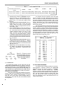
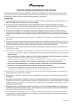
3.2.2 TEST SAMPLES.
This bridge is well suited for resistance meas
urements on samples of insulating material as de
scribed by ASTM Standard D257. This standard de
scribes in detail the techniques of both surface- and
volume-resistivity measurements.
Diagrams of sev
eral electrode configurations, applicable
and suggested precautions are given.
formulas,
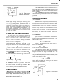
The most commonly used electrode arrange
ment for solid materials is that shown in Figure 3-1.
This configuration may be used for either surface
or volume-resistivity measurements, but for surface
3.2 INSULATION TESTING.
3.2.1 COMPONENT, MACHINERY, AND
SWITCH-GEAR INSULATION.
Insulation testing on a wide variety of apparatus
is possible with the Megohm Bridge, but different types
of devices require different precautions. When one
terminal is the case of the apparatus, or is a large,
exposed surface, this terminal should be grounded,
for both accuracy and safety, by connection to the
- UNKNOWN terminal with the link connected between
6
Figure 3-1.
Electrode arrangement for insulation
testing of sol id materials.
APPLICATIONS
measurements the gap, g, should be approximately
twice the sample thickness, t. The connection of the
electrodes to the bridge depend on the quantity to be
measured as shown in Table 3-1. The ASTM Standard
also describes other sample holders for bbth liquid
and solid materials.
Standard voltages for this test are 100,250,500,
1000, 2500, 5000, 10,000, and 15,000 volts, of which
the most common are 100 and 500 volts. The Type
1644- A Megohm Bridge will supply 100, 500, and 1000
volts directly, and 250 volts when an external resistor
is used (235 kilohms when the VOLTAGE ON UNKNOWN
switch set to 500; refer to paragraph 3.9).
When dielectric absorption is present, the main
R dial must be continually adjusted to maintain a bal
ance. To measure resistance at any given moment,
simply stop adjusting the dial at the desired time.
Thus, it is not necessary to make a reading on a mov
ing dial (fee paragraph 3.3.4).
3.3 LEAKAGE RESISTANCE OF CAPACITORS.
3.3.1 GENERAL.
&
3.2.3 DIELECTRIC ABSORPTION.
WARNING
The apparent resistance of an insulator is the
ratio of voltage applied to the current flowing through
it. Unfortunately, the current is time-dependent and
the true insulation resistance is the limiting, steady
state value.
The time-dependent currents are the simple
charging current that depends on the capacitance of
the sample and on the resistance of the voltage source,
and the current due to dielectric absorption. The sim
pIe charging current is negligible after the function
switch has been in the CHARGE-ZERO position for
a very short time (except when large capacitors are
tested; refer to paragraph 3.3.2). However, the ab
sorption current may be appreciable for minutes,
hours, or in rare cases, even days. This dielectric
absorption is the result of dipole and interfacial po
larization and ion mobility and is particularly large
for laminated materials.
A measure of the dielectric absorption is the
polarization index, which is defined as the ratio of the
resistance measured after 10 minutes to that meas
ured after one minute of electrification. Often, a single
measurement after one minute is called the insulation
resistance. Although this value may be far from the
true resistance for some insulators, it is useful for
comparison of measurements on materials with rela
tively low absorption.
3.2.4 MEASUREMENT PROCEDURE.
The procedure for measurement of insulation
resistance is the same as the basic measurement pro
cedure described in paragraph 2.2 except for charging
and dielectric-absorption considerations.
The function switch should be left in the CHARG E
position long enough to charge the sample. The time
required for simple charging is usually well under
one second except for capacitors or extremely large
samples (refer to paragraph 3.3.2).
�------
The energy stored in a capacitor
may be LETHAL.
The function
switch should be set to discharge
before you connect or disconnect
the capacitor to be measured. DO
NOT TOUCH THE CAPACITOR
TERMINALS WHILE THE "VOLT
AGE APPLIED" LIGHT IS ON.
The procedure for measurements of the leakage
resistance on capacitors is basically the same as that
for resistors except that the several effects described
in the following paragraphs become more important
as the capacitance and leakage resistance become
greater.
3.3.2 CHARGING TIME.
The function switch should be left in the CHARG E
position long enough to ensure that the capacitor is
completely charged. If it is not fully charged, the
charging current will reduce the measured value of
leakage resistance, and the charging time constant in
the MEASURE pOSition can become quite large (refer
to paragraph 3.3.3).
The charging time is limited mainly by the max
imum current of about 8 rna that can be drawn from
the power supply. Charging time is, therefore:
t
t
=
=
CV
I
=
�
8 rna
(C in Ilf) (V in volts )
3
x 10. sec
8
This time is usually less than 1 second except for
large electrolytic capacitance units. The current is
somewhat greater than 8 rna at 50 volts or less.
TABLE3-1
--------�
ELECTRODE CONNECTIONS FOR INSULATION TESTING
For Volume Resistivity
Electrode
Function
Connect to
For Surface Resistivity
Function
Connect to
#1
Guarded Electrode
+ UNKNOWN
Guarded Electrode
+ UNKNOWN
#2
Guard Electrode
GUARD
Unguarded Electrode
- UNKNOWN
#3
Unguarded Electrode
- UNKNOWN
Guard Electrode
GUARD
7
TYPE 1644-A MEGOHM BRIDGE
3.3.3 TIME-CONSTANT EFFECTS.
The time constant of the bridge-capacitor system
for the MEASURE function is the product of the capa
citance measured and the effective bridge output re
sistance, R ' given in Table 3-2. If this ploduct is
O
greater than about 0.1 second, the bridge will appear
to be sluggish and the user may adjust the bridge
beyond balance before the null - detector deflection
reverses sign. Adjustment will be easier, although
the total balance time will not be less, if you wait for
a period of several time constants between balances.
When the function switch is set to CHARGE, the
capacitor being tested is charged to a voltage that is
dependent upon the position of the R dial. This voltage
may differ from the final capacitor voltage by as much
as 1 % of the applied voltage. Th� charging or
discharging must be done with the function switch set
to MEASURE so the time required is independent of
further adjustment of the R dial.
In extreme cases, this time constant may be so
long that it is impractical to wait. An alternate pro
cedure described below makes use of the fact that the
bridge is initially at balance when the function switch
is rotated from CHARGE-ZERO to MEASURE, and
then drifts slowly off null. The direction of the null
detector drift indicates the direction that the main R
dial should be rotated to obtain the final balance.
The alternate balance procedure for measure
ment of capacitors with long time constants is given
below:
a. Set the function switch to CHARGE and allow
time for full charging (refer to paragraph
b.
3.3.2).
Rotate the function switch to MEASURE and
note the direction of the drift from zero
(di&count the small, fast deflection caused
switching phenomena).
c. Make a large adjustment in the main R dial
in the direction indicated by the null detector
(i.e., a right-hand meter deflection indicates
that the dial reading should be increased).
d. Return the function switch to CHARGE and
repeat the above steps until-a balance is
reached.
Note that the time constant is reduced if the
measurement is made on a lower range (i.e. with a
dial reading above 10) so that a lower-valued standard
is used. This, of course, gives reduced accuracy,
but high accuracy is rarely required for this type of
measurement. Also, use reduced detector sensitivity,
at least to get a rough balance.
3.3 .4 DIELECTRIC ABSORPTION.
Dielectric absorption is present to some degree
in all capacitors, but is particularly pronounced in
some impregnated paper types and is lowest in unim
pregnated polystyrene, polyethylene, and Teflo�units.
The effect of dielectric absorption is discussed in
paragraph 3.2.3. For measurements on most types of
capacitors, electrification for two minutes is common
practice.
8
-------
TABLE 3-2 -------,
BRIDGE OUTPUT RESISTANCE
Range
1
10
100
1
10
kg·
kn
kn
Mn
Mn
100
1
10
100
1
Mn
Gn
Gn
Gn
Tn
Value
Ion
100 n
1 kn
10 kn
100 kn
1
10
100
1000
10,000
Mn
Mn
Mn
Mn*
Mn*
R
O
Type
Wire -wound
Wire -wound
Wire-wound
Wire-wound
Wire-wound
Metal-film
Metal-film
Carbon-film**
Carbon-film**
Ca rbon-film**
5
5
5
15
100
1
10
100
100
500
knt
knt
knt
knt
kn
Mn
Mn
Mn
Mn
Mn
*
T network, effective value given, refer to
paragraph 3.6.3.
** Adjustable, refer to paragraph 5.4.1.
t Depends on setting of R dial.
When both appreciable dielectric absorption and
a long time constant are present, measurements be
come quite difficult because it is hard to tell which ef
fect causes the meter drift. In such cases, it is often
useful to make limit measurements. Set the. main R
dial and the RESIS TANCE MULTIPLIER switch to the
acceptance limit and wait to see if the meter deflects
to the left, which indicates that the resistance is below
the limit. A time limit should be included in the spec
ifications for such a limit measurement.
3.3.5 ERRATIC DEFLECTIONS CAUSED BY LINE
TRANSIENTS.
When leakage resistance of capacitors is meas
ured on the higher resistance ranges, the test-voltage
supply must be extremely well regulated to aVOId er
ratic meter deflections due to power-line transients.
The capacitor being measured couples the high voltage
supply to the detector so that rapid variations of less
than 1 millivolt on the high voltage supply are easily
seen. The regulation of the internal supply of the Type
1644- A is very good, but in extreme cases, when the
power-line voltage is very noisy, an external battery
should be used as the test-voltage supply (refer to
paragraph 3.10).
3.3.6 SMALL VOLTAGE CHANGES DURING
CAPACITANCE MEASUREMENTS.
In the measurement of high-capacitance, very
low-leakage capacitors (particularly polystyrene units),
a small drift in the bridge voltage supply will cause
an error in leakage measurements. This is particu
larly noticeable when the bridge indication is greater
than infinity. This condition occurs when the volt
age rate-of-change multiplied by the time constant
x R : see Table 3-2 for values of R ) is
(C
unk nown
O
O
in the order of a few millivolts. It is, therefore, most
noticeable for measurements at high voltage and on
the high RESISTANCE MULTIPLIER ranges.
APPLICATrONS
-UNKNOWN
Rx
+UNKNOWN
Rp
500 k.o.
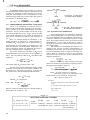
Figure 3-2.
Three-terminal
resi stance mea surement.
The + UNKNOWN terminal should be connected to
the center conductor and the shield tied to the GUARD
terminal. The lead to the - UNKNOWN terminal need
not be shielded, but if it is, its shield should also be
tied to GUARD.
The - UNKNOWN lead should be insulated unless
this terminal is grounded. All shields tied to GUARD
should be insulated if the GUARD terminal is not
grounded.
3.6
One source of this difficulty is the drift in the
internal supply during warm - up. A warm -up period
of one hour is recommended. In extreme cases, an
external supply of high stability must be used (refer
to parabrraph 3.10). Another cause of this difficulty is
ambient temperature change which changes both the
internal supply voltage and the temperature of the
capacitor being measured. If the capacitor has an
a pprec iable tern perature coefficient, a capacitor volt
age change will result.
3.4
GUARDED (DIRECT) THREE-TERMINAL MEASUREMENTS.
In many cases it is necessary to measure the
resistance between two points in the presence of re
sistance from one or both of these points to a third
point (usually ground). This third point can often be
guarded to avoid error due to shunting the unknown
with the extraneous resistances.
This is shown diagrammatically as a three
terminal resistor in Figure 3-2. Here, R is the
X
'luantity to be measured (the direct resistance) despite
the presence of R and R . If the junction of R and
B
A
A
RB is tied to guard, R is across the detector and
A
causes no error, but reduces the sensitivity by the
R
A
(see Table 3- 2 for values of R ).
factor
R
O
+R
A
o
The other extraneous resistance, R B, is across the
SOO-kQ resistor, Rp' where it causes an error of more
than 1 % ifRB is below 50 MQ. The error due to RB
Rp
x 100%.
is approximately
R
B
The guard may be used whether the GUARD or
the - UNKNOWN terminal is grounded. Note how
ever, that if the - UNKNOWN terminal is grounded,
the GUARD terminal will be at high potential. Often
the terminal to be guarded is a large chassis or case
and it is safer to ground the GUARD terminal.
-
3.5
SUBSTITUTION MEASUREMENTS.
3.6.1 GENERAL.
Substitution (or comparison) measurements can
be made with accuracy up toO .l% byineans of the �R%
dial. Substitution measurements reqUire an external
standard that is known to an accuracy substantially
better than the desired measurement accuracy. Re
sistors of high accuracy are not available in the high
megohm range but the three-terminal standard de
scribed below can be used. If only the differences
between resistors are to be determined, and not abso
lute values, the value of the standard need not be
accurately known.
3.6.2 PROCEDURE.
The procedure for a substitution measurement
is simply to measure the unknown and then the stand
ard and determine the difference between them. The
value for R is then:
x
- R
R =R +R
sm
xm
s
x
where R and R are the true values of the unx
s
known and the standard
are the measured values
and R
R
xm
sm
of the unknown and the standard.
can be
and R
The difference between R
xm
sm
most accurately determined if this difference is small
enough to be within the range of the AR% dial. The
first balance should be made with the main R dial and
then the �R% dial. The second balance should be made
using only the AR% dial (leave the R dial as set). The
value of the unknown is then:
AR%
R =R (1 +
)
x
s
100
Here, AR% is the AR% dial reading for the unknown
for the standard.
minus that
Rx
-UNK
REMOTE MEASUREMENTS.
Measurements can be made on components that are
some distance from the instrument if care is used to
Figure 3-3. Connection for
remote measurements.
prevent leakage between the connecting leads and to
avoid shock.
A convenient way to do this is' to use a
shielded cable as shown in Figure 3-3.
9
TYPE 1644-A MEGOHM BRIDGE
An alternate scheme may be used if a T nctwork
with an adjustable resistor (refer to paragraph 3.6.3)
is used as a standard. In this case, the T is used to
make the second balance and is adjusted for a null
without moving either dial of the bridge. The value of
the unknown is calculated from:
R
x
=
Rl
+
R3
+
(Rl) (R3)
R2
+
RI
_UNKNOWN
R3
T
V.
R2
(RI)(R31
R2RI+R3+ -
R3
(0 5 MQ)
R2
'
-UNKNOWN
The T or Y connection of resistors shown in
Figure 3-4a is electrically identical to the f::::,. configu
ration of Figure 3-4b. This is the familiar Y-f::l. trans
formation. If R2 is small and Rl and R3 are large,
the resistance R can be very large. R can be used
y
y
as a standard and will be very stable and accurate if'
wire-wound resistors are used for the resistors of
the T.
Such a T network should be connected to the
bridge as shown in Figure 3-2. Unfortunately, the
resistances RA and R B shunt the bridge resistor R p'
which causes an error (refer to paragraph 3.4), and
shunt the detector, which decreases sensitivity. The
loss of sensitivity limits the attainable accuracy at
low test voltages (refer to paragraph 3.6.4).
The error caused by the shunt on Rp can be
compensated for in the calculation of the resistors of
the T. For any desired value of R , the value of R2
y
should be:
500 kQ + Rl
R2 (
R - Rl - R3) R3
y
Ry
can have is Rl + R3.
y
For the most precise measurements, Rl and R3
should be the largest wire-wound units available, and
R2 should be a multi-dial decade box. If Rl and R3
are I-MQ units, then the equation for R2 becomes:
The lowest value R
=
R3
=
R2= � MQ
R - 2
y
is in megohms.
Figure 3·4b. Delta configuration
of a three ..terminal standard.
GUARD
3 .6.4 ACCURACY AND SENSITIVITY.
The bridge accuracy for substitution measure
ments using the f::l.R % dial is ±0. 1 % as long as the sen
sitivity is adequate (refer to paragraph 2.4). However,
if the two balances are well -within 1 percent of each
other, the bridge accuracy can be as good as ±0.02roo
Measurements on the main R dial can be made to
±1/4% if the difference is small and the scale is care
fully interpolated.
The accuracy of the standard must also be con
sidered in the over-all accuracy determination. To
determine the accuracy for the worst case, the toler
ance of the standard must be added to the bridge tol
erance. When a T network is used, the worst possible
tolerance of the T is the sum of the tolerances of the
separate resistors if
(Rl
105
- 20
»
Rl
+
R3
Example:
A
y
��R3)
When a T standard is used to measure very high
val ues, the sensitivity is generally the limiting factor.
The approxima te output voltage is:
Rl
(ErN) (c %) (M)
E =
x
o (Dial Reading) (104)
R + Rl
O
where [, % is the unbalance in percent
M is unity except on the 100-GQ and l-TQ
ranges where it is 0. 1 and 0.05, respectively
R is given in Table 3-2.
O
y
10 MQ, then:
R2 =
R
+ UNKNOWN
R8
RA
=
If Rl
Figure 3�4a. Y configuration
of a three�terminal standard.
GUARD
3.6.3 THREE-TERMINAL RESISTANCE STANDARDS.
where R
+UNKNOWN
lO-GO component is measured on the lO-GO
range.
MQ
A T
EIN
Table 3-3 lists the values of R2 for decade values of
Rl and R3 from 1 0 MQ to 1 TQ.
�___________________________
network with I-MO resistors is used.
=
1000
volts.
8%=0.1%.
TABLE3-3
______________________________
RESISTANCE VALUES FOR T NETWORKS
R , Equivalent Resistance
y
R2, when Rl
=
R3
=
1
R2, when Rl
=
R3
=
10
MO
MO
10 MQ
100 MQ
1 GQ
10 GQ
100 GQ
1 TQ
187.5 kQ
15.306 kQ
1 .5022 kQ
150.02 Q
1 5.000 Q*
1.5000 Q*
1.31 25 MQ 107.14 kQ
10.521 kQ 1 .0502 kQ
105.0 Q*
* Poor sensitivity
10
APPLICATIONS
Ro
E
o
=
100 MD (see Table 3-2).
1 MD
(1000) (0.1)
=
(1) (104)
x
101 MO
=
bo
zero the bridge with the function switch set
100 ,uvolts.
This would give meter deflections of about 1 mm.
If the arms of the T network were increased to
10 MD, the sensitivity would be increased by a
factor of 10.
Change the position of the VOLTAGE ONUN
KNOWN switch to the higher voltage and re
to CHARGE-ZERO, if necessary.
c.
B alance the bridge with the 6R% dial only (do
do
not change the setting of the main R dial).
The voltage coefficient is:
1) Initial balance made onI y with R dial:
6R% Dial Reading
VC
3.7 MEASUREMENT OF VOLTAGE COEFFICIENT.
2}
3.7.1 GENERAL.
Voltage Change
Initial balance made using 6R% dial:
VC
The Type 1644-A Megohm Bridge is well suited
=
Change in 6R% Dial Reading
for the measurement of voltage coefficient because of
Voltage Change
the high resolution of its 6R% dial and the wide range
of applied voltage.
The voltage coefficient of a resistor is gener
all y defined as:
VC
where
=
Rl
- .R2
-
---�-_
R2 (VI
x 100%0
-
- V2)
VI > V2
R l is the resistance at VI
3.B MEASUREMENT OF TEMPERATURE COEFFICIENT.
3.8.1 GENERAL.
The 6R% dial allows the precise measurement
of temperature coefficient, which is defined as:
R2 is the resistance at V2
VC is in % per volt.
Any two voltages may be used, but, because the
voltage coefficient is not necessarily a constant (i.e.,
the resistance is not always a linear function of volt
age), the voltages used should be specified.
A common practice is to use two voltages dif
fering by a factor of ten to one, in which case the for
mula reduces to:
VC
=
6R
R
x
1
0.9V
x 100%
where 6R is the resistance difference
R is the resistance at the lower voltage
V is the higher voltage.
The EIA Standard R S172 (Fixed Composition Resis
tors) specifies the use of the rated voltage for V in
the above formula.
If the applied voltage is high enough to cause ap
preciable power dissipation, the measurement should
be made quickly to determine the true voltage coeffi
cient and to avoid temperature effects. The EIA spec
ification suggests that the time for measurement (at
the higher voltage) be less than 5 seconds.
Most resistors have a negative voltage coeffi
where 6R is the resistance change between the
test temperature and the reference temperature
6t is the temperature change in °C from
the reference temperature.
The EIA Standards RS196 (Fixed Film Resistors)
and RS172
3.7.2 PROCEDURE.
ard RS229 (Wire-Wound Resistors) specifies meas
urements at -55°C, +105°C, and +145°C, and a refer
ence temperature of + 25°C.
Shielded leads should be used to
3.8.2 PROCEDURE.
The procedure for the measurement of temper
ature coefficient is as follows:
a.
b.
The procedure for voltage-coefficient measure
Measure the resistance of the unknown at the
lower voltage. For best accuracy use the 6R%
dial as the final balance adjustment, and note
the 6R% dial indication.
connect the
sample in the temperature chamber to the bridge to
avoid pickup and leakage (refer to paragraph 3.5).
ment is as foll ows:
a.
(Fixed Compensation Resistors) specify
that measurements be made at -15°C. The EIA Stand
cient (a lower resistance value at higher voltage),
except for semiconductor back resistance which has
a positive voltage coefficient as long as the voltage is
well below the break-down value.
R is the resistance at the reference tem-
perature
c.
With the resistor in an environment held at
25°C, measure the resistance. For best ac
curacy use the 6R% dial as a final balance
(Standard voltages should be
adjustment.
used, refer to paragraph 3.1.) Note the 6R%
dial r eading
.
Change the temperature of the resis.tor envi
ronment to the test temperature and, after
stabilization, measure the resistance again,
using only the 6R% dial. (Leave the main R
dial set as is.)
The temperature coefficient is:
TC
=
Change in !:1 R% Dial Reading
Temperature Difference in °C
11
TY.PE 1644.A MEGOHM BRIDGE
3.9 EXTERNAL ADJUSTMENT OF THE INTERNAL TEST VOLTAGE.
Any test voltage between 10 volts and 1000 volts
may be obtained. by connection of the proper resistor
between the EXTERNAL AD] terminals.
&.
WARNING
Voltage is present on the EXTERNAL
ADJ terminals unless the VOLTAGE
ON UNKNOWN switch is set to EXT or
the instrument is turned off.
To adjust the internal test voltage proceed as follows:
a. Set the VOLTAGE ON UNKNOWN switch to
EXT and connect a resistor of value Rbetween the EXTERNAL AD] terminals:
500(V
R
S
-10)(V
O
Vs - Vo
-10)
ohms
. where VS is the VOL TAGE ON UNKNOWN
switch setting
VD is the desired voltage.
It is generally preferable to set VS to the
closest value above the desired voltage, VD'
Table 3-4 gives the values of resistance to
obtain many common voltages. The external
resistor should be rated for (VD - 10) volts.
b. Set the VOLTAGE ON UNKNOWN switch to
VS and proceed with the measurement.
If a resistor of the required value is not available, a rheostat larger than this value may be used.
With the VOLTAGE ON UNKNOWN switch set to EXT,
attach the rheostat between the EXTERNAL AD] terminals, then set the VOLTAGE ON UNKNOWN switch
to VS. Set the function switch to CHARGE-ZERO and
adjust to the desired voltage using a voltmeter connected between the UNKNOWN terminals. Note that
the - UNKNOWN terminal will be negative by an amount
equal to Vo if the GUARD terminal is grounded, or
the + UNKNOWN terminal will be positive by an amount
equal to VD if the - UNKNOWN terminal is grounded.
3.10 EXTERNAL TEST-VOLTAGE SUPPLY.
An external supply for the test voltage is useful
for voltages below 10 volts, for continuous voltage adjustment, or for extreme stability for measurements
on capacitors (refer to paragraph 3.3.5). For best
stability, a battery is recommended. The maximum
voltage that may be applied to the bridge is 1000 volts.
12
.
TABLE 34
RESISTANCE VALUES FOR EXTERNAL
VOL TAGE ADJUSTMENT
v
- D
12 v
15 v
25 v
30 v
40 v
60 v
70 v
80 v
90 v
125 v
150 v
175 v
250 v
300 v
350 v
400 v
475 v
600 v
700 v
750 v
800 v
900 v
Vs
20 v
20 v
50 v
50 v
50 v
100 v
100 v
100 v
100 v
200 v
200 v
200 v
500 v
500 v
500 v
500 v
500 v
1000 v
1000 v
1000 v
1000 v
1000 v
R
1.25
5
12
20
60
56.25
90
157.5
360
145.7
266
627
235.2
355.3
555.3
955.5
4.557
730.1
1.139
1.465
1.955
4.406
kg
kg
kg
kg
kg
kg
kg
kg
kg
kg
kg
kg
kg
kg
kg
kg
Mg
kg
Mg
Mg
Mg
MQ
Set the VOLTAGE ON UNKNOWN switch to EXT,
and connect the external supply to the EXTERNAL
GEN terminals. To keep the same polarity as the internal supply, the negative terminal should be connected to the right-hand GEN terminal (that is, the
middle of the three EXTERNAL terminals). The external supply should be current-limited to protect it
from short circuits. It is also advisable to limit the
current to a safe value to avoid shock.
&
WARNING
With the externa I supply connected
as described above and the GUARD
terminal of the bridge grounded, the
negative side of this supply is at a
negative potential when the function
switch is set to CHARGE-ZERO or
MEASURE, and the positive terminal
is at high potential when the function
switch is set to discharge. With the
- UNKNOWN terminal grounded, the
negative supply of the external supply is also grounded, and the positive
side wi II be at a positive voltage
for all positions of the function switch.
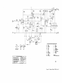
With the external generator connected as described above, the function switch will perform its
operations. Note that the external supply is disconnected but not shorted in the DISCHARG E position.
The circuit diagram for each position of the function
switch is shown in Figure 3-5.
APPLICATIONS
3.11 MEASUREMENTS ON VERY HIGH-VALUED RESISTORS.
At high resistance levels one must be sure that
3.11.1 GENERAL.
Extra precautions and careful technique are re
quired for precise measurements on very high-valued
resistors for several reasons.
The ratio - arm
resistors
three
highest ranges are carbon -film types and are not as
For accu
rate measurements on the highest ranges, the ratio
arms may be adjusted by the procedure given in par
5.4.1.
On the two highest ranges the sensitivity is re
duced by a factor of
the component being measured forms the only path
between the + UNKNOWN and - UNKNOWN terminals.
Leads should not touch each other, even if they are
insulated with high-quality material.
used for the
stable as those used on the lower ranges.
agraph
3.11.4 SHUNT LEAKAGE BETWEEN LEADS.
1/10 and 1/20, respectively, be
Shielding is the
best way to avoid leakage between leads (refer to par
agraph
3.5). If the - UNKNOWN terminal is grounded,
leakage between the + UNKNOWN terminal and ground
shunts the unknown. Therefore, ungrounded measure
ments should be used wherever possible.
3.11.5 MOISTURE ON THE UNKNOWN.
The device measured should be clean and dry.
standards (refer to
High-valued resistors should be handled only by their
paragraph
4.1). Measurements made at test voltages
100 volts are difficult.
leads to avoid surface dirt.
below
reduce the resistance value conSiderably. For exam
cause T networks
are used as
Other difficulties in measuring high valued re
Surface moisture will
ple, breathing on a glass-enclosed resistor of only
1
sistors are discussed in the following paragraphs.
GQ will cause a momentary change of several percent.
3.11.2 ELECTROSTATIC COUPLING.
3.12 MEASUREMENTS UNDER ADVERSE CONDITIONS.
On the three highest ranges the + UNKNOWN
terminal is at a very high impedance and, as a result,
a very small capacitive coupling to this terminal can
cause a large voltage on the detector input. Two sep
arate phenomena are present:
a.
Variable
The Type
1644 - A Megohm Bridge has been
designed to operate under conditions of rather high
humidity but, nevertheless, errors will occur on the
highest
capacitance to a point at a fixed
voltage will induce a transient voltage on the
ranges
approximately
when the
relative humidity is over
90%. However, the most serious errors
generally result from the effects of humidity in the
detector.
To obse rYe this, set the main R
external unknown connections.
dial to
the function switch to
tions should be taken:
00,
MEASURE,
and move your hands above the +UNKNOWN
b.
3.12.1 HIGH HUMIDITY.
terminal.
Fixed capacitance to a variable voltage will
also
induce
a
a.
Clean the
cloth.
terminal, but it should have no dc component
and will not cause a detector deflection un
in
frequency
(refer
to
b.
Use ungrounded measurements if possible.
adjacent chassis
Be particularly careful to keep the leads that
connect the bridge to the unknown separate
from each other.
The movement of the function switch and the
RESISTANCE
MULTIPLIER
ground terminal with the
connecting link.
c.
3.11.3 SWITCH TRANSIENTS.
UNKNOWN binding
That is, connect the GUARD terminal to the
paragraph
3.12.4).
between the
posts or between them and the panel.
less it overdrives the detector, or is low
enough
posts with a dry, clean
Make sure that there is no dust or
moisture
voltage on the + UNKNOWN
binding
A few simple precau
will also cause
To determine possible errors due to humidity,
transient detector voltages because of the changing
balance the bridge with no connections to the UNKNOWN
capacitance
terminals; it should balance at 00.
The most important precaution necessary under
of �hese
switch
switches
(refer
to paragraph
3.11.2) and more subtle contact phenomena.
These
fluctuations should be ignored.
humid conditions is to avoid leakage on the surface of
Rp
I k.D.
L---4-�--�0
-
0
+
UNKNOWN
DISCHARGE
GUARD 0
'----�--10
-
@
+
UNKNOWN
CHARGE,. ZERO
o
GUARD
'------<1---10
0
-
Figure 3-5. Circuit diagrams
for the Type 1644-A Megohm
Bridge for each position of
function switch.
+
UNKNOWN
MEASURE
13
TYPE 1644-A MEGOHM BRIDGE
the component being measured.
In almost all cases,
the error due to this leakage will be many times larg
er than errors due to improper operation of the bridge
itself. Many high resistances simply cannot be meas
sured in a humid environment.
Often, a simple solu
3.12.5 SAMPLES WITH SOURCES OF EMF.
Some samples may contain either known or un
suspected sources of voltage due to chemical action,
thermal emf, contact potential, or
the
presence of
tion is to place the component in a box with a light
bulb or other source of heat. Shielded leads should be
electrets. If such voltages are additive to the applied
voltage, they will cause a bridge error.
If these voltages appear between the + UNKNOWN
3.12.2 TEMPERATURE EXTREMES.
they are particularly troublesome because they are
used to connect to the bridge (refer to paragraph 3.5).
The Type 1644- A Megohm Bridge should operate
satisfactorily over a range from -30 to +500C. The
instrument may be exposed to temperatures from -40
to +85°C without damage.
For accurate measurements on the three high
est resistance ranges, the ratio arms used should be
adjusted at the tern perature of use to take into account
their ternperature
coefficients
(refer to paragraph
5.4.1).
The temperature coefficient of the component
being measured is often high enough so that it cannot
be neglected and the bridge should not be expected to
give the room-temperature value of the unknown when
the component is not at room temperature.
3.12.3 VIBRATION AND SHOCK.
The vacuum-tube electrometer used in the de
tector is somewhat subject to mechanical shock and
will give a transient deflection under these conditions.
The detector mounting reduces this effect. However,
if the bridge is set on a vibrating platform it should
be mechanically isolated from the platform by a' thick
layer of some spongy material, such as foam rubber.
Vibration or other movement of the leads con
necting the unknown can also cause transient detector
deflection (refer to paragraph 3.11.2).
3.12.4 HIGH AC FIELDS.
Unshielded components and any unshielded leads
that connect the component to the + UNKNOWN ter
minal may have a voltage induced on them because of
capacitance coupling to objects which carry an ac volt
age. The bridge is more sensitive to this capacitance
pickup on the higher resistance ranges. The detector
input circuit contains a low-pass filter that gives 50-
db rejection at 60 cps� but large pickup can cause
enough signal to overdrive the amplifier, shift its ef
fective dc voltage, and yield an erroneous indication.
Such pickup can be easily detected by a change
in meter deflection when the function switch is rotated
counterclockwise from DISCHARGE to the adjacent,
detented, unlabeled position. In this switch pOSition,
terminal and the GUARD terminal in a guarded system,
applied directly across the detector.
If the polarity
is the same, this may result in a balance beyond 00.
Such a difficulty is apt to occur during guarded meas
urements on heterogeneous
mechanical assemblies
under high humidity.
3.13 PRODUCTION LIMIT TESTING.
Resistors, or the leakage resistance of all types
of components, can be rapidly checked without repeated
adjustment of the main R dial by using the meter as a
limit indicator. Two types of operation are possible:
a.
Simple, single-limit testing. To check rapidly
that components are above or below some
resistance level, set the RESISTANCE MUL
TIPLIER switch and the main R dial to the
limit value, and connect the components to
be measured, one at a time, to the UNKNOWN
terminals. A deflection to the right indicates
the resistance is higher than the limit and a
deflection to the left indicates that it is lower.
The function switch should be set to
CHARGE
between
DIS
measurements to avoid
shock, to avoid repeated meter banging, to
check the zero between measurements, and
to start each measurement at zero.
b. Lo-go-hi measurements. The meter deflec
tion may be used to separate the components
tested into
three groups:
those below the
tolerance range, those in the tolerance range,
and those above the tolerance range.
The
main R dial and the SENSITIVITY control (or
VOLTAGE
ON
UNKNOWN
switch)
can be
adjusted so that a meter deflection to the left
of a certain value represents the lower limit,
and a meter deflection to the right of a cer
tain
value represents the upper limit. A
deflection of 5 divisions is recommended,
since beyond that the meter is quite nonlinear.
Once the controls are set, the components
may be tested without adjustment of the dials.
It is, however, preferable to zero the bridge
between measurements.
the bridge is connected just as in the MEASURE posi
tion except that the test voltage is not applied. (When
3.15 BATTERY OPERATION.
ponding terminal of the unknown component, to ground
battery to supply the test voltage should be connected
to the EXTERNAL GEN terminals and may supply any
voltage up to 1000 volts (refer to paragraph 3.10). The
second battery to power the detector should supply 45
volts at about 20 rna. It should be connected with its
positive terminal to AT13 and its negative terminal to
AT12 on the detector board (see Figure 5-3). The ca
ble connections to these terminals should be removed.
the switch is in the DISCHARGE and CHARGE-ZERO
positions, the + UNKNOWN terminal is not conn ected
to the detector, see Figure 3-5.)
If ac pickup is a problem, the best solution is to
shield the + UNKNOWN connecting lead and corres
the bridge and all nearby eqUipment, and to keep power
cables as far from the bridge, the component meas
ured, and the leads, as possible. If the effect of pick
up cannot be completely removed, improved accuracy
will result if this unlabeled switch position is used
when the meter is zeroed.
14
The bridge may be battery-operated if a power
line is not available. Two batteries are required: one
NOTE
Connections made internally for battery operation
should be performed by qualified personnel.
TYPE 1644-A MEGOHM BRIDGE
SECTION
4
THEORY OF OPERATION
4.1 BRIDGE.
The bridge circuit in the Type 1644-A Megohm
Bridge is a conventional Wheatstone bridge (see Fig
ure 4-1). The equation of balance for this bridge is:
R
R
p S
Rx-�
_
When the balance condition is met, there will be no
voltage across the detector.
Figure 4-1. Elementary
schematic diagram of
the bridge circuit.
R
In the Type 1644- A Megohm Bridge, the resistor
is the main R adjustment which is a precision
N
wire-wound rheostat of 5.5 kQ.
is
The value of R
N
inversely proportional to R ' so that, when R is set
N
X
to zero, the corresponding dial reading is infinity.
The winding mandrel of this rheostat is exponentially
shaped in the region between dial readings of 0.9 and
10 so that the scale in this region is logarithmic. This
results in a constant angular displacement· for a given
percent unbalance. From 10 to 00, the rheostat is lin -
c
Figure 4-2. Bridge circuit with
6R% control added.
ear which yields a simple inverse scale. The rheostat
has a mechanical compensating mechanism which can
be set to give a tracking accuracy far better than 1 %.
The resistor R represents a fixed 500-kQ rep
sistor unless the AR % switch is depressed to put the
AR% adjustment in the circuit (see Figure 4-2). When
R2 is in the circuit, R may be adjusted ±5% which
p
gives a ±5% change in the balance adjustment. This
small adjustment is used for precise substitution
measurements of small changes of resistance. The
AR% switch, S104, has a spring return so that this
adjustment will not be left in the circuit aCCidentally
and thereby cause an error in the main R dial indica
tion. The capacitor C is added to avoid a switching
transient when R2 is added to, or removed from, the
circuit.
The ratio-arm resistors, R ' are selected by
S
the R ESISTANCE MULTIPLI ER switch. The lowest
range uses a wire-wound ratio-arm resistor, the next
six ranges use metal film-type resistors, and the
three highest ranges use high-valued carbon-film
types. Because the carbon-film resistors are less
stable, the three highest ranges are adjustable and
may be set preCisely using the calibration procedure
described in paragraph 5.4.1.
Both ends of the ratio -arm resistors are switched
and the unused resistors are guarded to avoid leakage
resistance between terminals of switch wafers (see
Figure 5-7). The two highest ratio-arm resistors
actually consist of two T networks, as shown in Figure
4-3. This is done so that more stable, lower-valued
resistors may be used, trimming adjustments can be
made with rheostats of reasonable values, and the
bridge output impedance is small enough to minimize
time-constant problems (refer to paragraph 3.3.3).
These T networks are equivalent to A networks as
explained in paragraph 3.6.3. The loading on the ad
justment R is always greater than 10 MQ, which cauN
ses negligible error. The use of the Tis does reduce
the bridge sensitivity, however. The ratio between
15
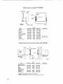
THEORY OF OPERATION
10M.o.
TO
95.3M.o.
RN
10 M.o.
DE T
one that is 1 II OOth of its value.
DE T
TO RN
953 k.o.
the standard. Thus, each resistor is checked against
500 M.o.
250k!)'
(Refer to paragraph
5.4.1. )
453 k.o.
lOOk!).
4.2 DETECTOR.
GUARD
GUARD
The detector circuit consists of a multistage,
dc-feedback amplifier, with an electrometer-tube in
Figure 4-3. The ratio-arm T networks for
the two highest ranges.
put stage, that drives the panel meter.
The over-all
sensitivity of the circuit is about 100 Ilv Imm.
The electrometer tube provides the high input
the voltage on R
N
the voltage on R
p
and R is always 11100th or less of
S
and R
X
. This large "bridge ratio"
results in less sensitivity than would be available if
it were smaller, but has the following advantages:
a.
The standard is 1/100th or less of the unknown
It also has a very
low grid current to avoid appreciable zero shifts when
the bridge output resistance is changed as the range
is changed. Preceding the input tube is a two-stage RC
filter to reduce the effects of pickup. This grid cir
cuit also includes a neon tube, which, with a series
resistor, limits the grid current drawn to less than 1
a much more stable resistor than any unknown
resistor would be. For example, resistors
microampere, whatever voltage is applied.
standards,and resistors to 10 GQ are meas
ured using 1/4% metal-film types.
The voltage applied to the unknown varies by
only 1% over the entire range of R
N
.
(This
would be 10%on a bridge with a 10-to-1 ratio.)
c.
and, thus, decreasing sensitivity.
resistor and, therefore, on many ranges it is
up to 100 MQ are measured using wire-wound
b.
resistance necessary to prevent loading the bridge
Because R
S
is smaller, several effects re
The second stage in the amplifier is also a vac
uum tube because of the high plate resistance of the
first stage. Following the second stage are a common
collector and then a common-emitter transistor stage.
The output voltage is fed back through a divider to the
second grid of the input stage. This grid is also used
for the ZERO adjustments.
The amplifier
panel meter.
output
drives the zero-center
This meter has shaped pole pieces to
give high sensitivity near a bridge null and decreased
sulting from high bridge output impedance,
sensitivity
such as time-constant problems in capaci
balance by eliminating the need for readjustment of
the SEN SITIVITY control during balance.
tance measurement, and capacitance pickup
and zero shift resulting from grid current
on the highest ranges, are reduced.
d .. Because a much lower voltage is applied to
R than to R ' changes in R due to its voltS
X
S
age coefficient are negligible.
This is par
ticularly important when voltage coefficients
up
scale.
This
nonlinearity facilitates
The supply voltage for this detector is very well
regulated. The heater current in the vacuum tubes is
taken from the plate supply and is, thUS, also well
regulated. The critical voltages on the first stage are
further
regulated
by a low-ternperature-coefficient
Zener diode.
are measured with the �R% dial.
The use of the T networks on the highest ranges
can be considered as a further increase of this bridge
ratio.
The bridge is mounted on a subpanel which is
tied to the GUARD point which is the low side of the
detector. Both UNKNOWN terminals are mounted on
a plate connected to this GUARD point to avoid any
leakage resistance across the UNKNOWN terminals.
Leakage resistance from any point on the bridge to
GU ARD
or so.
4.3 TEST-VOLTAGE SUPPLY.
The internal test voltage is regulated by a series
regulator using a 2 mosfet transistors as the series
element. The reference for this regulator is a Zener
diode and the amplifier consists of cascaded transistor
stages. The control circuit is connected to the output
and has a maximum of only 1 0 volts across it while the
remaining output voltage is dropped across a resistor.
causes negligible effect if it is over 200 M Q
The current through this dropping resistor is
This value is easily obtained with good insul
adjusted to be precisely 2 rna by the internal AD} 100
V adjustment and the voltage across the amplifier is
ating materials.
In use, either the GUARD point or the - UN
KNOWN terminal can be tied to the panel ground. In
the latter case, there may be a high voltage between
adjusted to 10 volts with the ADJ 10 V adjustment. The
output voltage is the sum of 10 volts plus 2 rna times
the dropping resistor. This resistor is used to change
the subpanel and t he outside panel.
When the switch on the side of the instrument is
set in the CAL position, the ratio-arm resistor nor
the test voltage. The EX TERNAL AD} terminals shunt
this resistor so that its value may be modified to get
mally used for the range selected is connected instead
This supply is current-limited to about 6 rna for
ranges over 50 volts and to about 14 rna at 50 volts and
lower. Shorting the supply will not damage it.
across the UNKNOWN terminals, and the ratio-arm
resistor normally used two ranges lower is used as
16
intermediate values (refer to paragraph
3.9).
TYPE 1644-A MEGOHM BRIDGE
SECTION
5
SERVICE AND MAINTENANCE
WARNING
These servicing instructions are for use by qualified
personnel only. To avoid electric shock, do not
perform any servicing other than that contained in the
operating instructions unless you are qualified to do
so. Dangerous voltages are present inside this case.
When troubleshooting, a ground strap should be
connected between GUARD and GROUN D on panel to
keep subpanel (Guard) at ground pot.till. Refer all
servicing to qualified service personnel.
5.1 WARRANTY.
The warranty attests the quality of materials and
workmanship in our products. When difficulties do
occur, our service engineers will assist in any way
possible. If the difficulty cannot be eliminated by use of
the following service instructions, please write or tele
phone our Service Department at GenRad, 300 Baker
Ave, Concord, MA 01742gjving full information of the
trouble and of steps taken to remedy it Be sure to
mention the serial and type numbers of the instrument.
5.2 SERVICE.
Before returning an instrument to GenRad for
service, please write to our Service Department, 300
Baker Ave, Concord, MA 01 742, requesting a Returned
Material Tag. Use ofthis tag will ensure proper handling
and identification. For instruments not covered by the
warranty, a purchase order should be forwarded to
avoid unnecessary delay.
5.3 REMOVAL FROM CABINET.
To remove the instrument from the cabinet,
remove the four screws near the panel on the sides
of the instrument and pull the instrument up out of the
cabinet.
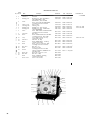
5.4 BRIDGE CALIBRATION.
5.4.1 RATION ARMS.
The r atio arms (and the R -arm resistor) may
p
be checked easily without external standards or test
equipment. Resistance between the UNKNOWN termi
nals will not interfere with the calibration, but imped
ance between the - UNKNOWN and GUARD terminals
will cause calibration error. The eight lower-valued
arms should maintain their values accur atel y for many
years, but the three highest-valued units are less stable.
They can be adjusted to value as follows:
a.
b.
c.
d.
e.
f.
Set the function switch to DISCHARGE. Adjust the
sensiti'vity control.
Set the VOLTAGE ON UNKNOWN switch to
10 v.
C onnect the captive link between the GUARD
terminal and the panel ground terminal.
Rotate the measure-calibrate screw -driver
control on the right-hand side of the instru
ment (see Figure 5-1) fully clockwise.
Set the RESISTANCE MULTIPLIER switch to
100 kG.
Set the function switch to CHARGE-ZERO
and zero the bridge with the COARSE ZERO
and FINE ZERO controls.
17
SERVICE AND MAINTENA NCE
r---- TABLE 5- 1
-
---,
RATIO·ARM RESISTORS -1 GQ
100 kQ
1 MQ
10 MQ
100 MQ
R esistor Used as Standard
RI05 (10 Q)
RI06 (100 Q)
R l 07 (1 KQ)
Rl08 (10 kQ) RI09 (100 kQ)
Resistor Used as Unknown
Rl07 (1 kQ) RI08 (10 kQ)
RI09 (100 kQ)
RllO (1 MQ)
RESISTANCE MULTIPLIER
Setting
g.
Set the function switch to MEASURE and baJ
ance the bridge. It should balance near a
reading of 1. Make note if the balance point
differs from 1 by more than 1/2% (1/4 dial
,..
division.
h. Setothe RESISTANCE MULTIPLIER switch to
eac
ange up to 1 GQ, in turn. For each
range, rezero the meter and then balance
the bridge. Note any ranges that do not bal
ance within 1/2a;oo
i. If any mea�urements are off, the resistor in
error can be identified by the chart of Table
5-1. Note that the 10-Q, 100-Q, I-MQ, and
10-MQ resistors appear only once in this
table. An error in any one of these would
cause only! one inaccurate balance. Values
in between would cause two inaccurate bal
ances that would be off in opposite directions.
If all the values are off in the same direction,
R is in error.
p
j. Set the RESISTANCE MULTIPLIER switch to
10 GQ and set the main R dial to 1. Balance
the bridge by means of the adjustmt::nl on the
side of the instrument in the left-hand hole
(see Figure 5-1).
k. Repeat step i. for the 100-GQ and l-TQ rang
es, making the balance with the middle and
right-hand adjustments, respectively (see
Figure 5-1).
�;
�
MEASURE CALI BRATE
'�'OO� �
IT
Figure 5·1. Calibration controls
for the three highest ratio arms.
The measure·calibrate switch is
shown in the measure position.
Rotate the switch clockwise
to calibrate.
RIll (10 MQ)
To readjust the main rheostat, use a dc bridge
with an accuracy of ±0.1 %. Remove the Type 1644- A
from its cabinet and swing the detector board out on
its cable. (Unsolder leads to terminals 1 and 2 on the
board and remove the screws at the corners of the
board.) Disconnect one of the internal leads that is
connected to the rheostat and connect the dc bridge
across the rheostat.
The main rheostat has a mechanism that permits
accurate adjustment at eight points with adjustment
screws. Table 5-2 lists the dial readings and resist
ance values for these eight points and for intermediate
points that should also be within ±1/2% or 2-1/2 ohms,
whichever is larger. These adjustments are numbered
clockwise starting at the slot in the cam plate. After
any adjustments are made, rotate the dial over its
entire range and recheck all points.
r------
TABLE 5-2
-------,
MAIN DIAL CA LlBRATION
Dial Readin{?
------
0.9
1.0
1.3
1. 5
1.9
2.5
3.2
4.0
5.0
6.3
8.0
10.0
13.0
20.0
32.0
100.0
200.0
00
Resistance
5556
5000
3846
3333
2632
2000
1563
1250
1000
793.7
625.0
500.0
384.6
250.0
156.3
50.0
25.0
0.0
Q
Q
Q
Q
Q
Q
Q
Q
Q
Q
Q
Q
Q
Q
Q
Q
n
n
Screw Adiustment
1
2
3
4
5
6
7
8
5.4.2 MAIN DIAL.
To check the accuracy of the main dial, set the
MEASURE-CALIBRATE switch to measure, connect a
decade resistance box to the UNKNOWN terminals
and measure at various points over the dial range. A
Type GenRad 1 433-Q Decade Resistor (1 MO in 1 00-0
steps) that permits readings up to 1 000 (1 k) on the 1 kO range is recommended.
The main dial should give readings to approxi
mately 1/2% over the range from 0.9 to 10 and to an
equivalent scale distance (approximately 1/2 mm)
over the rest of the range. If the readings differ by
substantially more than this, the main rheostat should
be readjusted.
18
5.5 TEST-VOLTAGE ADJUSTMENTS.
To check the test voltages connect an accurate,
high-impedance voltmeter between the UNKNOWN
terrrhnal s and set the function switch to CHARGE
GUARD
Connect the link between the
ZERO.
terminal and the chassis ground terminal to keep the
'
negative terminal of the voltmeter near ground poten
tial. The test voltages should be within ±3%- They
will vary 1 % over the range of the R dial so that, if
they are readjusted, the R dial should be set to 2 to
obtain center values.
TYPE 1644-A MEGOHM BRIDGE
Q1
WARNING
HEAT SINKS OPERATES
ABOVE GROUND POTENTIAL
Q2
., ..
5-1 A Top View.
The test voltages may be readjusted by means of the
internal adjustments R509 and R513 (located on the
1644-2712 board) (see Figure 5-2). R509 should be set
to give 10 volts and R513 to give 100 volts (with the
corresponding settings of the V OL T AGE ON UN
I<JNOWN switch). If these voltages are correct, but
others are in error, the fault is with one of the dropping
resistoors, R517 through R527. If the voltages are way
off, check the circuit voltages against those of Tables 53 and 5-4 to help determine the faulty component.
TABLE 5 3
DETECTOR VOLTAGES
-
Connect the captive link between the ground and GUARD terminals.
Adjust R231 for 35.0 volts dc between TPI and ground.
Tube or
Transistor
Pin
(Type)
V201
(CK5886)
The voltages in Tables 5- 3 and 5-4 are meas
ured u'nder the following conditions:
V202
(CK6418)
Function sw i tch set to CHARGE-ZERO
RESISTANCE MULTIPLIER switch set to 1 k
Measure-calibrate switch set to measure
VOLTAGE ON UNKNOWN switch set to 10 v
0201
(2N1377)
Volts
to Ground
DC
1
2
3
4
7
1
2
3
4
5
10.8
6.65
3.20
2.0
0.0
26.0
25.7
13.1
10.8
11.8
C
17.9
25.5
'),5.7
B
E
Tube or
Transistor
Pin
(Type)
0202
(2N910)
C
32.5
26.0
25.5
0203
(2N910)
C
27.5
18.0
17.5
0204
(2N1304)
C
45.7
27.5
27.4
0205
(2N1131)
C
35.0
45.7
46.5
Power-line voltage of 1 15 volts.
5.5.1 CURRENT LIMIT ADJUSTMENTS
WARNING
The heat sinks on the 1644-4730 board operates
above ground potential. U.. an insulated tool if
adjustment of R7 is required.
Set the function. switch to discharge. Connect a
milliampmeter between the unknown terminals.
Set the initial conditions:
Voltage on unknown switch set to 10 V
Resistance\mult!plier switch to 1 K
R dial fully ccw 00
function switch set to charge-zero
Measure current according to Table 5-4.
Test
Voltage
DC Volts
to Ground
B
E
B
E
B
E
B
E
TABLE 5-4
Current
10.V
14.0 MA (Adjust R7 if necessary)
20.V
14.0 ±.S MA
SO.V
14.0 ±.S MA
100.V
6.0 ±.5 MA
200.V
6.0 ±.5 MA
500.V
6.0 ±.5 MA
1000.V
6.0 ±.5 MA
19
SERVICE AND MAINTENANCE
&.7 TROUBLE SHOOTING.
5.6.2 DETECTOR SUPPLY VOLTAGE.
The detector supply voltage from TP1 to AT12
should be 35 volts. This is set using R231 (see Figure 5-2).
TABLE 5-5
POWER SUPPLY VOLTAGES
Connect the captive link between the ground
and - UNKNOWN terminals. Adjust R509 for
10.0 volts dc across the UNKNOWN terminals.
(Board 1644-4730)
Transistor (Type)
?JTPIN100)
5.7.1 NOISY OR ERRATIC BALANCE.
If the bridge has not been used in some time,
surface contamination in the wire-wound R or AR%
adjustment may cause erratic behavior of the null indicator. To remedy this situation, rotate these controls over their ranges several times.
5.7.2 LOW BRIDGE SENSITIVITY.
DC Volts to Ground
G
89.0
o
185.0
S
90.0
G
2.9
90.0
0
?JTPIN100)
0
S
0
(2~3440)
C
B
E
2.9
0
-.16
04
(SN3440)
C
B
E
46.0
.4
-.16
0501
(2N910)
C
B
E
6.6
2.7
2.1
Q502
(2N1131)
C
B
E
2.7
4.7
5.5
To check the bridge sensitivity proceed as follows:
a. Set the VOLTAGE ON UNKNOWN switch to
10 v, the measure-calibrate switch (on the
side panel) to calibrate (fully clockwise), the
SENSITIVITY control fully clockwise, and
the RESISTANGE MULTIPLIER to 100 kQ.
b. Balance the bridge. It should balance near 1.
A 1% change in the AR% dial is 1 millivolt and
shouJd give a 2-1/2-division deflection. If the gain is
insufficient, check the voltage in the detector board
and compare them with those of Table 5-3. This should
help locate a faulty component.
DETECTOR BOARD
(SEE FIGURE 5-3)
Figure 5-2. Interior view of the Type 1644-A
20
TYPE 1644-A MEGOHM BRIDGE
5.7.3 INABILITY TO BALANCE OR LARGE ERROR
If the bridge does not balance, several things
e.
If the switch is to be removed, remove the
dress nU[ exposed after step d.
should be considered before the bridge is returned
5.8.2 REPLACEMENT.
for service:
a.
Make sure that the measure-calibrate switch
(side panel) is in the measure position (coun
terclockwise), see Figure 5-1.
The bridge
Install the switches by reversing the removal
procedure and performing the following steps:
will always balance near 1 when this switch
is in the calibrate position.
b.
Make sure that the component is correctly
connected.
c.
Check all panel switch settings.
d.
Try measuring a known resistor.
e.
a.
Make sure the control shafts are turned full
b.
Install the dress nut, if applicable.
c.
Install the bus hing on the shaft; tighten the
ccw.
setscrew.
Refer to paragraph 3.11 for measurement of
high-valued resistors and to paragraph 3.12
for measurements under adverse conditions.
NOTE
Make sure that the end of the shaft does not pro
trude through the bushing, or the knob
6.8 SWITCH REMOVAL-REPLACEMENT.
5.8.1 REMOVAL.
d.
To remove the knobs:
a.
Set the controls full ccw (any position for R
b.
Hold the instrument securely and pull the
won't
seat properly.
Install the knob on the bushing, making sure
the retention spring is opposite the setscrew.
NOTE
knob).
knob off with the fingers.
If the retention spring in the knob comes loose,
reinstall it in the interior notch with the thin
flange set into the small slit in the wall of the
CAUTION
knob
Do not use a screwdriver or other instrument to pry off
the knob if it is tight, since this might mar or crack the
dial.
Do not lose the retention spring in the knob when
Do not attempt to further remove
any part of the large R control, since this control
must be calibrated at a GR service center when the
control is reinstalled.
the knob is removed.
c.
Remove the setscrew from the bushing; use
a hex-socket key wrench.
d.
Remove the bushing.
NOTE
6.9 ELAPSED- TIME INDICATOR.
An elapsed- time indicator is furnished to show the
'
actual total elapsed hours that the instrument has been
operated It is mounted inside the case adjacent to
S103, the MEASURE CALIBRATE Switch (Figure 5-2)
and indicates up to 5000 hours elapsed time. It is a glass
capillary tube marked with 10 graduations that read 0
through 5 000. Elapsed time is indicated by the height of
an electrolytic column in the tube.
The indicator is non-reversible and should be
'replaced when it gets to full scale reading. It is mounted in a
If the knob and bushing are combined when the
polarized fuse clip for easy replacement. Polarity is indi
knob is removed, turn a machine tap a turn or
cated by the size of the electrode at each end.
two into the bushing on the dial for sufficient
grip for easy separation of the knob.
WARNING
The elapsed time indicator contains a corrosive liquid. When
replacing the indicator element use caution and proper tools.
Do not use a screwdriver to pry off the indicator. The glass
tube may f,acture causing contamination of the instrument
or minor injury. A cartridge fuse- puller is a suitable tool for
axtraction of tha alamant .
21
MECHANICAL PARTS LIST
Figure
Qty.
Ref. No.
Name
Description
GR Part No.
FMC
Mfg. Part No.
6
1
Insulator
4
2
Insulator
Binding post
0938-7120
24655
0938-7120
Binding post, J501, EXTERNA L;
0938-3003
24655
0938-3003
5500-5321
24655
5500-5321
Federal Stock No.
J502, EXTERNAL; J503,
3
EXTERNAL; JI01, GUARD
Knob
Knob, VOLTAGE ON UNKNOWN,
including retainer 5220-5402
1
4
Meter cover
1
Meter cover
5
Shorting link
1
Shorting link
6
Binding post
2
7
Binding post, JI02, Ground
Binding post
2
8
Binding post, JI03, -UNKNOWN;
JI04, +UNKNOWN
Knob
Knob, FINE ZERO; COARSE ZERO ,
including retainer 5220-5402
1
9
Dial asm.
1
Dial asm.
10
Knob
Knob, RESISTANCE MULTIPLIER,
11
Stop
including retainer, 5220-5401
Stop, rubber bumper to stop
instrument rotation
2
12
Indicator
Indicator, R; .6.R%
1
13
Knob
2
Knob, SENSITIVITY, including
retainer 5220-5402
14
Knob
Knob, verrier for R Dial; .6.R%,
15
Dial asm.
Dial asm., R
16
Knob
Knob for R dial,
17
Switch
including retainer 5220-5401
including retainer 5220-5401
SWitch, pushbutton, DEPRESS TO
USE .6.R, S104
1
18
Dress nut
1
Dress nut, 15/32-32, 7/16
19
Dial asm.
Dial asm., .6.R%
1
20
Knob
Knob, CHARGE, including
retainer 5220-5401
1
22
Power cord
Power cord, PL501
5720-3713
24655
5720-3713
5080-4800
24655
5080-480�1
5940-927-7452
0938-3022
24655
0938-3022
5940-130-8081
0938-4258
24655
0938-4258
5520-5221
24655
5520-5221
1644-1040
24655
1644-1040
5500-5420
24655
5500-5420
5260-0700
24655
5260-070C
5460-1303
24655
5460-1303
5520-5321
24655
5520-5321
5520-5420
24655
5520-5420
1644-1510
24655
1644-1510
5520-5520
24655
5520-5520
7870-1514
81073
7 -26 (gray)
5800-0800
1644-1500
5500-5421
4200-1903
5340-738-6329
TYPE 1644-A MEGOHM BRIDGE
r:
o
A
fI
Figure 5-3. Etched-board layout for detector circuit
23
ELECTRICAL PARTS LIST
DET ECT O R
CIRCUIT
DE SC 101.1 PTIO N
REFDES
PART
C
201
C
20Z
CAP MICA 410P F 10PCT 500V
CAP MYLAR .001UF 10 PCT 200V
C
203
CAP
CER DISC IJOPF
8 0120peT 500V
NO.
1644- 2100
FMC
PAR T
M FGIoI.
4100- 0600
48 60-1309
81349
56289
CM05F041l I<.N
4404-1109
72982
0831 08215 UOO l Oll
410P .001 UF
4403-3500
S6289
08 45024Z5U05C32
12982
0315
15V
4450-6113
562 8 9
43D300G07S
Uf 15V
OISC.0411.05 U F8 0/20
CAP
CER
TUB
C
206
CAP
ALUM 30 UF
C
201
CAP
ALUM 30
C
208
209
CAP AL UM 30 UF
100PF
10PCT
000
R3AO
4450- 6113
56289
15V
4450 -6113
56289
lt3D 300G075
43D300 G075
CAP ALUM 30 U F 15V
4450- 6113
56289
43D300G07S
6083-1026
6083-1016
03877
14433
I N967B
9V
IN935
IN9678
.SPCT .35W
18V
5PCT
.4W
203
DIODE R ECTIFIER
608 1 - 100 1
14433
IN4003
CR
204
DIODE
INtcH 90PIV lR
125UA GE
6082-1008
14433
IN191
CR 205
DIODE
I N191 90PIV IR
125UA GE
6082-1008
14433
IN 191
2N1371
I N4003
Q
201
T RA N SISTOR 2N1311
Q
202
T RA N SIS T OR ZN910
8210-1311
8 21D-1037
0129 5
04713
Q
203
TRA N SIS T a R 2 N9l0
8 2 10 - 1031
04113
2N 9 10
Q
204
TRANSISTOR 2N1304
8210-1304
01295
2 N1304
Q
205
TRANSIS T OR 2 Nl131
8 210-1025
04113
2N1 l31
R
201
202
RESISTO R
1644-0420
24655
1644-0420
RESISTO R
1644-0420
24655
1644-042 0
R
203
RES
\IIW
6160-1205
75042
BWH
R
Z04
RES
COMP
6100- 610S
81349
RCR2 OGl 06 J
MOLDED 200
11l M
OHM
5
PCT
2W
'jPCT 1/2W
2N91 0
200 0 HM 5PC T
R
205
RES CaMP 150
1/2W
6100-4155
81349
RCR 20G 154J
R
�
206
201
RES CaMP
22 I<.
RES CaMP 2.2 M
SPC T 112W
SPCT 1/2W
6100-32l5
6100-5225
81349
B1349
RCR20G223 J
RCR20G225J
5 PC T 1/2 w
R CR 20G 415J
S PCT
K
6100-5475
81349
5PC T 1 /2 W
6100-1155
81349
RCR20G151 J
SP CT
6100-1395
81349
RCR2OG391 J
�w TRM
51<. OHM 10 PCT 20T
CaMP 120 OHM
5PC T 112W
6051 -250'1
6100-1125
80294
3005P-1-502
RC�20G121 J
R
2 08
RES
R
209
RE S COMP
R
210
RES
COMP 3 9 0 OHM
R
R
211
214
PO T
RES
CaM P 4.1
M
150 OHM
1/2W
R
215
RES
COMP 110
OHM
5PCT 1/2W
6100-111 'j
81349
8134<;
R
216
RES
COMP 6.2 K
OHM
5PCT 1/2W
6100-2625
81349
R CR20 G622J
R
217
RES
COMP 210 O HM
5PC T 1/2 ..
6100-12 75
813 49
RCR2 OG211 J
R
R
21 8
219
RES
RES
COMP 100 K
5 PCT 1/2W
CaMP 470 QH M
5PC T llZW
6100-4105
6100-1475
81349
RCR 20G 104J
81349
RCR20G471J
R
R
220
221
RES
RES
CaMP 150
CaMP
10
6100- 1755
6100-3105
81349
81349
RCR20G 151 J
RCR20GI03J
R
222
RE S
CaMP
R
R
224
225
RES CaMP 300
RES CaMP
20
R
R
226
227
K
OHM
5PCT
5PCT 1/2W
1. 0 I<.
5PC T 112 W
1/2W
81349
RCR2 OGl 02 J
6100- 1305
6100-3205
81349
81349
RCR20G301 J
RES CaMP 8 20 OHM
5PCT 1/2W
RES COMP
41 I<.
5PCT 1/2W
61 0D-1 82 5
6100-3415
81349
RCR20G821 J
81349
RCR20G413J
SP CT 1/2W
S PCT 1/2�
R
228
RES
C OMP 4.7 I<.
5PCT
1/2W
610D-2415
R
229
R ES
CaMP 410 I<.
5PCT
1/2W
6100-4475
R
R
230
231
RES
PO T
COMP
20
WW TRM
R
R
232
233
RES
RES
COMP
COMP
R
R
234
235
RES
RES
COMP 4.1 I<.
COMP 4.1 I<.
V
201
2 02
TUBE VA CUUM
TUSE VACUUM CI<.641 8
203
GE
V
V
RCR20G l11J
6 100-2105
OHM
K OHM
K
51<.
20 I<.
22 I<.
NEON LAMP
81349
813 49
RCR20G203J
RCR20 G472J
RCR20G474J
RCR 20G 203J
3005 P-1-502
OHM
SPCT 1/2W
OH M 10 PC T 20 T
6100-320S
81349
6051-2509
80294
O HM
SPCT 1/2W
5PCT 1/2W
610D-3205
6100-3225
81349
RCR20G203J
81349
RCR20G223J
81349
81349
RCR20G472 J
R CR 20G412J
24655
49956
24 455
838D-S 8 87
CI<.6418
NE-2 'Al A)
SPCT 1/2W
5 PC T 1 /2 W
6100-2475
6100-2415
8 3 8 D-5 8 81
8 3B O - 6418
NE 2
8390-0200
101 K
IN935
CR
R
10PCT
44 00-4600
CAP CER
205
ZENER
ZENER
NUMBER
100V
204
CR 201
CR 202
PIN
500V NM
C
C
C
PC BO ARD
ELECTRICAL PARTS LIST
CHASSIS MCUNTED PARTS
R E FOES
:>N
F
F
501
502
J
J
J
J
J
101
102
103
104
501
502
503
M
201
P
P
DE SC RIP T I UN
FUSE
FUSE
SLO-BLOW 2/10A
SLO-BLOW 2110A
PART
NO.
FMC
MFGR
PART
NUM BER
5330-0600
5330-0600
75915
75915
313 .200
313 .200
0938-3003
0938-3022
0938-4258
0938-4258
0938-3003
0938- 3003
0938-3003
24655
24655
24655
24655
24655
24655
24655
0938- 3003
0938-3022
0938-4258
0938-4258
0938-3003
0938- 3 003
0938- 3003
METER
5730- 1090
24655
5130-1090
501
502
SOCKET AND LAMP ASM
SOCK ET AND LAMP ASM
7510-1360
7510-1380
24655
24655
1510-1360
1510-1380
Pl
501
COHO
120V US 5.5FTHAMMER
4200-1903
24655
42'1 0 -1903
R
R
101
103
105
106
101
108
109
110
111
112
113
114
115
116
111
118
119
120
121
122
212
213
223
511
518
519
520
521
522
523
524
525
POTENTIOMETER
POTENTI OME TE R
RES GH 9.92 OHM .25 pcr 1101
RES FlM 1000HM 1/1~Pcr 50PPMl/2W
RI::S FLM
1 K
l/LOPCT 50PPML12W
RES FlM
10 K
1/LOP CT 50P.PM 112101
RES FLM LOO K
1110Pcr 50PPMl/2W
RES FLM 1M
1/4 PCT 50PPI" 1/2101
RES FLM
10M
1/4PCT 50PPM
2101
RES FLM 95.3M 2 PCT 1/2W
por COMP SCDR 10M OHM 20PCT LIN
RES FlM 95.3M 2 pcr 1/2W
RES fLM
10 M
IPCT 100PPM
1/4101
RES FLM 953K
1 PCT
1/8101
POT COMP SCDR 250KOHM 10Pcr LIN
RES fILM CARBON 500M OHM 2 PCT
RES FLM
10 M 1PCT 100PPM
1/4101
RES f L M 415 K
1 PC T
1/8101
POT COMP SCDR 100KOHM 10Pcr LIN
RES FLM 1l0K
l PCT 1/2101
paTE N TI OME TE R
POT E NTI OMETER
10K OHM 10PCT LOG
POT CaMP KNOB
1 PC T 2101
RES FLM 249K
RES fLM 150K
1 PCT 1\01
RES FlM 49.9K 1 pcr 1/2101
RES FlM 24.9K
1 pcr 114\01
RES fLM 15K
1 PCT
118101
RES fLM 4.99K
1 PCT
1/8101
RES WW MOLDED 6.8 OHM
5 pcr 2101
RES WW MOLOED 6.8 OHM
5 PCT 2W
RES WW AX LEAD
10K OHM 5 PCT 5W
U 433-4120
24655
0915-4060
6983-1000
6188-0100
b 188-1100
6188-2100
6188-3100
61'13-4100
6195-5100
6619-3408
6010-2800
6619-3408
b188-5100
6250- 3953
6010-2000
67'.0-1500
6188-5100
6250-3415
6010-1700
24b55
24655
81349
81349
81349
81349
81349
81349
24655
01121
24655
24655
81349
01121
63060
24655
81349
01121
81349
24655
24655
01121
81349
81349
81349
81349
81349
81349
15042
15042
75042
0433- 4120
0915-4060
6983-1000
RN70C1000B
RN70Cl 001 B
RN 10C 1 002B
RN1DCI003B
RN70CI004C
RN80C 1005C
6619-)408
JA1G032S106Ml
6619- 3408
6188'-5100
RN55D9533F
JAIG032S254Ul
RX-1
6188-5100
RN55D4153F
JA1G032 51 04Ul
RN65D 1103F
0911-3913
0911-3913
J A IN 056S 103Al
RN80D2493 F
RN 15D1503F
RN65D4992F
RN60D2 492 F
RN 55D1502F
RN55D4991F
BWH 6.8 OHM 5 PCT
BWH 6.8 OHM 5PC T
A$-5 10K 5PCT
101
102
:103
1104
501
SWITCH
SWITCH
SWITCH
SWITCH
SWITCH
1870-1514
7890-3300
24655
24655
24655
81013
24655
1890- 3210
7890-3280
1890- 3290
1-26B
7890-3300
501
TRANSFORMER POWER
0345-4004
24655
0345-4004
J
J
R
R
R
R
R
R
R
R
R
R
R
R
R
R
R
R
R
R
R
R
R
R
R
R
R
R
R
R
R
R
S
S
S
S
S
T
R
R
531
538
250V
250V
BI NO I NG POST ASM
BIND I NG PO S T A SM
BINDING
BINDING
BINDING
BINDING
aINDING
3WR
POST
POST
POST ASM
POST ASM
POST ASM
LOA
ROTARY ASM
ROTARY ASM
ROTARY ASM
PUSHBUTTON SPOT
ROTARY ASM
64~0-3110
0911-3913
J971-3913
6020-0400
6590-3249
6550-3150
6450-2499
6350-2249
6250-2150
6250-1499
6160-9685
6760-9685
b660-3105
7890-3210
1890-3280
78~0-3290
ELAPSED TIME INDICATOR
ELAPSED TIME INDICATOR HelDER
1644-0440
1644-0441
RES
REl
6250-4100
6250-4150
FILM 1 M CHM +
FILM 1.5 M O~~
1%
! 1%
T-OC04
T-103
A.T.
I:J
R218
1001(
R208
4.7M
TO
T5OI,8
R233
2ZI(
R226
820
V202
CX641B
L-~~.. ,-----v.~
__ _
R220
750
V201
TIlE-3
I'D
A.r
SIOI ....--~----'W'\,-~P----'Vv'\,---1I>----'+
310R
CR2C4
RZ30
20K
CR205
V203
NE-2
11222
IX
'------+
C209
R225
ZOl(
R~04
RZ21
101(
10M
1'0
./101
AT
?
.;/
A.r
A.r
4
5
WH-RO
Rf;20
~rCOARSE
RZ24
I
300
ZERO
WH-BR
FINE ZERO
A.T
AiLI
/I
BL
R223
10K
~~_w-./U'IM"'-=-".--~:--_......J
170
0
BASE
EMOCOLL
TIW"EO
4
BOTTOM VIEW
0201- (J205
!J
oar
2
:J
I
V202
m
RCD
OaT
., 2
l':J
I
REFERENCE DESIGNATOR ABBREVIATONS
SENSITIVITY
WH-(JN
~
8
8T
C
CA
OS
V201
··
0
R
Diode
S
··
··
•
KL
KS
L
M
MK
Motor
Blttery
= Capacitor
Limp
Fuse
U
Jack
VA
ReilY
AellY Coil
RillY Switch
c
Inductor
• Meter
• Microphone
·
Y
Z
= Plug
= Transistor
•
Resistor
• Switch
T..ndOTmer
InMFat" Circuit
• Diode. Zener
• Sock.t for Plug-In
• Crystal
• Network
··
Reflrences
ASA Y32.16 end Mll-STD-16C
NOTE UNLESS SPECIFIED
I
POSITION Of ROTARY SWITCHES
5 RESISrANCE '" OHMS
I(
1000 OIi'lS'" 'MEGOHM
S ..~W~ COUNllRCLOC.WISE
~ALUES 01'0£ A'IO
2 CONTACT NUMBER'NG Of SWtrCHES ; 6 CAPACITANCE
OVER IN PICOFAR .. OS. LESS
EXPLAINED ON SEPARATE SHEET
SUPPLIED IN ItlSTRlICTlON BOO~
I~ INSTR\JC
TIO" BOOK FOR VOL TAGE~
APPEARI'IG ON DIAGRAM
1 REfER TO SERVICE NOTES
4 RESISTORS 1,2 WA TT
THAN ONE IN .,reROF 4R .. OS
7
8
0
0
~NOB CO"'TROL
9
4T
A'IC><OIl
10 TP
SCREWORIV(R CO"llIlOL
TER""~Al
25
l.ST PO'''T
Figure 5·4. Schematic diagrom af detector circuit.
INSERT DIODE IN
REVERSED DIRECTIC
Figure 5-5. Etched-board layout for power supply
ELECTRICAL PARTS LIST
POWER SUPPlY.CIRCUIT PC BOARO
REFDES
C
C
C
501
502
503
504
505
506
507
508
C
50';
CR
CR
CR
CR
CR
CR
CR
CR
CR
501
502
503
504
505
506
507
508
509
C
C
C
C
C
CR '510
DESCRIPTION
CAP
CAP
CAP
CAP
CAP
CAP
CAP
CAP
ALUM 25 UF lOOV
ALUM 10 UF 250V
ALUM 10UF 475V
ALUM lOUF 415V
ALUM 10 Uf 250V
ALUM 10UF 475V
ALUM 10UF 475V
CER OISC 4700PF 10PCl 500V
CAP CER CISC lOOfF ~OOV
DIODE R ECTIf IER lN4003
ZENER lMl-47A
47V
5PCT 1.5W
RECT IN4005 60OP[V .75A SI A50A
RECf IN4005 600PIV .15A SI A50A
RECl IN4005 600PIV .15A SI A50A
RECl IN4005 6.0OPIV .15A SI A50A
RECT IN4005 600PIV .15A SI A50A
RECT IN4005 600PIV .75A SI A50A
ZENER 1N 148A
3.9V
5PC T .4W
ZE"NER
3~9~
nnsz·
Q
Q
501
502
TRANSISTOR 2N910
TRANSISTGR 21'.11131
R
501
502
503
504
505
506
501
508
509
510
R
R
512
513
514
515
516
RES
RES
RES
RES
RES
RES
RES
RES
POT
RES
RES
RES
POT
RES
RES
RES
V
501
TUBE VACUUM 7239
R
R
R
R
R
R
R
R
R
R
R
R
R
511
COMP
COMP
COMP
CaMP
COMP
COMP
COMP
COMP
COMP
COMP
COMP
COMP
COMP
COMP
COMP
COMP
4.1 K
5PCT 1/ZW
470 K 5PCT l/2W
410 K
5PCT 1/2W
410 K 5peT lIZW
410 K 5PCT 1/2w
1.0 M 5PCT 112W
2.0 K OHM
5PCT 1/ 2W
3.9 K
5PCT 1/2W
SCOR 2.5KOHM 10PCT LIN
10 K 5PCT 1I2W
9.1 K OHM
5PCT 1/2W
11 K OrlM
5PCT 1/2W
SCOR 100KOHM 10PCl LIN
20KOHM
5PCfl/ZW
47 OHM
5PCT 1/2W
62 OHM
5PCT l/2W
PART
PIN 1644-2712
NO.
4lt50-5596
4450-2100
Itlt50-6175
4450-6175
44S0-2100
FMC
MFGR
PART
NUMBER
56289
90201
90201
90201
90201
90201
90201
12982
30D256GIOO
TCW lOUF 250V
TCG 10UF 415V
lCG 10Uf 475V
TeW 10lE 250V
TCG 10Uf 415V
TCG 10 OF 415 V
0811081l5FOO't12K
IN4003
LHZ-47. OA 1.5R47B
. IN4005
IN4005
INlt005
1 Nlt005
IN4005
1N4005
IN748A
60S3-10C4
llt433
24444
14433
Ilt-433
14433
14433
14433
Ilt433
14433
14433
8210-1031
8210-1025
04713
Olt713
2N910
6100-2475
6100-4lt75
6100-4475
610(}-4415
6100-4415
61\)0-5105
610(}- 2205
6100-2395
6010-0100
6100-3105
6100-2915
6100-3115
6010-1100
6100-3205
6100-0415
81349
81349
81349
81349
81349
81349
6100-0265
813lt9
RCR20G472J
RCRZOG474J
RCR20G47ltJ
RCR2OG414J
RCR 20GIt 74J
RCRZOG105J
RCR2OG202J
RCR20G392J
JAIG032 SZ 52 UZ
RCR20GI03J
RCR20G912J
RCR20G113J
JA IG032S 104Ul
RCR20G203J
RCR20G410J
RCRZOG301J
8~80-1239
02639
41t~0-6175
lt4S0-6175
4401-21t 76
" .. 0""1103
6081-1001
6083-1025
6081-1003
6081-1003
6081-1003
6081-1003
6081-1003
6u81-1003
6083-1002
813lt9
81349
01121
81349
813lt9
81349
01121
81349
81349
IN752
lN1131
1239
26
CHARGE
OISCHARGE- ZERO MEASURE
RESISTANCE
MULTlPhIER
MEASURE" ICALIBRATE
---0
POWER
OFF
\, /
~
LEGEND F'f'JR $101
$IO~
LEtlEND F'OR
lOll'"
.--.......--'ltIVY. . 5101
••
,.........,:~.:£-_----e1l21'"
R524 109
6.8
2W
5101
LEGEND FOR 5102
WH-IIK
P502
VOLTAGE
APPLIED
RS38
I·':;"JL
+
WH
A.r.
R501
4.?K
C50I
2SJlF
RS3'
T601
1.0MJ\.
12
T~I
DET e.D
TPI
CRS02
IS
S.6~H_8L_""
I.
A.r.
"
C.RSIO
NOTE:
TMJI
WH-RD-GN
FOR 115V CONNEcr
Iro~
a 2 ro4
R512
11K
R514
F501 0.2AMP
F5020.2AMP
FOR
20K
nov CONNECT
2TO~
A.T.
F501 O.IAMP
FS02 O.IAMP
29
408 V
CW
R!i/~
I
8AS£
EMOCOLL
VOLTAGE ON UNKNOWN
sov
100Y
I
200 V
500Y
1000V
LEGEND FOR 5501
I
I
I
I.
?4V
,]1
A.T:
18
-1!!
H
CS02
IOpF
CS04
10pF
550/
•••••
! __
W:_"'"_V_"-4
+
R50S
4?OK
W~
SSOI
CH5<»
C50~
74V
14
Ie
A.r.
-=:.:..._," RD'8K
I
I
I
I
BOTTOM IIIE'.W
Q501-Q502
A
lOOK
IOJIF
R502
4?OK
~-----~----~~-+--+f! ~~~~---~
WH-GN-BL
R!il
I
I
151
'"
WH-Vr-GY
C.l~.
SCHEMATIC DIAGRAM
FOR
1644-A' MEGOHM BRIDGE
27a
.
NOTE UNLESS SPECIFIED
5. RESISTANCE IN OHMS
K • 1000 OHMS M , MEGOHM ,
I. POSITIQN OF ROTARY SWITCHES
SHOW'" COUNltACttX:ICWI$E.
Z. CONTACt NUMBERING OF SWITCHES
EXPI.AlNED ON' SEPARATE SHEET
• SUPPLIED IN 'INSTRUCTION BOOK.
. 3.
~~~e:J&Jf~~lfNtfl.ThSG~SINSTRUC
APPEARING ON DIAGRAM.
4. RESISTORS 1/2 WATT.
6.
~~C~A~olfi1b~ ~AND
7.
8.
9.
THAN ONE IN MICROFARADS.
KNOB CONTROl
@ SCREWDRIVER CONTROl
AT ANCHOR TERMINAL
TP. TEST POINT
0
10.
'()I"
~
SI02
SOl" Sill
Rf059.92
HI06I00
202"
:J02R
HIOTIK
~20:J"
SOSR
20411
ROI/ 10K
lOS"
RI09 lOOK
206"
20",
Hili 10M 2W
JO!iR ....
~
RlI310M
...
:J08,,_
NII4 .953M 2W
"
ew
ew
RlIT
250K tjHI21
IOQ(
f •..JJ~..;t":".17F'-
@
b
@
~-
laR
SI02
. 4.
Of"l-...rL-'
SI02
21ff
~OR
RI20
4T5K
I/SW
RlI6
953K
1/8W
0
~
~ . 4~
~
~
~
~
'Nm
4.
t•I I. " I. •I. I. I.
~
SOIF .JlRFXAVStHF .JfJM'.1tMFMJTF SD.,
~
I
~2F
~
SI02
112R
·rE·SIr
f"2F
b2.
YE
liT
• • • • • • ·"I"t--'
R516
5102
AT:
2T
RI22
/lOX
Ar.
----P
Q{'
RI23
IX
2W
211F
IDS
J'O
]
5101
I/IF4
~ T' •
2O!lF4
•
•
2011R ~
.208F
••
WH
WH
210R
~
p~
9103
Rn ~
-;
NIOI ~
5.95K
- -
.JGIlJR4~
SIOI
~,
TT T
t
J/OII
IO$F
9103
SIOI
T T 4~
SDk
208"
~
~7F
BI(
L
0
P
IIIF
~
20"4
It
IO!SF
202F
AT.
A.r.
a
2rl5I'" ~
5
WH-VT-GN
liD
-
81r
I
-
;J---LT
A.r.
o~
L--
Cw
~
249f(
50K
.J
2
25K
. AT.
1'02
Sl04
I
r IIAft
«r .~~trCI.
SEE 1644-40
A.r.IDT
SUB-CHASSIS
1'01
RD
elDI
IIIP
A.. r.
1116
A.7:IDD
2w
Rp
I
r
0
0
©
.'7102
47'5K
Rx
WH-II'T
A.T:I'04
JIOI
DEPRESS TO USE
~R
J!JOJ J502 J503
-@
JI03
JI02
0
0
JI04
0
+
GUARD
UNKNOWN
R4N£L
rXT GEN
EXT AOJ
----
J(JgR ...
HI/8 500M
• 210"
NII910M IW
....
J07R ...
HIt295.3M2W
CW~ @
."2D9RNIf5 10M IW
-....
~,,~
RIIO 1M
~Z08R
--
LE6ENO FON SI04
27b
t
...
-,
A
•
�
H
NOTE: The number appearing on the foil side. is not the part number.
The dot on the foil at the transistor socket indicates the collector lead.
�
"
=
C"'I
=
.
'.r!
FtI04
1--�-,
...;.I
102
Figure 5·6. Etched·board layout for bridge circuit (PIN 1644.2721).
ELECTRICAL PARTS LIST
PC BUARD
REFOES
OESCRI PT
C
101
CAP
102
1 \) 't
123
RESl STANCE UNIT
RES GR 25K OHM .2 PC T
R
RES WW
l\Jf 1J
�ClOEO
lK
pn�
PC T
O�M
1&41t-2721
PART
ION
�
R
MVL AR
ASH
r�o
•
Ff1C
MFGR
PAR T
100V
4860-szn
562 � 9
410P 1
lW
0510-2001
6983-502-.
2465 5
24655
6760-2109
75042
0510- 200 1
6983-';024
BWH 1 K lOPC T
10
PCT
2W
NU�tlER
UF 1upeT
27c
1644-0730-00/01
6070-0210-00
6070-0211-00
Q1
VIEW A-A
(TYPICAL)
CAUTION HEAT SINKS ARE 1600V ABOVE GROUND
of.
1644-~~~) ~ @II ~jl@
4730-00
., A
o
C)
CRt:
~o-CBiJ-o
<@
<@~
IIN~-: ~
c
~=r:
.
Q4
~
0'1~
• IIP~5
R2
--11 @
~
~
PIN1
o
PINS
,-
P~2 ~)
@
AT27
c;
1
j
1.750
REF.
NOTES:
1. BARE BOARD NO. 1644-0730-00 REV. 02
2. BOARD VIEWED FROM COMPONENT SIDE.
3. CIRCUITRY SHOWN,
REPRESENTS COMPONENT SIDE.
4. CONTACT FINGERS, IF APPLIC~BLE.
;...1
.
.
- - - - - - - - - - - - - -
5.312 REF.
---------------11...
...t1
ARE TO BE FREE OF
SOLDER AND ADHESIVE .
5. SQUARE PAD • DENOTES THE FOLLOWING :
POSITIVE + END OF CAPACITORS
ROTOR OF TRIMMER CAPACITORS
ARM "OF POTENTIOMETERS
COLLECTOR OF TRANSISTORS
CATHODE END OF DIODES
PIN # 1 OF IC S. RELAYS, AND CONNECTORS.
CP
TCl..ERANCES
\JIl.ESS SPECIFIED N£.
EDlE TO tn.E
.OS5
IILE TO tn.E:t .005 1OHlJ4.
EDlE TO EDlE:t .015
IO.£S f'£lI 6R CO CSPC-OOOO-OS
*
REGULATOR BOARD COMPLETE
SHEET 1 OF 1
lOt ASIC.
28
Item number:
Cescrlption:
PARTS LIST
1644-4730
REGULATOR SOARe
Comp. Desig.
I~em Oescription
Item No.
Qty
~---~-------~-~--~----~-----------------~---~------~-~--~----~-~-Supports
RADIATOR
6070-0Z31-00
2
HEAT SINK TO~20
RADIATOR 10220 usee WITH 0210
SCREW PAN 112-~0 G.375 5S
wAHSER LK EXT TCOTr. .11210 SS
NUT .112-40 0.250.HEX 5S
C1-4
CAP 15t .3100 220WF 5~ SOOV
C5
CAP ALL,., 100 UF 25 V
CRl
ZENER 1N752A S.6V 5~ 0.4~
CR2
RECT Ih40G3 200PI~ O.7SA 51
RI-R4,R6
RES CO~P 470 K SPCT 1/2W
RS
RES COMP 120 CHM 5~ 1/2W
R7
POT CERM TRM 10K Cr.M 20PCT 1T
R8
RES COMP 47 R 5PCT 1/2k
Cl,Q2
TRANS FET HV N-CHANNEl
C3,Q4
TRANS 2N3440 NS MY TO-5 S
Regulator Soard .
Pin.Pin6,AT15t.~\,tlfT t.OS9 C x O.lSI 8R
AT16,AT27,AT28
6070-0210-00
6070-0211-00
7044-1103-00
8050-2200-00
5810-4620-00
4404-1225-00
4450-2300-00
6083-1004-00
6081-1001-00
6100-4475-00
6100-1125-00
6049-0109-00
6100-3475-00
8210-1429-00
8210-1098-00
1644-0730-00
5170-1200-00
2
2
4
4
4
4
1
1
1
S
1
1
1
2
2
1
6
RG:.
410K.
RB
R7
10K
47K
C5
JDo,ur
?()V
eR2
IN1-003
TOLERANCES
!
UNLESS SP£CIFIED ARE
ANGLES ±
•
DECIMALS ±
REC;L)LAT0~
bOAKU
!
PIN \
PrN-S"
AT27
PINC/J
NEn ASSY
SCALE
FILED Al
--x..
C
ORAWN
MEF 'ii 137
,
29
I
Compl.t., cabinet assembly (PIN 1559·2001).
COVER ASSEMBLY
SCREW
PLATE
~
SCREW AND
WASHER
Name
Cabinet
Spacer
Pivot Stud
Screw·
Handle Assembly
Cover Assembly
Nut Plate
Screw
Washer
(4) Feet
(1) Foot, stop
16508·15
GR Part No.
Fed
Mfg Code
1644-1001
4170-0700
4170-1000
7098-0160
5360-1013
4170-0402
4170-1350
7080-1000
8040-2400
5250-1902
52bO-0700
24655
24655
24655
24655
24655
24655
24655
24655
96906
24655
24655
Mfg Part No.
Fed Stock No.
1644-1001
4170-0700
4170-1000
7090-0160
5360-1013
4170-0402
4170-1350
7080-1000
5305-974-0373
MS35337-81 5310-058-2951
5250-1902
5260-0700
Complete handle and mounting plate assembly (PIN 1559·2010)
-r
r
~
STUD
MOUNTING PLATE
(NAME PLATE)
MOUNTING PLATE
(INSTRUCTION
PLATE)
16508·16
Name
Mouting Plate··
(Instruction Plate)
Stud
Slide
Handle
Mounting Plate
(Name Plate)
Washer
Slide Washer
GR Part No.
Fed
Mfg Code
Mfg Part No.
7860-5800
4170-1100
4170-1270
5360-1013
24655
24655
24655
24655
7860-5800
4170-1100
4170-1270
5360-1013
7864-8220
8140-0105
4170-7030
24655
24655
24655
7864-8220
8140-0105
4170-7030
Fed Stock No.
*Tighten 1/4-28 screws to 45-55 in. lbs torque.
"Bend tnounting plate to give 1/32 to 1/16 spacing. both sides.
30
IET LABS, INC.
Standards • Decades • Strobes • Sound Level Meters • Bridges
Formerly manufactured by
GenRad
534 Main Street, Westbury, NY 11590
TEL: (516) 334-5959 • (800) 899-8438 • FAX: (516) 334-5988
www.ietlabs.com
IET LABS, INC.
Standards • Decades • Strobes • Sound Level Meters • Bridges
Formerly manufactured by
GenRad
534 Main Street, Westbury, NY 11590
TEL: (516) 334-5959 • (800) 899-8438 • FAX: (516) 334-5988
www.ietlabs.com