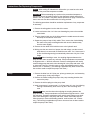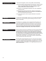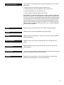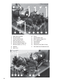
1
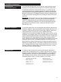
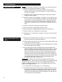
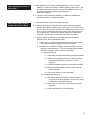
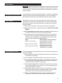
Precrusher/Compactor
Installation, Operation & Service Manual
SP Industries, Inc. • 2982 Jefferson Rd. • Hopkins, MI 49328
Phone: 800-592-5959 • In MI: (269) 793-3232 • Fax: (269) 793-7451)
1
Index
Index ..................................................................................................................... 2
Introduction .......................................................................................................... 3
Tool Requirements for Installation ....................................................................... 3
Power Lockout Procedure .................................................................................... 4
Lifting Precrusher/Compactor Properly ............................................................... 4
Installation Instructions: .......................................................................................... 5-7
Anchoring the Precrusher/Compactor ................................................................. 5
Hydraulic Connections ......................................................................................... 5
Hydraulic Fluid ...................................................................................................... 5
Electrical Connections .......................................................................................... 6
Initial Cycling ........................................................................................................ 6
Container and Precrusher/Compactor Alignment ................................................ 6
Hopper Doors ....................................................................................................... 6
Photo Electric & Infrared Eye Systems ............................................................... 6
Additional Safety Rules ........................................................................................ 6
Remote Control Head .......................................................................................... 7
Funnels, Hoppers, Chutes and Security Chutes ................................................. 7
Dumpers ............................................................................................................... 7
Loading Refuse: ........................................................................................................... 7
Precrusher/Compactor Operation: ....................................................................... 8-10
Compact Mode Operation .................................................................................... 8
Precrush Mode Operation ................................................................................. 8-9
Jogging Machine for Pinning Operation and Manual
Operation of Precrush Gate .......................................................................... 10
Options: ...................................................................................................................... 11
Immersion Oil Heater ......................................................................................... 11
Advance Warning Light ...................................................................................... 11
Hydraulic Cart & Container Dumper .................................................................. 11
Low Oil Warning System .................................................................................... 11
Photo Electric Start & Infrared Start System ..................................................... 11
Trouble Shooting: ................................................................................................. 12-14
Motor Fails To Start ........................................................................................... 12
Motor Starts But Ram Fails To Move ........................................................... 12-13
Motor Starts, Ram Operation Normal, Gate Fails To Move .............................. 13
Gate Does Not Come Down During The Precrush Stroke ................................ 14
Gate Does Not Come All The Way Down .......................................................... 14
After The Gate Closes, The Ram Hesitates While Retracting .......................... 14
Maintenance: ......................................................................................................... 15-16
Gate Cylinder Cavity Cleaning ........................................................................... 15
Filter Cleaning .................................................................................................... 15
Initial Maintenance Check .................................................................................. 15
Hydraulic Fluid Changes .................................................................................... 16
Cold Weather Operation .................................................................................... 16
Instruction for Replacing Components: ............................................................ 17-19
Motor .................................................................................................................. 17
Pump .................................................................................................................. 17
Directional Control Valve .................................................................................... 18
Relief Valve ........................................................................................................ 18
Hydraulic Hoses ................................................................................................. 18
Limit Switch ........................................................................................................ 18
Ram Guide Blocks ............................................................................................. 18
Cylinder Piston Seals ......................................................................................... 19
Relays ................................................................................................................ 19
Timers ................................................................................................................ 19
Starters ............................................................................................................... 19
Motor Overloads ................................................................................................ 19
Circuit Board ...................................................................................................... 19
Terminal Strip ..................................................................................................... 19
Switches ............................................................................................................. 19
Photographs .......................................................................................................... 20-22
Power Unit Hydraulic Components .................................................................... 20
Limit Switches .................................................................................................... 21
Main Electrical Panel .......................................................................................... 22
2
Congratulations On Your Precrusher/Compactor Purchase
SP Industries, Inc., has made every reasonable effort to produce a product
that will perform successfully and safely during its expected life span for the
owners and persons operating the equipment. To increase the safety while
operating this unit, all persons should closely follow these few safety tips.
1. As per OSHA standards, install safety rails and guards on walk ways,
decks, and hopper openings.
2. Erect suitable barriers around cart dumpers, conveyors, etc. to keep
personnel clear of hazardous areas during operation.
3. Make sure all access covers are in place before starting the machine.
4. Keep the precrusher/compactor working area clean, uncluttered, free of ice
and snow, and especially free of oil and grease.
5. Locate the remote control head so the operator can clearly see the charging chamber, although the controls should not be mounted where the
operator has access to the charging chamber.
6. Inspect the container binders and make sure they are securely fastened to
the container as well as to the precrusher/compactor.
7. Secure the container door safety chain before attempting to elevate or
transport the container.
8. Securely lock the container to the hoist frame before transporting.
9. DO NOT place or drop solid objects such as steel plate, steel bar, castings, concrete, etc. into the chamber, this type of material will seriously
damage the precrusher/compactor, gate and gate track, and/or container; and will void warranty.
10. DO NOT stand near the precrusher/compactor when the ram is in motion;
material may be ejected from the charging chamber and cause serious
injury.
Tools Required For Installation Of SP Industries, Inc.
Precrusher/Compactors
1. Fork Lift Truck - To unload and position machine.
2. Hilti Type Drill - For drilling holes in concrete to mount concrete anchors
through precrusher/compactor mounting feet.
3. Hand Tools - Various electrical and mechanical tools for connecting
hydraulic hoses and electrical connections.
4. Welder - For welding machine to cement embedded steel anchor pads if
applicable.
5. Cutting Torch - To adjust or alter optional knock down chute if needed.
3
Power Lockout Procedure
The following are the General Industry Safety division’s minimum requirements
for establishment of a Power Lockout Procedure.
A written power lockout procedure shall be provided.
All necessary employees shall be instructed on this procedure. Employees
shall be instructed in and conform to the following procedures:
1. Alert the operator(s) that power is being disconnected.
2. Before starting repair, service or setup work on engine, motor or power
driven equipment, person(s) performing work shall make sure power is
disconnected (and any hazardous residual pressure shall be relieved)
prior to and during such work. A padlock(s) shall be placed at the point of
power disconnect where lockout is required by each person(s) performing work. Individual locks shall be used or an authorized employee of
each crew shall be responsible for placing the lock and determining that
each crew member is clear before removing the lock, or a supervisor
may place a lock for which he has the only key, and assure that all crews
are clear before removing the lock. Keys shall be removed at the time of
lockout. Before work is started, equipment shall be tested to insure
power is off.
3. No one other than person(s) placing padlock(s) on power lockout shall
remove padlock(s) and restore power. (Exception: Supervisor may
remove padlock(s) and restore power after a thorough check to make
sure that no person will be exposed to danger.)
4. If it is necessary to work on a machine or installation to be continued by the
next shift personnel, the padlock(s) of the original employees shall be
removed by those employees in the presence of the oncoming shift who
will immediately insert their own padlock(s) into the disconnect. All
concerned personnel (operators, repairmen, and supervision) shall be
thoroughly informed.
5. A machine connected to an electrical source by a plug-in cord shall be
considered in compliance if the plug is disconnected and tagged, provided that the plug is a legal disconnecting means. (Plugs are acceptable
as disconnecting means only for portable motors and 100V fixed equipment.)
6. Any equipment component that needs blocking to prevent its movement by
gravity or other means must be blocked.
Lifting the Precrusher/Compactor Properly
The precrusher/compactor can be off loaded or moved from the side.
The fork lift must be large enough to handle the weight of the compactor. If the
fork lift will not lift the unit or if the unit teeters when lifted, the compactor must
be lifted with a larger fork lift or two fork lifts on opposite sides. To balance the
compactor when lifting from the side the forks must be positioned off center,
closer to the chamber end, to compensate for the greater weight at this end.
Once the compactor is in its approximate position, its position can be adjusted
without lifting it completely off the concrete. Lift one end of the compactor and
shift it into position with the fork lift.
4
Installation Instructions
Anchoring The
Precrusher/Compactor
If the installation drawing guide lines are followed, enough clearance will be
allowed for servicing internal parts through the rear and side access panels.
The precrusher/compactor must be bolted securely to a concrete slab and
located as illustrated on the installation drawing. SP Industries recommends
using anchorable mounting pads embedded in the concrete if new concrete is
poured or anchors such as Thunderbolt Concrete Anchors if existing concrete
is used. The installation drawing shows the mounting hole pattern and anchor
pad layout.
CAUTION: If the concrete is not level, all four compactor mounting pads will
not be touching the cement. If this is the case, do not pull the legs to the
concrete, the legs which do not touch must be shimmed then fastened securely. If the raised leg is pulled down, the frame could be twisted causing a
gap between the ram and floor surface, resulting in undue jamming and
premature floor wear.
Hydraulic Connections
The hydraulic connections may have loosened during shipment and should be
checked for tightness. When connecting the hoses from the power unit to the
cylinder(s), wrap thread sealant tape around or apply liquid pipe sealant to all
male threads that do not connect to a factory supplied swivel fitting.
Hydraulic lines over and above standard hose length, usually ten feet, must be
hard piped. All hard piping whether it’s the standard length of six feet or above
requires schedule 80 pipe and 2,000 lb. pipe fittings. If the lines are more than
20 feet long, pipe with a larger diameter must be used to prevent pressure
losses. Vibration can be lessened by using hydraulic hose between the cylinder
connection and the pipe line, and between the pipe line and the power unit.
During operation, hydraulic hoses should not rub against an abrasive surface.
When the ram changes direction, the pressure change will cause the hoses to
move. Rubbing could cause leakage, usually starting in the form of a mist and
eventually turning into a steady stream. An explosion could occur if an open
flame came in contact with the leaking oil.
Hydraulic Fluid
The reservoir must be filled with a premium grade hydraulic fluid having a
viscosity index of approximately 100, a viscosity of 150 SUS at 100° F and a
Maximum viscosity of 4000 SUS in cold starting conditions. Thermostatically
controlled immersion oil heaters are recommended for extreme conditions.
Also, the fluid must have antifoam, antiwear and water separating additives.
Acceptable hydraulic fluids for all other conditions are as follows:
Union 76 Anax AW 150
Gulf Harmony 32
Shell Tellus 32
Texaco Rando HD 32
Mobil D.T.E. 13
Standard Industron 44
Exxon Nuto H 32
5
Electrical Connections
CAUTION: The electrical controls must be connected to the correct power
source (230 or 460).
Power to the unit must be provided through a customer furnished fusible
disconnect switch which shall be visible and accessible to the operator of the
unit. Local electrical codes should be consulted for proper installation specifications.
The voltage that the unit is factory wired for is listed on the decal attached to
the main electrical box door.
If the incoming line voltage differs from the power unit factory wired voltage,
the motor connections, transformer connections, motor starter overloads, and
the size of power line wires, if they are not rated for higher line current, must
be changed. The wiring diagram will show the correct wire and overload size.
6
Initial Cycling
Before the unit is coupled to the container, it should be cycled several times,
first in compactor mode, then in precrusher mode. During this cycling, observe
all pipe and hose connections for leakage. If the pump makes loud or crackling
noises and/or the ram jerks, stop the machine and tighten all intake connections to the pump from the tank. After smooth cycling is observed, stop the ram
in the RETRACTED POSITION and check the fluid level on the sight gauge. If
the sight gauge indicates that the reservoir is not full, add an acceptable type
of fluid until the gauge indicates the reservoir is full.
Container and Precrusher/
Compactor Alignment
One inch all around clearance should be observed when the container is
connected to the precrusher/compactor charge opening, the compactor mating
surface of the container should fit flush with the mating surface of the precrusher/compactor. If a gap is present on the top or bottom, the front or rear
legs of the precrusher/compactor and/or the wheels of the container, must be
shimmed until proper alignment is reached. Do not over tighten the container
hooks. The container should only be drawn snug against the precrusher/
compactor.
Hopper Doors
If the precrusher/compactor is equipped with a hopper, security chute or safety
gate which uses a safety interlock switch, the gate or door must be closed to
operate the precrusher/compactor. With the interlock switch in a closed position, power will pass to the control system allowing the machine to operate.
Photo Electric & Infrared Eye
Systems
If the precrusher/compactor is equipped with a photo electric eye or infrared
eye, the reflector or receiver must be properly aligned opposite the eye to
reflect the light beam and the light beam must be free of obstructions.
Additional Safety Rules
To comply with WASTEC (Waste Equipment Technology Association) guidelines for stationary compaction equipment along with current ANSI (American
National Standards Institute) Safety Standards, SP Industries, Inc. has made
every reasonable effort to adhere to this standard in the design of the machinery, controls, and safety devices of its compaction equipment. If SP Industries
Inc. does not install the equipment, it is the responsibility of the owner to
comply to the following safety rules.
Remote Control Head
The remote control head is supplied with a Keyed Off/On Switch, Start Button,
Stop Button with a Container Full Warning Light, and a Compactor/Precrusher
Mode Switch. This remote control head must be permanently mounted within
three feet of the point of operation.
Funnels, Hoppers, Chutes,
Security Chutes
All access doors and/or safety gates on factory built funnels, hoppers, chutes
and security chutes are provided with factory installed interlock switches where
required. If the funnel, hopper, etc. is installed at the job site, it is the responsibility of the installer to provide an interlock system, so that the precrusher/
compactor may only run when all safety gates and access doors are closed.
All factory built equipment is safety marked with applicable safety labels
required by current ANSI Safety Standards. It is the responsibility of the owner
to obtain these labels and apply them to all chutes, hoppers and funnels built
by anyone at the site of the compactor or built elsewhere and brought to the
site for installation.
All funnels, hoppers, chutes and security chutes should be mounted to the
compactor with low hydrogen rod welds; smaller units may be bolted securely
to the precrusher/compactor.
Dumpers
It is the owner’s responsibility to provide suitable safety enclosures and/or
gates for all dumpers. Safety interlock switches enabling the dumper to be
operated only when gates are closed must be mounted on all gates leading to
the dumping area. SP Industries, Inc., can provide safety decals to post on or
near safety enclosures and gates constructed on the job site.
The dumper controls, except on remote units, are mounted in the remote
control box with the precrusher/compactor controls. The controls consist of a
mushroom type Start/Stop Button, similar to the Compactor Start/Stop Button,
but tagged “DUMPER, PULL TO START, PUSH TO STOP” and an Up/Down
Selector Switch. Pushing either the Dumper Start/Stop Button or the Precrusher/Compactor Stop Button will stop the dumper in any position. When the
light is “on” in the Dumper Start/Stop Button, this indicates that the dumper
motor is running
Loading Refuse
1. DO NOT enter the charging chamber.
2. DO NOT throw solid objects such as steel plate, castings, concrete
blocks, etc. into the chamber, this type of material may seriously damage the
precrusher/compactor and/or container.
Note: This Will Void The Warranty.
3. DO NOT operate dumping devices unless area is clear of all personnel.
OSHA and the manufacturer require erection of suitable barriers when these
devices are used.
4. DO NOT stand near the precrusher/compactor when the ram is in motion;
material may be ejected from the charging chamber and cause serious injury.
To avoid falling into the compaction chamber, stay at a safe distance when
loading refuse into the precrusher/compactor. After the refuse has been
loaded into the chamber, stand at a safe distance during operation.
7
Precrusher/Compactor Operation
The precrusher/compactor has three modes of operation. These are precrush,
compact and pinning boost override.
Before operating the precrusher/compactor in any mode, a compaction container must be attached to the charge opening.
The controls, other than the pinning boost override system controls, are
mounted in the main control panel or a remote control head. Pinning boost
override controls are mounted for convenience on the side of the compactor
near the charge opening.
Compact Mode Operation
CAUTION: The Power supply to the controls MUST BE TURNED OFF while
adjustments in the control panel are made.
1. Set 4SS (Precrush/Compact Mode Switch) in the “compact” position.
2. Set 1TR (Thirty Minute Cycle Timer) as desired. The machine can be set
to cycle from one complete cycle to a thirty minute cycling time. Set the
timer for 10-15 seconds less than the time needed for the desired
number of cycles.
3. 1SS (Off/On Selector Switch) should be set in the “on” position.
4. 2SS (Pin/Off/Run Selector Switch) should be set in the “run” position. 2SS
should only be switched when manually jogging the ram back and forth.
Usually it is only used by the container hauler.
5. After steps 1-4 are completed, the electrical disconnect may be switched to
the “on” position.
6. PUSH THE START BUTTON: In this mode, the machine will continue to
run until:
A. 1TR has timed out, stopping the ram in the retracted position.
B. The ram is unable to reach the limit switch because of a full load or an
obstruction. This will be indicated when the full container light comes
on. Before the automatic mode will continue, the Stop Button must
be pushed to reset 2TR.
C. The Stop Button is pushed.
CAUTION: Do not allow personnel unfamiliar with this equipment to make
adjustments and modifications to factory settings.
Precrush Mode Operation
In order for the precrusher/compactor to be used in the precrush mode, the
Pin/Off/Run Switch must be set in the run position, the Keyed Off/On Switch
must be in the “On” position and the Precrush/Compact Mode Switch must be
in the precrush position. The cycle will begin when the Start Button is pushed
and held for approximately one second, then released.
The precrusher will continue to run until 1TR has timed out, the Stop Button is
pushed, the Keyed Off/On Switch is turned off or the container is full.
1. Set 4SS (Precrush/Compact Mode Switch) in the “Precrush” position.
2. Set 1TR (Thirty Minute Cycle Timer) as desired. The machine can be set
to cycle from one complete cycle to a 30 minute cycling time. Set the
timer for 8 seconds less than the time needed for the number of complete precrush cycles desired.
8
Precrush Mode Operation
(Cont.)
3. Set 1CTR (Precrush Counter) to desired number of precrush strokes up to
a maximum of nine.
NOTE: To set the number of precrush cycles that the counter is factory set
for, turn 1TR to its maximum setting to record the time needed for the
number of complete precrush cycles desired, then reset 1TR for 8
seconds less than the recorded time.
4. Set 1SS (Off/On Selector Switch) to the “On” position.
5. Set 2SS (Pin/Off/Run Selector Switch) to the “Run” position.
6. After steps 1 - 5 are completed, the electrical disconnect may be switched
to the “On” position.
7. Push the start button.
The precrusher cycle will run through the following steps:
1. If the precrusher gate is open when the precrush cycle begins, the ram will
move forward into the container to clear any refuse remaining in the
chamber. The gate will close, sealing the charge opening, after the ram
moves past the gate during its return stroke. The first precrush cycle will
start as soon as the ram reaches the retracted position.
2. The ram moves forward crushing the material in the charge chamber
against the gate.
3. If the precrusher counter has been set for more than one precrush cycle,
the ram can no longer move forward and the system has reached its
maximum pressure, the ram will retract completely and step 2. will be
repeated.
4. When the predetermined number of precrush cycles have been completed,
pressure will be released from the ram and the gate will open.
5. Once the gate is open, the ram will resume its forward movement and
compact the material into the container, then begin to retract.
6. After the ram has retracted approximately two feet past the gate, the ram
movement will stop and the gate will close.
7. When the gate is closed, the ram will continue to retract until the charge
chamber is cleared.
As mentioned above, the number of precrush cycles is controlled by counter
1CTR located inside the main control panel. This counter will allow the ram to
precrush the material within the charge chamber from one to nine times before
the gate will open.
In addition, the unit is controlled with an automatic multicycle system which
operates as described above. However, when the unit is in the precrush mode
additional time must be added to the timer to complete more than one cycle,
especially if counter 1CTR is set for more than one precrush cycle. The
operator must review the operation and adjust the counter and timer to best
suite the waste handling system’s needs.
IMPORTANT NOTE: Set 1TR for 8 seconds less than the time needed for
the number of complete cycles desired.
9
Jogging Machine For Pinning
Operation And Manual
Operation Of Precrush Gate
Note: Controls are normally mounted on the left front corner of the precrusher/compactor.
1. Use key to turn 2SS (Pin/Off/Run Selector Switch) to the “Off” position.
Two operations may now be performed:
A. Manually raise or lower the gate.
B. Manually extend or retract the ram.
2. Manually raising or lowering the gate.
A. Turn 2SS to the “Pin” position and hold.
B. While holding 2SS, turn and hold 5SS (Precrusher Gate Up/Down
Switch) in either the “Up” or “Down” position.
3. Manually extending or retracting the ram.
A. Turn 2SS to the “Pin” position and hold.
B. While holding 2SS, turn and hold 3SS (Retract-Run-Extend Selector
Switch) in either the “Retract” or “Extend” position.
Note: To pin a load, the gate must bi in the completely up position.
10
Options
Immersion Oil Heater
The heater is adapted to the one inch NPT half coupling at the end of the tank
under the electrical box and necessitates the use of a larger transformer. The
heater is thermostatically controlled to maintain oil temperature at the desired
setting during cold weather. The heater will maintain the temperature only while
the disconnect supplying power to the electrical box is in the “on” position.
Advance Warning Light
The advance warning light consists of a pressure regulated switch, an additional relay and a warning light which is mounted in the remote control panel.
The purpose of this system is to alert the operator when a pressure less than
the maximum operating pressure is reached. The pressure is factory set at 400
PSI below maximum operating pressure. This will allow the advance warning
light to indicate when the container is approximately 75% full giving the operator time to contact the hauler to change containers for minimal compactor
down time.
Hydraulic Cart & Container
Dumper
A hydraulic dumper consists of a side, deck, or remote mounted dumping
mechanism; and a separate motor, valve, pump and operating controls. A
typical dumper will have its hydraulic components mounted on the same
reservoir as the precrusher/compactor’s hydraulic components and the
operating controls in the same control box as the precrusher/compactor’s
operating controls.
The dumper may be started with or without operating the compactor as long as
2SS is in the “Run” position, 1 SS is in the “On” position and the precrusher/
compactor stop button is in the closed (up) position.
Low Oil Warning System
The low oil warning system consists of a reservoir mounted, low oil sensing
device, relay, and a warning light. The low oil sensing device sends a signal to
the low oil warning light, mounted in the main control panel, when the oil level
is dangerously low. If this occurs, the precrusher/compactor shuts off and the
low oil light comes on. The reservoir hydraulic fluid must be checked and filled
to the proper level as read on the oil sight gauge.
Photo Electric & Infrared Start
System
The photo electric or infrared start system consists of a photo electric or
infrared eye assembly, warning buzzer, flashing strobe light, and a reflector or
receiver. The controls are set for the precrush or compactor mode. The cycle
will start automatically when the material in the compaction chamber builds up
to a point where it blocks the beam of light between the photo electric eye and
the reflector. The precrusher/compactor will continue to cycle until 1TR
reaches its preset cycle time, the container is full or the Stop Button is pushed.
11
Trouble Shooting
Motor Fails To Start
NOTE: When calling SP Industries for information, you must have the serial
number of the precrusher/compactor available.
1. Check that all switches are in their proper positions. The Pin/Off/Run
Selector Switch must be in the “Run” position. The Off/On Switch must
be in the “On” position.
2. If applicable, check to make sure all safety gates or doors are closed to
energize interlock switches.
3. Check the container full warning light. If the light is on, the container may
be full or the ram may be jammed by an object in the charging chamber.
If the container is full, change containers; if the compactor is jammed,
clear the jam, see page 10. Once the problem is resolved, push the
Stop Button to reset the system, then start the compaction or precrush
cycle.
4. Check the 4 amp fuse located in the main control box.
5. Check for proper line voltage entering the control box.
6. Check for proper line voltages going into and out of the transformer.
7. Check for “kicked-out” overloads on the motor starter.
8. Call the factory or an electrician if 1 through 7 check out, but the motor still
fails to start.
Motor Starts But Ram Fails To
Move
1. Check the level of hydraulic fluid in the reservoir. If it is low, add hydraulic
fluid until it reaches the proper operating level.
2. Check the rotation of the motor. The shaft must rotate in the direction of the
arrow decal on the motor housing.
3. Check the motor and pump coupling. The motor coupling must be in contact
with and turning the pump coupling.
4. The ram operating limit switch, located inside the machine between the
hydraulic cylinders in the forward position (See Photo Page 21), must be
both in an operable condition and actuated by the ram. Adjust the limit
switch arm if necessary. If the limit switch is inoperable when the ram
moves forward, the unit will shut off and the red full container light will
illuminate. If the limit switch is inoperable when the ram is retracted, the
ram will stop at the rear position and system pressure will read the same
as container full pressure; however, the full container light will not
illuminate and the motor will not shut off.
CAUTION: The cylinder may be seriously damaged if the limit switch is
improperly adjusted. The limit switch must be actuated 1/2" before the cylinder
reaches the end of its stroke. If the arm is not correctly adjusted and the
cylinder is reaching the end of its stroke, a loud banging noise will be heard
when the ram changes direction.
5. The Timing Relays must be properly set. (See Pages 8-9)
6. The Directional Control Valve may be stuck in neutral position or the valve
solenoid may be defective. To dislodge the control valve, insert a small
rod into the end of the solenoid housing and push in while the motor is
running; the ram should move forward or backward. If the ram does not
move, the spool may be inoperative.
12
Motor Starts But Ram Fails To
Move (Cont.)
7. Check whether or not the pump is building pressure. If not, it may be
defective. To check the pressure, install a pressure gauge in the 1" tee
provided on the pump side of the circuit control module. Take the 1/4"
plug out of the tee for pressure gauge installation.
(See Photo Page 20)
8. If 1 through 7 fail to resolve this problem, a cylinder may be defective.
Contact the factory for further information.
Motor Starts, Ram Operation
Normal, Gate Fails To Move
1. Is the Mode Switch (4SS) in the Precrush position?
2. Check the Ram Retracts Past Gate Limit Switch inside the compactor
between the hydraulic cylinders (See Photo Page 21). If the limit switch
is loose, stuck, or the arm is held forward or backward by trash accumulation; it will not initiate the cycle for the gate to come down during the
ram reverse stroke. This will only allow the machine to function as a
compactor. Tighten, free or replace the limit switch as needed.
3. If the gate is down and the ram moves against the gate on the last
precrush stroke, but the gate doesn’t open.
A. Replace the 1/4" plug in the tee entering the circuit control module
with a pressure gauge if gauge has not been installed.
B. If the pressure is 1800 PSI or higher, the pressure switch may be
sticking or malfunctioning. a. Turn the Compact/Precrush Mode
Switch to “Compact” mode. Push the Start Button.
1.) If the gate goes up:
a.) Check Relay #6 (Ram Extend Relay) for proper operation.
b.) If Relay #6 is operating correctly, the pressure switch
may be malfunctioning. (See Item 2 on Photo
Page 20)
c.) Check for hydraulic obstructions in the pressure switch.
d.) Check the pressure switch’s electrical mechanism for
proper operation.
e.) Contact the factory for more information.
2.) If the gate does not go up:
a.) Check Gate Open Limit Switch for correct operation. It
may be stuck in the up position or the arm may be out
of adjustment. (See Photo Page 21)
b.) Check relay #7 (Gate Open control Relay) for proper
operation.
c.) Contact the factory for more information.
13
Gate Does Not Come Down
During Precrush Stroke
1. Check the Gate Open Limit Switch for correct operation.
2. Check the Ram Retracts Past Gate Limit Switch for proper operation
3. Check relay #7.
4. Contact the factory for more information.
14
Gate Does Not Come All The
Way Down
Often during the first operation of the day or in cold weather, the gate may not
come all the way down. Once the machine has warmed up, it should operate
normally. However, if the gate consistently fails to close all the way timer 2TR
should be adjusted for more time. It should normally take between 6 and 7
seconds for the gate to close completely.
After The Gate Closes, The Ram
Hesitates While Retracting
When the precrusher/compactor is started in the precrush mode after the
system has been completely shut off, the ram will pause during retraction for
approximately eight seconds, then continue to operate normally. This is normal
operation if the system is set for more than one precrush cycle.
Maintenance
CAUTION: Before performing any maintenance on the precrusher/compactor
or power unit, shut off the power at the disconnect switch and lock this switch
in the “off” position. Do not service the machine if it is possible for someone to
start the machine.
Gate Cylinder Cavity Cleaning
The gate cylinder cavity must be checked monthly for material or trash buildup
that may prevent the gate from opening completely. If there is a buildup, the
gate cylinder access covers can be removed to clean the cylinder cavities.
Filter Cleaning
SP Industries Inc. power units use a permanent type oil filter which may be
reused after each cleaning. To keep down time at a minimum while cleaning
the dirty filter, replace it with a spare clean filter. The dirty filter may then be
cleaned as follows:
1. Soak the filter in kerosene or other solvent to loosen the contaminant.
2. Lightly scrub the filter with a soft bristle paint brush. DO NOT USE A WIRE
BRUSH.
3. Remove embedded contaminants with clean, dry shop air. Direct the flow of
air against the inside of the filter with a perforated support.
4. Again, wash the filter in a solvent and blow with shop air, then inspect for
damage. Holes in the filter cloth will leak dirt into the pump and valve
which may cause malfunctions in the hydraulic system. See the chart
below for recommended filter change frequency.
Usage
Heavy: 6 Hrs. Per Day
Medium: 2-6 Hrs. Per Day
Light: Up to 2 Hrs. Per Day
Initial Maintenance Check
Filter Change Or Clean Frequency
Initial change after 2 weeks
Thereafter every 3 months
Initial change after 3 weeks
Thereafter every 6 months
Initial change after 4 weeks
Thereafter every 12 months
The first maintenance check should take place with the first filter change and
include the following:
1. Check and tighten all electrical and hydraulic connections on the power unit,
control head, and cylinders.
2. Check and tighten all mechanical fasteners, nuts, bolts, set screws, etc.
3. Drain some hydraulic fluid from the bottom of the reservoir by removing the
3/4" plug from the half coupling under the oil level gauge. Inspect the
fluid for the presence of water. Drain all water.
4. Check the Nylatron guide blocks, located on the rear of the ram, for looseness and unreasonable wear. Call a factory authorized representative if
wear seems excessive or uneven.
5. Check the gate cylinder cavities for material or trash build up. If material
build-up prevents the gate from opening completely, the gate cylinder
access cover must be removed and the cavity cleaned out.
6. Check the ram hold down bars for wear. If the gap is greater than 5/16"
between the ram top and the hold down bars, contact the factory.
15
Hydraulic Fluid Changes
Under normal conditions the fluid can be used for an indefinite time. If
you suspect that the fluid has been contaminated or has otherwise lost its
usefulness, drain off some of the fluid, take it to an oil distributor and have it
analyzed.
The bottom of the reservoir should be inspected every 12 to 18 months for
sludge deposits. If there is a detectable layer of sludge, the reservoir should be
drained, flushed with kerosene or another suitable solvent, then refilled with
clean hydraulic fluid.
Cold Weather Operation
16
Recommended oil may be used for all but extremely cold temperatures. An
immersion oil heater is recommended for an area where temperatures are
expected to frequently reach 0° F or below.
Instructions For Replacing Components
NOTE: When calling SP Industries for information, you must have the serial
number of the precrusher/compactor available.
CAUTION: Before attempting any repairs on the precrusher/compactor or
power unit, shut off all electrical power at the disconnect switch and lock this
switch in the “off” position. See power lockout procedure on page 4. Make sure
that no one can start the machine while it is being serviced.
The following procedures should be used when replacement of any component
is necessary.
Motor
1. Remove the wiring plate from the side of the motor.
2. Loosen and remove the 4 or 6 wire nuts fastening the power wires and the
motor leads.
3. Take the electrical lock nut off the fitting where the conduit enters the motor,
then drop the conduit out of the hole.
4. Support the pump to keep it fairly stable. Then, remove the 4 bolts holding
the motor to the pump mounting bracket and move the bracket away
from the motor slightly.
5. Remove the four bolts which hold the motor to the hydraulic tank.
6. Making sure the new motor is of proper size and voltage, use the removal
steps above in reverse order to install the new motor. If a C-face motor is
in use, the following warning is automatically taken care of by the C-face
flange.
WARNING: When installing a motor, the coupling alignment between the
pump and the motor must be very accurate. Pump manufacturers recommend
an alignment with +/-.005 inch tolerance. Excessive misalignment will usually
cause leaking pump shaft seals, short bearing life in the pump and motor, and/
or short total pump life. Shim the pump or motor with banding material, small
washers, etc., if necessary. (This warning is applicable only when a nose cone
has not been used to couple the pump to the motor.)
Pump
1. Remove the bolts from all 3 (inlet port, primary pressure port, and secondary
pressure port) 4-bolt pump flanges.
2. Remove the 2 bolts holding the pump to the pump mounting bracket, then
remove the pump.
3. Remove the half-coupling from the pump shaft.
4. Install a new pump in reverse order. If a C-face motor is in use, the following
warning is automatically taken care of by the C-face mounting nose
cone.
WARNING: Care must be taken when aligning the coupling between the
pump and motor. Pump manufacturers recommend an alignment with +/-.005
inch tolerance. Excessive misalignment will usually cause leaking pump shaft
seals, short bearing life in the pump and motor, and/or short total pump life.
Shim the pump or motor with banding material, small washers, etc. if necessary. (This warning is applicable only when a nose cone has not been used to
couple the pump to the motor.)
17
Directional Control Valve
1. Remove the wiring plate, wire nuts, wiring conduit, and conduit fitting.
2. Remove the pressure switch mounted on the valve body. To do this, remove
the two 1/4" bolts that hold the base to the main body of the pressure
switch. Caution must be taken not to drop the plunger out of the
pressure switch when it is loose from its base.
3. Remove the 4 or 6 mounting bolts holding the valve to the manifold block.
Remove the valve.
4. Replace with a new valve in reverse order, making sure all O-rings are
installed and properly placed. If an O-ring is left out or pinched between
the valve and manifold, the fluid will leak.
5. All valve mounting bolts must be torqued as indicated on the hydraulic
schematic.
18
Relief Valve
If a relief valve must be changed in whole or part, the systems relief pressure
must be reset. If the correct factory pressure setting is not known, call the
factory for information.
Hydraulic Hoses
SP Industries Inc. compacting units are equipped with SAE rated hose. All
hoses must be replaced with hoses of the same type. The SAE number is
stamped or impressed on the outer layer of the hose. If there are any questions, call the factory. Make sure that no part of the hose rubs against an
abrasive surface during machine operation. This rubbing could eventually
cause a leak, creating a low oil level in the reservoir and a fire hazard.
Limit Switch
When removing a limit switch, the replacement must have the same sequence
of normally open and closed contacts. If the switch is wired differently, the
electrical system will not perform correctly. When setting the ram operating
limit switch actuator, the switch must be actuated before the cylinder bottoms
out in either direction. A loud banging noise at the end of the stroke will indicate
that the cylinder is bottoming out. This will shorten the life of the cylinder
bushings, seals, and packings. The limit switch should be actuated between
1/4 to 1/2 inch before the end of either stroke.
Ram Guide Blocks
The side guides should be adjusted to make firm contact with the compactor
frame sides. Top guides should be adjusted 1/2 turn clockwise after meeting
the guide rail squarely. Bottom guides should be adjusted with an 1/16" to 1/8"
gap between the block and the guide rail. Over tightening these blocks may
result in excessive wear.
Cylinder Piston Seals
Loss of power in the hydraulic system may be caused by any one or more of
the following:
1. Defective relief valve (broken spring, scored ball, etc.)
2. Defective pump (pump seals, defective vanes or gears, etc.)
3. Defective directional valve (scored spool, etc.)
4. Internal cylinder leakage through the piston seals.
SP Industries Inc. recommends that before making an attempt to replace the
piston seals, check items one through three. If these parts are in good condition and a power loss is still experienced, the piston seals will most likely have
to be replaced. If the internal cylinder walls are found to be scored with deep
scratches and grooves, new seals will not eliminate the leakage; the entire
cylinder must be replaced. New piston seals must be of the same make and
model. Extreme care must be taken not to score, tear, or otherwise damage
the seals during installation.
Relays
Install the same type of relay with the hole locator in the right position.
Timers
Install the same type of timer adjusted to the proper setting.
Starters
Install the same size starter with a 120 volt coil. All wires must be installed in
the correct positions.
Motor Overloads
Install the correct size overload. Overload charts are provided with each
starter.
Transformers
Install a transformer with the same KVA rating. Connect the wires in their
correct positions.
Circuit Board
If the wires are not numbered, number them before removing to assure that all
wires will be attached to the new board correctly.
Switches
Install the same type of switch. If one is not available use a switch which
performs the same functions in the exact same manner.
19
1
7a
16
7b
15
2
9
10
3
6
1.
2.
3.
4.
5.
6.
7.
8.
9.
5
11
13
Motor (30 HP Shown)
Pressure Switch
Circuit Control Module
Gate Directional Valve
Pressure Reducing Valve
System Pressure Gauge Port
Pressure Hoses (7a, 7b, 7c)
Manifold
Nose Cone
4
2
12
4
10.
11.
12.
13.
14.
15.
16.
17.
8
Pump
System Relief Valve
Gate Pressure Gauge Port
Hi-Lo Adjustment
Filler/Breather
Dump Valve
Pump Inlet Line (Filter In Tank)
Precrusher Ram Directional Valve
10
1
9
15
12
20
5
8
17
7c
17
14
16
3LS Gate Limit Switch
1
2
1. 1LS Limit Switch for changing direction of ram travel.
2. 2LS Ram Retracts Past Gate Limit Switch
21
CR
1TS
1FU
1T
1TR
Primary
Fuses
2TR
1M
1CTR
1MOL
Reset
1TS
1FU
1MOL
1TR
CR
22
Terminal Strip (3 Each)
Fuse
Overloads
Cycle Timer
Control Relays
1T
1M
1CTR
2TR
Transformer
Motor Starter
Counter
Gate Down Timer
Primary Fuses