1
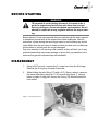
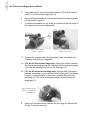
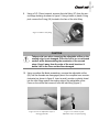
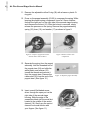
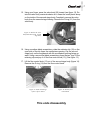
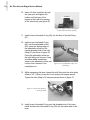
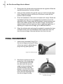
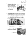
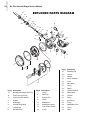
Service Manual
Air Plus Second Stage
Includes XS Series Second Stage
Copyright 2002, Cressi-sub
Revised 3/2002
○ ○ ○ ○ ○ ○ ○
2
Air Plus Second Stage Service Manual
Contents
BEFORE STARTING ....................................................................................... 3
DISASSEMBLY ................................................................................................ 3
PARTS CLEANING AND LUBRICATION ....................................................... 8
CLEANING METAL PARTS ............................................................................................ 8
CLEANING PLASTIC-ONLY PARTS .............................................................................. 8
LUBRICATION ................................................................................................................ 8
Types of Lubricant ..................................................................................................... 8
O-rings ....................................................................................................................... 9
Threaded parts .......................................................................................................... 9
REASSEMBLY ................................................................................................. 9
ADJUSTING THE SECOND STAGE.............................................................. 13
ADJUSTING THE SECOND STAGE WITHOUT AN IN-LINE ADJUSTMENT TOOL. ... 13
ADJUSTING THE SECOND STAGE WITH AN IN-LINE ADJUSTMENT TOOL. .......... 13
FINAL REASSEMBLY ................................................................................... 14
TABLE 1 - TROUBLESHOOTING ................................................................. 17
TABLE 2 - REQUIRED TOOLS ..................................................................... 17
EXPLODED PARTS DIAGRAM..................................................................... 18
○ ○ ○ ○ ○ ○ ○
BEFORE STARTING
WARNING
This manual is not a training document. It is meant to be a
guide for experienced technicians who have also received
factory training at a Cressi-sanctioned repair seminar. Do not
attempt to repair this or any regulator without the proper training.
Before starting, Cressi recommends that you read through the entire manual
to familiarize yourself with all the required tools and techniques. Use this
manual as a guide during the servicing process to avoid missing any critical
steps. Make sure the work area is clean and that you work over a cushioned
work surface so critical parts do not get damaged.
Pay close attention to all warnings and cautions as they will alert you to any
potential hazard that may cause damage or injury. Also, pay attention to the
notes as they provide important tips and reminders.
DISASSEMBLY
1.
Using a 9/16” wrench, unscrew the 2nd stage hose from the first stage.
Remove the O-ring from the end of the hose.
2.
While holding the inlet fitting (27) with a 3/4” (19mm) wrench, unscrew
the swivel hose fitting using an 11/16” wrench (see figure 1). Using a
brass or plastic O-ring pick, remove the O-ring (30) located inside the
hose swivel.
Figure 1. Removing the hose.
3
○ ○ ○ ○ ○ ○ ○
4
Air Plus Second Stage Service Manual
3.
Using side cutters, snip the mouthpiece clamp (12). Pull the mouthpiece (11) off the second stage body (4).
4.
Using a Phillips screwdriver, remove the exhaust tee retaining screw
(10) as shown in figure 2.
5.
To remove the exhaust tee (9), place your thumb on the top corner of
the exhaust tee and press downward.
Figure 2. Removing the
exhaust tee screw
6.
Figure 3. Press down on top corner of
exhaust tee to remove
Remove the exhaust valve (6) by grasping it with your thumb and
forefinger and pulling it straight out.
7a. (For the Air Plus second stage only.) Using your fingers, unscrew
the front cover retaining ring (1b). Separate the front cover assembly
(1a) from the retaining ring. Lift out the diaphragm (3).
7b. (For the XS series second stage only.) Using a small, flat-tipped
jewelers screwdriver, pry out the front cover locking tab (5) as shown
in figure 4. Using the palm of your hand, unscrew the front cover
assembly (1c). Lift out the diaphragm washer (2) and remove the
diaphragm (3).
Figure 4. Removing the
front cover locking tab
(XS series only)
8.
Using an 6 mm hex wrench, unscrew the port plug (8). Remove the
O-ring (7) from the port plug.
○ ○ ○ ○ ○ ○ ○
9.
Using a 3/4” (19mm) wrench, unscrew the inlet fitting (27) from the second stage housing as shown in figure 5. Using a brass or plastic O-ring
pick, remove the O-ring (26) located in the face of the inlet fitting.
Figure 5. Remove inlet fitting
CAUTION
Take special care when removing the adjustable orifice so the
sealing edge is not damaged. Place the orifice on a cushioned
surface while disassembling the remainder of the second
stage. Keep it away from the edge of the work bench so it
doesn’t fall to the floor and become damaged.
10. Using a medium flat-blade screwdriver, unscrew the adjustable orifice
(29) until the threads are disengaged (about five complete turns counterclockwise) as shown in figure 6. Insert a small, wooden or plastic dowel
into the inlet fitting against the sealing edge of the adjustable orifice.
Press on the orifice and remove it from the inlet fitting (figure 7).
Figure 6. Unscrew adjustable orifice to
disengage threads
Figure 7. Use a dowel to push
adjustable orifice out of inlet fitting
5
○ ○ ○ ○ ○ ○ ○
6
Air Plus Second Stage Service Manual
11. Remove the adjustable orifice O-ring (28) with a brass or plastic Oring pick.
12. Press on the poppet assembly (23-25) to compress the spring. While
keeping the poppet spring compressed, insert a 5.5mm nutdriver
through the open port on the right side of the second stage housing
and unscrew the locknut (16). After the locknut is removed, slowly
release the pressure on the spring. Remove the poppet assembly,
spring (22), lever (19), and washer (17) as shown in figure 9.
Figure 8. Compress poppet and remove
locknut with 5.5mm nut driver
13. Separate the spring from the poppet
assembly. Hold the threaded end of
the poppet stem (24) and slide the
white plastic seat retainer (23)
toward the threads and remove it
from the poppet stem. Remove the
rubber seat (25) from the end of the
poppet stem. (See figure 10.)
14. Insert a small flat-bladed screwdriver through the open port on the
right side of the second stage
housing. Slide the edge of the
screwdriver blade into the small slot
located in the middle of the venturi
channel (18). Gently pry the venturi
channel loose and remove with
your fingers. (See figure 11.)
Figure 9. Remove all the valve
components
Figure 10. Separate poppet assembly
Figure 11. Remove venturi
channel
○ ○ ○ ○ ○ ○ ○
15. Using your finger, press the valve body (20) inward (see figure 12). Rotate the valve body counterclockwise so it clears the small plastic bump
on the inside of the second stage body. Completely remove the valve
body from the second-stage housing. Remove the O-ring (21) from the
valve body.
Figure 12. Push in the valve
body and remove from second
stage body
16. Using a medium blade screwdriver, rotate the retaining clip (15) so the
open side of the clip faces the mouthpiece opening. Lay the secondstage body on the workbench with the mouthpiece opening facing upward. Using a second flat blade screwdriver, press the two “legs” of the
retaining clip and pop it off the flow control knob (13). (See figure 13.)
17. Lift the flow control knob (13) out of the second stage body (figure 14).
Remove the O-ring (14) from the flow control knob.
Figure 13. Push on both legs
of the c-clip to remove
Figure 14. Remove flow
control knob
This ends disassembly
7
○ ○ ○ ○ ○ ○ ○
8
Air Plus Second Stage Service Manual
PARTS CLEANING AND LUBRICATION
CLEANING METAL PARTS
CAUTION
Keep the adjustable orifice (26) separate from the other
parts while cleaning. If the sealing surface is damaged, the
part will have to be replaced.
1.
Wash all the metal parts in a hot, soapy water solution. Use a soft
bristle toothbrush to clean the threads and remove any flaky corrosion.
2.
After washing in the hot, soapy water, rinse all the parts in fresh
water.
3.
Place the metal parts in an ultrasonic cleaner with an appropriate
cleaning solution. Avoid using harsh acids such as muriatic acid in
ultrasonic cleaners. Clean the parts for 5 to 15 minutes, depending on
the amount of corrosion.
4.
Remove the parts from the ultrasonic cleaner and rinse them in fresh
water. Blow-dry the parts using low-pressure filtered air.
CLEANING PLASTIC-ONLY PARTS
Avoid placing plastic parts in an ultrasonic cleaner with an acidic cleaning
solution. To properly clean plastic parts, perform the same steps listed
above.
1. Wash all the plastic parts in a hot, soapy water solution. Use a soft
bristle toothbrush to clean the threads and remove any flaky corrosion.
2.
After washing in the hot, soapy water, rinse all the parts in fresh
water.
3.
Blow-dry the parts using low-pressure filtered air.
LUBRICATION
Types of Lubricant
Cressi recommends using only food-grade silicone grease or, more preferably, Christo-lube MCG 111.
○ ○ ○ ○ ○ ○ ○
CAUTION
DO NOT use spray silicones as the aerosol propellants may
chemically attack the rubber compound.
O-rings
All O-rings should be treated with a thin film of lubrication. Do not over-lubricate the O-rings with large amounts of grease. Simply place a small amount
of grease between your thumb and forefinger and run the O-ring between
them.
Threaded parts
You may lightly lubricate the first two threads. As you tighten parts together,
the lubricant will spread to the other threads.
REASSEMBLY
1.
Install a new, lubricated O-ring (14) onto the flow control knob (13). Insert
the flow control knob into the second-stage body and press down so that
the groove for the retaining clip is visible in the mouthpiece opening.
2.
Hold the second stage body with the flow control knob facing downward.
One side of the retaining clip (15) has a sharp edge; the other side has a
rounded edge. Set the retaining clip into the mouthpiece opening with
rounded edge against the 2nd stage housing and the open side against
the flow control knob. Using your finger or a flat blade screwdriver, press
the retaining clip against the flow control knob until it snaps into place
(figure 15). Move the flow control knob back and forth to ensure that it
operates smoothly.
Figure 15. Install C-clip
9
○ ○ ○ ○ ○ ○ ○
10
Air Plus Second Stage Service Manual
3.
Insert the stem of a new exhaust valve (6) through the center hole in
the exhaust port on the outside of the 2nd stage housing (4) as shown
in figure 16. Grasp the stem with your fingers and pull it until the barb
pops through (figure 17).
Figure 16. Install exhaust valve
Figure 17. Pull barb all the way
through
4.
Install a new, lubricated O-ring (21) onto the valve body (20).
5.
The valve body has an air outlet hole located in one corner of the
square face. Place the valve body into the second stage body with
the air outlet hole against the back wall of the 2nd stage housing and
pointing upward toward the mouthpiece (figure 18). Press the inlet
fitting into place, making sure that the squared face is pressed
against the 2nd stage housing.
Figure 18. Valve body
installed
6.
Air outlet
hole
Inside the second stage housing, just above valve body is the slot for
the venturi channel (18). Slide the venturi channel all the way into the
slot until it sits against the back wall of the second stage housing and
covers the air outlet hole (figure 19).
Figure 19. Venturi
channel installed
○ ○ ○ ○ ○ ○ ○
7.
Insert the threaded end of the poppet stem (24) into the squared side of
the seat retainer (23) as shown in figure 20. Press a new rubber seat
(25) into the seat retainer as shown in figure 21.
Figure 20. Insert poppet stem into seat
retainer
8.
Figure 21. Press new LP seat into seat
retainer
Place the spring (22) over the poppet stem so it rests against the seat
retainer. Insert the poppet/spring assembly, threaded end first, into the
threaded (open) side of the valve body. Press inward on the poppet to
compress the spring (figure 22). Place the washer (17) over the end of
the poppet and thread the locknut (16) onto the end of the poppet (figure
23).
Washer
Locknut
Figure 22. Install spring onto poppet
and compress into valve body
9.
While keeping the poppet compressed, install the “feet” of the
lever behind the washer and into
the groove in the face of the valve
body as shown in figure 24.
Figure 24. Lever installed
Figure 23. Install washer followed by
locknut
11
○ ○ ○ ○ ○ ○ ○
12
Air Plus Second Stage Service Manual
10. Insert a 5.5mm nutdriver through
the open port and tighten the
locknut until the face of the
poppet is flush with the opening
of the valve body (see figure 25).
Figure 25. Tighten locknut until poppet
is flush with valve body opening
11. Install a new, lubricated O-ring (26) into the face of the inlet fitting
(27).
12. Install a new, lubricated O-ring
(28) onto the adjustable orifice
(29). Insert the sealing edge of
the adjustable orifice into the
coarse-threaded side of the inlet
fitting (27) as shown in figure 26.
Press the adjustable orifice into
the inlet fitting until it stops. Using
a medium blade screwdriver,
screw in the adjustable orifice until
it stops, then unscrew it two
complete turns.
Figure 26. Press adjustable orifice into
inlet fitting
13. While depressing the lever, thread the inlet fitting into the valve body.
Attach a 3/4” (19mm) crows-foot to an inch-pound torque wrench.
Tighten the inlet fitting to 60 inch-pounds as shown in figure 27.
Figure 27. Torque inlet fitting to
60 inch-pounds
14. Install a new, lubricated O-ring onto the threaded end of the hose;
install another new, lubricated O-ring (30) into the swivel end of the
hose.
○ ○ ○ ○ ○ ○ ○
ADJUSTING THE SECOND STAGE
A medium pressure air supply of 135±5 is required to properly adjust the
second stage. Make sure the first stage that you are using is properly adjusted before performing the second stage adjustments. Please refer to the
appropriate Cressi first stage repair manual for proper first stage adjustment
procedures. The first stage should be attached to a fully charged cylinder
(2500 to 3000 psi).
The use of an in-line adjustment tool makes adjusting the adjustable orifice
easier, but is not required. In-line tools are available from other 3rd party suppliers. Both adjustment methods are outlined below.
ADJUSTING THE SECOND STAGE WITHOUT AN IN-LINE ADJUSTMENT
TOOL.
1.
Screw the threaded end of the hose into the first stage. Using an 11/16”
wrench, tighten the hose until snug. Thread the swivel end of the hose
onto the second stage inlet fitting until finger tight.
2.
Slowly open the cylinder valve and pressurize the regulator. When the
regulator pressurizes, the lever will drop.
3.
Insert a 5.5mm nutdriver through the open port on the second stage
body. Tighten the locknut until the top of the lever is even with the bottom
of the first (lowest) thread.
4.
Turn off the cylinder valve and depressurize the regulator by pressing on
the lever. Unscrew the hose from the second stage. With a medium blade
screwdriver, turn the adjustable orifice counterclockwise about 1/8 turn
(45°). Thread the hose onto the second stage.
5.
Slowly open the cylinder valve and listen for an audible air leak from the
second stage.
6.
If there is no leak, repeat steps 4 & 5 until a leak is heard. If there is a
leak, close the cylinder valve, remove the hose from the second stage
and turn the adjustable orifice clockwise an eighth of a turn (45°). If
adjusting the XS octopus, go an addition half turn (180°).
ADJUSTING THE SECOND STAGE WITH AN IN-LINE ADJUSTMENT
TOOL.
1.
Screw the threaded end of the second stage hose into the first stage.
Using an 11/16” wrench, tighten the hose until snug. Pull back the adjustment wheel of the in-line tool and thread the in-line tool into the second
stage inlet fitting. Thread the swivel end of the second stage hose onto
the in-line tool until finger tight.
13
○ ○ ○ ○ ○ ○ ○
14
Air Plus Second Stage Service Manual
2.
Slowly open the cylinder valve and pressurize the regulator. When the
regulator pressurizes, the lever will drop.
3.
Insert a 5.5mm nutdriver through the open port on the second stage
body. Tighten the locknut until the top of the lever is even with the
bottom of the first thread.
4.
Press the handwheel of the in-line tool inward until it stops. Rotate the
handwheel until the in-line tool engages the screwdriver slot in the
adjustable orifice. Slowly rotate the handwheel counterclockwise until
there is an audible air leak. Once the leak is heard, turn the handwheel clockwise until the leak stops, then an additional eighth turn. If
adjusting an octopus second stage, go an additional half turn.
5.
Close the cylinder valve and purge the regulator by pressing the lever.
Pull back on the in-line tool handwheel and unscrew the in-line tool
from the second stage. Unscrew the hose from the in-line tool.
FINAL REASSEMBLY
1.
Install a new, lubricated O-ring (7) on
the second stage port plug (8). Using
a 6mm hex wrench, tighten the port
plug until snug (see figure 28).
Figure 28. Install port plug
2.
Note the two notches at the top
and bottom of the diaphragm
(3). These notches mate with
two tabs inside the second
stage housing (see figure 29).
On the backside of the diaphragm is a metal strike plate.
With the strike plate facing the
lever, place the diaphragm into
the second stage housing.
Tab
Notch
Figure 29. Align notches in diaphragm
with tabs in housing
○ ○ ○ ○ ○ ○ ○
3a. (Air Plus second stage only.)
Orient the front cover so the purge
button logo is properly aligned.
Align the notches in the front cover
with the tabs in the second stage
(figure 30). While holding the front
cover down with your thumb,
screw the retaining ring onto the
second stage housing.
Tab
Notch
Figure 30. Align notches in front cover with
tabs in housing (Air Plus second stage only)
3b. (XS second stages only.) Lay the washer (2) on top of the diaphragm.
Before installing the front cover, notice the hole in the threads on the
right side of the front cover (see figure 31). This hole will align with the
hole in the second stage body. Thread the front cover onto the second
stage body until the two holes align (the front cover logo should be properly aligned). Press the locking tab (5) into the second stage body (figure
32). Try to unscrew the front cover. If it does not turn, that means the
locking tab is installed correctly.
Figure 31. Holes in front cover and housing
line up when cover screwed in
4.
Figure 32. Press locking tab into place to
secure front cover
Hang the exhaust tee (9) from the top
edge of the flange (see figure 33).
Press on the bottom of the exhaust
tee until it snaps into place.
Figure 33. Hang exhasut tee
on top edge of flange
Hang tee from this
ledge
15
○ ○ ○ ○ ○ ○ ○
16
5.
Air Plus Second Stage Service Manual
Using a Phillips screwdriver, install the exhaust tee retaining screw (10).
Note: Do not install the mouthpiece at this time if you will be performing bench tests.
6. Install the mouthpiece onto the 2nd stage body. Secure the mouthpiece with a new
clamp (12). The clamp’s locking tab should be positioned on the hose side of the
mouthpiece. Using side cutters, trim the clamp so it is flush with the locking tab.
7.
Thread the hose swivel onto the inlet fitting until finger tight. Attach an 11/16” crowsfoot to a torque wrench. While holding the inlet fitting with a 3/4” (19mm) wrench,
tighten the hose swivel to 40 inch-pounds.
This ends reassembly and testing
○ ○ ○ ○ ○ ○ ○
TABLE 1 - TROUBLESHOOTING
Problem
Cause
Solution
Air leak at hose swivel
a. O-ring (26) worn or damaged
b. O-ring (25) worn or damaged
a. Replace O-ring
b. Replace O-ring
Second stage leaks air
a. Adjustable orifice (29) damaged a. Replace adjustable orifice
b. O-ring (28) damaged or worn
b. Replace O-ring
c. LP seat (25) Damaged or worn
c. Replace seat
d. Locknut (16) tightened too much d. Loosen locknut
Hard to breathe
a. Locknut (16) too loose
b. Adjustable orifice (29) in too far
a. Tighten locknut
b. Back out adjustable orifice
TABLE 2 - REQUIRED TOOLS
Tool Description
1.
9/16” open end wrench
2.
3/4” open end wrench
3.
Side cutters
4.
Phillips screwdriver
5.
Flat blade jeweler’s screwdriver
6.
6mm hex wrench
7.
O-ring tool
8.
2 medium blade screwdrivers
9.
Small wooden dowel
10.
5.5mm nut driver
10.
Torque Wrench
11.
9/16” crows-foot
12.
3/4” crows-foot
Used for
Removing hose (31)
Removing inlet fitting (27)
Removing mouthpiece clamp (12)
Removing/installing exhaust tee screw (10)
Removing locking tab (5)
Removing/installing port plug (8)
Removing O-rings
Removing adjustable orifice (29), Clip (15)
Removing adjustable orifice (29)
Removing/installing locknut (16)
Tightening inlet fitting (27); Hose swivel (31)
Used with torque wrench
Used with torque wrench
17
○ ○ ○ ○ ○ ○ ○
18
Air Plus Second Stage Service Manual
EXPLODED PARTS DIAGRAM
31
30
29
27
26
12
25
28
24
23
13
22
21
18
11
14
20
17
15
16
10
19
9
5
4
3
6
7
8
1b
1a
2
1c
Key # Description
Key # Description
Key # Description
15.
Retaining Clip
16.
Locknut
17.
Washer
18.
Venturi Channel
19.
Lever
20.
Valve Body
21.
O-ring
22.
Spring
23.
LP Seat Retainer
O-ring
24.
Poppet Stem
1a.
Retaining Ring Assy (Air Plus)
7.
1b.
Front Cover (Air Plus)
8.
Port Plug
25.
LP Seat
1c.
Front Cover (XS Series)
9.
Exhaust Tee
26.
O-ring
2.
Washer
10.
Screw
27.
Inlet Fitting
3.
Diaphragm
11.
Mouthpiece
28.
O-ring
Second Stage Body
12.
Mouthpiece Clamp
29.
Adjustable orifice
Locking Tab
13.
Flow Control Switch
30.
O-ring
Exhaust Valve
14.
O-ring
31.
Hose
4.
5.
6.
○ ○ ○ ○ ○ ○ ○
19
Air Plus Second Stage
Service Manual
PROFESSIONAL UNDERWATER EQUIPMENT
1 Charles Street, Westwood, NJ 07675
Tel: 800-338-9143 Fax: 800-493-2680