1
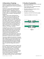
Torsiflex-I Coupling
P-5022-TBW
Service & Installation Instructions
An Altra Industrial Motion Company
Contents
1.0
General Notes
1
1.1
Do’s
2
1.2
Don’ts
2
1.3
Description of Coupling
3
1.4
Torsiflex-I Coupling Data
3
2.0
Operating Conditions
4
3.0
Product identification / marking for
non-electrical equipment
5
4.0
Limitations of product use
5
5.0
Product servicing
6
6.0
Maintenance Instructions
6
7.0
Alignment Instructions
6
7.1
Alignment Method
6
7.2
Axial Alignment
7
7.3
Parallel / Radial / Angular Alignment
7
7.4
Installation and Operating
Misalignment Limits
8
7.5
Limited End Float Coupling
9
8.0
Installation Instructions
9
9.0
Removal Instructions
11
It is essential that a competent person carry out
all the instructions contained in the following
documents. Should any problems be anticipated or
encountered then TB Wood’s personnel are available
for site visits or, alternatively, repairs and overhauls
can be undertaken in our facility.
Prior to performing any maintenance work (including
inspections) it is essential that the power supply is
isolated and that no accidental movement of rotating
machinery is possible.
This product is designed for a specific purpose. It
is vital that it is not used for any purpose other than
that for which it is designed and supplied, and that
the limits of it’s capacities, as detailed here or in any
other document, are not exceeded.
The following instructions should be read and
understood prior to starting any assembly or
maintenance work on the Torsiflex-I disc coupling.
Prior to fitting any component, care should be taken
to ensure that it is clean and free from any dirt. When
tightening any bolts or screws, this should be done
evenly, cylinder head fashion, to 50% torque then to
100% torque in the same sequence. Where specified
it is essential that torque-tightening figures are not
exceeded nor should it be allowed for them to be
below specification.
While installing and removing the transmission unit*,
the unit should be supported to ensure that the
weight is not imposed on one side only.
Record the TB Wood’s order number, coupling type
and size and any relevant information for future use.
Contact TB Wood’s for repair work and spare
components.
Do not use any components that are not supplied
or approved by TB Wood’s in the assembly of this
product.
Do not attempt, where the weight of the unit is
excessive, to lift the coupling without the use of lifting
equipment.
The inherent balance of these couplings could be
disturbed if they are allowed to be knocked either
by striking or rolling. Care should be taken when
transporting and fitting to avoid such knocks.This is
particularly important when a coupling is specifically
balanced.
* refer to section 8, figure 3 for definition of
Transmission Unit
No liability will be accepted and any warranty, either
expressed or implied, will be null and void should
any component of whatever kind, including nuts,
bolts and washers, be used in the assembly, or
modifications be made to all or part of the product
which are not supplied, specified or agreed by TB
Wood’s.
2 Ameridrives • Bibby • 512-353-4000
P-5022-TBW • 4/15
1.3 Description of Couplings
The Torsiflex-I coupling is of the dry disc type.
Flexibility is obtained by the deformation of the disc
packs, within defined limits, which are separated by a
tubular spacer.
Individual discs are of regular polygonal profiles,
which are assembled into a stack of previously
designated thickness, supported by washers on
each side. Flexibility is accomplished by connecting
through the holes, on a common bolt circle diameter,
by means of bolts, alternately, to driving and driven
components.
The bolts, washers and associated holes are
machined to close limits associated with “fitted
bolts”. Due to the need for reasonable ease of
assembly, interference fits are undesirable and,
consequently, tolerances are such as to allow for a
close slide or slight transition fit. To compensate for
these clearances and to ensure the best possible
concentricity between components, the bolt circle
diameter of the bolt holes in the flexible element is
made smaller than that of the mating holes in the
adjacent components. On assembly, all inherent
clearances are, therefore, eliminated.
Coupling bolts are sized such that they are capable
of inducing a load equivalent to 4 times the tensile
load in the flexible element discs, between driving
and driven bolt, when transmitting the full rated
continuous torque of the coupling. This assumes
a coefficient of friction between the various
components of 0.25 but experience has shown that,
due to the high loads induced, minute compressive
deformation is sufficient to raise this to about 0.3.
1.4 Torsiflex-I Coupling Data
•Specifically designed for the process pump and
general industrial markets.
•Plug-in design allows installation and removal
without disturbing the hubs
•Standard couplings fully compliant with the
requirements of API 610.
•
Incorporates anti-flail feature
•
Compliance with API 671/ ISO 10441 available
•
Large hubs available on first two sizes
Figure 1
The reason for adopting this principle of using large,
highly loaded, bolts is two-fold a) to prevent interface
slip, as already mentioned, and b) to eliminate any
chance of bolt bending due to the overhung radial
loading imposed by the flexible element. Avoiding
either slip or bending helps to avoid fretting which
occurs when bolts are designed only to drive in
shear.
Pairs of coupling washers are used to “sandwich the
disc packs”, one thin, (the element washer), and one
thick, (the overload washer). The overload washers
locate in close clearance holes in the coupling
adaptor plates. In the unlikely event of a severe
overload the overload washers will contact the side
of the clearance hole, thus preventing failure of the
elements and ensuring drive is maintained.
In general, the design is identical to a large number of
units supplied and fitted for many years by Turboflex.
Ameridrives • Bibby • 512-353-4000
P-5022-TBW • 4/15 3
Table 1
3 Product identification/marking for non-electrical
equipment.
2 Operating Conditions
In operation the flexible elements are subjected to
both tensile and bending stresses, each having an
influence on the allowable magnitude of the other.
It is important, therefore, that the operating limits
of the various deflections for which the coupling
is designed to accommodate, are kept, as far as
practicable, within those indicated on the “Allowable
Misalignment Curve”.
In practice, the initial alignment of the coupling
should be as close as possible and within the
alignment limits given in the section 8.0 “Installation
Instructions”. This will allow for changes during
operation to remain within allowable limits.
As the Ameridrives • Bibby units are designed to
transmit the torque in friction between the driving
and driven bolts and the flexible elements, it is
essential that, should the need arise, these bolts
should be correctly tightened to the torque indicated
on the assembly drawing or in the “Installation and
Maintenance Instructions”.
Torque and speed should remain within the originally
specified conditions.
Scope: Torsiflex-I Disc Coupling Assemblies,
excluding component spares.
Equipment manufactured or supplied by Ameridrives
• Bibby is marked legibly and indelibly, in a variety
of ways, with the following (subject to contractual
obligations permitting): •
Name and telephone number of manufacturer
•Designation of the series or type and size
(Part Number)
•Contract/Order Number and if applicable the
unique serial number
If applicable, for equipment intended for use in
potentially explosive atmospheres, the following will
be marked on the equipment in accordance with the
ATEX Directive 94/9/EC and EN 13463-1
•
Name and address of manufacturer
•Designation of the series or type and size
(Part Number)
•Contract/Order Number and if applicable the
unique serial number
•
CE Mark.
•
Year of construction
•Document of Conformity identification to ATEX
Directive
4 Ameridrives • Bibby • 512-353-4000
P-5022-TBW • 4/15
The specific marking of explosion protection
followed by the symbol of the equipment group and
category
•The letter ‘G’ (concerning explosive
atmospheres caused by gases, vapors or mists);
and/or the letter ‘D’ (concerning explosive
atmospheres caused by dust)
•
The letter ‘c’ for constructional safety
•The ambient temperature range when different to
-328° F to 725° F (–200° C to 400° C)
4 Limitations of product use
Unless otherwise agreed with Ameridrives • Bibby,
these products must be selected in accordance
with the recommended selection procedure and
must only be used within the performance criteria
set out below: - The rated torque capacities, which
are stated in the product catalogue and/or product
arrangement drawing. A continuous temperature
range of -4° F (-20° C) to 300° F (149° C) within the
permissible operating limits for angular, radial and
axial misalignment, section 7.5, Table 4, and standard hardware. High temperature designs available for temperatures up to 536° F (280° C).
5 Product servicing
Although with proper selection and careful
installation a long working life and very high degree
of operational safety can be expected, we would
recommend that for ATEX certified couplings the
element assembly, coupling bolts and attachment
screws are replaced at 50000 operational hour
intervals.
The operation of a damaged coupling in a hazardous
area is contrary to ATEX and in doing so becomes
an explosive hazard and is wholly the end users
responsibility.
6 Maintenance Instructions
General maintenance of the coupling consists of
a check of the following during normal machinery
maintenance schedules. API617 references this time
period as 3 years for compressor applications.
this inspection is still possible without disturbing
the element bolting. The element packs should be
replaced at the earliest opportunity should cracking / damage be detected.
Ameridrives • Bibby uses self locking nuts. This gives
a high level of performance over many reinstallations.
Note: Any requirement for spare parts should be made quoting
the original purchasers original purchase order number and the
coupling serial number. (This will be etched on the major coupling
flanges) and will appear on all documentation.
7 Alignment Instructions
Torsiflex-I will accept substantial amounts of
misalignment, the configuration of each individual
unit defining the actual acceptable level. The
allowable misalignment is shown graphically on a
curve section
7.4. This curve shows the maximum permitted level
of misalignment for operation and is NOT intended to
define set up limits.
7.1 Alignment Method:
Each company has its own method for aligning
machinery all of which are well documented in both
internal and freely available documents and books.
Hence it is not our intention to describe methods
for setting machines. Instead, the following gives
guidelines for quick checks for alignment suitable
after initial installation and for general maintenance
checks.
7.2 Axial Alignment
The suggested limits for axial set up distance
between the machinery shafts are as shown in Table
2.
Table 2
Sizes
No. of Bolts
TFI0027 to TFI1310
6
Tolerance on DBSE
+ 0.012 in
TFI1900 to TFI2500
8
+ 0.010 in
Axial, Angular & Parallel misalignment to ensure that
these are still within the acceptable limits and that no
major movements have occurred.
All bolts to ensure that they are correctly
tightened.
Inspect the flexible elements visually -for signs of
fatigue cracking local to the washer anchoring points
or general signs of fretting corrosion. Slight bowing or
“S” like distortion is not detrimental to the operation
of the unit. Note that any cracking will begin at the
outermost edge of the outside blade. This means that
Ameridrives • Bibby • 512-353-4000
P-5022-TBW • 4/15 5
7.3 Parallel / Radial / Angular Alignment;
Having basically aligned the machinery shafts using
one of the established techniques, the coupling may
be installed as per the instructions. It is then worth
performing a check to establish that the overall alignment is correct for the particular coupling. This
may be simply performed by one of the following two
methods:
7.4 Installation and Operating Misalignment Limits
The following curve shows the general allowable running misalignment limits
Attach a dial indicator securely to the back of one of
the coupling flanges, with the needle in contact with
the flange face the other side of the flexible element
as near the outside periphery as possible. Rotate the
machinery & coupling and locate the minimum reading position. At this position, set the dial reading
to zero. Rotate the machinery again and record the
maximum reading over 360 degrees. Divide this maximum value by the coupling flange diameter to
gain a value in in/in, which should be no greater than
that shown in Table 3. (This should be repeated at
both flexible elements in a spacer coupling).
An alternative method is, where possible, to accurately measure the distance across the
flanges that sandwich the flexible element (element
gap) to obtain a maximum and minimum value.
The difference between these two values should
be divided by the flange outside diameter to obtain
a value in in/in, which should be no greater than that
shown in Table 3. (This should be repeated at both
flexible elements in a spacer coupling).
Table 3
Sizes
No. of Bolts
TFI0027 to TFI1310
6
Tolerance Element Gap
+ 0.003 in/in
TFI1900 to TFI2500
8
+ 0.002 in/in
Figure 2
See next page to identify reference points
1. Combined angular/radial misalignment
2. 1 degree angle is equivalent to 0.17 in/in
3. At zero speed (Static)
4. At maximum speed and continuous rated torque
The coupling shall operate within this envelope (below
the allowable misalignment curve) and providing these
limits are not exceeded at any time, the coupling should
enjoy a trouble free life.
NOTE: These values are intended as guides only and, in certain
cases, may be exceeded. IF IN DOUBT, CONTACT Ameridrives • Bibby.
6 Ameridrives • Bibby • 512-353-4000
P-5022-TBW • 4/15
Table 4 - TFI Misalignment Data
Coupling
Size TFI
Max. Angular
Misalignment (Deg.)
Bending Moment
(ft.lb./deg.)
Point A (1) (2)
(4)
Max. Axial Deflection (Zero
Angular Misalignment) (in.)
Max. Axial
Thrust (lbf.)
Max. Axial Deflection at full
Angular Misalignment (in.)
Point C (3)
Per Element
Axial Thrust
(lbf.)
Point B (4)
Per Assembly
27
0.5
23
.067
126
.019
15
38
0.5
20
.087
112
.019
9
140
0.5
20
.106
287
.019
20
260
0.5
30
.130
542
.024
28
400
0.5
66
.169
917
.055
112
750
0.5
108
.197
1380
.071
202
1310
0.5
164
.236
1971
.087
292
1900
0.33
277
.197
2473
.059
337
2500
0.33
369
.212
2900
.067
337
3300
0.33
435
.236
3518
.071
405
6000
0.33
704
.295
5170
.094
607
8500
0.33
1025
.319
7531
.110
1124
12000
0.33
1261
.354
8587
.118
1124
7.5 Limited End Float Couplings
N.B. In the case of special limited end float (LEF)
versions the amount of axial movement is physically
restricted and therefore the values shown in the
above table do not apply. In these cases please refer
to the coupling drawing for reference to the amount
of axial movement the coupling is capable of.
For general Safety, Alignment and Maintenance Instructions see other sections of this manual. IMPORTANT: The main Coupling Bolts/Nuts at
both ends are tightened by Ameridrives • Bibby,
and should, under normal circumstances, NOT BE
TOUCHED unless specified in the installation instructions.
8.0 Installation Instructions
No liability will be accepted, and any warranty, either
expressed or implied, will be null and void should any
components of whatsoever kind, including nuts, bolts
and washers, be used in the assembly or any modifications be made to all or part of the unit which are not supplied, specified or agreed by Ameridrives • Bibby.
When tightening any other bolt or screw, this should
be done evenly, i.e. cylinder head fashion, to 50%
torque then to 100% torque in the same sequence.
Threads should be lubricated with Molybdenum Disulphide grease or equivalent. Reference table 6 for tightening torques.
Ameridrives • Bibby • 512-353-4000
P-5022-TBW • 4/15 7
Check that the parallel & and axial misalignments
of the shafts are within the limits defined in the
alignment curves, section 7.4, Figure 2. Ameridrives
• Bibby do not recommend any specific alignment
method as this varies due to personnel preference;
however the alignment should be within the
operational envelope shown on the misalignment
curve.
8.1 Reference any applicable drawings for sizes and
dimensions. Ensure that all required tools and equipment are available.
8.2 The coupling is supplied in an assembled state
with its misalignment capabilities locked by installation screws near the element packs. The coupling is packed appropriately for transportation
and storage. Inspect the coupling for:
•Indication of deviation from specification to
ensure that it conforms to requirements.
•
Potential damage due to transportation.
8.3 For balanced couplings, note any match
markings, which must be aligned when the coupling
is installed.
8.4 The Torsiflex-I coupling hubs must be removed
from the transmissions unit – see figure 3. to allow
installation. Remove the connecting nuts and bolts
from the hub/adaptor flanges and using jacking
screws force the flanges apart. Store the nuts and
bolts along with the packing ring and shims (if
supplied) for future stages of installation.
8.5 The hubs may now be fitted to the driver and
driven shafts. The method of fitting will be dependant
on the type of fit specified for the particular
installation. In all cases the hub face should be in line
with the shaft end.
Where hub/shaft connections require a standard
interference fit the hubs may be heated in an oil
bath or oven at 392-482° F (200-250° C) and rapidly
positioned on the shaft. It is essential that this heat
is evenly applied over the whole hub and that spot
heating is avoided. Ensure that one shaft rotates so
that the coupling match marks can be aligned.
8.6 Check the shafts misalignments and DBSE (distance between shaft ends) are within allowable
limits. (Reference Section 7.4).
8.7 The main bolts in the transmission unit are factory assembled and must not be disturbed. Undo
the installation screws; the coupling should now be in
a relaxed state.
If no packing ring or shims are supplied, go to step
8.12.
8.8 Measure the free length of the transmission
unit. Add to this the thickness of the packing plate.
Record this value as X.
Figure 3: Coupling Construction
Component Parts
1.Hubs
2.Spacer
3.Adaptor
4. Element Washer
5. Element Washers
6. Element Blades
7. Coupling Bolt
8. Coupling Nuts
9. Attachment Screws
10. Installation Screws
11.Shims
12. Packing Plate
8 Ameridrives • Bibby • 512-353-4000
8.9 Now measure the distance between the shaft
ends (DBSE) of the machinery. Adjust this length by either subtracting pre-stretch or adding pre-compression. Record this value as Y
8.10 Calculate the required number of shims from the
following equation
Number of shims = (Y-X) ÷ shim thickness
Round this value to a whole number of shims. Shim
thickness is 0.015 inches.
P-5022-TBW • 4/15
8.11 Fit shims between packing ring and the transmission unit. Ensure match marks are aligned.
8.17 Ensure all match marks are aligned, all tooling is
removed and inspect the coupling before operation.
8.12 Install the installation screws Ref 10, and tighten
in cylinder head fashion, maintaining parallelism between the flange faces of the adaptor and spacer,
until both elements packs are compressed by a minimum required amount to allow the transmission
unit to be put into position. Do not compress the elements beyond the value stated in “Maximum Element Compression” Values. These values express
the maximum amount of compression allowed per
element pack. However, it is recommended to use
the minimum amount of compression required when
installing couplings.
9.0 Removal Instructions.
Coupling removal is a reverse of the above
installation process ensuring that, upon reinstallation, the above process is again followed in
careful sequence.
Table 5
Coupling Size TFI
Maximum Compressions (in) per
element pack
27
0.059
38
0.069
140
0.079
260
0.090
400
0.090
750
Table 6 : When tightening any other bolt or screw, this
should be done evenly, i.e. cylinder head fashion, to
50% torque then to 100% torque in the same sequence. Threads should be lubricated with Molybdenum Disulphide grease or equivalent
IMPORTANT: The main Coupling Bolts/Nuts at
both ends are tightened by Ameridrives • Bibby,
and should, under normal circumstances, NOT BE
TOUCHED unless specified in the installation instructions
Table 6
Disc Pack Bolting
Bolt Stretch
Alternate Bolt
Torque
Hub
Attachment
Screw
(in)
(ft* lb)
(ft* lb)
0.0014
7
7
0.0014
7
17
140
0.0028
33
7
260
0.0031
55
17
0.118
400
0.0031
83
17
0.138
750
0.0041
166
32
8500
0.138
1310
0.0044
273
53
12000
0.157
1900
0.0038
273
53
2500
0.0044
354
133
3300
0.0057
553
133
6000
0.0068
811
258
8500
0.0077
1401
350
12000
0.0091
1844
467
Coupling
Size
0.098
27
1310
0.118
38
1900
0.118
2500
0.118
3300
6000
8.13 Position the transmission unit between the shaft
ends (hub faces), ensuring match marks are aligned.
8.14 Fit and tighten in cylinder head fashion the connecting bolts that pass through the packing ring
and shims. Reference table 6 for tightening torques.
8.15 Release and remove the installation screws.
8.16 Fit and tighten in cylinder head fashion the attachment screws that pass through the remaining
flange. If a pre-stretch is present, it may be necessary
to pull the flanges together using the attachment
screws. Reference table 6 for tightening torques.
Ameridrives • Bibby • 512-353-4000
P-5022-TBW • 4/15 9
TORSI-LOCK
Shrink Disc
Mounting Instructions
Notes: The shrink rings are supplied assembled and
ready to mount. Only the larger units, where the
weights involved make handling difficult, should be
disassembled to facilitate mounting.
Mounting Instructions
Screws
(Grade 10.9)
Wrench SIZE
(mm)
Tightening Torque
Nm
ft.lb
M5
8
5
3.6
M6
10
12
8.7
M8
13
30
22
M10
17
59
44
M12
19
100
74
M16
24
250
185
M20
30
490
362
M24
36
840
620
1. Remove any spacers which may have been ar
ranged between the pressure rings as protection during transport.
2. The screws should only be tightened to such a degree that the inner ring can still be turned freely.
3. Apply grease to the surface of the hub on which the shrink ring seats.
4.
Push the shrink ring onto the hub.
Attention: Do not begin tightening the screws before the shaft is in place in the hub bore, otherwise permanent deformation will result.
5. Push the hub onto the shaft, both contact surfaces beeing ungreased.
Disassembly
1.Loosen the screws evenly one after the other, again going round several times to avoid canting 6. Make sure the shrink ring is aligned, i.e. the pressure rings are in parallel planes, by tightening of the plates on the inner ring.
the screws with a short wrench.
7. Tighten the ring by tensioning the screws evenly one after the other in a clockwise direction (not in a “crosswise” fashion). It will be necessary to go round several times before all the screws are torqued down to the recommended value. (For torque val
ues and required wrench lenghts see table). Check with a torque wrench. The tightening torque is either punched into the material with smaller units, or is indicated on a plate.
10 Ameridrives • Bibby • 512-353-4000
Under no cicumstances whatsoever should the screws be totally disengaged, since this could lead to a ring jumping off. (think safety)
2. Before the shaft is dismantled or the hub pulled off, any rust on the hub or shaft should be removed.
3. Remove the shrink ring from the hub.
P-5022-TBW • 4/15
Cleaning and Regreasing
Shrink rings which have been in service should be
totally dismantled and cleaned. The bevel surfaces
are factory lubricated with a solid lubricant (e.g.
Weicon, “Anti-Seize”).
Undamaged bevel surfaces should be regreased only
with “Anti-Seize”, which should likewise be applied to
threads and screw-head bearing surface.
Ameridrives • Bibby • 512-353-4000
P-5022-TBW • 4/15 11
An Altra Industrial Motion Company
www.tbwoods.com
2000 Clovis Barker Road
San Marcos, TX 78666
512-353-4000
Fax: 512-353-4017
P-5022-TBW
4/15
www.altramotion.com
Printed in USA