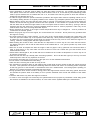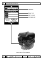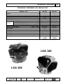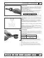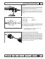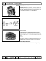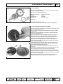
1
WORK SHOP
MANUAL
LGA 280-340 OHC Series engines,code 1-5302- 528
LGA 280 OHC
LGA 340 OHC
1st Edition
SERVICE
COMPILER TECO/ATI
REG. CODE
MODEL N°
DATE OF ISSUE
REVISION
1-5302-528
50805
31.07.2001
00
DATE
31.07.2001
ENDORSED
1
PREFACE
Every attempt has been made to present within this service manual, accurate and up to date technical information.
However, development on the Lombardini series is continuos. Therefore, the information within this manual is subject
to change without notice and without obligation.
The information contained within this service manual is the sole property of Lombardini. As such, no reproduction or
replication in whole or part is allowed without the express written permission of Lombardini.
Information presented within this manual assumes the following:
1- The person or persons performing service work on Lombardini series engines is properly trained and equipped to
safely and professionally perform the subject operation;
2- The person or persons performing service work on Lombardini series engines possesses adequate hand and
Lombardini special tools to safely and professionally perform the subject service operation;
3- The person or persons performing service work on Lombardini series engines has read the pertinent information
regarding the subject service operations and fully understands the operation at hand.
GENERAL SERVICE MANUAL NOTES:
1- Use only genuine Lombardini repair parts. Failure to use genuine Lombardini parts could result in sub-standard
performance and low longevity.
2- All data presented are in metric format. That is, dimensions are presented in millimeters (mm), torque is presented
in Newton-meters (Nm), weight is presented in kilograms (Kg), volume is presented in liters or cubic centimeters
(cc) and pressure is presented in barometric units (bar).
SERVICE
WARRANTY CERTIFICATE
WARRANTY CERTIFICATE
Engine manufactured by Lombardini S.r.l., are warranted to be free of defects in workmanship or materials for 12
months from the date of delivery to the first purchaser or non more than two (2) years from date of engine delivery to
the Original Equipment Manufacturer as defined by Lombardini invoicing, whichever occurs firsts, except as defined
below.
Stationary applications, working at constant speed and/or slightly variable speeds, are excluded from the above
terms. Stationary/fixed speed applications will be warranted to be free of material/workmanship defects for a
maximum operational period of 1000 hours or 12months from the date of first purchase, whichever occurs first. The
two (2) year limitation from date of Lombardini invoice will remain intact as described above.
Modification of Lombardini products by the Original Equipement Manufacturer or the end user with respect to cooling
systems, filtration systems, induction systems, exhaust systems, lubrication system, fuel system, fuel system
settings, etc., will require special written warranty agreements. A test certificate/approval by the R&D/Application
engineering department of Lombardini or associated Lombardini companies concerning modified Lombardini products
will entitle Warranty as defined above. Warranty will not be granted on any modified Lombardini product without
special written approval by Lombardini.
Within the above stated periods Lombardini will replace and/or repair, at the option of Lombardini, any part or
component that, upon examination by Lombardini or an authorized Lombardini agent, is found to be defective in
workmanship or materials. Any other responsibility/obligation for different expenses, damages and direct/indirect
losses deriving from the engine use or from both the total or partial impossibility of use, is excluded.
The repair or replacemnt of any component will not extend or renew the warranty period. Direct labor required to make
repairs or to replace components found to be defective in materials or workmanship will be completed at no cost to
the end user. Lombardini in not responsible however for indirect costs of removing/installing the engine assembly.
Further, Lombardini is not responsible for the costs of transportation of the machine or components requiring repair or
for service supplies such as lubricating oils and filters.
Lombardini Warranty obligations will be cancelled if:
- Lombardini engines are applied to a given machine causing working engine parameters outside Lombardini
application guidelines.
- Lombardini engines are not serviced and maintained according to the "USE and MAINTENANCE" booklet.
- Any seal affixed to the engine by Lombardini has been tampered with or removed.
- Engines have been disassembled, repaired or altered by any party other than an authorized Lombardini agent.
- Spare parts used are not original Lombardini.
- Fuel injection system/component failures caused by the use of unauthorized fuel types or poor quality fuels are
not covered under the Lombardini warranty policy.
- Electrical system failures due to the modification of Lombardini supplied harnesses, modification of Lombardini
supplied control panels, OEM/end user supplied/installed relays, controls, etc. are not covered under warranty.
Following expiration of the above stated warranty period(s) and limitations, Lombardini will have no further
responsibility for warranty and will consider our obligation for warranty complete.
The above warranty certificate will be in effect starting July 1, 1993 and cancels/replaces any and all explicit or implicit
warranty policies on the part of Lombardini. The above warranty conditions can from this date forward be modified only
in writing.
COMPILER TECO/ATL
REG. CODE
MODEL N°
DATE OF ISSUE
REVISION
1-5302-528
50805
31.07.2001
00
DATE
31.07.2001
ENDORSED
3
INDEX
This manual gives the main instructions on how to repair LOMBARDINI LGA 280-340 OHC
gasoline-fuelled engines, updated as of 31.07.2001.
INDEX
I
TROUBLE SHOOTING
II
WARNING SIGNS - SAFETY INSTRUCTIONS
"
8-9
III
ENGINE IDENTIFICATION
"
10
IV
TECHNICAL FEATURES
"
11
V
CHARACTERISTICS
"
12
VI
OVERALL DIMENSION
"
13
VII
MAINTENANCE - RECOMMENDED OIL TYPE - REFILLING
"
14
VIII
DISASSSEMBLY/REASSEMBLY
"
17
Page
General information for correct repairs
Engine disassembly
Engine preparation
Flywheel extraction
Head disassembly
Disassembly of camshaft-tappets valves
Timing pulley removal
Timing cover removal
Crankshaft extraction
Cylinder head
Camshaft
Valves - guides - seats - valve spring - tappets
Valves and valve-guides dimensions after assembly in the head
Valves and valve-guides gap
Valve guide
Oil seal ring on valve guide
Valve seats
Valve springs
Tappets
Breather valve
Cylinder
Connecting rod
Piston and rings
Crankshaft
Main journals and crank pin diameter (mm)
Governor and balancing shaft gear command
Balancing shaft
Speed governor
Bearings
Crankcase and timing cover
Recoil starter
Rope and return spring replacement
Oil watch device (optional)
Crancshaft and oil seal rings
Piston and connecting rods
Speed governor
Timing cover
○
○
○
○
○
○
○
○
○
○
○
○
○
○
○
○
○
○
○
○
○
○
○
○
○
○
○
○
○
○
○
○
○
○
○
○
○
○
○
○
○
○
○
○
○
○
○
○
○
○
○
○
○
○
○
○
○
○
○
○
○
○
○
○
○
○
○
○
○
○
○
○
○
○
○
○
○
○
○
○
○
○
○
○
○
○
○
○
○
○
○
○
○
○
○
○
○
○
○
○
○
○
○
○
○
○
○
○
○
○
○
○
○
○
○
○
○
○
○
○
○
○
○
○
○
○
○
○
○
○
○
○
○
○
○
○
○
○
○
○
○
○
○
○
○
○
○
○
○
○
○
○
○
○
○
○
○
○
○
○
○
○
○
○
○
○
○
○
○
○
○
○
○
○
○
○
○
○
○
○
○
○
○
○
○
○
○
○
○
○
○
○
○
○
○
○
○
○
○
○
○
○
○
○
○
○
○
○
○
○
○
○
○
○
○
○
○
○
○
○
○
○
○
○
○
○
○
○
○
○
○
○
○
○
○
○
○
○
○
○
○
○
○
○
○
○
○
○
○
○
○
○
○
○
○
○
○
○
○
○
○
○
○
○
○
○
○
○
○
○
○
COMPILER TECO/ATL
○
○
○
○
○
○
○
○
○
○
○
○
○
○
○
○
○
○
REG. CODE
○
○
○
○
○
○
○
○
○
○
○
○
○
○
○
○
○
○
○
○
○
○
○
○
○
○
○
○
○
○
○
○
○
○
○
○
○
○
○
○
○
○
○
○
○
○
○
○
○
○
○
○
○
○
○
○
○
○
○
○
○
○
○
○
○
○
○
○
○
○
○
○
○
○
○
○
○
○
○
○
○
○
○
○
○
○
○
○
○
○
○
○
○
○
○
○
○
○
○
○
○
○
○
○
○
○
○
○
○
○
○
○
○
○
○
○
○
○
○
○
○
○
○
○
○
○
○
○
○
○
○
○
○
○
○
○
○
○
○
○
○
○
○
○
○
○
○
○
○
○
○
○
○
○
○
○
○
○
○
○
○
○
○
○
○
○
○
○
MODEL N°
○
○
○
○
○
○
○
○
○
○
○
○
○
○
○
○
○
○
○
○
○
○
○
○
○
○
○
○
○
○
○
○
○
○
○
○
○
○
○
○
○
○
○
○
○
○
○
○
○
○
○
○
50805
○
○
DATE OF ISSUE
31.07.2001
○
○
○
○
○
○
○
○
○
○
○
○
○
00
○
○
○
○
○
○
○
○
○
○
○
○
○
DATE
31.07.2001
○
○
○
○
○
○
○
○
○
○
○
○
○
○
○
○
○
ENDORSED
○
○
○
○
○
○
○
○
○
○
○
○
○
○
○
○
○
○
○
○
○
○
○
○
○
○
○
○
○
○
○
○
○
○
○
○
○
○
○
○
○
○
○
○
○
○
○
○
○
○
○
○
○
○
○
○
○
○
○
○
○
○
○
○
○
○
○
○
○
○
○
○
○
○
○
○
○
○
○
○
○
○
○
○
○
○
○
○
○
○
○
○
○
○
○
○
○
○
○
○
○
○
○
○
○
○
○
○
○
○
○
○
○
○
○
○
○
○
○
○
○
○
○
○
○
○
○
○
○
○
○
○
○
○
○
○
○
○
○
○
○
○
○
○
○
○
○
○
○
○
○
○
REVISION
1-5302-528
○
○
○
○
○
○
○
○
○
○
○
○
○
○
○
○
○
○
○
○
○
○
○
○
○
○
○
○
○
○
○
○
○
○
○
○
○
○
○
○
○
○
○
○
○
○
○
○
○
○
○
○
○
○
○
○
○
○
○
○
○
○
○
○
○
○
○
○
○
○
○
○
○
○
○
○
○
○
○
○
○
○
○
○
○
○
○
○
○
○
○
○
○
○
○
○
○
○
○
○
○
○
○
○
○
○
○
○
○
○
○
○
○
○
○
○
○
○
○
○
○
○
○
○
○
○
○
○
○
○
○
○
○
○
○
○
○
○
○
○
○
○
○
○
○
○
○
○
○
○
○
○
○
○
○
○
○
○
○
○
○
○
○
○
○
○
○
○
○
○
○
○
○
○
○
○
○
○
○
○
○
○
○
○
○
○
○
○
○
○
○
○
○
○
○
○
○
○
○
○
○
○
○
○
○
○
○
○
○
○
○
○
○
○
○
○
○
○
○
○
○
○
○
○
○
○
○
○
○
○
○
○
○
○
○
○
○
○
○
○
○
○
○
○
○
○
○
○
○
○
○
○
○
○
○
○
○
○
○
○
○
○
○
○
○
○
○
○
○
○
○
○
○
○
○
○
○
○
○
○
○
○
○
○
○
○
○
○
○
○
○
○
○
○
○
○
○
○
○
○
○
○
○
○
○
○
○
○
○
○
○
○
○
○
○
○
○
○
○
○
○
○
○
○
○
○
○
○
○
○
○
○
○
○
○
○
○
○
○
○
○
○
○
○
○
○
○
○
○
○
○
○
○
○
○
○
○
○
○
○
○
○
○
○
○
○
○
○
○
○
○
○
○
○
○
○
○
○
○
○
○
○
○
○
○
○
○
○
○
○
○
○
○
○
○
○
○
○
○
○
○
○
○
○
○
○
○
○
○
○
○
○
○
○
○
○
○
○
○
○
○
○
○
○
○
○
○
○
○
○
○
○
○
○
○
○
○
○
○
○
○
○
○
○
○
○
○
○
○
○
○
○
○
○
○
○
○
○
○
○
○
○
○
○
○
○
○
○
○
○
○
○
○
○
○
○
○
○
○
○
○
○
○
○
○
○
○
○
○
○
○
○
○
○
17
17
17
17
17
18
18
18
18
18
19
19
19
20
20
20
21
22
22
22
22
23
23-24
25
25
25
26
26
26
26
27
27
28
28
28
29
29
○
○
○
○
○
○
○
○
○
○
○
○
○
○
○
○
○
○
○
○
○
○
○
○
○
○
○
○
○
○
○
○
○
○
○
○
○
○
○
○
○
○
○
○
○
○
○
○
○
○
○
○
○
○
○
○
○
○
○
○
○
○
○
○
○
○
○
○
○
○
○
○
○
○
○
○
○
○
○
○
○
○
○
○
○
○
○
○
○
○
○
○
○
○
○
○
○
○
○
○
○
○
○
○
○
○
○
○
○
○
○
○
○
○
○
○
○
○
○
○
○
○
○
○
○
○
○
○
○
○
○
○
○
○
○
○
○
○
○
○
○
○
○
○
○
○
○
○
○
○
○
○
○
○
○
○
○
○
○
○
○
○
○
○
○
○
○
○
○
○
○
○
○
○
○
○
○
○
○
○
○
○
○
○
○
○
○
○
○
○
○
○
○
○
○
○
○
○
○
○
○
○
○
○
○
○
○
○
○
○
○
○
○
○
4
○
○
○
○
○
○
○
○
○
○
○
○
○
○
○
○
○
○
○
○
○
○
○
○
○
○
○
○
○
○
○
○
○
○
○
○
○
○
○
○
○
○
○
○
○
○
○
○
○
○
○
○
○
○
○
○
○
○
○
○
○
○
○
○
○
○
○
○
○
○
○
○
○
○
○
○
○
○
○
○
○
○
○
○
○
○
○
○
○
○
○
○
○
○
○
○
○
○
○
○
○
○
○
○
○
○
○
○
○
○
○
○
○
○
○
○
○
○
○
○
○
○
○
○
○
○
○
○
○
○
○
○
○
○
○
○
○
○
○
○
○
○
○
○
○
○
○
○
○
○
○
○
○
○
○
○
○
○
○
○
○
○
○
○
○
○
○
○
○
○
○
○
○
○
○
○
○
○
○
○
○
○
○
○
○
○
○
○
○
○
○
○
○
○
○
○
○
○
○
○
○
○
○
○
○
○
○
○
○
○
○
○
○
○
○
○
○
○
○
○
○
○
○
○
○
○
○
○
○
○
○
○
○
○
○
○
○
○
○
○
○
○
○
○
○
○
○
○
○
○
○
○
○
○
○
○
○
○
○
○
○
○
○
○
○
○
○
○
○
○
○
○
○
○
○
○
○
○
○
○
○
○
○
○
○
○
○
○
○
○
○
○
○
○
○
○
○
○
○
○
○
○
○
○
○
○
○
○
○
○
○
○
○
○
○
○
○
○
○
○
○
○
○
○
○
○
○
○
○
○
○
○
○
○
○
○
○
○
○
○
○
○
○
○
○
○
○
○
○
○
○
○
○
○
○
○
○
7
○
○
○
○
○
○
INDEX
Timing pulley assembling
Cylinder head assembling
Camshaft assembling and valve clearance adjustment
Timing adjustement and assembling of the toothed belt
Flywheel assembly and coil gap adjustment
Carburetor
Lubrication
○
○
○
○
○
○
○
○
○
○
○
○
○
○
○
○
○
○
○
○
○
○
IX
○
○
○
○
○
○
○
○
○
○
○
○
○
○
○
○
○
○
○
○
○
○
○
○
○
○
○
○
○
○
○
○
○
○
○
○
○
○
○
○
○
○
○
○
○
○
○
○
○
○
○
○
○
○
○
○
○
○
○
○
○
○
○
○
○
○
○
○
○
○
○
○
○
○
○
○
○
○
○
○
○
○
○
○
○
○
○
○
○
○
○
○
○
○
○
○
○
○
○
○
○
○
○
○
○
○
○
○
○
○
○
○
○
○
○
○
○
○
○
○
○
○
○
○
○
○
○
○
○
○
○
○
○
○
○
○
○
○
○
○
○
○
○
○
○
○
○
○
○
○
○
○
○
○
○
○
○
○
○
○
○
○
○
○
○
○
○
○
○
○
○
○
○
○
○
○
○
○
○
○
○
○
○
○
○
○
○
○
○
○
○
○
○
○
○
○
○
○
○
○
○
○
○
○
○
○
○
○
○
○
○
○
○
○
○
○
○
○
○
○
○
○
○
○
○
○
○
○
○
○
○
○
○
○
○
○
○
○
○
○
○
○
○
○
○
○
○
○
○
○
○
○
○
○
○
○
○
○
○
○
○
○
○
○
○
○
○
○
○
○
○
○
○
○
○
○
○
○
○
○
○
○
○
○
○
○
○
○
○
○
○
○
○
○
○
○
○
○
○
○
○
○
○
○
○
○
○
○
○
○
○
○
○
○
○
○
○
○
○
○
○
○
○
○
○
○
○
○
○
○
○
○
○
○
○
○
○
○
○
○
○
○
○
○
○
○
○
○
○
○
○
○
○
○
○
○
○
○
○
○
○
○
○
○
○
○
○
○
○
○
○
○
○
○
○
○
○
○
○
○
○
○
○
○
○
○
○
○
○
○
○
○
○
○
○
○
○
○
○
○
○
○
○
○
○
○
○
○
○
○
○
○
○
○
○
○
○
○
○
○
○
○
○
○
○
○
○
○
○
○
○
○
○
○
○
○
○
○
○
○
○
○
○
○
○
○
○
○
○
○
○
○
○
○
○
○
○
○
○
○
○
○
○
○
○
○
○
○
○
○
○
○
○
○
○
○
○
○
○
○
○
○
○
○
○
○
○
○
○
○
○
○
○
○
○
○
○
○
○
○
○
○
○
○
○
○
○
○
○
○
○
○
○
○
○
○
○
○
○
○
○
○
○
○
○
○
○
○
○
○
○
○
○
○
○
○
○
○
○
○
○
○
○
○
○
○
○
○
○
○
○
○
○
○
○
○
○
○
○
○
○
○
○
○
○
○
○
○
○
○
○
○
○
○
○
○
○
○
○
○
○
○
○
○
○
○
○
○
○
○
○
○
○
○
○
○
○
○
○
○
○
○
○
○
○
○
○
○
○
○
○
○
○
○
○
○
○
○
○
○
○
○
○
○
○
○
○
○
○
○
○
○
○
○
○
○
○
○
○
○
○
○
○
○
○
○
○
○
○
○
○
○
○
○
○
○
○
○
○
○
○
○
○
○
○
○
○
○
○
○
○
○
○
○
○
○
○
○
○
○
○
○
○
○
○
○
○
○
○
○
○
○
○
○
○
○
○
○
○
○
○
○
○
○
○
○
○
○
○
○
○
○
○
○
○
○
○
○
○
○
○
○
○
○
○
○
○
○
○
○
○
○
○
○
○
○
○
○
○
○
○
○
○
○
○
○
○
○
○
○
○
○
○
○
○
○
○
○
○
○
○
○
○
○
○
○
○
○
○
○
○
○
○
○
○
○
○
○
○
○
○
○
○
○
○
○
○
○
○
○
○
○
○
○
○
○
○
○
○
○
○
○
○
○
○
○
○
○
○
○
○
○
○
○
○
○
○
○
○
○
○
○
○
○
○
○
○
○
○
○
○
○
○
○
○
○
○
○
○
○
○
○
○
○
○
○
○
○
○
○
○
○
○
○
○
○
○
○
○
○
○
○
○
○
○
○
○
○
○
○
○
○
○
○
○
○
○
○
○
○
○
○
○
○
○
○
○
○
○
○
○
○
○
○
○
○
○
○
○
○
○
○
○
○
○
○
○
○
○
○
○
○
○
○
○
○
○
○
○
○
○
Axial load - radial load and maximum overhang
Installation
Inclination and operating limits
○
○
○
○
○
○
○
○
○
○
○
○
○
○
○
○
○
○
○
○
○
○
○
○
○
○
○
○
○
○
○
○
○
○
○
○
○
○
○
○
○
○
○
○
○
○
○
○
○
○
○
○
○
○
○
○
○
○
○
○
○
○
○
○
○
○
○
○
○
○
○
○
○
○
○
○
○
○
○
○
○
○
○
○
○
○
○
○
○
○
○
○
○
○
○
○
○
○
○
○
○
○
○
○
○
○
○
○
○
○
○
○
○
○
○
○
○
○
○
○
○
○
○
○
○
○
○
○
○
○
○
○
○
○
○
○
○
○
○
○
○
○
○
○
○
○
○
○
○
○
○
○
○
○
○
○
○
○
○
○
○
○
○
○
○
○
○
○
○
○
○
○
○
○
○
○
○
○
○
○
○
○
○
○
○
○
○
○
○
○
○
○
○
○
○
○
○
○
○
○
○
○
○
○
○
○
○
○
○
○
○
○
○
○
○
○
○
○
○
○
40
"
○
○
○
○
○
○
○
○
○
○
○
○
○
○
○
○
○
○
○
○
○
○
○
○
○
○
○
○
○
○
○
○
○
○
○
○
○
○
○
○
○
○
○
○
○
XVI PISTON-CYLINDER OVERSIZE TABLE - TOLERANCES OF CRANKSHAFT JOURNAL
GRINDINGS - TABLE OF CLEARANCES AND ADJUSTMENTS
Piston-cylinder oversize table
Tolerances of crankshaft journal grindings
Table of clearances and adjustments
○
○
○
○
○
○
○
○
○
REG. CODE
○
MODEL N°
○
○
○
○
○
○
○
○
○
○
○
○
○
○
○
○
○
○
○
○
○
○
○
○
○
○
○
○
○
○
○
○
○
○
○
○
○
○
○
DATE OF ISSUE
REVISION
1-5302-528
50805
31.07.2001
○
○
○
○
○
○
○
○
○
○
○
○
○
○
○
○
○
○
○
○
○
○
○
○
○
○
○
○
○
○
○
○
○
○
○
○
○
○
○
○
○
○
○
○
○
○
○
○
○
○
○
○
○
○
○
○
○
○
○
○
○
○
DATE
31.07.2001
ENDORSED
○
○
○
42
43
43
43
43
○
○
00
○
42
"
○
39
39
39
40
41
SPECIAL TOOLS
○
39
"
Main torque specifications
Standard bolt torque specifications
38
38
38
○
○
TORQUE SETTING
○
○
○
"
○
○
38
○
INSTALLATION - INCLINATION AND OPERATING LIMITS
36
36
36
37
37
37
○
○
○
○
○
○
○
○
○
○
○
○
○
○
○
○
○
○
○
○
○
○
○
○
○
○
○
○
○
○
○
○
○
○
○
○
○
○
○
○
○
○
○
○
○
○
○
○
○
○
○
○
○
○
○
○
○
○
○
○
○
○
○
○
○
○
○
○
○
○
○
○
○
○
○
○
○
○
○
○
○
○
○
○
○
○
○
○
○
○
○
○
○
○
○
○
○
○
○
○
○
○
○
34
34
34
34
34
35
35
35
35
35
36
"
Storage
Temporary inactivity
Preparation for starting
COMPILER TECO/ATL
○
○
○
STORAGE
Special tools
○
○
○
○
○
○
○
34
○
○
○
○
29
29
30
31
31
32
32
33
33
○
○
○
○
○
○
○
○
○
"
○
○
○
○
○
○
Engine assembling
Governor lever adjustment
Engine test
Starting with the recoil starter
Electric starting
Carburetor and R.P.M. adjustment
○
○
○
REGISTRAZIONI
○
○
○
○
○
○
○
○
○
○
○
○
○
○
○
○
○
○
○
○
○
○
○
○
○
○
○
○
○
○
○
○
○
○
○
○
○
○
○
○
○
○
○
○
○
○
○
○
○
○
○
○
○
○
○
○
○
○
○
○
○
○
○
○
○
○
○
○
○
○
○
○
○
○
○
○
○
○
○
○
○
○
○
○
○
○
○
○
○
○
○
○
○
○
○
○
○
○
○
○
○
○
○
○
○
○
○
○
○
○
○
○
○
○
○
○
○
○
○
○
○
○
○
○
○
○
○
○
○
○
○
○
○
○
○
○
○
○
○
○
○
○
○
○
○
○
○
○
○
○
○
○
○
○
○
○
○
○
○
○
○
○
○
○
○
○
○
○
○
○
○
○
○
○
○
○
○
○
○
○
○
○
○
○
○
○
○
○
○
○
○
XV
○
○
○
"
○
○
○
○
○
XIV
○
○
○
○
○
○
Page 33
○
XIII
○
○
○
○
○
○
○
○
○
○
○
○
○
○
○
○
○
○
○
○
○
○
○
○
○
○
○
○
ELECTRIC STARTING
○
XII
○
○
○
○
○
Electric starting
Electrical start system standard
System checks
Alternator
Rectifier
Starting motor
Battery
Starting panel
Lighting system with alternator
Characteristics with alternator 180 W (optional)
XI
○
○
○
○
○
ELECTRONIC IGNITION
Electronic ignition
Spark plugs
X
○
○
○
○
○
○
○
5
NOTE
6
COMPILER TECO/ATL
REG. CODE
MODEL N°
DATE OF ISSUE
REVISION
1-5302-528
50805
31.07.2001
00
DATE
31.07.2001
ENDORSED
I
TROUBLE SHOOTING
TROUBLE SHOOTING
Listed below are some of the possible causes of engine operating defects.
Carry out simple tests before proceeding with disassembly operations or making substitutions.
Tank plug breather clogged
Tap clogged
Fuel filter clogged
Dirty carburetor
Carburetor needle valve blocked
Speed governor rod blocked
Grounded spark plug
Broken spark plug lead
Defective coil
Clogged air filter
Low oil level (oil watch alerted)
Air filter chocked
Blocked valves
Worn piston rings
Excessive valve play
Defective oil seals
Worn valve guides
Worn governor spring
Piston seizure
Loose head locking-nuts
Low idling rate
Driving belt broken
COMPILER TECO/ATL
REG. CODE
• •
•
Spark plug fails
to spark
Does not accel.
Overheats
Consumes oil
Hunts
Dark or
black smoke
Light or
white smoke
Noisy
•
• •
•
•
• •
•
•
•
•
•
•
•
• •
•
• •
•
•
• •
• • •
•
•
•
•
•
• •
•
•
• •
•
•
•
•
•
•
•
•
•
•
•
•
•
MODEL N°
DATE OF ISSUE
REVISION
1-5302-528
No power
POSSIBLE CAUSES
Starts and stops
Does not start
TROUBLE
50805
31.07.2001
00
DATE
31.07.2001
ENDORSED
7
II
WARNING SIGNS - SAFETY INSTRUCTIONS
WARNING SIGNS
DANGER
CAUTION
Failure to comply with these
instructions may result in
damages to persons and
property.
Failure to comply with these
instructions can lead to
technical damage to the
machine and/or installation.
SAFETY INSTRUCTIONS
• Lombardini engines are built to provide safe and longlasting performances, but in order to obtain these results it is
•
•
•
•
•
•
•
•
•
•
•
•
essential that the maintenance requirements described in the manual are observed along with the following safety
recommendations.
The engine has been built to the specifications of a machine manufacturer, and it is his responsibility to ensure that
all necessary action is taken to meet the essential and legally prescribed health and safety requirements. Any use
of the machine other than that described cannot be considered as complying with its intended purpose as specified
by Lombardini, which therefore declines all responsibility for accidents caused by such operations.
The following instructions are intended for the user of the machine in order to reduce or eliminate risks, especially
those concerning the operation and standard maintenance of the engine.
The user should read these instructions carefully and get to know the operations described. By not doing so he
may place at risk his own health and safety and that of anyone else in the vicinity of the machine.
The engine may be used or mounted on a machine only by personnel suitably trained in its operation and aware of
the dangers involved. This is particularly true for standard and, above all, special maintenance work. For special
maintenance contact personnel trained specifically by Lombardini. This work should be carried out in accordance
with existing literature.
Lombardini declines all responsibility for accidents or for failure to comply with the requirements of law if changes
are made to the engine’s functional parameters or to the fuel flow rate adjustments and speed of rotation, if seals
are removed, or if parts not described in the operating and maintenance manual are removed and reassembled by
unauthorized personnel.
In addition to all other machine specifications, ensure that the engine is in a near horizontal position when starting.
lf starting manually, ensure that the necessary operations can be performed without any risk of striking against
walls or dangerous objects. Rope starting (except for recoil rope starting) is not permitted even in emergencies.
Check that the machine is stable so that there is no risk of it overturning.
Get to know the engine speed adjustment and machine stop operations.
Do not start the machine in closed or poorly ventilated environments. The internal combustion process generates
carbon monoxide, an odourless and highly toxic gas, so spending too long a time in an environment where the
engine discharges its exhaust products freely can lead to loss of consciousness and even death.
The engine may not be used in environments containing flammable materials, explosive atmospheres or easily
combustible powders, unless adequate and specific precautions have been taken and are clearly stated and
certified for the machine.
To prevent the risk of fire, keep the machine at a distance of at least one metre from buildings or other machines.
Children and animals must be kept at a sufficient distance from the machine to prevent any danger resulting from
its operation.
8
COMPILER TECO/ATL
REG. CODE
MODEL N°
DATE OF ISSUE
REVISION
1-5302-528
50805
31.07.2001
00
DATE
31.07.2001
ENDORSED
WARNING SIGNS - SAFETY INSTRUCTIONS
II
• Fuel is flammable, so the tank must be filled only when the engine is turned off. Dry carefully any fuel that may
•
•
•
•
•
•
•
•
•
•
•
•
•
•
•
•
have spilled, remove the fuel container and any cloths soaked in fuel or oil, check that any sound-absorbing panels
made of porous material are not soaked with fuel or oil, and make sure that the ground on which the machine is
located has not absorbed fuel or oil.
To start the engine follow the specific instructions provided in the engine and/or machine operating manual. Do not
use auxiliary starting devices not originally installed on the machine (e.g. Startpilot systems which utilise ether etc.)
Before starting, remove any tools that have been used for carrying out maintenance work to the engine and/or the
machine and check that any guards removed have been replaced. In cold climates it is possible to mix kerosene
with the diesel fuel to make the engine easier to start. The liquids must be mixed in the tank by pouring in first the
kerosene and then the diesel fuel. Consult Lombardini technical office for mixture proportions. Petrol may not be
used because of the risk of it forming flammable vapours.
During operation the surface of the engine reaches temperatures that may be dangerous. Avoid in particular all
contact with the exhaust system.
Before carrying out any work on the engine, turn it off and allow it to cool down. Do not perform any operation while
the engine is running.
The liquid cooling circuit is under pressure. Do not carry out any checks before the engine has cooled down, and
even then open the radiator cap or the expansion tank cautiously. Wear protective clothing and glasses. lf there is
an electric fan, do not approach the engine while it is still hot as the fan may come on even when the engine is not
running. Clean the cooling system with the engine turned off.
While cleaning the oil bath air filter, check that the oil is disposed of in such a way as not to harm the environment.
Any filtering sponges in the oil bath air filter should not be soaked with oil. The cyclone pre-filter cup must not be
filled with oil.
Since the oil must be emptied out while the engine is still hot (approx. 80°C), particular care should be taken in
order to avoid burns. In any case make sure that oil does not come into contact with your skin because of the
health hazards involved.
Check that the discharged oil, the oil filter and the oil contained in the oil filter are disposed of in such a way as not
to harm the environment.
Close the fuel tank filler cap carefully after each fílling operation. Do not fill the tank right up to the top, but leave
sufficient space to allow for any expansion of the fuel.
Fuel vapours are highly toxic, so fill up only in the open air or in well ventilated environments.
Do not smoke or use naked flames while filling.
Take care when removing the oil filter as it may be hot.
The operations of checking, filling up and replacing the cooling liquid must be carried out with the engine turned off
and cold. Take particular care if liquids containing nitrites are mixed with others not containing these compounds
as this may give rise to the formation of nitrosamines which are a health hazard. The cooling liquid is polluting, so
dispose of in a manner that does not damage the environment.
During operations which involve access to moving parts of the engine and/or removal of the rotary guards, disconnect
and insulate the positive cable of the battery so as to prevent accidental short circuits and activation of the starter
motor.
Check the belt tension only when the engine is turned off.
In order to move the engine use exclusively the eyebolts fitted for this purpose by Lombardini. These lifting points
are however not suitable for the entire machine, so in this case use the eyebolts fitted by the manufacturer.
COMPILER TECO/ATL
REG. CODE
MODEL N°
DATE OF ISSUE
REVISION
1-5302-528
50805
31.07.2001
00
DATE
31.07.2001
ENDORSED
9
III
ENGINE IDENTIFICATION
Í
LOMBARDINI
Í
ENGINE TYPE
Í
SWEPT VOLUME
Í
CUSTOMER CODE
Ï
Î
ENGINE IDENTIFICATION NUMBER
10
COMPILER TECO/ATL
REG. CODE
MODEL N°
DATE OF ISSUE
REVISION
1-5302-528
50805
31.07.2001
00
DATE
31.07.2001
ENDORSED
TECHNICAL FEATURES
IV
TECHNICAL FEATURES LGA 280-340 OHC
LGA 280
ENGINE TYPE
Cylinder
Bore
Stroke
Swept volume
Compression ratio
Standard R.P.M.
N DIN 70020
Rating kW
NB DIN 6271 ISO 3046
NA DIN 6271 ISO 3046
Max torque
Specific fuel consumption
Tank capacity
Housing oil capacity
Dry weight
Spark plug
Ignition system
Cooling system
Type of engine
N.
mm
mm
cc.
RPM
kW/HP
kW/HP
kW/HP
Nm-Kgm
g/kW h - g/HP h
l.
l.
Kg.
1
74
64
275
8.5 - 1
3000 - 3800
6.0/8.1 - 6.6-9.0
5.6/7.6 - 6.3/8.5
5.2/7.1 - 5.9/8.0
19 - 1.94
329 - 242
6
1.2
30
112-2100-067
Electronic
Forced air
4-stroke
integral
camshaft
LGA 340
1
82
64
338
8.5 - 1
3000 - 3800
7.4/10 - 8.1/11
6.9/9.4 - 7.7/10.4
6.6/8.9 - 7.3/9.9
23.7 - 2.4
342 -251
6
1.2
30
112-2100-067
Electronic
Forced air
4-strokes
integral
camshaft
LGA 340
LGA 280
COMPILER TECO/ATL
REG. CODE
MODEL N°
DATE OF ISSUE
REVISION
1-5302-528
50805
31.07.2001
00
DATE
31.07.2001
ENDORSED
11
V
CHARACTERISTICS
CHARACTERISTICS POWER, TORQUE AND SPECIFIC FUEL CONSUMPTION CURVES
LGA 280
LGA 340
N (80/1269/CEE - ISO 1585) AUTOMOTIVE RATING : Intermittent operation with variable speed and variable load.
NB (ISO 3046 - 1 IFN) RATING WITH NO OVERLOAD CAPABILITY: continuous light duty operation with constant speed and variable
load.
NA (ISO 3046 - 1 ICXN) CONTINUOUS RATING WITH OVERLOAD CAPABILITY: continuous heavy duty with constant speed and
constant load.
MN Torque curve (at N powe)r.
MB (in NB curve)
MA (in NA curve)
C Curve of specific fuel consumption measured at power N.
The above power values refer to an engine fitted with air cleaner and standard muffler, after testing and at the environmental conditions of 20°C
and 1 bar.
Max. power tolerance is 5%.
Power decreases by approximately 1% every 100 m di altitude and by 2% every 5°C above 20°C.
Note: Consult LOMBARDINI for power, torque curves and specific consumptions at rates differing from those given above.
12
COMPILER TECO/ATL
REG. CODE
MODEL N°
DATE OF ISSUE
REVISION
1-5302-528
50805
31.07.2001
00
DATE
31.07.2001
ENDORSED
OVERALL DIMENSIONS - OPTIONAL P.T.O. AND FLANGES
VI
OVERALL DIMENSIONS
POWER TAKEOFFS AND SPECIAL FLANGING
Note: The values are given in mm
COMPILER TECO/ATL
REG. CODE
MODEL N°
DATE OF ISSUE
REVISION
1-5302-528
50805
31.07.2001
00
DATE
31.07.2001
ENDORSED
13
MAINTENANCE - RECOMMENDED OIL - FUELS AND LUBRICANTS
VII
Failure to carry out the operations described in the table may lead to technical damage to the machine
and/or system
MAINTENANCE
INTERVAL (HOURS)
OPERATION
COMPONENT
10 20 25
CLEANING
INSPECTION
REPLACEMENT
•
Air filter cartridge
Fuel filter
Cylinder and head fins
Oil level in housing
Distance of glow plug electrodes
Valve play
Timing belt
Oil in housing
Paper cartridge of air filter
Timing belt
50 100 300 500 1000 2500
•
•
•
•
•
•
•
•
•
To avoid explosions or fire outbreaks, do not smoke or use naked flames during the operations.
Fuel vapours are highly toxic. Only carry out the operations outdoors or in a well-ventilated place.
Keep your face well away from the plug to prevent harmful vapours from being inhaled. Dispose of fuel in the
correct way and do not litter as it is highly polluting.
FUEL
When refuelling, it is advisable to use a funnel to prevent fuel from spilling out. The fuel should also be filtered to
prevent dust or dirt from entering the tank.
Use PREMIUM gasoline or UNLEADED PREMIUM gasoline of the type used in cars. Use of other types of fuel could
damage the engine.
The octane rating of the fuel must be higher than 95 to prevent difficult starting.
Do not use old, dirty gasoline or oil-gasoline, water-gasoline mixtures since this would cause serious engine faults.
The tank capacity is:
14
6 l.
COMPILER TECO/ATL
REG. CODE
MODEL N°
DATE OF ISSUE
REVISION
1-5302-528
50805
31.07.2001
00
DATE
31.07.2001
ENDORSED
VII
MAINTENANCE - RECOMMENDED OIL - FUELS AND LUBRICANTS
The engine could be damaged if allowed to operate with insufficient oil. It is also dangerous to add too much oil as its combustion
could sharply increase the rotation speed.
Use a suitable oil in order to protect the engine.
The lubrication oil influences the performances and life of the engine in an incredible way.
Use of an inferior quality oil or failure to regularly change the oil will increase the risk of piston seizure, may make the compression
rings jam and will lead to rapid wear on the cylinder liner, the bearings and all other moving parts. Engine life will also be notably
reduced.
Oil viscosity must suit the ambient temperature in which the engine operates.
Old oil can cause skin cancer if repeatedly left in contact with the skin and for long periods of time. If contact with the oil is
inevitable, you are advised to thoroughly wash your hands with soap and water as soon as possible.
Appropriate protective gloves etc should be wore during this operation.
Old oil is highly polluting and must be disposed of in the correct way. Do not litter.
Engine oil fuelling
Set the engine on a flat surface, then pour in oil up to the max. level mark on the plug dipstick.
If the engine has an oil-cooled filter, check the oil level in the filter sump and if necessary, top up with the same type of oil as used to
lubricate the engine.
GRADE
RECOMMENDED OIL
AGIP SINT 2000 5W40 specification API SJ/CF ACEA A3-96 B3-96
MIL-L-46152 D/E.
ESSO ULTRA 10W40 specification API SJ/CF ACEA A3-96 MIL-L46152 D/E.
In countries where AGIP and ESSO products are not available, use
API SJ/CF oil for gasoline-fuelled engines or oil that complies with
military specification MIL-L-46152 D/E.
- - - - - - - + + + + + + + + + +
40 35 30 25 20 15 10 5 0 5 10 15 20 25 30 35 40 45 50
SAE 10W
SAE 20W
SAE 30
SAE 40
SAE 10W-30
OIL SUPPLY (liters) LGA 280 - LGA 340
SAE 10W-40
SAE 10W-60
Standard oil sump
lt 1.2
SAE 15W-40 mineral based
SAE 15W-40 semi-synthetic based
SAE 20W-60 semi-synthetic based
SAE 5W-30 synthetic based
SAE 5W-40 synthetic based
SAE 0W-30 synthetic based
ACEA SEQUENCES
BENZINA - ESSENCE - PETROL
BENZIN - GASOLINA
DIESEL
A = Gasoline (petrol)
B = Light Diesel fuels
E = Heavy Diesel fuels
API CF CE CD CC CB CA SA SB SC SD SE SF SG SH SJ
Required levels :
D- 4
A1-96
A2-96
A3-96
D- 5
CCMC G- 2
CCMC G- 3
CCMC PD - 1 / PD - 2
CCMC D- 2
CCMC D- 3
G- 4
G- 5
MIL - L - 2104 D
MIL - L - 2104 E
B1-96
B2-96
B3-96
MIL - L -46152 C
MIL - L- 46152 D/E
MB 226.1
MB 227.1
E1-96
E2-96
E3-96
228.3
MB 226.5
MB 227.5
MB 228.1
VW 500.00
VW 501.01
VW 505.00
VOLVO VDS
MAN QC 13-017
COMPILER TECO/ATL
REG. CODE
MODEL N°
DATE OF ISSUE
REVISION
1-5302-528
50805
31.07.2001
00
DATE
31.07.2001
ENDORSED
15
NOTE
16
COMPILER TECO/ATL
REG. CODE
MODEL N°
DATE OF ISSUE
REVISION
1-5302-528
50805
31.07.2001
00
DATE
31.07.2001
ENDORSED
DISASSEMBLY/REASSEMBLY
VIII
DISASSEMBLY AND REASSEMBLY
WARNINGS!
During repair operations, when using
compressed air, wear eye protection.
Besides disassembly and reassembly operations this chapter also
includes checking and setting specifications, dimensions, repair and
operating instructions. Always use original LOMBARDINI spare parts
for repair operations.
GENERAL INFORMATION FOR CORRECT REPAIRS
- In order to work quickly and safely, strictly observe the instructions in the manual and the following general rules:
- Lock the machine in position before disassembling the engine.
- Disconnect the battery cables (if the engine is equipped with electric starting).
- Always use suitable tools in order to avoid damaging engine parts.
- Use a plastic mallet to separate connected parts.
- When disassembling the engine, mark the parts that are not provided with reference marks in order to facilitate successive
assembly operations.
- Clean disassembled parts with petrol and compressed air
- Always replace gaskets, oil seals, washers and locknuts. Before re-assembling, lubricate moving parts and contact
surfaces.
- Respect torque wrench settings when tightening screws.
- Use always LOMBARDINI original spare parts.
ENGINE DISASSEMBLY
lf the engine is mechanically worn-out but the outside parts are still in good condition (tank, casing, flywheeI, coil, carburetor,
air filter, exhaust, fan cowl, cylinder head), the use of a “Short-Blocks” is advised (composed of crankcase, crankshaft,
connecting rod, piston, timing cover) already enclosed and prepared to be completed by the outside parts. Once assembly
operations have been completed, proceed with setting up.
ENGINE PREPARATION
After having drained off the oil from the engine and emptied the fuel tank, place the engine on a work bench and
disassemble the outside parts: tank, exhaust, air filter, carburetor, casing, recoil starter and fan cowl.
During the demounting phases, pay particular attention to
prevent the flywheel from dropping as this could seriously injure
the operator.
Wear protective goggles when removing the flywheel ring.
FLYWHEEL EXTRACTION
Loosen the flywheel locknut (remember that the thread is RIGHT
HANDED), remove the washer and pulley belt. Using the puller
CODE 3595.048 on page 42, remove the flywheel (fig. 1).
1
HEAD DISASSEMBLY
Do not disassemble when hot to avoid deformation.
Remove the belt cover casing, loosen the tightener and timing belt, remove the timing pulley loosening the screw that fixes it
to the camshaft, and the relative key, remove the toothed belt internal protective casing.
Using a allen wrench, loosen the 4 screws M 10 that fix the casing to the engine.
WARNING: it is advised to replace the timing belt after removal, even if this means anticipating the expiry term.
(See tab. pag. 14)
COMPILER TECO/ATL
REG. CODE
MODEL N°
DATE OF ISSUE
REVISION
1-5302-528
50805
31.07.2001
00
DATE
31.07.2001
ENDORSED
17
VIII
DISASSEMBLY/REASSEMBLY
DISASSEMBLY OF CAMSHAFT - TAPPETS VALVES
Remove the tappet cover, rotate the camshaft so that the cams face
upward, remove the side support, extract the camshaft (fig.2).
Remove the tappets and, with tool CODE 1460.113 on page 42 , remove
the valve cotters; then extract the valves from the valve guides.
2
TIMING PULLEY REMOVAL
Use extractor CODE 1460.114 on page 42 and remove the timing pulley
as shown in fig. 3.
3
TIMING COVER REMOVAL
Loosen the M 8 screws that fix the timing cover to the crankcase, using puller CODE 3595.048 on page 42, position the central
screw on the opposite side from that used to extract the flywheel, tighten the two screws in the threaded holes on the timing cover
(fig. 4a).
DRIVE SHAFT EXTRACTION
After the completion of operations, loosen the connecting rod screws, slide out the piston and extract the drive shaft.
Do not demount and remount when hot to avoid deformations.
CYLINDER HEAD
Made in die-cast aluminium alloy with inserted valve seats which are
made of special cast iron of high nickel-chromium content. They are
introduced with negative allowance into the relative seats on the head.
The valve guides are inserted and replaceable; special cast iron for the
intake valve and bronze for the exhaust valve. Clean all carbon deposits
from the head and check that the head face P fig. 4b is not deformed.
lf deformed, grind the working face by removing not more than 0.25 mm.
4a
4b
18
COMPILER TECO/ATL
REG. CODE
MODEL N°
DATE OF ISSUE
REVISION
1-5302-528
50805
31.07.2001
00
DATE
31.07.2001
ENDORSED
DISASSEMBLY/REASSEMBLY
VIII
CAMSHAFT
Check that the cams and pins are not worn or scored. Slight indentations
or scoring can be taken up using a fine file and finished with the same
type of emery cloth. The pin diameter values and other main camshaft
dimensions are shown in the table in fig. 5.
All engines are fitted with centrifugal compression release; check the
smoothness of the counter-weight and the correct position of the spring
(fig.6).
The protusion of the pin from the cam contour must be between 0.50
÷ 0.60 mm with the device engaged.
N.B.: up to serial No. 11276 the protusion of the pin from the cam was
0.65-0.75 mm. Camshaft with protusion of the pin between 0.500.60 mm will be delivered as spare parts.
5
6
VALVES - GUIDES - SEATS -VALVE SPRINGS -TAPPETS
After disassembly and cleaning with a metal brush, check that the
valves heads are not deformed, burned or worn in the seats: replace
the valves if damaged.
If the general condition is good, reset the face track P in the seat with
a grinding of:
90' exhaust - 90' intake for engine LGA 280 OHC
90' exhaust - 121' intake for engine LGA 340 OHC
Check the guides, valves, seats after assembly.
N.B.: Valve seats with angles of 90° (exhaust) and 121° (intake) will be
used in the LGA 280 OHC too.
Please check tecknical informative sheet for introdution date
7
Valves and valve-guides dimensions after assembly in the head.
nominal D. (mm)
A Inlet valve
7 -0.013
-0.035
7 -0.030
-0.045
7 -0.025
+0.015
7 +0.025
+0.015
B Exhaust valve
C Inlet valve-guide
D Exhaust valve-guide
8
COMPILER TECO/ATL
REG. CODE
MODEL N°
DATE OF ISSUE
REVISION
1-5302-528
50805
31.07.2001
00
DATE
31.07.2001
ENDORSED
19
VIII
DISASSEMBLY/REASSEMBLY
Valves and valve-guides gap
NOMINAL
LIMIT
C - A 0.028 - 0.070
0.14
D - B 0.045 - 0.080
0.14
9
VALVE GUIDES
Check that the valve guides are not scored, show signs of seizing or
carbon deposits. Cheeking of the valve guides wear (fig. 10) can be
carried out using a plug go-no-go gauge with pitch code 1460.103 on
page 42.
Internal valve-guides diameter after assembly in the head:
min 7.015 mm - max 7.025 mm
valve-guides gauge diameter:
7.010 mm passes - 7.097 mm does not pass
lf the diameter of the guide exceeds the plug diameter, replace the
guide. In order to extract the valve guide from the seat, use puller code
1460.104 on page 42, after having removed the safety ring.
10
OIL SEAL RING ON VALVE GUIDE:
Check that the rings are intact and still sufficiently elastic before reassembling. It is advised to replace these parts. For the assembling,
(fig. 11) use the tool code 1460.108 on pag. 42.
11
20
COMPILER TECO/ATL
REG. CODE
MODEL N°
DATE OF ISSUE
REVISION
1-5302-528
50805
31.07.2001
00
DATE
31.07.2001
ENDORSED
DISASSEMBLY/REASSEMBLY
VIII
VALVE SEATS
The special high nickel-chromium alloy content cast iron valve seats
are particularly resistant to the heat caused by combustion.
For grinding, use a tapered milling cutter:
88° exhaust - 88° intake for engine LGA 280 OHC
88° exhaust- 120° intake for engine LGA 340 OHC
N.B.: Valve seats with angles of 90° (exhaust) and 120° (intake) will be
used in the LGA 280 OHC too. Please check technical informative
sheet for introdution date.
Following prolonged engine operation, the hammering of the
valves on the seats, at high temperatures, hardens the track P
(fig.8) making manual grinding impossible. The hardened surface
must be removed using a grinder fitted on a seat refacer. The final
accommodation may be carried out with a manual cutter, as
previously described (fig.8).
Valve seat grinding will lead to the enlarging of trace R that faces
the valve on the seat. lf R is wider than 2 mm, using an inverted
cutter, lower the face Q (fig. 12) until the R measurement is
between: 1.3-1.5 mm
12
The final accommodation of the valve in the seat should be carried
out by spreading a layer of fine grain lapping paste in the seat and
rotating the valve, using slight pressure and an alternating
movement, until the surfaces are perfectly set (fig. 13).
13
Wash the valve and seat thoroughly with oil or petrol to eliminate all
traces of lapping paste or shavings.
To check the efficiency of the seal between the valve and seat, once
lapping is terminated, proceed as follows:
1) Fit the valve on the head with the spring and cotters.
2) Pour a few drops of diesel fuel or oil around the edge of the valve head.
3) Direct compressed air inside the duct (intake/exhaust), taking care
to plug the edges of the duct in order to avoid air leakage (fig.14).
lf air infiltration causes bubbles to form between the seat and the valve,
disassemble the valve and correct the seat grinding.
The test can also be carried out by pushing the valve upward in the seat
and then allowing it to return freely. lf the recoil is both substantial and
uniform, even when manually rotating the valve, this means that the
accommodation is satisfactory. lf not, continue the lapping operation
until the aforementioned conditions have been achieved.
14
lf the seat needs to be replaced, proceed as follows:
1) Using a 2-3 mm drill bit, drill holes on the seat, completing the cut with a chisel, without damaging the housing.
2) Extract the seat.
3) Heat the head to a temperature of between 160°-180° degrees C.
4) Introduce the new seat using the press.
It is advised that this type of operation is carried out at specialized workshops.
COMPILER TECO/ATL
REG. CODE
MODEL N°
DATE OF ISSUE
REVISION
1-5302-528
50805
31.07.2001
00
DATE
31.07.2001
ENDORSED
21
VIII
DISASSEMBLY/REASSEMBLY
VALVE SPRINGS
Check the general conditions of the valve springs, replacing them if they
are damaged or their original characteristics are compromised.
Check that the lengths under load corresponds to the values indicated
in fig.
lf these values are not achieved, change the spring.
15
TAPPETS
Check the general conditions, if the side surfaces of the cylinders are
scored, replace the tappets
BREATHER VALVE
Clean any deposits that have formed on the valve and check the valve
movement, replace the rubber gasket if damaged.
16
It is forbidden to lap the inner surface of the cylinder with emery
cloth.
CYLINDER
Using a dial gauge, check two internal diameters (a-b) perpendicular
each ather at three different heights (fig.17). lf the taper (c-d) and
ovalization (a-b) exceed the limit of 0.06 mm, the cylinder has to be
rebored.
The oversizes are shown on page 36 . lf the cylinder is rebored, observe
a machining allowance of: +0.020 + 0
lf the taper (c-d) and ovalization (a-b) do not exceed the 0.06 mm limit,
and the cylinder shows no sign of scoring, simply replace the rings. In
this case, in order to facilitate rapid accommodation between the ring
and the cylinder , reset the correct roughness of the liner on all of the
contact surface with the ring, using the plateau method.
17
Do not true the inside surface of the cyIinder by hand using emery cloth.
lf there is a slight step in the cylinder in zone A (fig.18), eliminate the
difference using a lapping stone, in order to avoid ring damage.
On completion, wash abundantly with petrol or diesel fuel.
18
22
COMPILER TECO/ATL
REG. CODE
MODEL N°
DATE OF ISSUE
REVISION
1-5302-528
50805
31.07.2001
00
DATE
31.07.2001
ENDORSED
DISASSEMBLY/REASSEMBLY
VIII
CONNECTING ROD
Made in special aluminium alloy, with out inserted bearings and
available in two undersizes. lf replaced because of wear or seizing, it
is advised to regrind the crank pin and to fit a connecting rod with a
reduced size big-end hole.
For undersizes see table page 43.
A hole on the connecting rod cap allows lubrication between the bigend and crank pin to be carried out (fig. 19).
The allowance between the small end and piston pin must be:
min 0.032
max 0.016
limit 0.060
In order to correctly control the parallelism of the axes between the bigend and the small end, proceed as follows (fig. 25).
19
1) Insert the pin in the hole at the small end and a calibrated pin in the
big-end hole.
2) Rest the two ends of the pin on two drill blocks positioned on a level
surface.
3) Using a column dial gauge, check that the difference between the two
ends of the pin does is not more than 0.05 mm, if this value is
exceeded the connecting rod will require squaring.
The squaring operation can be carried out using a small mechanical
press:
a) Position the connecting rod on two shims, making sure that it is
perfectly horizontal with the press surface.
b) Using the press, apply pressure in jolts on the rod on the opposite
side from where the error was detected, until the parallelism returns
within the values noted in point 3.
20
PISTON AND RINGS
Check that the piston shows no scoring or signs of seizing, check the
wear by measuring the piston diameter on the skirt, 10 mm from the
base, perpendicular to the axis of the pin (fig.21). The skirt wear should
not exceed 0.05 mm.
Engine type
Nominal diameter of piston
LGA 280 OHC
LGA 340 OHC
73.945 - 73.955
81.945 - 81.955
lf the clearance between the cylinder/piston exceeds 0.23 mm,
rebore the cylinder and fit new piston and rings (see tab. pag.
43).
21
The machining allowance for the cylinder is: 0.02 mm
Check that the ovalization on the piston pin hole is not more
than 0.10 mm; if this value is exceeded replace the piston and
pin.
COMPILER TECO/ATL
REG. CODE
MODEL N°
DATE OF ISSUE
REVISION
1-5302-528
50805
31.07.2001
00
DATE
31.07.2001
ENDORSED
23
VIII
DISASSEMBLY/REASSEMBLY
Disassemble the rings and remove any deposit; check the wear by
measuring the gap between the two free ends, after positioning the ring
in the middle of the cylinder (fig. 22). This distance should be:
Engine type
LGA 280 OHC
compress. ring
scraper ring
Engine type
LGA 340 OHC
compress. ring
scraper ring
Nominal end
gap mm
min
max
0.20
0.40
0.20
0.40
Nominal end
gap mm
min
max
0.25
0.50
0.25
0.50
Initial
Max limit
end gap mm end gap mm
min max
limit
0.20 0.463
1
0.20 0.463
1
Initial
Max limit
end gap mm end gap mm
min max
limit
0.25 0.563
1.2
0.25 0.563
1.2
22
lf the gap exceeds the values shown above and the cylinder does not
require reboring, replace the rings with others of the same type.
Check that the rings slide freely in the slots and that the vertical
clearance is:
Engine type
a) compression
ring
b) compression
ring (second
slot)
c) scraper
ring
LGA 280 OHC
LGA 340 OHC
0.030-0.065
0.025-0.070
0.030-0.065
0.025-0.070
0.030-0.065
0.025-0.070
23
24
COMPILER TECO/ATL
REG. CODE
MODEL N°
DATE OF ISSUE
REVISION
1-5302-528
50805
31.07.2001
00
DATE
31.07.2001
ENDORSED
DISASSEMBLY/REASSEMBLY
VIII
DRIVE SHAFT
Check that the main journal and crank pin are not scored and show no
signs of seizing. Slight scores or notches can be taken up using a fine
file and finished with the same type of emery cloth.
Check that the cones, keys and end threads are not deformed and free
of notches.
Take a measurement, using a micrometer, according to two
perpendicular diameters, to check wear and ovalization of the crank pin
and main journal. The maximum permitted wear limit of the crank pin
is: 0.05 mm
24
PIN DIAMETERS - THREADS - RADII (mm)
A = 28.993 - 29.980
B = 34.991 - 34.975
C = 32.000 - 31.989
D = 28.993 - 29.980
E = 27.035 - 27.048
F1: M 8
F2: M 18 X 1.5
R = 2.7-3
lf wear exceeds this value, grind the crank pin according to the data
shown in table on page 43. When grinding, the allowance for the crank
pin is: 0.0000-0.011 (mm). The surface must be finished without
scoring, to a roughness of 0.4 µmn Ra.
25
NOTE: 1) When grinding the crank pin restore the radius value to
original specification (2.7 - 3.0 mm).
2) The main journals must not be ground.
GOVERNOR AND BALANCING SHAFT GEAR COMMAND
Check that the governor gear teeth are not worn or damaged, if necessary
replace the gear proceeding in the manner noted below. The gear,
made in plastic material, is attached to the shaft by means of two selftapping rivets ; in order to remove these rivets the gear mechanism must
be broken and the rivets extracted with pliers. A new gear can then be
replaced and fixed in position with another two rivets. lf the engine is fitted
with a balancing shaft, the gear is made in steel. In this case disassembly
operation requires the use of a normal puller. When reassembling, the
gear must be heated to a temperature of between 150 - 180 degrees
C and then inserted on the engine shaft.
26
COMPILER TECO/ATL
REG. CODE
MODEL N°
DATE OF ISSUE
REVISION
1-5302-528
50805
31.07.2001
00
DATE
31.07.2001
ENDORSED
25
VIII
DISASSEMBLY/REASSEMBLY
BALANCING SHAFT (optional) (fig. 27b)
This shaft is monted on two ball bearings, one in the crankcase, the
other in the timing cover.
For assembling the balancing shaft, position the crankshaft as in fig
27a in order that he reference marks of the balancing shaft gear are
in corrispondence with the ones of the crankshaft gear.
27a
27b
SPEED GOVERNOR
The speed governor is of centrifugal counterweight type (fig. 28).
Check that the gear rotates freely on the pin and that movement is
not obstructed. Check that the counterweights expand freely and that
the action provides continuity of movement to the cap, through to total
opening.
BEARINGS
The crankshaft is supported on ball bearings; these bearings must
be replaced if they become noisy or present too much radial play.
28
CRANKCASE AND TIMING COVER
Check the condition of the face surface and the bearing housing.
26
COMPILER TECO/ATL
REG. CODE
MODEL N°
DATE OF ISSUE
REVISION
1-5302-528
50805
31.07.2001
00
DATE
31.07.2001
ENDORSED
DISASSEMBLY/REASSEMBLY
VIII
RECOIL STARTER
This is a manual starting device that, with the use of a spring, rewinds
the rope on a disk after starting.
The starter components are listed below:
1) Dogs guide housing
2) Spring
3) Starter dogs
4) Starter disk
5) Rope return spring
6) Rope
7) Handle
8) Starter support
OVERHAUL
1) Check the condition of the rope.
2) Check that the starter dogs come out during the starting phase.
29
ROPE AND RETURN SPRING REPLACEMENT
1) remove the snap ring, the dogs guide housing, the dogs return spring
and the thrust bearing spring;
2) remove the disk, taking care that the disk return spring is extracted
from its seat;
3) extract the old rope and insert a new one, tie a knot and wind the
rope round the disk (fig. 31);
4) when replacing the self-winding disk return spring: remove the old
spring and insert the new spring, taking care that the direction of
rotation is correct (the clockwise engine rotation position DX is
stamped on the self-winding disk); the replacement spring is
supplied closed with clips, therefore insert the outside U1 shaped
eyelet in the starter disk seat and position the spring, removing the
clips one at a time (fig.32);
5) assemble the disk complete with spring and rope in the seat, the
inside U2 shaped eyelet of the spring should be hooked inside the
seat of the self-winding housing (fig. 32);
6) fit the dogs, the axial thrust spring and the dogs seal spring on the
cap cover;
7) in order to insert the dogs cap in its seat, rotate it by half a turn in an
anti-clockwise direction, this will load the dogs seal spring;
8) rotate the self-winding disk by one-one and a half turns (in an anticlockwise direction) so that the internal return spring is loaded, pass
the rope out of the rope guide bushing and attach the handle by tying
a knot on the end of the rope;
9) check the self-winding operation by pulling the rope a few times,
making sure that the starter dogs come out when starting.
30
31
COMPILER TECO/ATL
REG. CODE
MODEL N°
DATE OF ISSUE
REVISION
1-5302-528
50805
31.07.2001
00
DATE
31.07.2001
ENDORSED
27
VIII
DISASSEMBLY/REASSEMBLY
OIL WATCH DEVICE (optional)
This is a protection system that activates by switching off the engine
when the oil drops below the required level during operation.
The OIL WATCH device activates in the following cases:
1) insufficient oil;
2) low oil level.
In the first case, the engine fails to start while in the second, the engine
starts but stops immediately afterwards. In both cases, OIL WATCH
signals its activation by means of an indicator light. If the device
activates, add oil to the max level mark on the plug dipstick then start
the engine again.
32a
CRANKSHAFT AND OIL SEAL RINGS
After having positioned the ball bearings in the seat on the engine
casing, insert the crankshaft in the crankcase.
Fit the oil seal ring on the engine crankcase and timing cover, using the
proper tool, code 1460.112 on pag. 42.
Fit the protective busching code 1460.105 side flyweel and 1460.106 side
P.T.O.
NOTE: a damaged oil seal ring may let air to come inside the crankcase,
causing breather problems.
32b
Before mounting, oil: the pin, the piston, the cylinder and the bigend bush.
PISTON AND CONNECTING RODS
The piston and the connecting rod must be assembled in a particular
manner. For correct assembly operations proceed as follows:
33a
33b
34a
34b
28
COMPILER TECO/ATL
- the connecting rod must be fitted using the triangular reference marks
on the big end facing the fitter in the same position, the piston must be
assembled with the arrows facing in the left direction (exhaust side)
(fig. 33-a)
- fit the piston pin without pre-heating the piston, pressing into place
manually. Lock in position using the stop rings.
- fit the rings on the piston with the top mark facing upward, tilt the ends
of the rings so that they are staggered by 120°.
- oil the cylinder liner and the piston, introduce the piston with the arrow
positioned above the piston crown facing towards the exhaust. Use a
normal ring tightening band (commercially available) to tighten the
piston rings (fig. 33-b).
- oil the crankshaft and the connecting rod big end, f it the cap on the
connecting rod (the two triangular notches must face outward), tighten
the connecting rod screws with a torque wrench at a torque of: 15.7
Nm - 1.6 Kgm
- lock the screws in position with the safety plate (fig.34-b).
REG. CODE
MODEL N°
DATE OF ISSUE
REVISION
1-5302-528
50805
31.07.2001
00
DATE
31.07.2001
ENDORSED
DISASSEMBLY/REASSEMBLY
VIII
SPEED GOVERNOR
Fit the governor gear on the pin attached to the timing cover and lock it
in position with the circlip, then fit the cap and the counter weight. The
two counter weights are fixed to the governor gear by means of two
holed rivets; these rivets must be replaced in case of disassembling of
the counterweights or gear (fig.35a). Remember to hammer the rivets after fitting the gear mechanism or the counterweights. Insert the
inside lever of the governor into the block and lock in position with
the two circlips (fig.35b).
35a
35b
TIMING COVER
After having fitted the governor unit, as shown in paragraph 7.3, proceed as
follows:
a) fit the protective bushing code 1460.106 on page 42 to the conical end
of the crankshaft.
b) fit the timing cover, remembering to position the gasket between the two
surfaces (fig. 36) and torque the screws to a 23.5 Nm value.
N.B.: care should be taken when mating the governor gear with the
crankshaft gear. Do not force the cover if the mating has not been
carried out correctly, as this action may result in serious damage
to the governor gear.
36
TIMING PULLEY ASSEMBLY
Pre-heat the pulley to 150 - 180° C for a few minutes, position the key in
it seat on the drive shaft, insert the pulley with its flat surface pointing
towards the engine housing so that the timing point is visible.
Use tool code 1460.112 on page 42 (fig. 37) to position the pulley.
37
CYLINDER HEAD ASSEMBLY
Insert the head gasket (fig. 38a) between the head and the cylinder.
Tighten the screws alternatively from opposite sides, following the
diagram in fig. 38b.
Use a torque wrench to tighten the screws to a 39.2 Nm - 4 Kgm
torque value.
38a
COMPILER TECO/ATL
38b
REG. CODE
MODEL N°
DATE OF ISSUE
REVISION
1-5302-528
50805
31.07.2001
00
DATE
31.07.2001
ENDORSED
29
VIII
DISASSEMBLY/REASSEMBLY
CAMSHAFT ASSEMBLY AND VALVE CLEARANCE ADJUSTMENT
Oil the tappet seats and insert the tappets into the housing.
Fit the camshaft and fix the side support in position.
Fit the belt tensioner support casing and the camshaft pulley, tighten the
pulley retaining screw to a 11.8 Nm - 1.2 Kgm torque value.
turn the cam shaft until the cam is facing upward, clearance adjustment
will be facilitated in this position. Using a feeler gauge, check that the
clearance is between: 0.10 - 0.15 mm for both valves when the engine
is cold (fig.39).
In order to replace the shims, use tool code 1460.109 on page 42, lower the
tappets and raise the shims, then replace with a piece of the same size (fig.
40-a / 40-b).
39
N.B.: shims are available in various thicknesses with a difference of 0.05
mm between each size.
40a
30
40b
COMPILER TECO/ATL
REG. CODE
MODEL N°
DATE OF ISSUE
REVISION
1-5302-528
50805
31.07.2001
00
DATE
31.07.2001
ENDORSED
DISASSEMBLY/REASSEMBLY
VIII
TIMING ADJUSTEMENT AND ASSEMBLING OF THE TOOTHED
BELT
In order to fit the toothed belt and adjust the timing, proceed as follows:
1) turn the timing pulley until the mark on the pulley coincides with the
mark on the crankcase (fig.41-b) (otherwise use tool code 1460.115
on page 42 which should be inserted into the plug hole in order to
find the TDC);
2) turn the camshaft pulley until the reference marks coincide, as shown
in fig.41-b;
3) insert the timing belt, taking care to respect the position of the
reference marks;
4) by means of the tightener, tighten the belt. With a dynamometer push the
belt until it grazes the support M (fig. 41-b). The belt tension is correct
when the dynamometer value is 7 ±1 N;
5) to check the timing, use the flywheel, make a few complete turns and
check that the reference marks stamped on the crankcase and
cylinder head match those on the pulleys. If not, loosen the tightener
and repeat the entire operation.
6) if timing is correct, tight the tightener nut at a torque of: 23.5 NM - 2.4 Kgm.
41a
A
B
41b
FLYWHEEL ASSEMBLY AND COIL GAP ADJUSTMENT
Fit the alternator on the engine crankcase (if provided), check the condition
of the stator cables, insert the cables into the housing and check that they
are held in position by the steel plate.
Assemble the flywheeI, after having checked the condition of the magnet
and that it is securely attached to the flywheel Tighten the flywheeI with at
a torque wrench at a torque of: 137.2 Nm - 14 Kgm .
Fit the coil on the supports with out tightening the screws. Using a feeler
gauge (fig. 42), positioned between the coil and the magnet, check the
correct value of the gap, which should be between: 0.45 - 0.55 mm
Lock the coil screws in the definitive position with a 11.8 Nm - 1.2 Kgm
torque value.
42
COMPILER TECO/ATL
REG. CODE
MODEL N°
DATE OF ISSUE
REVISION
1-5302-528
50805
31.07.2001
00
DATE
31.07.2001
ENDORSED
31
VIII
DISASSEMBLY/REASSEMBLY
Carburetor
Details
1) throttle rod
2) air adjustment screw
3) spring
4) throttle
5) spring
6) screw
7) main jet
8) loat
9) drain valve
10) float chamber
11) gasket
12) floating pin
13) needle valve
14) idle jet
15) choke plate
16) choke plate command rod
CARBURETOR CHARACTERISTICS
for standard engines with dry air filter
engine
type
carburetor
type
needle
main
main
jet
idle
jet
LGA 280
FHBC25-21
1.5
86
45
LGA 340
FHBC25-21
1.5
88
45
43
For cleaning and checks, proceed as follows:
- Totally disassemble the carburetor and carefully wash all parts with petrol or diesel fuel. Never use metal points when cleaning the jets
and calibrated channels.
- Check the needle valve seal and sliding movement in the seat. Replace if necessary.
- Check the condition and free movement of the float.
- Check that the throttle rod is free to rotate throughout its field of action, and that there is not excessive clearance between the rod and
the seat allowing air infiltration.
- Check that the choke plate is not worn and that it rotates freely.
LUBRICATION
Lubrication of internal moving parts is by means of oil, taken from an oil dipper fitted on the rod cap, and centrifuged by the rotation of
the crankshaft. Lubrication of the camshaft, tappets, springs and valves is by means of an ascending flow of sprayed oil, in the form of
emulsion and vapor, that is directed from the lower part of the crankcase towards the head through special passages; movement is
forced by the piston movement. The breather pipe maintains the correct pressure inside the engine casing and prevents oil leaking out
and impurities entering. Before starting the engine, make sure that the sump contains the correct type and quality of oil, as indicated at
table page 15.
32
COMPILER TECO/ATL
REG. CODE
MODEL N°
DATE OF ISSUE
REVISION
1-5302-528
50805
31.07.2001
00
DATE
31.07.2001
ENDORSED
ELECTRONIC IGNITION
IX
ELECTRONIC IGNITION
Inductive discharge electronic ignition with variable spark advance (fig. 45);
The spark advance prevents any type of kik-back during starting, making
this operation simple and safe both for the operator and the mechanical
parts.
SPARK PLUG
Clean the electrodes with a metal brush and compressed air, cheek that
the gap between electrodes (fig. 46) is between: 0.6-0.8 mm
lf the isolating material is splintered or the electrodes are worn, replace with
a spark plug with appropriate thermal rating, as shown in the table:
44
SPARK PLUG BRAND
BOSCH FR 8 DC
CHAMPION RC 12 YC
NGK BC PR 7 ER
45
46
COMPILER TECO/ATL
REG. CODE
MODEL N°
DATE OF ISSUE
REVISION
1-5302-528
50805
31.07.2001
00
DATE
31.07.2001
ENDORSED
33
X
ELECTRIC STARTING
Electric starting
1) Battery
2) Rectifier
3) Alternator
4) Starting motor
5) Remote control switch
6) Switch with key
7) Ignition coil
8) Indicator light
Electrical start system standard
Alternator 12 v - 70w
Rectifier IR type 26 MB 20A
Starting motor SYCE PN1 12V - 0,15 KW
Remote control switch EFEL 12V - 75A
Battery 30 Ah
47
SYSTEM CHECKS
Check the condition of the cables, isolation and connections.
lf the system does not recharge the battery, the cause may be one of
the following:
- stator winding grounded
- magnetized ring on flywheel demagnetized
- faulty rectifier
- battery ground interrupted
- battery polarity inverted.
ALTERNATOR
Special type with armature (stator), fitted on the engine crankcase, and
rotating inductor, housed in the flywheel. Check the inductor magnetization
and that the connections on the stator are correctly welded, not burned or
with grounded wires. Replace the inductor if faulty.
Check the continuity between the cables and the ground isolation using an
ohmmeter.
Check the efficiency of the alternator as follows:
- disconnect the rectifier wires;
- connect a 10/20 V.a.c. Voltmeter or a tester between the wires;
- start the engine and check that the voltage reading on the voltmeter or
tester corresponds to the values in the following table:
RPM
2000
2500
3000
3600
Volts
13.5 -14.5
17 - 18
20.5 - 22
25 - 26
lf the voltage reading is less than these values, the rotating inductor is
partially demagnetized and will need to be replaced.
48
RECTIFIER
The rectifier should be checked in the following manner:
- check the efficiency of the connections
- connect a 10 A amperometer between the positive pole of the battery and the positive terminal of the rectifier
- connect a 20 V voltmeter between the battery poles
- allow the battery voltage to drop below 13 V, starting the engine a few times.
In the diagram in fig. 48 the current intensity flow is shown in relation to the variation of the engine r.p.m., with constant battery voltage
of 12.5 V and ambient temperature of +250 C. lf the charge is zero with 12.5 V battery tension, replace the rectifier and check the charge
conditions. lf the charge conditions remain unchanged, check the condition of the alternator.
IMPORTANT: The rectifier requires only a few seconds to be damaged if al lowed to function when disconnected from the battery.
34
COMPILER TECO/ATL
REG. CODE
MODEL N°
DATE OF ISSUE
REVISION
1-5302-528
50805
31.07.2001
00
DATE
31.07.2001
ENDORSED
ELECTRIC STARTING
X
STARTER MOTOR
The starter motor is of the SYCE PN1 12 v - 0.15 KW type.
BATTERY
The battery (not supplied by LOMBARDINI) must provide a voltage of 12 V
and a capacity of not less than 30 Ah.
N.B.: The battery capacity functions according to ambient temperature,
therefore batteries with greater capacities are required for particularly
low temperatures.
49
STARTING PANEL
Shows the various positions of the starting key. The first position, in the
clockwise direction, inserts the battery charging circuit; the second position
activates the starting motor. Whilst the engine is running the key should be
placed in the first position. When the engine is stopped the key should be
in the resting position; if Ieft in the first position, the rectifier will be damaged
and the battery will be discharged.
The panel electric wiring diagram is shown in fig. 47.
50
LIGHTING SYSTEM WITH ALTERNATOR
System checks
Apply a charge (lamp) with an absorption of 60 - 70 W, start the engine
and set at the maximum power speed (3800 r.p.m.) the voltage should
be approximately 12 V at utilization.
Insert an amperometer (5 A bottom scale) between the 12 V pole of the
voltage regulator and the switch.
lf the current is zero, replace the regulator and re-check the current
absorption; if the current remains at zero, check the alternator condition
again.
51
CHARACTERISTICS WITH ALTERNATOR 180 W (optional)
- Alternator 12 V - 180 w
- Electronic rectifier with diode controlled type
- Starting motor SYCE PN1 12 v - 0.15 KW
- Remote control switch EFEL 12 V - 75 A
- Battery: 30 Ah capacity
1) Battery
2) Electronic rectifier
3) Alternator
4) Starting motor
5) Remote control switch
6) Switch with key
7) Ignition coil
52
COMPILER TECO/ATL
REG. CODE
MODEL N°
DATE OF ISSUE
REVISION
1-5302-528
50805
31.07.2001
00
DATE
31.07.2001
ENDORSED
35
XI
ADJUSTMENTS
ENGINE ASSEMBLY
BREATHER VALVE: clean the breather valve with petrol and check the
condition; before assembly check that the rubber gasket is not
damaged.
FAN COWL AND COOLING AIR DUCTS: check that are not damaged and tighten the screws at a torque of: 9.8 Nm - 1 Kgm.
INTAKE MANIFOLD AND CARBURETOR: fit the intake manifold on the
engine and, after having positioned the gaskets, fit the carburetor.
CONTROL PLATE ASSEMBLY: fit the controls plate to the air filter
support, insert the choke command rod, insert the breather pipe on the
air filter support union.
53
GOVERNOR LEVER ADJUSTMENT
Insert the governor lever (a) on the governor rod (b) (fig.53), fit the
governor spring between the governor lever (a) and the accelerator
lever (c) fitted on the controls plate.
The governor spring should always be fixed to the external hole on the
accelerator lever.
Fit the tie-rod (d) between the governor lever and the carburetor throttle
command rod, fit the take up spring.
Adjustment should be carried out as follows:
1) Move the accelerator to the max. position, with the carburetor throttle
fully open (fig.54).
2) Rotate the governor rod (b) anti-clockwise (fig.56) until it stop and the
governor is fully closed.
3) Lock the governor lever cIamp on the governor rod.
4) Complete the engine assembly.
54
55
ENGINE TEST
Attach the engine to a base or to the machine.
Check the oil level in the engine sump (and in the air filter if it is an oil
bath model). Fill up the tank with fuel. Open the fuel cock.
lf the carburetor has been replaced or overhauled, carry out an initial
adjustment by fully tightening the air adjustment screw and then
loosening it by approximately two turns.
Close the choke and place the accelerator at the max. The engine is
ready to be started.
56
36
COMPILER TECO/ATL
REG. CODE
MODEL N°
DATE OF ISSUE
REVISION
1-5302-528
50805
31.07.2001
00
DATE
31.07.2001
ENDORSED
ADJUSTMENTS
XI
STARTING WITH THE RECOIL STARTER
After having carried out the operations noted above, pull the rope sharply
(fig. 57) and allow the engine to turn over for a few seconds before opening
the starter.
ELECTRIC STARTING
Before turning the starter key, make sure that all connections are in order,
especially the rectifier and the battery ground connections. Operating with
the battery disconnected will cause rectifier breakdown after a few seconds.
Starting procedures are the same as those of paragraph.
CARBURETOR AND R.P.M. ADJUSTMENT
57
1) Start the engine and leave running for a few minutes.
2) Attach an r.p.m. counter to the end of the crankshaft. Using screw a
in fig.58a, adjust the minimum speed to the value of 1300 - 1350
r.p.m.
3) Fully tighten the air adjustment screw b in fig.58b, and then loosen
slowly until it is in the normal functioning position (usually approximately
two turns). Check that the minimum speed is maintained at the values
noted in point 2.
4) Move the accelerator lever to the max (fig. 59). position and check the
r.p.m. (unloaded) using the r.p.m. counter, this value should be:
- for generating set models 3200 r.p.m.
- for all other models 3800 r.p.m.
NOTE: different governor springs are provided for different speeds.
Adjust the max. speed using the screw c on the controls plate; once
adjustments are completed tighten the locknut.
58a
58b
59
COMPILER TECO/ATL
REG. CODE
MODEL N°
DATE OF ISSUE
REVISION
1-5302-528
50805
31.07.2001
00
DATE
31.07.2001
ENDORSED
37
XII
STORAGE
STORAGE
TEMPORARY INACTIVITY
lf the engine has to remain temporarily unused, it is advised to carry out
the following operations:
- allow the engine to turn over for ten minutes, drain off the oil from the
crankcase when the engine is hot (fig 60);
- replace the oil drain plug and fill up with new oil (fig.61) of the type
described on page 15;
- empty the fuel tank by removing the feed pipe and empty the carburetor
using the drain button, positioned under the carburetor bowl;
- clean the fins on the cylinder and head;
- remove the spark plug and pour-in a spoonful of engine oil, allow the
engine to turn over in order to distribute the oil on the cylinder, then replace
the spark plug;
- close the exhaust and intake holes of the air filter using adhesive tape;
- cover the engine and store in a dry place (fig. 62).
60
PREPARATION FOR STARTING
- Remove the protection and the adhesive tape from the air filter exhaust;
- clean the main and idle jets;
- for starting, follow the instructions noted in the use and maintenance
manual that is provided with all engines.
61
62
38
COMPILER TECO/ATL
REG. CODE
MODEL N°
DATE OF ISSUE
REVISION
1-5302-528
50805
31.07.2001
00
DATE
31.07.2001
ENDORSED
INSTALLATION - INCLINATION LIMITS OF OPERATION
XIII
INSTALLATION
INCLINATION LIMITS OF OPERATION (fig. 63-64)
AXIAL LOAD - RADIAL LOAD AND MAXIMUM OVERHANG
The axial thrust in both directions Fa (fig. 65) must not exceed 250
Kg.
The maximum radial load Fr (fig. 65) for belt transmission is 80 Kg
with a maximum overhang (S) of the cylinder axis of 140 mm.
When increasing the overhang (S) reduce the load Fr so that at the
bending moment Fr x S does not increase.
63
64
65
COMPILER TECO/ATL
REG. CODE
MODEL N°
DATE OF ISSUE
REVISION
1-5302-528
50805
31.07.2001
00
DATE
31.07.2001
ENDORSED
39
XIV
TORQUE SETTINGS
MAIN TORQUE SETTINGS
Ref.
(fig. N° )
Bolt size
( mm )
( Nm )
Cylinder head
38 b - page 29
M 10
39.2
Connecting rod cap
34 a - page 28
M6
15.7
Flywheel
42 - page 31
M 18 x 1.5
137.2
Coil
42 - page 31
M6
11.8
Camshaft pulley
39 - page 30
M6
11.8
Belt stretcher
41 b - page 31
M8
23.5
Timing cover
36 - page 29
M8
23.5
M6
11.8
M6
11.8
POSITION
Fan cowl
Breather cover
39 - page 30
Note: Comply with the following general regulations for the nuts and bolts not indicated in the table:
M6 -> 10 Nm - M8 -> 25 Nm - M10 -> 45 Nm material A 8.8
40
COMPILER TECO/ATL
REG. CODE
MODEL N°
DATE OF ISSUE
REVISION
1-5302-528
50805
31.07.2001
00
DATE
31.07.2001
ENDORSED
TORQUE SPECIFICATIONS
XIV
STANDARD BOLT TORQUE SPECIFICATIONS
DESCRIPTION
R ≥ 800 N/mm²
Diameter per pitch
(mm)
R ≥ 1000 N/mm²
R ≥ 1200 N/mm2
4x0.70
3.6
0.37
5.1
0.52
6
0.62
5x0.80
7
0.72
9.9
1.01
11.9
1.22
6x1.00
12
1.23
17
1.73
20.4
2.08
7x1.00
19.8
2.02
27.8
2.84
33
3.40
8x1.25
29.6
3.02
41.6
4.25
50
5.10
9x1.25
38
3.88
53.4
5.45
64.2
6.55
10x1.50
52.5
5.36
73.8
7.54
88.7
9.05
13x1.75
89
9.09
125
12.80
150
15.30
14x2.00
135
13.80
190
19.40
228
23.30
16x2.00
205
21.00
289
29.50
347
35.40
18x2.50
257
26.30
362
37.00
435
44.40
20x2.50
358
36.60
504
51.50
605
61.80
22x2.50
435
44.40
611
62.40
734
74.90
24x3.00
557
56.90
784
80.00
940
96.00
COMPILER TECO/ATL
REG. CODE
MODEL N°
DATE OF ISSUE
REVISION
1-5302-528
50805
31.07.2001
00
DATE
31.07.2001
ENDORSED
41
XV
SPECIAL TOOLS
SPECIAL TOOLS
DESCRIPTION
CODE
Valve guide check tool
1460.103
Tool for insertion and removal valve guides
1460.104
Flywheel and timing cover puller
1460.119
Oil seal installation cone flywhell side
1460.105
Oil seal installation cone P.T.O. side
1460.106
Belt stretcher tool
1460.107
Valve stem oil seal assembly tool
1460.108
Valve clearance shim disassembly tool
1460.109
Camshaft bearing assembly tool
1460.110
1460.111
Head oil seal ring assembly tool
42
COMPILER TECO/ATL
REG. CODE
Assembly tool for bearing, oil seal rings and
pulley
1460.112
Valve retainer assembly tool
1460.113
Crankshaft pulley disassembly tool
1460.114
T.D.C. check tool
1460.115
MODEL N°
DATE OF ISSUE
REVISION
1-5302-528
50805
31.07.2001
00
DATE
31.07.2001
ENDORSED
PISTON-CYLINDER OVERSIZE TABLE - CRANKSHAFT JOURNAL AND CONNECTING
ROD GRINDING TOLERANCES - CLEARANCES AND ADJUSTMENTS TABLE
XVI
PISTON- CYLINDER OVERSIZE TABLE
Engine
Nominal
Liner diam.
First re-boring
Liner diam.
Second re-boring
Liner diam.
LGA 280
74
+0.02
0
+0.02
74.5 0
+0.02
74.5 0
LGA 340
82 +0.02
0
82.5 +0.02
0
82.5 +0.02
0
ATTENTION: the part-numbers indicated refer to piston complete with rings and pin.
TOLERANCES OF CRANKSHAFT JOURNAL AND CONNECTING ROD GRINDINGS
Nominal
First grindings
Second grinding
D. mm
D. mm
D. mm
Min 32.000
Min 31.750
Min 31.500
Max 31.989
Max 31.739
Max 31.489
CLEARANCES AND ADJUSTMENTS TABLE
Position
Valve guide and stem
INTAKE
EXHAUST
Piston pin and small end hole of connecting rod
Piston and pin
Connecting rod bearing and crankshaft journal
Valve clearance when cold
Gap between ignition coil and flywheel
Spark plug electrode gap
Distance between ends of compression rings LGA 280
Distance between ends of scraper ring LGA 280
Distance between ends of compression rings LGA 340
Distance between ends of scraper ring LGA 340
Timing belt tension
Min (mm)
Max (mm)
0.028
0.045
0.060
0.070
0.016
-0.002
0.032
0.006
0.040
0.10
0.060
0.15
0.45
0.60
0.50
0.80
0.20
0.20
0.40
0.40
0.25
0.25
0.50
0.50
7±1N
2500 h
Belt replacement
COMPILER TECO/ATL
REG. CODE
MODEL N°
DATE OF ISSUE
REVISION
1-5302-528
50805
31.07.2001
00
DATE
31.07.2001
ENDORSED
43
42100 Reggio Emilia – Italia - ITALY
Via Cav. del Lavoro Adelmo Lombardini, 2 - Cas. Post. 1074
Tel. (+39) 0522 3891 - Telex 530003 Motlom I – Telegr.: Lombarmotor
R.E.A. 227083 - Reg. Impr. RE 10875
Cod. fiscale e Partita IVA 01829970357 - CEE Code IT 01829970357
E-MAIL: [email protected]
Internet: http://www.lombardinifim.it
La Lombardini si riserva il diritto di modificare in qualunque momento i dati contenuti in questa pubblicazione.
Lombardini se rèserve le droit de modifier, à n'importe quel moment, les données reportées dans cette
publication.
Lombardini reserves the right to modify the data in this publication at any moment.
Lombardini vorbehält alle Rechte, diese Angabe jederzeit verändern.
La Lombardini se reserva el derecho de modificar sin previo aviso los datos de esta publicación.
44
COMPILER TECO/ATI
REG. CODE
MODEL N°
DATE OF ISSUE
REVISION
1-5302-528
50805
31.07.2001
00
DATE
31.07.2001
VISTO