1
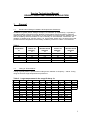
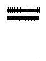
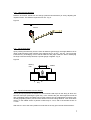
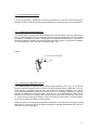
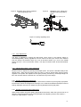
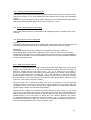
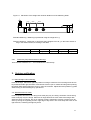
Service Technicians
Manual
GRAND PIANOS MECHANISM REGULATION
2008
1
Service Technicians Manual
GRAND PIANOS MECHANISM REGULATION
1.
General
1.1
Grand Pianos Storage Conditions at Shops and at Customers
Conditions of grand pianos storage at shops, at customers (in apartments), or possibly in
recording studios would have had be identical. Grand pianos must be located in sufficient
distance from the windows, from heaters, so that moisture occurring when the window is open
and the radiating heat from heaters do not act directly on the instrument. Instruments are
capable of fulfilling their function well in an environment where they are stored and used,
provided that the temperature and humidity conditions pursuant to Table 1 are observed:
Table 1.
Environment
temperature
°C
Minimum
relative air
humidity
%
30
31
32
34
35
10
15
20
25
30
1.2
Minimum
absolute wood
moisture
%
6,6
6,5
6.5
6.5
6.5
Maximum
relative air
humidity
%
55
56
28
60
62
Maximum
absolute wood
moisture
%
10.7
10.6
10.7
10.8
10.8
Tuning of Grand Pianos
1
Tuning of grand pianos is performed according to the chamber A frequency - 440Hz. Tuning
using the small or large temperament is performed.
Table 2. Large temperament in the range D sharp - A 1
1
1
A
11
2
A
3
1
E
3-1
4
E
4-2
5
H
5-3
14
1
F
14-1
8-14
10-8-14
15
F
15-13
15-2
15-10
15-11
12
13
D sharp
D sharp
A sharp
11-9
5-11
5-7-11
12-10
12-7
12-8
13-11
13-7
13-8
13-9
1
6
F sharp
6-2
1
7
8
F sharp
C sharp
7-5
7-3
8-6
8-2
4-2-8
18
G
18-16
18-5
12-18
1
9
G sharp
1
9-3
9-6
5-3-9
16
17
19
1
1
1
C
G
D
15-2-16 16-3-17
2-19
12-10-18 16-11-17
19-17
16-14
19-6
18-13-11 18-5-19
10-16-9
10
G sharp
10-8
10-4
10-6
15-13-19
2
Table 3. Small temperament I in the range A - A1
1
1
A
2
A
2-1
3
1
E
3-1
3-2
4
5
6
7
8
9
10
1
1
1
1
1
F F sharp C sharp G sharp D sharp A sharp F
4-3 5-1
6-2
3-7
8-7
9-8
1-10
5-2
2-6-3
6-7
8-4
6-9
9-10
6-3-7
8-4-7
5-9-6 8-10-7
4-3-7
11
12
13
1
1
1
C
G
D
10-11 11-12 12-13
2-10 11-3-10 13-2
10-3
1-13
1-10
11-10-1
Table 4. Small temperament II in the range F - E 1
1
1
A
2
A
2-1
3
4
1
D
C
3-1 5-4
3-2 5-13
5
1
C
6-5
2-6
6-13
1-6
6
7
F
A sharp
1-6
7-8
7-6
7-10
10-6 11-7-10
8
1
D sharp
8-1
8-12
8-12-1
9
10
11
12
1
1
G sharpC sharp F sharp H
13-9
10-2
11-1
2-13
10-9
2-10-13 11-2
10-13-9
12-13-9
13
1
E
13-1
13-2
3
2.
2.1
Grand Piano Mechanism Regulation (Adjustment)
Adjustment of the Key-frame-guide Adjusting Screw (balance-rail stud)
Key-frame-guide adjusting screw is adjusted using the tuning lever, without weighting the
keyboard with the action. There is a clearance between the key-bed (key-bottom) and the
key-frame-guide adjusting screw head up to 0.1 mm.
2.2
Releasing (Easing) of the Key Bottom Holes
A properly released (eased) key, upon rising ca 1 cm above the balance-rail surface and upon
its loosing, must come (slide) down the balance-pin by action of its own weight (or possibly
upon light tapping on the key), to its original position to the washer. However, at the same
time the key must not show a clearance in the hole of the key bottom on the balance pin
(visible front-back movement on the balance pin). It must be possible to lightly slide the keys
released in this manner out of the key frame pins and slide them back onto the key frame
pins. Releasing is performed using a special round reamer file for key balance holes.
2.3
Releasing (Easing) of Keys in the Key-chase (Key Button)
Between the balance pin and cashmire in the opening of the key-chase (button) of the key,
there must be clearance on every side of 0.1 mm, meaning that upon light pressing of the key
by the inner surface of the opening into the side towards the balance pin, clearance of 0.2 mm
will arise on the opposite side between the balance pin and inner wall of the opening - Fig. 1.
The clearance is checked by leaning out the key into the sides, while the key is pushed lightly
onto the balance rail using fingers of the other hand. When performing the check, the key is in
its natural (basic) position. A qualified estimate is made of the clearance required.
In case the clearance is smaller, squeezing of the opening of the key-chase (button) must be
performed for the balance pin. Releasing is performed using special squeezing key busching
pliers with parallel working jaws with a small wing. Squeezing of the openings is performed
always on both sides, so that pressing of the cashmire is uniform. Releasing must be done
carefully so that the keys are not too loose.
Figure 1 Clearance between the balance
pin and the key cashmire
Back part of the keychase (key button)
2/3
Direction of pressure
1/3
Front part of the
key-chase
approx. 0.2
4
2.4
Releasing (Easing) of Keys on the Front Pins
Between the front pin and cashmire in the key bottom opening, there must be clearance of
0.25 mm on every side; meaning that in light pressing of the key by the inner surface of the
opening into the side towards the front pin, clearance of 0.5 mm will arise on the opposite side
between the front pin and inner wall of the opening - Fig. 2.
The clearance is checked by pressing down the front part of the key on the keyboard frame
front rail so that it touch down on the felt punching of the front pin. The key is held at the place
of the key button, grabbed by the key front, and by moving the key in its front part into the
sides, the clearance of the front pin in the bottom opening of the key is checked. A qualified
estimate is made of the clearance required.
In case the clearance is smaller, pressing out (squeezing) of the opening must be performed
for the front pin. Releasing (easing) is performed using special pressing out key bushing pliers
with parallel working jaws with a small wing. Pressing out of the openings is performed always
on both sides, so that pressing of the cashmire is uniform. Releasing must be done carefully
so that the keys are not too loose. Two released adjacent keys must not touch by their
neighbouring, side surfaces ones upon their pressing towards each other. In openings for
front pins of the keys pressed out (squeezed) too much (the clearance is greater than the
tolerance prescribed), a repair is performed. Manual re-cashmiring of the opening is
performed.
Figure 2
Clearance between the oval front pin and the key cashmire
Direction of pressure
approx. 0.5
2.5
Positioning of Jacks under the Knuckles
Positioning of jacks under the knuckles is performed by the jack regulating screws. The back
side of the jack must be situated approximately by 0.5 - 0.7 mm behind the back edge of the
knuckle insert (strip), when the hammer shank is rised up ca 5 mm above the hammer
rail - Fig. 3.
Figure 3
5
2.6
Clearance of the Jack in the Repetition Lever
Clearance of the jack in the repetition lever is adjusted by the repetition-lever regulating
screw. The upper surface of the jack must be found 0.3 mm below the level of the upper
surface of the repetition lever.
2.7
Clearance between the Jack and the Jack - pad Felt
Clearance between the jack and the jack - pad felt during sliding of the jack from below the
knuckle should be 1 - 2 mm (in case of proper distance of the hammer-flange rail and wippen
rail) - Fig. 4.
Figure 4
300
Drop screw
Hammer-shank
Knuckle
Jack
2.8
Keyboard Alignment
Alignment of white keys to a level is performed by underlaying of the keys with paper washers
on the balance rail pins using a long, light, flat ruler. There must be the minimum space of
17.5 mm between the bottom surface of the key and the key frame. Distance of the upper key
surface in the front part of keys from the key bed should be the same on both sides (in the
bass as well as in discant section).
2.9
Alignment of Black Keys
Alignment of sharps to a level is performed by underlaying of the black keys with paper
washers on the balance rail pins. Distance of the upper surface of the black keys above the
white keys top surface shall be 12.3 mm.
6
2.10
Hammer-blow Distance
Distance of hammer heads from the strings (Hammer-blow distance) is set by adjusting the
capstan screws. The distance required is 45 mm - Fig. 5.
Figure 5
45
45 mm
2.11
Dip of White Keys
Upon pressing the white key onto the front rail washers (punchings), the height distance of its
upper surface and the upper surface of the adjacent key is 10 mm + 0.5 mm. The correct dip
is achieved by underlaying of front rail felt washers with paper washers. When underlaying
the keys to achieve the dip desired, a special gauge is applied - Fig. 6.
Figure 6
Moving
ruler
Leather
Key
2.12
Set-off of Hammers from the Strings
Set-off (let-off) represents the distance of the hammer head top from the string to which the
hammer rises upon pressing the given key, in the moment the jack bears against the set-off
dolly (regulating button) and slides out from the knuckle. Set-off is adjusted by turning the setoff dolly (regulating button). Set-off of the hammers from the strings shall be 3 mm in the bass
section, in the middle section it passes continuously to 2 mm, and in the discant section to
1.5 mm.
After touch 1 mm to the down position must be felt on the key upon the set-off the hammer.
7
2.13
Dip of Black Keys (Sharps)
The dip is achieved by underlaying of front rail felt washers on front rail oval pins with paper
washers so that the same feeling of the final depressing is achieved as in case of white keys.
2.14
Check (Back Check) Regulating
The checks (back checks) position and regulating is performed without using any instruments,
only by hand-bending the checks. When the checks height and position of the checks towards
the hammer mouldings are correct, the hammers are captured in the distance of 16 mm from
the strings (distance between the hammer head top and the string). The hammer mouldings
are to be captured in 1/4 to 1/3 of the check-felt length - Fig. 7.
Figure 7
1/4 - 1/3 of the check-felt length
2.15
Adjustment of Repetition Springs
The repetition spring is adjusted using a special spring regulating hook - Fig. 10. The spring
shape is adjusted, using the hook, so that it is strained (prestressed) or slackened - Fig. 9. In
some actions, a regulating screw is used, using which the springs prestress is set - Fig. 8.
The springs adjustment is checked as follows. The key is pressed completely so that the
hammer is captured by the back check. Then the key is released slightly which causes
releasing of the hammer moulding captured by the back check. This hammer then rises by ca
8 - 10 mm. When the spring prestress is correct, the hammer rises quickly in a nimble manner
but not much wildly (vehemently), without jerking.
When the spring is not strained (prestressed) sufficiently, the hammer rises sluggishly (lazily)
and slowly or it does not rise at all. When the spring is strained (prestressed) too much, the
hammer rises very vehemently.
8
Figure 8 Repetition lever with the repetitionspring-regulating-screw
Figure 9
Repetition lever without the
repetition-spring-regulatingscrew
Spring regulating hook
Figure 10 Spring regulating hook
2.16
Drop Adjustment
The drop is adjusted by turning the drop-screw. Drop screw in the hammer flange is
unscrewed partially, namely regulated in such a manner so that upon set-off of the hammer
from the strings, the hammer drops by 3 mm in the bass section, by 2 mm in the middle
section and by 1 mm in the discant section. The drop movement must be fast and definite
(exact).
2.17
Damper Run (Semi – Run) Adjustment
Damper motion is adjusted by bending the damper-spoon. The spoon is bended closely at the
damper-lever, using flat nose pliers with long jaws or using a special bent fork-type action
regulator. The spoons are adjusted so that upon pressing a white key, the damper begins to
lift in the moment when the hammer is in one half of its way to the strings.
2.18 Damper Straight Run Adjustment
Check and adjust straight uplift of dampers. When action is taken out pusch gently right pedal
several times, watch the straightness of damper´s run. Clearances between dampers must not
change, dampers must not turn. Adjust it by turning dampers wires by flat pliers.
2.19
Damper Synchronous Run Adjustment
When action is taken out pusch gently right pedal several times, watch the synchronous run of
dampers. Adjust the differences by turning damper lever adjusting screws. Late reaction –
screw out, early reaction – screw in.
9
2.20
Damper-check (Stop Rail) Adjustment
The damper-check is adjusted vertically so that the damper stroke (uplift) is sufficient, and so
that there is a space of 2 to 3 mm between the risen damper-lever and the stop rail (damper
check).
Release the screws of damper stop rail a little. Adjust stop rail vertically so that damper liftup is
sufficient and between lifted damper lever and stop rail are 2 – 3 mm.
2.21 Damper Pedal adjustment According
Adjust right pedal vertical run by adjustment of two adjusting screws in sostenuto lever under
key bed.
2.22 Prolongement function Adjustment
Function:
Push right pedal, dampers lift up. Push middle pedal, release right pedal, all the dampers must
remain lifted. Release middle pedal, all the dampers must fall down freely on strings.
Adjustment:
Push middle pedal several times, watch the prolongement brass rod. It must turn
freely without lifting up the dampers. Adjustment can be done by vertical and front-to-back
positioning of prolongement rod. Vertical positioning can be done when you release fastening
screws with cross head. Front-to-back positioning can be done by turning hexagonal fastening
screws of prolongement rod.
2.23
Balancing of the Keyboard
The key is supported with one’s finger, touching the bottom front edge of key in the normal
position. The weight (50 - 55 g, see the chart bellow) is placed onto the front edge of
white key, aligned with the front edge of key - Fig. 21. In sharp keys, the weight is
placed to be aligned with the front edge of the upper surface of the sharps. Upon releasing
the key, the key loaded with a weight (50 - 55 g, with tolerance of ±1g) and key-lead
placed at sides of the keys must overbalance barely so that the key goes down smoothly
and the hammer rises continuously up to the position when final pressure resistance is felt
on the key 1 mm from the key down position.
When the given key is balanced properly, then upon its pressing to the final pressure
resistance position 1 mm from the down position, being loaded with a 22 g weight, and upon
its releasing, the key must return up lively to its original position. The keyboard is balanced
together with the action, removed from the instrument.
Adjustment of the balance is performed by placing key-leads, of the mass 16 g into white
keys and 13 g into black keys (sharps). The balancing key-leads are located between the
balance pins and the front-rail oval pins so that the drilled-in holes centres for key-leads are
located at least 15 mm from holes for these pins. The distance between the centres
of individual balancing key-leads shall be 25 mm at least - Fig. 11. When it is necessary to
drill behind the balance pin, again, the centre of the first key-lead is located at least 15 mm
from the opening for balance pin or from the capstan screw.
10
Figure 11 Placement of the weight and minimum distances of the balancing leads
15 mm
25 mm
25 mm
Standard balancing - Balancing is performed using the weight of 51 g.
German balancing - Balancing is performed using weights from 55 g in the bass section to
50 g in the discant section, according to the table.
Keys order
Weight mass
2.24
1 - 27
55 g
28 - 40
53 g
41 - 53
52 g
54 - 67
51 g
68 - 88
50 g
Fasten Key Stop Rail back above the keys.
There must be clearance of 1 – 2 mm between the rail and keys.
3. Voicing verification
3.1 Hammer Right-Left Positioning.
Push all the keys, watch their right-left position on strings. Hammers of more-string tones have to
be positioned a little right, because of movement of action (not to contact left string when pushing
left pedal). Bass single strigs have to be in centre of hammers. Adjust hammers position by gentle
aside turning of hammer flanges by special tool.
3.2 Side Movement of Action.
Push left pedal, hammers of two string tones must play only one string. Hammers of three string
tones must play only two strings. Hammers of single bass tones must contact the string a little
aside the centre of hammer, but not on hammer´s edge. Adjustment of action movement can be
done by turning the regulating screw in right edge of key frame. This screw stops the action in the
right moment, contacting the right key block.
11
3.3 Hammer Positioning on Strings.
Check the right contact of hammers on more-string tones. Lift up the hammer shank by special
hook, push the hammer gently to strings, push right pedal (dampers up). Twang by plectrum the
strings of one tone separately, none of them can play. If some of them sounds, sand the hammer
under other strings of this tone carefully.
3.4 Voicing Verification.
Play separated sections repeatedly, look for tones with different colour of tone, mark this tone.
Stick the hammers of too sharp tone by voicing needles. Modify needling techniques according to
required tone change. For example make the first deep stitch by single needle to sides of hammer
or to it´s arms. Then make only gentle stitches to arms of hammer by single or three needle tool.
Check the tone when you press left pedal. Unify the different tones by additional needling. Then
brush the hammers by brass brush in the end.
12