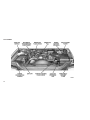
1
TABLE OF CONTENTS
1
INTRODUCTION
2
THINGS TO KNOW BEFORE STARTING YOUR VEHICLE
3
UNDERSTANDING THE FEATURES OF YOUR VEHICLE
4
UNDERSTANDING YOUR INSTRUMENT PANEL
5
STARTING AND OPERATING
6
WHAT TO DO IN EMERGENCIES
7
MAINTAINING YOUR VEHICLE
8
MAINTENANCE SCHEDULES
9
IF YOU NEED CONSUMER ASSISTANCE
10
INDEX
......................................................................3
.............................................7
. . . . . . . . . . . . . . . . . . . . . . . . . . . . . . . . . . . . . . . . . . . . . 27
. . . . . . . . . . . . . . . . . . . . . . . . . . . . . . . . . . . . . . . . . . . . . . . . . . 53
. . . . . . . . . . . . . . . . . . . . . . . . . . . . . . . . . . . . . . . . . . . . . . . . . . . . . . . . . . . . . 65
. . . . . . . . . . . . . . . . . . . . . . . . . . . . . . . . . . . . . . . . . . . . . . . . . . . . . . . . . . . 87
. . . . . . . . . . . . . . . . . . . . . . . . . . . . . . . . . . . . . . . . . . . . . . . . . . . . . . . . . . . . 93
. . . . . . . . . . . . . . . . . . . . . . . . . . . . . . . . . . . . . . . . . . . . . . . . . . . . . . . . . . . . 117
. . . . . . . . . . . . . . . . . . . . . . . . . . . . . . . . . . . . . . . . . . . . . . . . . . . . . 139
. . . . . . . . . . . . . . . . . . . . . . . . . . . . . . . . . . . . . . . . . . . . . . . . . . . . . . . . . . . . . . . . . . . . . . . . . . 149
1
2
1
INTRODUCTION
• INTRODUCTION . . . . . . . . . . . .
• Roll Over Warning . . . . . . . .
• IMPORTANT NOTICE . . . . . . . . .
• HOW TO USE THIS MANUAL . . . .
• WARNINGS AND CAUTIONS . . . .
• VEHICLE IDENTIFICATION NUMBER
.
.
.
.
.
.
.
.
.
.
.
.
.
.
.
.
.
.
.
.
.
.
.
.
.
.
.
.
.
.
.
.
.
.
.
.
.
.
.
.
.
.
.
.
.
.
.
.
.
.
.
.
.
.
.
.
.
.
.
.
.
.
.
.
.
.
.
.
.
.
.
.
.
.
.
.
.
.
.
.
.
.
.
.
.
.
.
.
.
.
4
4
5
6
6
6
3
INTRODUCTION
Roll Over Warning
Thank you for selecting one of our popular JeepT
models. Be assured that it represents precision
workmanship, distinctive styling and high quality
traditional with JeepT vehicles.
Utility vehicles have a significantly higher roll over
rate than other types of vehicles. This vehicle has
a higher ground clearance, higher center of gravity, and narrower track than many passenger cars.
It is capable of performing better in a wide variety
of off-road applications. Driven in an unsafe manner, all vehicles can be caused to go out of
control. Because of the higher center of gravity
and the narrower track, if this vehicle is out of
control it may roll over when some other vehicles
may not.
This is a specialized utility vehicle designed for
both on-road and off-road use. It can go places
and perform tasks for which conventional 2–wheel
drive vehicles were not intended. It handles and
maneuvers differently from many passenger cars
both on-road and off-road, so take time to become
familiar with your vehicle.
Before you start to drive this vehicle, read the
Owner’s Manual and all the Supplements. Be sure
you are familiar with all vehicle controls, particularly those used for braking, steering and transmission and transfer case shifting. Learn how your
vehicle handles on different road surfaces. Your
driving skills will improve with experience, but as
in driving any vehicle, take it easy as you begin.
When driving off-road or working the vehicle, don’t
overload it or expect it to overcome the forces of
nature. Always observe local laws wherever you
drive.
As with other vehicles of this type, failure to
operate this vehicle correctly may result in loss of
control or an accident. Be sure to read the “OnRoad” and “Off-Road Driving Tips” in Section 5 of
this manual.
4
Do not attempt sharp turns at high speeds or
abrupt maneuvers or other unsafe driving actions
that can cause loss of vehicle control. Failure to
operate this vehicle safely may result in an accident, roll over of the vehicle, and severe or fatal
injury. Drive carefully.
Failure to use the driver and passenger seat belts
provided as standard equipment on all vehicles is
a major cause of serious injury or death. In a roll
over crash an unbelted person is significantly
more likely to die than a person wearing a seat
belt. Always buckle up.
Operating this vehicle at excessive speeds or
while intoxicated may result in loss of control,
collision with other vehicles or objects, going off
the road, or overturning; any of which may lead to
serious injury or death. Also, failure to use the seat
belts subjects the driver and passengers to a
greater risk of injury in the event of an accident.
To keep your vehicle running at it’s best, have your
vehicle serviced at recommended intervals by an
authorized JeepT dealer or distributor who has the
qualified personnel, special tools and equipment
to perform all service. The manufacturer and its
distributors are vitally interested in your complete
satisfaction with this vehicle. If you encounter a
service or warranty problem which is not resolved
to your satisfaction, discuss the matter with your
authorized JeepT dealer or distributor’s management.
Your authorized JeepT dealer or distributor will be
happy to assist you with any questions about your
vehicle.
IMPORTANT NOTICE
ALL MATERIAL CONTAINED IN THIS PUBLICATION IS BASED ON THE LATEST INFORMATION
AVAILABLE AT TIME OF PUBLICATION APPROVAL. THE RIGHT IS RESERVED TO PUBLISH
REVISIONS AT ANY TIME.
This manual has been prepared with the assistance of service and engineering specialists to
acquaint you with the operation and maintenance
of your new vehicle. It is supplemented by a
Warranty Information Booklet and various customer oriented documents. You are urged to read
these publications carefully. Following the instructions and recommendations in this manual will
help assure safe and enjoyable operation of your
vehicle.
After you have read the manual, it should be
stored in the vehicle for convenient reference and
remain with the vehicle when sold.
The manufacturer reserves the right to make
changes in design and specifications, and/or to
make additions to or improvements in its products
without imposing any obligations upon itself to
install them on products previously manufactured.
The Owner’s Manual illustrates and describes the
features that are standard or available as extra
cost options. Therefore, some of the equipment
and accessories in this publication may not appear on your vehicle.
NOTE:
Be sure to read the Owner’s Manual first before
driving your vehicle and before attaching or
installing parts/accessories or making other
modifications to the vehicle.
In view of the many replacement parts and accessories from various manufacturers available on
the market, the manufacturer cannot be certain
that the driving safety of your vehicle will not be
impaired by the attachment or installation of such
parts. Even if such parts are officially approved
(for example, by a general operating permit for the
part or by constructing the part in an officially
approved design), or if an individual operating
permit was issued for the vehicle after the attachment or installation of such parts, it cannot be
implicitly assumed that the driving safety of your
vehicle is unimpaired. Therefore, neither experts
nor official agencies are liable. The manufacturer
only assumes responsibility therefore when parts
which are expressly authorized or recommended
by the manufacturer are attached or installed at
an authorized dealer. The same applies when
modifications to the original condition are subsequently made on the manufacturers vehicles.
Your warranties do not cover any part that the
manufacturer did not supply. Nor do they cover
the cost of any repairs or adjustments that might
be caused or needed because of the installation
or use of non-manufacturer parts, components,
equipment, materials or additives. Nor do your
warranties cover the costs of repairing damage or
conditions caused by any changes to your car
that do not comply with the manufacturers specifications.
Original Mopar parts and accessories and other
products approved by the manufacturer, including qualified advice, are available at your authorized dealer.
When it comes to service, remember that your
dealer knows your vehicle best, has the factorytrained technicians and genuine Mopar parts and
is interested in your satisfaction.
Copyright © 2002 Chrysler
5
HOW TO USE THIS MANUAL
WARNINGS AND CAUTIONS
VEHICLE IDENTIFICATION NUMBER
Consult the table of contents to determine which
section contains the information you desire.
This manual contains WARNINGS against operating procedures which could result in an accident or bodily injury. It also contains CAUTIONS
against procedures which could result in damage
to your vehicle. If you do not read this entire
manual you may miss important information. Observe all Warnings and Cautions.
The vehicle identification number (VIN) is found
on a stamped plate located on the left front corner
of the instrument panel pad, visible from outside
of the vehicle through the windshield.
The detailed index, at the rear of the manual,
contains a complete listing of all subjects.
NOTE:
Do not tamper with the VIN plate.
6
2
THINGS TO KNOW BEFORE STARTING
YOUR VEHICLE
• A WORD ABOUT YOUR KEYS . . . . . . . .
• Ignition Key . . . . . . . . . . . . . . . . .
• Key-In-Ignition Reminder . . . . . . . . .
• SENTRY KEY IMMOBILIZER SYSTEM . . . .
• General Information . . . . . . . . . . . .
• ILLUMINATED ENTRY . . . . . . . . . . . . .
• DOOR AND LIFTGATE LOCKS . . . . . . . .
• Liftgate Flipper Glass . . . . . . . . . . .
• Door Locks . . . . . . . . . . . . . . . . . .
• Power Door Lock System . . . . . . . . .
• REMOTE KEYLESS ENTRY . . . . . . . . . .
• To Unlock the Doors and Liftgate . . . .
• To Lock the Doors and Liftgate . . . . . .
• General Information . . . . . . . . . . . .
• Programming Additional Transmitters . .
• Transmitter Battery Replacement . . . . .
• SECURITY ALARM SYSTEM — IF EQUIPPED
• To Set the Alarm . . . . . . . . . . . . . .
.
.
.
.
.
.
.
.
.
.
.
.
.
.
.
.
.
.
.
.
.
.
.
.
.
.
.
.
.
.
.
.
.
. .
.
.
.
.
.
.
.
.
.
.
.
.
.
.
.
.
.
.
.
.
.
.
.
.
.
.
.
.
.
.
.
.
.
.
.
.
.
.
.
.
.
.
.
.
.
.
.
.
.
.
.
.
.
.
.
.
.
.
.
.
.
.
.
.
.
.
.
.
.
.
.
.
.
.
.
.
.
.
.
.
.
.
.
.
.
.
.
.
.
.
.
.
.
.
.
.
.
.
.
.
.
.
.
.
.
.
.
.
.
.
.
.
.
.
.
.
.
.
.
.
.
.
.
.
.
.
.
.
.
.
9
9
9
9
10
10
10
10
11
11
12
12
12
12
12
12
13
13
7
• To Disarm the System . . . . . . . . . . . . . . . . . .
• POWER WINDOWS . . . . . . . . . . . . . . . . . . . . . .
• Wind Buffeting . . . . . . . . . . . . . . . . . . . . . . .
• OCCUPANT RESTRAINTS . . . . . . . . . . . . . . . . . .
• Lap/Shoulder Belts . . . . . . . . . . . . . . . . . . . .
• Lap/Shoulder Belt Operating Instructions . . . . . . .
• Adjustable Upper Shoulder Belt Anchorage . . . . .
• Automatic Locking Mode — If Equipped . . . . . . .
• Energy Management Feature . . . . . . . . . . . . . .
• Seat Belts and Pregnant Women . . . . . . . . . . . .
• Driver And Front Passenger Supplemental Restraint
Systems (SRS) — Airbags . . . . . . . . . . . . . . . .
• Child Restraint . . . . . . . . . . . . . . . . . . . . . .
• ENGINE BREAK-IN RECOMMENDATIONS . . . . . . . . .
• SAFETY TIPS . . . . . . . . . . . . . . . . . . . . . . . . .
• Exhaust Gas . . . . . . . . . . . . . . . . . . . . . . . .
• Safety Checks You Should Make Inside The Vehicle
• Safety Checks You Should Make Outside The Vehicle
8
.
.
.
.
.
.
.
.
.
.
.
.
.
.
.
.
.
.
.
.
13
14
14
15
15
15
17
17
17
18
.
.
.
.
.
.
.
.
.
.
.
.
.
18
22
24
25
25
25
25
A WORD ABOUT YOUR KEYS
Key-In-Ignition Reminder
The keys for your new vehicle are enclosed in a
plastic bag with the key code number on it. If you
received your keys without the bag, ask your
authorized dealer to give you the number. The key
code can also be obtained by your authorized
dealer from your vehicle invoice.
If the driver’s door is opened when the key is in the
ignition and not turned to the ON position, a chime
will sound to remind you to remove the key.
Ignition Key
Insert the key fully, then turn the switch to one of
the four illustrated positions. The key can be
inserted or withdrawn only in the LOCK position.
The gearshift lever must be in the P (Park) position.
To remove the ignition key, place the gearshift
lever in P (Park), turn the ignition key to LOCK and
remove the key.
CAUTION!
Always remove the key from the ignition, and
lock all doors when leaving the vehicle unattended.
SENTRY KEY IMMOBILIZER SYSTEM
The Sentry Key Immobilizer System (SKIS) prevents unauthorized operation of the vehicle by
disabling the engine. The system will shut the
engine down after 2 seconds of running if an
invalid key is used to start the vehicle. This system
utilizes ignition keys which have an electronic chip
(transponder) embedded into them. Only keys
that have been programmed to the vehicle can be
used to start and operate the vehicle for longer
than the 2 second validation time period.
The Sentry Key Immobilizer System does not
need to be armed or activated. Operation of the
system is automatic regardless of whether or not
the vehicle is locked or unlocked. During normal
operation, the SKIS indicator light will come on for
3 seconds immediately after the ignition switch is
turned on for a bulb check. Afterwards, if the bulb
remains on, this indicates a malfunction in the
electronics. If the bulb begins to flash immediately
after the ignition switch has been turned on, this
indicates that an invalid key has been used to
start the vehicle. Both of these conditions will
result in the engine being shut down after 2
seconds of running. Keep in mind that a key which
has not been programmed is also considered an
invalid key even if it is cut to fit the ignition for that
vehicle.
If the SKIS indicator light comes on during normal
vehicle operation (it has been running for longer
than 10 seconds) a fault has been detected in the
electronics. If this occurs, DO NOT TURN THE
IGNITION OFF since this failure will result in the
vehicle being shut down on each subsequent
ignition cycle. Take the vehicle directly to your
authorized dealer for service.
NOTE:
A four digit PIN is needed to service the Sentry
Key Immobilizer System. This number can be
obtained by your authorized dealer.YOU MUST
BRING ALL SENTRY KEYS that are programmed to your vehicle with you when bringing your vehicle in for service.
9
General Information
ILLUMINATED ENTRY
Hereby, Siemens AG, Automotive Systems Group,
Access Control and Security Systems, declares
that the Sentry Key Immobilizer is in compliance
with the essential requirements and other relevant
provisions of Directive 1999/5/EC.
The interior lights come on when you open any
door. They will remain on for about 30 seconds
after all doors are closed then fade to off.
The Sentry Key Immobilizer is a 134 kHz system.
It will be used in the following European countries,
which apply Directive 1999/5/EC: Austria, Belgium, Czech Republic, Denmark, Finland, France,
Germany, Greece, Hungary, Ireland, Italy, Luxembourg, Netherlands, Norway, Poland, Portugal,
Romania, Russian Federation, Slovenia, Spain,
Sweden, Switzerland, Yugoslavia, and United
Kingdom.
To view the original Declaration of Conformity, visit
http://www.siemensauto.com/glossaries/
skim_ec.html on the Internet.
Operation is subject to the following two conditions:
1. This device may not cause harmful interference.
2. This device must accept any interference that
may be received, including interference that may
cause undesired operation.
10
The lights also will fade to off if you turn on the
ignition after you close all the doors.
DOOR AND LIFTGATE LOCKS
NOTE:
The master key that is used to start the vehicle
is used to lock or unlock the driver’s door. To
unlock the driver’s door insert the key into the
lock and turn.
interrupted, preventing activation of the rear wiper
blade while the flipper glass is open.
NOTE:
If a power malfunction to the power liftgate
latch should occur, an emergency liftgate latch
release can be used to open the liftgate. The
emergency liftgate latch release can be accessed through a snap-in cover located on the
liftgate trim panel.
To open the liftgate, pull out on the handle and lift.
WARNING!
Driving with the liftgate open can allow poisonous exhaust gases into your vehicle. You and
your passengers could be injured by these
fumes. Keep the liftgate closed when you are
operating the vehicle.
WARNING!
Liftgate Flipper Glass
The liftgate flipper glass is also unlocked when the
liftgate is unlocked. To open the flipper glass,
push up on the window switch located on the
liftgate. Once the liftgate flipper glass has been
opened, connection to the rear window wiper is
Driving with the flipper glass open can allow
poisonous exhaust gases into your vehicle. You
and your passengers could be injured by these
fumes. Keep the flipper glass closed when you
are operating the vehicle.
Door Locks
All doors are equipped with a slide-type interior
door lock. To manually lock a door, slide the lever
rearward (toward the rear of the vehicle) to the
“Lock” position.
Once locked, the rear doors cannot be opened
from the inside until the lock lever has been
released. However, the front doors can be opened
using the inside door handle.
WARNING!
Avoid trapping anyone in the vehicle in a collision. Remember that the rear doors can only be
opened from the outside when the child protection locks are engaged.
To manually unlock a door, slide the lever forward
(toward the front of the vehicle) to the “Unlock”
position.
Once locked, the rear doors cannot be opened
from the inside until the lock lever has been
released. However, both front doors can be
opened using the inside door handle.
WARNING!
For personal security reasons and safety in a
collision, lock the vehicle doors when you drive
and when you park and leave the vehicle.
Child Protection Locks
The rear doors of your vehicle are equipped with
child protection locks. If you push up on the lever
on the open edge of the door it cannot be opened
from the inside of the vehicle. Push the lever down
to disengage the child protection locks.
Power Door Lock System
The power door locks are on a paddle-type
switch. Pressing the switch toward the rear of the
vehicle will “Lock” all doors. Pressing the switch
toward the front of the vehicle will “Unlock” all
doors. The driver’s and passenger’s switch locks
and unlocks all doors and the liftgate.
Automatic Door Locks
If this feature is selected your door locks will lock
automatically if the vehicle speed is above 24
km/h (15 mph) and all doors are closed. It will
reset whenever a door is opened.
This feature is selectable and can be turned on or
off. Refer to “Overhead Console — Customer
Programmable Features” in Section 3 of this
manual or see your authorized dealer.
As a safety feature, the power door lock switch will
not lock when the door is open and the key is in
the ignition.
11
Automatic Unlock on Exit Feature — Only
Available if Auto Lock is Enabled
This feature will unlock all the doors when the
driver’s door is opened if the vehicle is stopped
and in P (Park) or N (Neutral). Refer to “Overhead
Console — Customer Programmable Features” in
Section 3 of this manual or see your authorized
dealer.
unlock all doors and liftgate. The illuminated entry
system will also come on.
REMOTE KEYLESS ENTRY
• On vehicles equipped with an overhead console these functions can be selected at the
overhead console using the “Customer Programmable Features.” Refer to “Customer Programmable Features” in the Overhead Console
section, otherwise see your authorized dealer.
NOTE:
The system can be programmed to do the
following:
• unlock all the doors on the first button press
• flash the turn signals twice with unlock
To Lock the Doors and Liftgate
This system allows you to lock or unlock the doors
and liftgate from distances up to about 7 meters
(23 feet) using a hand held radio transmitter. The
transmitter need not be pointed at the vehicle to
activate the system.
To Unlock the Doors and Liftgate
Press and release the “Unlock” button on the key
fob once to unlock the driver’s door, or twice to
12
Press and release the “Lock” button on the key
fob to lock all doors and liftgate. If you wish, the
turn signals can be programmed to flash once to
show the system is activated. For customer programmable features refer to the section on “Overhead Console” for programming details, otherwise see your authorized dealer.
General Information
Hereby, TRW Automotive, Electronics Group, declares that the Remote Keyless Entry is in compliance with the essential requirements and other
relevant provisions of Directive 1999/5/EC.
The Remote Keyless Entry is a 433.92 Mhz system. It will be used in the following European
countries, which apply Directive 1999/5/EC: Austria, Belgium, Czech Republic, Denmark, Finland,
France, Germany, Greece, Hungary, Ireland, Italy,
Luxembourg, Netherlands, Norway, Poland, Portugal, Romania, Russian Federation, Slovenia,
Spain, Sweden, Switzerland, Yugoslavia, and
United Kingdom.
Operation is subject to the following two conditions:
1. This device may not cause harmful interference.
2. This device must accept any interference that
may be received, including interference that may
cause undesired operation.
Programming Additional Transmitters
Up to four transmitters can be programmed. See
your authorized dealer.
Transmitter Battery Replacement
The recommended replacement battery is a Panasonic CR2016 or equivalent.
NOTE:
Do not touch the battery terminals that are on
the back housing or the printed circuit board.
1. With the transmitter buttons facing down, use a
thin coin to pry the two halves of the transmitter
apart. Make sure not to damage the rubber gasket
during removal.
2. Remove and replace the batteries. Avoid
touching the new batteries with your fingers. Skin
oils may cause battery deterioration. If you touch
a battery, clean it with rubbing alcohol.
3. To reassemble the transmitter case snap two
halves together. Make sure there is an even “gap”
between the two halves.
4. Reset the transmitter by pressing the unlock
button six times. Test the transmitter operation.
SECURITY ALARM SYSTEM — IF
EQUIPPED
The vehicle security alarm system is available in a
base or premium version. Both versions of these
systems monitors the vehicle doors, liftgate, liftgate flipper glass, hood, and ignition status for
unauthorized operation. In addition, the premium
system monitors motion inside of the vehicle.
When the alarm is activated, the system provides
both audible and visual signals. In the base
version, the horn and exterior lights will pulse for
25 seconds. In the premium version, the exterior
lights and siren will pulse for 25 seconds. If
disturbance is still present, the siren will pulse for
another 25 seconds. This will continue for a maximum of 10 cycles.
To Set the Alarm
The alarm will set when you use the remote
keyless entry transmitter to lock the doors and
liftgate or when you use the power door lock
switch while the door is open. After all the doors
are locked and closed, a red light on the instrument panel will flash rapidly for about 16 seconds
to signal that the system is arming. During this 16
second arming period, opening any door, the
liftgate, or hood will cancel the arming. If the
system successfully arms, the red light will flash at
a slower rate to indicate the alarm is set. If the
hood is left open during arming, the hood will be
ignored as an input until closed. The motion
detect feature (premium model only) can be disabled by pressing the “Lock” button on the transmitter 3 times within 16 seconds during system
arming. The system will provide a single siren
“chirp” as an audible confirmation of motion disable.
To Disarm the System
To disarm the system, use the remote keyless
entry transmitter to unlock the door’s. If something
has triggered the system in your absence, the
horn (base model only) or siren (premium model
only) will sound three times when you unlock the
doors. Check the vehicle for tampering.
The Security Alarm System is designed to protect
your vehicle; however, you can create conditions
where the system will alarm unexpectedly. If the
system is armed and you unlock the driver’s door,
passenger door, or liftgate using a key and then
open it, or if you remain in the vehicle and lock the
doors with the transmitter the system will arm. The
alarm will then sound when you pull the door
handle to exit or if you move inside the vehicle
(premium model only). If this occurs, press the
“Unlock” button on the remote keyless entry transmitter to disarm the system. If the key is used to
lock the vehicle, the door will be locked but the
Security Alarm will not arm.
13
NOTE:
In order to avoid false alarms (premium model
only), keep all windows and sunroof (if
equipped) closed while the system is armed.
POWER WINDOWS
An individual lever-type switch controls each side
window. Push the lever down to lower a window
and push the lever up to raise it. Window controls
on the driver’s door control all door windows. A
lockout control allows only the driver to operate
the windows.
14
WARNING!
Never leave children in a vehicle, with the keys
in the ignition switch. Occupants, particularly
unattended children can become entrapped by
the windows while operating the power window
switches. Such entrapment may result in serious injury or death.
NOTE:
The electrical power windows are protected by
an overload circuit breaker. This circuit
breaker will reset itself automatically. However,
in an emergency situation, it might require a
few seconds of not operating the window
switch, in the up or down position, before the
windows will be able to operate.
The driver’s window switch has an “Auto Down”
feature. Press the window switch past the detent,
release, and the window will go down automatically.
NOTE:
A small light in each passenger’s window
switch turns on and off with the lockout switch
showing if the windows are enabled or disabled.
Wind Buffeting
The power window switches remain active for up
to 45 seconds after the ignition key has been
turned OFF. Opening a vehicle front door will
cancel this feature.
Wind buffeting can be described as the perception of pressure on the ears or a helicopter type
sound in the ears. Your vehicle may exhibit wind
buffeting with the windows down, or the sunroof (if
so equipped) in certain open or partially open
positions. This is a normal occurrence and can be
minimized. If the buffeting occurs with the sunroof
open, adjust the sunroof opening to minimize the
buffeting.
OCCUPANT RESTRAINTS
Some of the most important safety features in your
vehicle are the restraint systems. These include
the front and rear seat belts for the driver and all
passengers, and front airbags for both the driver
and right front passenger. If you will be carrying
children too small for adult-size belts, your seat
belts also can be used to hold infant and child
restraint systems.
NOTE:
The front airbags have a multi stage inflator
design. This allows the airbag to have different
rates of inflation that are based on collision
severity.
Please pay close attention to the information in
this section. It tells you how to use your restraint
system properly to keep you and your passengers
as safe as possible.
WARNING!
In a collision, you and your passengers can
suffer injuries, including fatalities, if you are not
properly buckled up. You can strike the interior
of your vehicle or other passengers, or you can
be thrown out of the vehicle. Always be sure you
and others in your vehicle are buckled up properly.
Buckle up even though you are an excellent
driver, even on short trips. Someone on the road
may be a poor driver and cause a collision which
includes you. This can happen far away from
home or on your own street.
Research has shown that seat belts save lives,
and they can reduce the seriousness of injuries in
a collision. Some of the worst injuries happen
when people are thrown from the vehicle. Seat
belts reduce the possibility of ejection and the risk
of injury caused by striking the inside of the
vehicle. Everyone in a motor vehicle should be
belted at all times to reduce or prevent injuries.
Lap/Shoulder Belts
The front and rear seats of your vehicle have
combination lap/shoulder belts.
The belt webbing retractor is designed to lock
during very sudden stops or collisions. This feature allows the shoulder part of the belt to move
freely with you under normal conditions. But in a
collision, the belt will lock and reduce the risk of
you striking the inside of the vehicle or being
thrown out.
WARNING!
• Wearing a seat belt incorrectly is dangerous.
Seat belts are designed to go around the
large bones of your body. These are the
strongest parts of your body and can take the
forces of a collision the best. Wearing your
belt in the wrong place could make your
injuries in a collision much worse. You might
suffer internal injuries, or you could even slide
out of part of the belt. Follow these instructions to wear your seat belt safely and to keep
your passengers safe, too.
• Two people should never be belted into a
single seat belt. People belted together can
crash into one another in an accident, hurting
one another badly. Never use a lap/shoulder
belt or a lap belt for more than one person, no
matter what their size.
Lap/Shoulder Belt Operating
Instructions
1. Enter the vehicle and close the door. Sit back
and adjust the seat.
15
2. The seat belt latch plate is above the back of
your seat. Grasp the latch plate and pull out the
belt. Slide the latch plate up the webbing as far as
necessary to make the belt go around your lap.
WARNING!
A belt that is buckled into the wrong buckle will
not protect you properly. The lap portion could
ride too high on your body, possibly causing
internal injuries. Always buckle your belt into the
buckle nearest you.
A belt that is too loose will not protect you as
well. In a sudden stop you could move too far
forward, increasing the possibility of injury. Wear
your seat belt snugly.
3. When the belt is long enough to fit, insert the
latch plate into the buckle until you hear a “click.”
A belt that is worn under your arm is very
dangerous. Your body could strike the inside
surfaces of the vehicle in a collision, increasing
head and neck injury. A belt worn under the arm
can cause internal injuries. Ribs aren’t as strong
as shoulder bones. Wear the belt over your
shoulder so that your strongest bones will take
the force in a collision.
A shoulder belt placed behind will not protect
you from injury during a collision. You are more
likely to hit your head in a collision if you do not
wear your shoulder belt. The lap and shoulder
belt are meant to be used together.
16
4. Position the lap belt across your thighs, below
your abdomen. To remove slack in the lap portion,
pull up a bit on the shoulder belt. To loosen the lap
belt if it is too tight, tilt the latch plate and pull on
the lap belt. A snug belt reduces the risk of sliding
under the belt in a collision.
WARNING!
A lap belt worn too high can increase the risk of
injury in a collision. The belt forces won’t be at
the strong hip and pelvic bones, but across your
abdomen. Always wear the lap part of your seat
belt as low as possible and keep it snug.
A twisted belt can’t do its job as well. In a
collision it could even cut into you. Be sure the
belt is straight. If you can’t straighten a belt in
your vehicle, take it to your authorized dealer
and have it fixed.
5. Position the shoulder belt on your chest so that
it is comfortable and not resting on your neck. The
retractor will withdraw any slack in the belt.
Adjustable Upper Shoulder Belt
Anchorage
In the front seat positions, the shoulder belt can
be adjusted upward or downward to position the
belt away from your neck. Press on the release
button to release the anchorage, and then move it
up or down to the position that serves you best.
When To Use The Automatic Locking Mode
Anytime a child safety seat is installed in a passenger front seating position. Children 12 years
old and under should be properly restrained in the
rear seat whenever possible.
How To Use The Automatic Locking Mode
1. Buckle the combination lap and shoulder belt.
2. Grasp the shoulder portion and pull downward
until the entire belt is extracted.
3. Allow the belt to retract. As the belt retracts,
you will hear a clicking sound. This indicates the
safety belt is now in the automatic locking mode.
6. To release the belt, push the red button marked
PRESS on the buckle. The belt will automatically
retract to its stowed position. If necessary, slide
the latch plate down the webbing to allow it to
retract fully.
WARNING!
A frayed or torn belt could rip apart in a collision
and leave you with no protection. Inspect the
belt system periodically, checking for cuts, frays,
or loose parts. Damaged parts must be replaced
immediately. Do not disassemble or modify the
system. Seat belt assemblies must be replaced
after an accident if they have been damaged
(bent retractor, torn webbing, etc.).
As a guide, if you are shorter than average, you
will prefer a lower position, and if you are taller
than average, you’ll prefer a higher position. When
you release the anchorage, try to move it up or
down to make sure that it is locked in position.
Automatic Locking Mode — If
Equipped
In this mode, the shoulder belt is automatically
pre-locked. The belt will still retract to remove any
slack in the shoulder belt.
How to Disengage The Automatic Locking
Mode
Disconnect the combination lap/shoulder belt and
allow it to retract completely to disengage the
automatic locking mode and activate the vehicle
sensitive (emergency) locking mode.
Energy Management Feature
This vehicle has a safety belt system with an
energy management feature in the front seating
positions to help further reduce the risk of injury in
the event of a head-on collision.
This safety belt system has a retractor assembly that
is designed to pay out webbing in a controlled
manner. This feature is designed to help reduce the
belt force acting on the occupant’s chest.
17
WARNING!
• After a vehicle collision, the front passenger
outboard seat belt system must be checked
by a qualified technician to verify that the
“automatic locking retractor” feature for child
seats is still functioning properly. In addition,
all seat belts should be checked for proper
function.
come across the abdomen. That way the strong
bones of the hips will take the force if there is a
collision.
NOTE:
The front airbags are certified to the regulations that allow less forceful deployment.
Driver And Front Passenger
Supplemental Restraint Systems
(SRS) — Airbags
The front airbags have a multi stage inflator design. This allows the airbag to have different rates
of inflation that are based on collision severity.
This vehicle is equipped with window bags to
protect the driver, front, and rear passengers
sitting next to a window. The window bags are
located above the side windows.
• The belt and retractor assembly must be
replaced if the seat belt assembly “automatic
locking retractor” feature or any other seat
belt function is not working properly when
checked according to the procedures in the
Service Manual.
• Failure to replace the belt and retractor assembly could increase the risk of injury in
collisions.
Seat Belts and Pregnant Women
We recommend that pregnant women use the
seat belts throughout their pregnancy. Keeping
the mother safe is the best way to keep the baby
safe.
Pregnant women should wear the lap part of the
belt across the thighs and as snug across the hips
as possible. Keep the belt low so that it does not
18
This vehicle has airbags for both the driver and
right front passenger as a supplement to the seat
belt restraint systems. The driver’s front airbag is
mounted in the steering wheel. The passenger
side airbag is mounted in the instrument panel,
above the glove compartment. The words SRS/
AIRBAG are embossed on the airbag covers.
NOTE:
Airbag covers may not be obvious in the interior trim; but they will open to allow airbag
deployment.
WARNING!
• Do not put anything on or around the front
airbag covers or attempt to manually open
them. You may damage the airbags and you
could be injured because the airbags are not
there to protect you. These protective covers
for the airbag cushions are designed to open
only when the airbags are inflating.
• Do not stack luggage or other cargo up high
enough to block the location of the window
bag. The area where the window bag is
located should remain free from any obstructions.
• Do not have any accessory items installed
which will alter the roof, including adding a
sunroof to your vehicle. Do not add roof racks
that require permanent attachments (bolts or
screws) for installation on the vehicle roof. Do
not drill into the roof of the vehicle for any
reason.
• Do not cover or place items on the airbag
covers. These items may cause serious injury
during inflation.
The front airbags have a multi stage inflator design. This allows the airbag to have different rates
of inflation that are based on collision severity.
Along with the seat belts, front airbags work with
the instrument panel knee bolsters to provide
improved protection for the driver and front passenger. Window bags also work with seat belts to
improve occupant protection.
The seat belts are designed to protect you in
many types of collisions. The front airbags deploy
in moderate to severe frontal collisions. But even
in collisions where the airbags work, you need the
seat belts to keep you in the right position for the
airbags to protect you properly.
Here are some simple steps you can take to
minimize the risk of harm from a deploying airbag.
1. Children 12 years and under should always
ride buckled up in a rear seat.
Infants in rear-facing child restraints should
NEVER ride in the front seat of a vehicle with a
passenger front airbag. An airbag deployment
can cause severe injury or death to infants in that
position.
If a child from 1 to 12 years old must ride in the
front passenger seat because the vehicle is
crowded, move the seat as far back as possible,
and use the proper child restraint. See “Child
Restraint” in this section.
You should read the instructions provided with
your child restraint belt-positioning booster seat to
make sure that you are using it properly.
2. All occupants should use their lap and shoulder belts properly.
3. The driver and front passenger seats should
be moved back as far as practical to allow the
airbag room to inflate.
4. Do not lean against the door or window, airbags will inflate forcefully into the space between
you and the door.
WARNING!
• Relying on the airbags alone could lead to
more severe injuries in a collision. The airbags work with your seat belt to restrain you
properly. In some collisions the airbags won’t
deploy at all. Always wear your seat belts
even though you have airbags.
• Being too close to the steering wheel or
instrument panel during airbag deployment
could cause serious injury. Airbags need
room to inflate. Sit back, comfortably extending your arms to reach the steering wheel or
instrument panel.
• Window bags need room to inflate. Do not
lean against the door or window. Sit upright in
the center of the seat.
19
Airbag System Components
The airbag system consists of the following:
• Airbag Control Module (ACM)
• Airbag Warning Light
• Driver Airbag
• Passenger Airbag
• Window Bags above Side Windows
• Steering Wheel and Column
• Instrument Panel
• Crash Sensor
• Interconnecting Wiring
• Knee Impact Bolsters
How The Airbag System Works
• The Airbag Control Module (ACM) determines
if a frontal collision is severe enough to require
the airbags to inflate. Based on the level of
collision severity, the front control module determines the proper rate of inflation. The front
airbag inflators are designed to provide different rates of airbag inflation.
• The ACM, along with the remote side impact
sensors detects side impact.
• The ACM will not detect roll over, or rear impacts.
20
• The ACM monitors the readiness of the electronic parts of the system whenever the ignition
switch is in the START or ON positions. These
include all of the items listed above except the
steering wheel and column and the knee bolsters. If the key is in the OFF position, in the
ACC position, or not in the ignition, the airbags
are not on and will not inflate.
Also, the ACM turns on the AIRBAG warning
light in the instrument panel for 6 to 8 seconds
when the ignition is first turned on, then turns
the light off. If it detects a malfunction in any
part of the system, it turns on the light either
momentarily or continuously.
WARNING!
Ignoring the AIRBAG warning light in your instrument panel could mean you won’t have the
airbags to protect you in a collision. If the light
does not come on, stays on after you start the
vehicle, or if it comes on as you drive, have the
airbag system checked right away.
• The Driver and Passenger Airbag/Inflator
Units are located in the center of the steering
wheel and the right side of the instrument
panel. When the ACM detects a collision requiring the airbags, it signals the inflator units. A
large quantity of nontoxic gas is generated to
inflate the front airbags. Different airbag inflation rates are possible based on collision severity. These rates are determined by the front
airbag control module based on collision severity. The steering wheel hub trim cover and the
upper right side of the instrument panel separate and fold out of the way as the bags inflate
to their full size. The bags fully inflate in about
50–70 milliseconds. This is about half of the
time it takes to blink your eyes. The bags then
quickly deflate while helping to restrain the
driver and front passenger.
The driver front airbag gas is vented through
the airbag material towards the instrument
panel. The passenger front airbag gas is
vented through the airbag material on the sides
of the airbag. In this way, the airbags do not
interfere with your control of the vehicle.
• The Knee Impact Bolsters help protect the
knees of the driver and the front passenger’s,
and position everyone for the best interaction
with the front airbag.
If A Deployment Occurs
The airbag system is designed to deploy the
airbags when the impact sensors detect a
moderate-to-severe frontal collision, to help restrain the driver and front passenger, and then
immediately deflate.
NOTE:
A frontal collision that is not severe enough to
need airbag protection will not activate the
system. This does not mean something is
wrong with the airbag system.
If you do have a collision which deploys the
airbags, any or all of the following may occur:
• The nylon airbag material may sometimes
cause abrasions and/or skin reddening to the
driver and front passenger as the airbags deploy and unfold. The abrasions are similar to
friction rope burns or those you might get
sliding along a carpet or gymnasium floor. They
are not caused by contact with chemicals. They
are not permanent and normally heal quickly.
However, if you haven’t healed significantly
within a few days, or if you have any blistering,
see your doctor immediately.
• As the airbags deflate you may see some
smoke-like particles. The particles are a normal
by-product of the process that generates the
nontoxic gas used for airbag inflation. These
airborne particles may irritate the skin, eyes,
nose, or throat. If you have skin or eye irritation,
rinse the area with cool water. For nose or throat
irritation, move to fresh air. If the irritation continues, see your doctor. If these particles settle
on your clothing, follow the garment manufacturer’s instructions for cleaning.
• It is not advisable to drive your vehicle after the
airbags have deployed. If you are involved in
another collision, the airbags will not be in
place to protect you.
WARNING!
Deployed airbags can’t protect you in another
collision. Have the airbags replaced by an authorized dealer as soon as possible.
The side impact SRS airbags are designed to
activate only in certain side collisions. When the
ACM in conjunction with remote side impact sensors detects a side impact collision requiring the
window bags to inflate, it signals the inflators on
the crash side of the vehicle. A quantity of nontoxic gas is generated to inflate the window bag.
The inflating window bag pushes the outside
edge of the headliner out of the way and covers
the window. The airbag inflates in about 30 milliseconds (about one quarter of the time it takes to
blink your eyes) with enough force to injure you if
you are not belted and seated properly, or if items
are positioned in the area where the window bag
inflates. This especially applies to children. The
window bag is only about 9 cm (31⁄2 inches) thick
when it is inflated.
Maintaining Your Airbag System
WARNING!
• Modifications to any part of the airbag system
could cause it to fail when you need it. You
could be injured if the airbag system is not
there to protect you. Do not modify the components or wiring, including adding any kind
of badges or stickers to the steering wheel
hub trim cover or the upper right side of the
instrument panel. Do not modify the front
bumper or vehicle body structure.
• You need proper knee impact protection in a
collision. Do not mount or locate any aftermarket equipment on or behind the knee
bolsters.
• It is dangerous to try to repair any part of the
airbag system yourself. Be sure to tell anyone
who works on your vehicle that it has an
airbag system.
21
Airbag Warning Light
You will want to have the airbag system ready to
inflate for your protection in an impact. The airbag
system is designed to be maintenance free. If any
of the following occurs, have an authorized dealer
service the system promptly:
• Does not come on during the 6 to 8 seconds
after the ignition switch is first turned on.
• Remains on after the 6 to 8 second interval.
WARNING!
In a collision, an unrestrained child, even a tiny
baby, can become a missile inside the vehicle.
The force required to hold even an infant on
your lap can become so great that you could not
hold the child, no matter how strong you are.
The child and others could be badly injured. Any
child riding in your vehicle should be in a proper
restraint for the child’s size.
• Comes on for any period of time while driving.
Child Restraint
Everyone in your vehicle needs to be buckled up
all the time — babies and children, too.
WARNING!
“Extreme Hazard! Do not use a rearward facing
child restraint on a seat protected by an airbag
in front of it!” Refer to visor mounted labels for
information.
Mass Group
0 - Up to 10 kg
(0-9 months)
0+ - Up to 13 kg
(0-2 years)
1 - 9 to 18 kg (9
months - 4
years)
II & III - 15 to
36 kg (4 - 12
years)
Seating Position
Front
Rear
Rear
PassenOutboard Center
ger
X
U
U
X
U
U
X
U
U
X
U
U
Key of letters used in the table above:
U = Suitable for “universal” category restraints
approved for use in this age/weight group.
22
UF = Suitable for forward-facing “universal” category restraints approved for use in this age/
weight group.
L = Suitable for particular child restraints given on
attached list. These restraints may be of the
“specific vehicle”, “restricted” or “semi-universal”
categories.
B = Built-in restraint approved for the age/weight
group.
X = Seat position not suitable for children in this
age/weight group.
Infants and Small Children
There are different sizes and types of restraints for
children from newborn size to the child almost
large enough for the adult seat belt. Always check
the child seat owner’s manual to ensure you have
the right seat for your child. Use the restraint that
is correct for your child:
• The rearward-facing infant restraint is for babies weighing up to about 9 kg. (20 lbs.), and
less than one year old. The infant restraint must
NEVER be used in the front seat of a vehicle
with a passenger side airbag. An airbag deployment could cause severe injury or death to
infants in this position. The infant restraint is
held in the vehicle by the lap belt or lap/
shoulder belt.
• Children under one year of age should continue
to ride in a rear-facing infant seat, even if they
weigh more than 9 kg. (20 lbs.). A “convertible”
child seat, one that is designed to be used
either rearward-facing or forward-facing,
should be used for children who are too heavy
for the infant carrier, but who are too young to
face forward in the vehicle.
Here are some tips for getting the most out of your
child restraint:
• The forward-facing child seat is for children
from about 9 kg. to 18 kg. (20 lbs. to 40 lbs.),
and at more than one year old. The child seat is
held in the vehicle by the lap belt or lap/
shoulder belt.
• The restraint must be appropriate for your
child’s weight and height. Check the label on
the restraint for weight and height limits.
• The belt-positioning booster seat is for children
weighing more than 18 kg. (40 lbs.). The child
and booster seat are held in the vehicle by the
lap/shoulder belt. (Some booster seats are
equipped with a front shield and are held in the
vehicle by the lap portion or lap belt.)
WARNING!
Improper installation can lead to failure of an
infant or child restraint. It could come loose in a
collision. The child could be badly injured or
killed. Follow the manufacturer’s directions exactly when installing an infant or child restraint.
• Before buying any restraint system, make sure
that it has a label certifying that it meets applicable Safety Standards. Also, the manufacturer
recommends that you try a child restraint in the
vehicle seats where you will use it before you
buy it.
• Carefully follow the instructions that come with
the restraint. If you install the restraint improperly it may not work when you need it.
• The passenger seat belts are equipped with
cinching latch plates which are designed to
keep the lap portion or lap belt tight around the
child restraint so that it is not necessary to use
a locking clip. Pulling up on the shoulder portion of the lap/shoulder belt will tighten the belt.
The cinching latch plate will keep the belt tight,
however, any seat belt system will loosen with
time, so check the belt occasionally and pull it
tight if necessary.
• In the rear seat, you may have trouble tightening the lap/shoulder belt on the child restraint
because the buckle or latch plate is too close to
the belt path opening on the restraint. Discon-
nect the latch plate from the buckle and twist
the short buckle-end of the belt several times to
shorten it. Insert the latch plate into the buckle
with the release button facing out.
• If the belt still cannot be tightened, or if pulling
and pushing on the restraint loosens the belt,
disconnect the latch plate from the buckle, turn
the buckle around, and insert the latch plate
into the buckle again. If you still cannot make
the child restraint secure, try a different seating
position.
• Buckle the child into the seat according to the
child restraint manufacturer’s directions.
• When your child restraint is not in use, secure it
with the seat belt or remove it from the vehicle.
Do not leave it loose in the vehicle. In a sudden
stop or collision, it could strike the occupants or
seat backs and cause personal injury.
Child Restraint Tether Anchor
Child restraints having tether straps and hooks for
connection to tether anchors have been available
for some time. In fact, many child restraint manufacturers will provide add-on tether strap kits for
certain of their older products.
To attach a child restraint tether strap hook, route
the tether strap underneath the headrest where
you are placing the child seat and secure the
tether strap hook to the anchor loop in the rear
23
seatback. Install the child restraint according to
the manufacturers instructions, and tighten the
vehicle seat belt. Remove the slack from the tether
strap according to the manufacturers instructions.
their back is against the seat back should use the
lap/shoulder belt in a rear seat.
• Make sure that the child is upright in the seat.
• The lap portion should be low on the hips and
as snug as possible.
• Check belt fit periodically. A child’s squirming
or slouching can move the belt out of position.
If the shoulder belt contacts the face or neck,
move the child closer to the center of the vehicle.
If this doesn’t help, move the child to the center
rear seating position and use the lap belt. Never
allow a child to put the shoulder belt under an
arm.
ENGINE BREAK-IN
RECOMMENDATIONS
WARNING!
An incorrectly anchored tether strap could lead
to increased head motion and possible injury to
the child. Use only the anchor positions directly
behind the child seat to secure a child restraint
top tether strap.
Children Too Large for Booster Seats
Children who are large enough to wear the shoulder belt comfortably, and whose legs are long
enough to bend over the front of the seat when
24
To provide the longest engine life, follow these
guidelines for the first few hundred kilometers (or
miles).
• Check the fluid and engine oil levels regularly
and be alert for indications of overheating in
any component of the vehicle. Engines tend to
use more fuel and oil until they are broken in, so
don’t expect top economy for the first 1 931 km
(1,200 miles).
• After starting a cold engine, let it warm up for 15
seconds or so before shifting into gear.
• Allow proper break-in, at least 1 931 km (1,200
miles), before requesting engine adjustments, if
then needed.
• Drive at varying speeds below 80 km/h (50
mph) for first 160 km (100 miles) and below 88
km/h (55 mph) for first 800 km (500 miles).
Avoid driving at full throttle or top speeds,
steady speeds, or excessive idling during this
period. Avoid fast starts and quick stops.
• A break-in oil is not used. The original engine oil
is the same type specified for regular oil
changes. There is no need to have it changed
or the oil filter replaced until the first scheduled
maintenance interval except in heavy-duty operation. Don’t add anti-friction compounds or
special break-in oils during the first few thousand kilometers (or miles) of operation, since
these additives might interfere with proper piston ring seating.
NOTE:
Maintaining proper fluid levels is particularly
important during the break-in period. Refer to
“Maintenance Procedures” in Section 7 for
checking fluid levels.
SAFETY TIPS
Exhaust Gas
WARNING!
Exhaust gases can injure or kill. They contain
carbon monoxide (CO) which is colorless and
odorless. Breathing it can make you unconscious and can eventually poison you. To avoid
breathing (CO) follow the safety tips below.
• Do not inhale exhaust gases. They contain
carbon monoxide, a colorless and odorless gas
which can kill. Never run the engine in a closed
area, such as a garage, and never sit in a
parked vehicle with the engine running for a
extended period. If the vehicle is stopped in an
open area with engine running for more than a
short period, adjust the ventilation system to
force fresh, outside air into the vehicle.
• Guard against carbon monoxide with proper
maintenance. Have the exhaust system inspected every time the vehicle is raised. Have
any abnormal conditions repaired promptly. Until
repaired, drive with all side windows fully open.
• Always run the climate control in panel or floor
mode when driving with any windows open,
even if only slightly, to help keep fresh air
circulating inside vehicle. Otherwise poisonous
gases could be drawn into the vehicle.
Safety Checks You Should Make
Inside The Vehicle
Safety Checks You Should Make
Outside The Vehicle
Seat Belts
Inspect the belt system periodically, checking for
cuts, frays and loose parts. Damaged parts must
be replaced immediately. Do not disassemble or
modify the system.
Tires
Examine tires for excessive tread wear or uneven
wear patterns. Check for stones, nails, glass, or
other objects lodged in the tread. Inspect for tread
cuts or sidewall cracks. Check wheel nuts for
tightness and tires (including spare) for proper
pressure.
Seat belt assemblies must be replaced after an
accident if they have been damaged (bent retractor, torn webbing, etc.). If there is any question
regarding belt or retractor condition, replace the
belt.
Airbag Warning Light
The light should come on and remain on for 6 to 8
seconds as a bulb check when the ignition switch
is first turned on. If the bulb is not lit during
starting, have it replaced. If the light stays on or
comes on while driving, have the system checked
by an authorized dealer.
Lights
Have someone observe the operation of all exterior lights while you work the controls. Check turn
signal and high beam indicator lights on the
instrument panel.
Fluid Leaks
Check area under vehicle after overnight parking
for fuel, coolant, oil or other fluid leaks. Also, if
gasoline fumes are detected, the cause should be
located and corrected immediately.
Defrosters
Check operation by selecting the defrost mode
and place the blower control on high speed. You
should feel the air directed against the windshield.
25
26
3
UNDERSTANDING THE FEATURES OF
YOUR VEHICLE
• MIRRORS . . . . . . . . . . . . . . . . . . . . . . . . .
• Inside Day/Night Mirror . . . . . . . . . . . . . . .
• Inside Automatic Dimming Mirror — If Equipped
• Exterior Mirrors Folding Feature . . . . . . . . .
• Outside Mirrors . . . . . . . . . . . . . . . . . . .
• Heated Remote Control Mirrors — If Equipped .
• Power Remote Control Outside Mirrors . . . . .
• Power Folding Outside Mirrors — If Equipped .
• Lighted Vanity Mirrors — If Equipped . . . . . .
• SEATS . . . . . . . . . . . . . . . . . . . . . . . . . .
• Front Seat Adjustment (Recline) . . . . . . . . .
• Head Restraints . . . . . . . . . . . . . . . . . . .
• Power Seat Adjuster . . . . . . . . . . . . . . . .
• Memory System — If Equipped . . . . . . . . . .
• Heated Seats — If Equipped . . . . . . . . . . .
• 60/40 Split Rear Seat . . . . . . . . . . . . . . . .
• TO OPEN AND CLOSE THE HOOD . . . . . . . . . .
• LIGHTS . . . . . . . . . . . . . . . . . . . . . . . . . .
. . .
. . .
. .
. . .
. . .
. . .
. . .
. . .
. . .
. . .
. . .
. . .
. . .
. . .
. . .
. . .
. . .
. . .
.
.
.
.
.
.
.
.
.
.
.
.
.
.
.
.
.
.
.
.
.
.
.
.
.
.
.
.
.
.
.
.
.
.
.
.
30
30
30
30
30
31
31
31
31
31
32
32
33
34
35
35
36
36
27
• Interior Lighting . . . . . . . . . . . . . . . . . . . .
• Front Map/Reading Lights . . . . . . . . . . . . . .
• Multi-Function Control Lever . . . . . . . . . . . .
• Battery Saver Feature (Exterior Lights) . . . . . .
• Headlights, Position Lights, and Instrument Panel
Lights . . . . . . . . . . . . . . . . . . . . . . . . . .
• Lights-On Reminder . . . . . . . . . . . . . . . . .
• Front Fog Lights — If Equipped . . . . . . . . . .
• Rear Fog Lights . . . . . . . . . . . . . . . . . . . .
• Turn Signals . . . . . . . . . . . . . . . . . . . . . .
• Headlight Dimmer Switch . . . . . . . . . . . . . .
• Passing Light . . . . . . . . . . . . . . . . . . . . .
• Headlamp Leveling System — If Equipped . . . .
• Headlight Time Delay . . . . . . . . . . . . . . . . .
• WINDSHIELD WIPERS AND WASHERS . . . . . . . .
• Mist . . . . . . . . . . . . . . . . . . . . . . . . . . .
• Speed Sensitive Intermittent Wiper System . . . .
• Rain Sensitive Wiper System — If Equipped . . .
• TILT STEERING COLUMN . . . . . . . . . . . . . . . .
• ELECTRONIC SPEED CONTROL . . . . . . . . . . . .
• To Activate . . . . . . . . . . . . . . . . . . . . . . .
• To Set at a Desired Speed . . . . . . . . . . . . . .
• To Deactivate . . . . . . . . . . . . . . . . . . . . .
• To Resume Speed . . . . . . . . . . . . . . . . . . .
• To Vary the Speed Setting . . . . . . . . . . . . . .
28
.
.
.
.
.
.
.
.
.
.
.
.
.
.
.
.
36
36
37
37
.
.
.
.
.
.
.
.
.
.
.
.
.
.
.
.
.
.
.
.
.
.
.
.
.
.
.
.
.
.
.
.
.
.
.
.
.
.
.
.
.
.
.
.
.
.
.
.
.
.
.
.
.
.
.
.
.
.
.
.
.
.
.
.
.
.
.
.
.
.
.
.
.
.
.
.
.
.
.
.
37
37
37
38
38
38
38
38
38
39
39
39
39
40
40
41
41
41
41
41
• To Accelerate for Passing . . . . . . . . . . .
• Driving Up or Down Hills . . . . . . . . . . .
• OVERHEAD CONSOLE — IF EQUIPPED . . . . .
• Dome/Reading Lights . . . . . . . . . . . . .
• Electronic Vehicle Information Center . . . .
• Customer Programmable Features . . . . . .
• Compass/Temperature/Trip Computer . . . .
• Trip Computer . . . . . . . . . . . . . . . . . .
• POWER SUNROOF — IF EQUIPPED . . . . . . .
• Express Open Mode . . . . . . . . . . . . . .
• Manual Open Mode . . . . . . . . . . . . . . .
• Closing Operation . . . . . . . . . . . . . . . .
• Vent Operation . . . . . . . . . . . . . . . . .
• Ignition Off Operation . . . . . . . . . . . . .
• Sunshade Operation . . . . . . . . . . . . . .
• Maintenance . . . . . . . . . . . . . . . . . . .
• POWER OUTLET . . . . . . . . . . . . . . . . . .
• GLOVE COMPARTMENT . . . . . . . . . . . . . .
• CUP HOLDERS . . . . . . . . . . . . . . . . . . .
• CARGO AREA FEATURES . . . . . . . . . . . . .
• Cargo Light . . . . . . . . . . . . . . . . . . .
• Retractable Cargo Area Cover — If Equipped
• Cargo Tie-Down Hooks . . . . . . . . . . . . .
• ROOF LUGGAGE RACK . . . . . . . . . . . . . .
.
.
.
.
.
.
.
.
.
.
.
.
.
.
.
.
.
.
.
.
.
.
.
.
.
.
.
.
.
.
.
.
.
.
.
.
.
.
.
.
.
.
.
. .
. .
.
.
.
.
.
.
.
.
.
.
.
.
.
.
.
.
.
.
.
.
.
.
.
.
.
.
.
.
.
.
.
.
.
.
.
.
.
.
.
.
.
.
.
.
.
.
.
.
.
.
.
.
.
.
.
.
.
.
.
.
.
.
.
.
.
.
.
.
.
.
.
.
.
.
.
.
.
.
.
.
.
.
.
.
.
.
.
.
.
.
.
.
.
.
.
.
.
.
.
.
.
.
.
.
.
.
.
.
.
.
.
.
.
.
.
.
.
.
.
.
41
41
42
42
42
43
44
44
47
47
47
47
47
48
48
48
48
49
49
49
49
50
50
51
29
MIRRORS
Inside Day/Night Mirror
the base of the mirror. A light next to the button will
indicate when the dimming feature is activated.
The mirror should be adjusted to center on the
view through the rear window. A two-point pivot
system allows for horizontal and vertical adjustment of the mirror. The mirror should be adjusted
while set in the day position (toward windshield).
NOTE:
The passenger outside mirror does not have
this dimming feature.
Exterior Mirrors Folding Feature
All exterior mirrors are hinged and may be moved
either forward or rearward to resist damage. The
hinges have three detent positions; full forward,
full rearward, and normal.
Outside Mirrors
To receive maximum benefit, adjust the outside
mirrors to center on the adjacent lane of traffic with
a slight overlap of the view obtained on the inside
mirror.
Annoying headlight glare from vehicles behind
you can be reduced by moving the small control
under the mirror to the night position (toward rear
of vehicle).
Inside Automatic Dimming Mirror — If
Equipped
This mirror automatically adjusts for annoying
headlight glare from vehicles behind you. You can
turn the feature on or off by pressing the button at
30
CAUTION!
WARNING!
To avoid damage to the mirror during cleaning,
never spray any cleaning solution directly onto
the mirror. Apply the solution onto a clean cloth
and wipe the mirror clean.
Vehicles and other objects seen in the right side
convex mirror will look smaller and farther away
than they really are. Relying too much on your
right side mirror could cause you to collide with
another vehicle or other objects. Use your inside
mirror when judging the size or distance of a
vehicle seen in the right side mirror.
Driver’s Outside Automatic Dimming Mirror
— If Equipped
The driver’s outside automatic dimming mirror
operates when the inside automatic dimming mirror is on. This outside mirror operates off the inside
mirror switch and will automatically adjust for
annoying headlight glare when the inside mirror
does.
Heated Remote Control Mirrors — If
Equipped
These mirrors are heated to melt frost or
ice. This feature is activated whenever
you turn on the Rear Window Defrost.
Power Folding Outside Mirrors — If
Equipped
The controls for the power folding mirrors are
located in the center of the power mirror switch.
Lighted Vanity Mirrors — If Equipped
To access a lighted vanity mirror, flip down one of
the visors.
Power Remote Control Outside
Mirrors
The controls for the power mirrors are located on
the driver’s door trim panel above the window
switches.
Press the switch once and the mirrors will fold in,
press the switch a second time and the mirrors will
return to the normal driving position (unfolded).
Both mirrors always move together and will fold
anytime the switch is pressed. The ignition switch
does not have to be in the ON position.
Set the top switch to the left or right for the left or
right mirror, and set it to the center off position to
prevent accidentally moving a mirror when you
are finished adjusting the mirror. To adjust a mirror,
select left or right with the top switch, and press
one of the four arrows for the direction you want
the mirror to move.
Lift the cover to reveal the mirror. The light will turn
on automatically. Sliding the button up or down will
vary the intensity of the light.
SEATS
WARNING!
Adjusting a seat while the vehicle is moving is
dangerous. The sudden movement of the seat
could cause you to lose control. The seat belt
might not be properly adjusted and you could be
injured. Adjust any seat only while the vehicle is
parked.
31
Front Seat Adjustment (Recline)
To adjust the seatback, lift the lever located on the
outboard side of the seat, lean back, and release
the lever at the desired position. To return the
seatback, lift the lever, lean forward, and release
the lever.
WARNING!
It is extremely dangerous to ride in a cargo area,
inside or outside of a vehicle. In a collision,
people riding in these areas are more likely to be
seriously injured or killed.
Do not allow people to ride in any area of your
vehicle that is not equipped with seats and seat
belts.
Be sure everyone in your vehicle is in a seat and
using a seat belt properly.
Head Restraints
Head restraints can reduce the risk of whiplash
injury in the event of impact from the rear. Adjustable head restraints should be adjusted so that
the upper edge is as high as practical.
WARNING!
Do not ride with the seatback reclined so that
the seat belt is no longer resting against your
chest. In a collision you could slide under the
seat belt and be seriously or even fatally injured.
Use the recliner only when the vehicle is parked.
32
NOTE:
The rear seat headrests are not adjustable but
can be rotated into a stowage position by
pressing the rear seat back release handle.
They can be returned to a usable position by
manually rotating forward until they lock.
The head restraints have a locking button that
must be pushed in to lower the head restraint to all
positions, except the full-down position. To lower
the head restraint to the full-down position, the
button does not have to be pushed in.
The restraints may be raised without pushing in
the button.
Power Seat Adjuster
WARNING!
This seat also has a manual recline lever located
just to the rear of the power seat switch. Pull up on
the lever to recline the seat.
Do not ride with the seatback reclined so that
the shoulder belt is no longer resting against
your chest. In a collision you could slide under
the seat belt and be seriously injured or even
fatally injured. Use the recliner only when the
vehicle is parked.
6–Way Power Seat with Manual Recliner — If
Equipped
This seat switch is on the outboard side of the seat
near the floor. Use this switch to move the seat up
or down, forward or rearward, or to tilt the seat.
CAUTION!
Don’t put anything under a power seat. It may
cause damage to the seat controls.
Power Lumbar
The power lumbar control is located on the outboard side of the seat. Use this switch to increase
or decrease the desired amount of lumbar support.
10–Way Power Seat with Power Recliner and
Power Lumbar — If Equipped
These seat switches are located on the outboard
side of the seat near the floor. Use these switches
to move the seat up or down, forward or rearward,
to tilt the seat, to recline the seat, or to increase/
decrease the amount of lumbar support.
33
Power Reclining Seat
The recliner control is on the outboard side of the
seat. Use this switch to recline the seatback and
to return the seatback to the upright position.
used to recall the driver’s seat and outside mirror,
and radio station presets to saved positions.
The Memory System buttons located on the driver’s door will always recall stored settings. The
Remote Keyless Entry Transmitters can be programmed to recall positions when the “Unlock”
button is pressed. For customer programmable
features refer to the section on “Overhead Console” for programming details, otherwise see your
authorized dealer.
NOTE:
The vehicle must be in P (Park) and the seat
belt cannot be latched to recall memory positions.
WARNING!
Do not ride with the seatback reclined so that
the seat belt is no longer resting against your
chest. In a collision you could slide under the
seat belt and be seriously or even fatally injured.
Use the recliner only when the vehicle is parked.
Memory System — If Equipped
If your vehicle is equipped with this system, your
Remote Keyless Entry Transmitter or Memory System buttons on the driver’s door panel can be
34
Your vehicle was delivered to you with two remote
keyless entry transmitters. They are color coded
to match the memory buttons on the driver’s door.
These transmitters work in conjunction with the
number “1” (black) and number “2” (gray)
memory seat buttons on the driver’s door. Once
the memory button has been set, the corresponding remote keyless entry transmitter is also set.
NOTE:
If the memory system is not set to your desired
positions, the driver’s seat and mirror will
default to the factory setting each time the
Keyless Entry Transmitter is used.
To set the memory buttons follow this procedure:
1. Turn the ignition key to the ON position.
2. Press the memory button number “1” if you are
setting the memory for driver one or number “2” if
you are setting the memory for driver two.
3. Adjust the seat, recliner, and driver’s outside
rearview mirror to the desired position.
4. Set the radio station presets as you desire (up
to 10 AM and 10 FM station settings).
5. Press and release the SET button. An indicator
light on the set switch will flash, telling you that you
are in the set memory mode.
6. Press and release button number “1” or number “2” on the driver’s door, depending on which
transmitter you’re using. The flashing indicator
light on the set switch will go out telling you that
the driver memory has been set.
If your remote keyless entry transmitter is lost, you
may order a new transmitter from your local authorized dealer. You must designate transmitter #1
or #2. Your authorized dealer will have to program
your vehicle to match the new transmitter.
Heated Seats — If Equipped
This feature heats the driver’s and passenger’s
front seats. The controls for the heated seats are
located on the instrument panel near the ash tray.
After turning on the ignition switch you can
choose from HI, OFF, or LO heat settings. An
indicator light on the switch shows which setting
has been selected. To turn off the heated seats,
position the switch in the middle.
60/40 Split Rear Seat
Either side of the rear seat can be folded flat to
allow for extended cargo space and still maintain
some rear seating room.
NOTE:
Be sure that the front seats are fully upright
and positioned forward. This will allow the rear
seatback to fold down easily.
To fold the 60/40 rear seat perform the
following steps:
1. Use the pull straps available on each seat
cushion section; pull the strap and pivot the
cushion forward flush with the front seatback.
3. Fold the seatback completely forward. When
the seatback is folded completely forward, the
seatback should be folded flat.
2. Locate the seatback release handle on the
outboard side of each rear seatback; push upward on the handle until the headrests drop and
the seatback releases.
35
To restore the 60/40 rear seat to the upright
position perform the following steps:
Raise the rear seatback, headrests, and lock
seatback it into place. If interference from the
cargo area prevents the seatback from fully locking, you will have difficulty returning the seat
cushion to its proper position.
WARNING!
If the hood is not fully latched, it could fly up
when the vehicle is moving and block your
forward vision. Be sure all hood latches are fully
latched before driving.
WARNING!
LIGHTS
Be certain that the seatback is securely locked
into position. If the seatback in not securely
locked into position the seat will not provide the
proper stability for child seats and/or passengers. An improperly latched seat could cause
serious injury.
Interior Lighting
Then reach under the hood and pull upward on
the safety latch and lift the hood.
Rotate the seat cushion rearward until it is latched
into place.
Front Map/Reading Lights
TO OPEN AND CLOSE THE HOOD
To open the hood, pull the release lever inside
your vehicle located below the instrument panel
and in front of the driver’s door.
To prevent possible damage, do not slam the
hood to close it. Use a firm downward push at the
center of the hood to ensure that both latches
engage.
36
The interior lighting consists of courtesy lamps
mounted below the instrument panel, an overhead
console light assembly which contains both driver
and passenger reading lights, reading lights located above the rear doors, and a rear cargo light.
Opening a door or turning the center of the
multi-function control lever to the extreme up
position will activate all interior courtesy lights.
These lights are mounted in the overhead console. Each light can be turned on by pressing the
recessed area of the lens. To turn these lights off
press the recessed area of the lens a second time.
Also, there are reading lights located above the
rear doors. Each light can be turned on by pressing the front recessed area of the lens. To turn
these lights off press the recessed area of the lens
a second time.
Battery Saver Feature (Exterior Lights)
If the multi-function control lever is in the headlight
or rear fog light position when the ignition switch is
moved to the OFF position, the exterior lights will
automatically turn off after 8 minutes. If the multifunction control lever is in the front position light
mode, the front position lights will remain on until
the lever is moved to a different position. Normal
operation will resume when the ignition is turned
ON or when the headlight switch is turned to
another position.
Multi-Function Control Lever
The multi-function control lever controls the operation of the headlights, position lights, turn signals,
headlight beam selection, instrument panel light
dimming, passing light, interior courtesy lights,
front fog lights and rear fog lights.
Headlights, Position Lights, and
Instrument Panel Lights
Turn the end of the multi-function control lever to
the first detent for front and rear position light
operation. Turn to the second detent for headlight
operation. Turn to the third detent for AUTO headlights operation (if equipped).
To change the brightness of the instrument panel
lights, turn the center portion of the multi-function
control lever up or down.
Lights-On Reminder
If the headlights or position lights are on after the
ignition switch is turned OFF, a chime will sound
when the driver’s door is opened.
Front Fog Lights — If Equipped
The front fog light switch is in the multifunction control lever. To activate the
front fog lights, turn the multi-function
control lever to the first detent position
and pull out the end of the control lever.
A light in the instrument cluster shows when the
front fog lights are on.
NOTE:
The switch will turn on the front fog lights if the
position lights, low beam headlights, high
beam headlights or rear fog lights are on.
A front fog light is a lighting device that provides
illumination in front of the vehicle under conditions
of fog, rain, snow, or dust. Principally, the front fog
light supplements the lower beam of a standard
headlight system.
NOTE:
Proper aim and adjustment of the front fog
lights should be made to prevent excessive
glare for other drivers.
37
Rear Fog Lights
The rear fog light switch is in the multifunction control lever. To activate the rear
fog lights, rotate the multi-function control
lever to the first or second detent position,
pull out the end of the multi-function control lever,
and then rotate to the third detent position. A light
in the instrument cluster shows when the rear fog
lights are on.
Headlamp Leveling System — If
Equipped
Your vehicle may be equipped with a headlamp
leveling system. The headlamp leveling system
allows the driver to maintain proper headlight
beam position with the road surface regardless of
vehicle load. The switch is located on the instrument panel to the left of the steering column.
Turn Signals
Move the multi-function control lever up or down
and the arrows on each side of the instrument
cluster flash to show proper operation of the front
and rear turn signal lights. You can signal a lane
change by moving the lever partially up or down.
NOTE:
When towing a trailer, add one number to the
switch position listed on the chart for the
appropriate vehicle load condition.
Headlight Dimmer Switch
Pull the multi-function control lever towards you to
switch the headlights to HIGH beam. Pull the
multi-function control lever a second time to
switch the headlights to LOW beam.
Passing Light
You can signal another vehicle with your headlights by lightly pulling the multi-function control
lever toward the steering wheel. This will cause
the headlights to turn on at high beam and remain
on until the lever is released.
38
NUMBER FRONT 1 2 2
2
1
OF PERREAR
3
3
SONS
ADDIMAX * MAX *
TIONAL
LOAD IN
CARGO
AREA
SWITCH
0 0 1
2
3
POSITION
Calculations based on weight of 75 kg ( 165 lbs)
per person.
* The total weight of persons listed plus an
evenly distributed load in the cargo area equals
the maximum load capacity of the vehicle.
To operate: Slide the control switch until the appropriate number, which corresponds to the load
listed on the chart below, aligns with the indicator
line on the switch. A higher number results in a
lower headlight beam relationship to the road
surface.
Headlight Time Delay
There is also a feature that delays turning off the
headlights for 30, 60 or 90 seconds after the
ignition switch is turned OFF. To activate the
headlight delay, the multi-function control lever
must be rotated to the OFF position after the
ignition switch is turned OFF. Only the headlights
will illuminate during this time. See the information
about the overhead console to turn this feature
ON/OFF or set the time interval.
WINDSHIELD WIPERS AND WASHERS
The front and rear wipers and washers are operated by a switch in the right side control lever. Turn
the end of the control lever to select “Lo,” “Hi,” or
one of the five speed sensitive intermittent windshield wiper speeds. Refer to “Speed Sensitive
Intermittent Wiper System” in this section. For
information on the rear wiper and washer refer to
“Rear Window Features” in Section 4 of this
manual.
To use the washer, pull the lever toward you and
hold while spray is desired. If the lever is pulled
while in the delay range, the wiper will operate for
several seconds after the lever is released, and
then resume the intermittent interval previously
selected.
If the lever is pulled while in the OFF position, the
wipers will operate for several wipe cycles, then
turn off.
Turn the end of the lever to one of the five delay
positions for the desired delay interval. The delay
can be regulated from a maximum of approximately 18 seconds between cycles, to a cycle
every 1/2 second.
NOTE:
The wiper delay times depend on vehicle
speed. If the vehicle is moving less than 16
km/h (10 mph), delay times will be doubled.
WARNING!
Rain Sensitive Wiper System — If
Equipped
Sudden loss of visibility through the windshield
could lead to an accident. You might not see
other vehicles or other obstacles. To avoid sudden icing of the windshield during freezing
weather, warm the windshield with the defroster
before and during windshield washer use.
The rain sensitive wiper system provides you with
the convenience of automatically detecting moisture on your windshield and turning on the wipers
at the appropriate speed. The Rain Sensor is
located above the rear view mirror and reacts to
any moisture present in the area of the sensor.
Mist
NOTE:
Always remove any build-up of snow that prevents the windshield wiper blades from returning to the OFF position. If the windshield wiper
switch is turned off and the blades cannot
return to the OFF position, damage to the wiper
motor may occur.
Use this feature when weather conditions make
occasional usage of the wipers necessary. Pull
down and release the control lever for a single
wiping cycle.
Speed Sensitive Intermittent Wiper
System
Use one of the five intermittent wiper speeds when
weather conditions make a single wiping cycle,
with a variable pause between cycles, desirable.
39
To activate the rain sensitive wiper system, turn
the front wiper control lever to AUTO. When you
turn the lever to AUTO, the wipers will operate a
single wipe cycle. The wipers will also cycle once
when you start the vehicle if the lever was left in
AUTO.
There are five AUTO positions on the lever to allow
you to select system sensitivity that best suits you.
The lowest position (closest to OFF) is the least
sensitive to rain and the highest position is the
most sensitive. If you select a low sensitivity
position on the control lever, the system will be
slower to react to rain and wipe only after some
rain accumulates on the windshield. If you select
a high sensitivity position, the system will be very
quick to react to rain drops and will wipe more
often. If it is raining steadily, the wipers will wipe
continuously regardless of what sensitivity the
lever is. If the rain is heavy, the wipers will operate
in high speed. Every time you move the lever to a
higher sensitivity, the wipers will immediately operate a single wipe cycle.
NOTE:
Since the rain sensor is designed to detect
moisture, road spray, smashed bugs, and
moisture from passing trucks may occasionally cause the wipers to cycle if the lever is in
AUTO. Also, manual intervention may be necessary under certain conditions: Additional
40
wipes may be desired, in foggy/misty mornings, where condensation builds up very
slowly on the windshield, or when water accumulated on the roof of the vehicle runs down
the windshield, but not over the sensor.
Fewer wipes and/or washer fluid may be desired when salty road spray is encountered,
where the operator may want to turn the
“Auto” feature off and use the “Wash” and/or
“Mist” functions.
CAUTION!
WARNING!
Turn the wiper lever to the OFF position to avoid
wiper damage when driving through an automatic car wash.
Tilting the steering wheel column while the
vehicle is moving is dangerous. Without a stable
steering column, you could lose control of the
vehicle and have an accident. Adjust the tilting
mechanism only while the vehicle is stopped. Be
sure it is locked before driving.
WARNING!
Turn the wiper lever to the OFF position when
cleaning your windshield to avoid injury.
ELECTRONIC SPEED CONTROL
TILT STEERING COLUMN
To tilt the column, pull the small lever, located
behind the turn signal control, toward you and
move the wheel up or down, as desired. Release
the lever to lock the wheel firmly in place.
When engaged, this device takes over accelerator operations at speeds greater than 60 km/h (40
mph). The controls are mounted on the steering
wheel and consist of ON·OFF, SET, RES·ACCEL,
CANCEL, and COAST controls.
ing the ON·OFF to turn the system OFF or turning
off the ignition erases the memory.
To Resume Speed
To resume a previously set speed, press and
release the RES·ACCEL button. Resume can be
used at any speed above 48 km/h (30 mph).
To Vary the Speed Setting
When the Speed Control is ON, speed can be
increased by pressing and holding the
RES·ACCEL button. When the button is released,
a new set speed will be established.
To Activate
Press the ON·OFF button to turn the system ON.
To turn the system OFF, press the ON·OFF button
again. The system should be turned OFF when
not in use. The CRUISE indicator light in the
instrument cluster will illuminate when the system
is ON.
To Set at a Desired Speed
When the vehicle has reached the desired speed,
press and release the SET button. Release the
accelerator and the vehicle will operate at the
selected speed.
To Deactivate
A soft tap on the brake pedal, normal braking, or
pressing the CANCEL button will deactivate the
Speed Control without erasing the memory. Press-
Tapping the RES·ACCEL button once will result in
a 3 km/h (2 mph) speed increase. Each time the
button is tapped, speed increases, so tapping the
button three times will increase speed by 10 km/h
(6 mph), etc.
To decrease speed while Speed Control is ON
and SET, press and hold the COAST button.
Release the button when the desired speed is
reached, and the new speed will be set.
To Accelerate for Passing
Depress the accelerator as you would normally.
When the pedal is released, the vehicle will return
to the set speed.
NOTE:
When driving uphill, at elevations above 610
meters (2,000 feet), or when the vehicle is
heavily loaded (especially when towing) the
vehicle may slow below the SET speed. If the
vehicle speed drops below 48 km/h (30 mph),
the Speed Control will automatically disengage. If this happens, you can push down on
the accelerator pedal to maintain the desired
speed.
Vehicles may exhibit several 4-3 downshifts under
the above conditions. To reduce the frequency of
the downshifts and to improve vehicle performance, it is advisable to lock out overdrive. Press
the O/D OFF button on the side of the shift lever.
WARNING!
Leaving the Speed Control ON when not in use
is dangerous. You could accidentally set the
system or cause it to go faster than you want.
You could lose control and have an accident.
Always leave the system OFF when you aren’t
using it.
Driving Up or Down Hills
When going up or down hills, it is possible for your
vehicle to lose or gain speed, even though the
Speed Control is engaged. If going down a hill
steep enough to cause the vehicle to gain speed,
press the brake pedal, which will disengage the
Speed Control and help slow your vehicle.
41
WARNING!
To help keep your vehicle under control, do not
use Speed Control under these conditions:
• When it is not possible to keep your vehicle at a
set speed.
• On slippery roads, such as on snow or ice.
the C/T (Compass/Temperature) button will return
the display to the normal compass/temperature
display. See the appropriate heading for each
display or feature for more information.
they have been turned off before leaving the
vehicle.
Electronic Vehicle Information Center
Dome/Reading Lights
Located in the console are two dome/reading
lights.
• In heavy or varying traffic volume, in traffic that
varies in speed, or on winding roads.
• Be sure to turn the Speed Control switch to the
OFF position when not in use to avoid accidental engagement.
OVERHEAD CONSOLE — IF
EQUIPPED
The overhead console contains dome/reading
lights, a sunroof switch (if equipped), and a Electronic Vehicle Information Center (EVIC) that consists of the following:
• Compass/temperature display
• Trip information displays
• Vehicle information warning message displays
• Customer programmable features
Pressing the MENU button will change the displayed programming features. Pressing the STEP
button will select the available choices. Pressing
42
The dome/reading lights illuminate when a door or
the liftgate is opened or when the interior lights are
turned on by rotating the dimmer control located
on the multi-function lever.
The reading lights are activated by pressing on
the recessed area of the corresponding lens.
NOTE:
The dome/reading lights will remain on until
the switch is pressed a second time, so be sure
The electronic vehicle information center (EVIC),
when the appropriate conditions exist, displays
the following messages and symbols. Each message is accompanied by a series of beeps:
• HOOD OPEN (with graphic)
• TURN SIGNALS ON (with graphic)
• PERFORM SERVICE
• DOOR OPEN (one or more, with graphic)
• LIFTGATE OPEN (with graphic)
• LIFTGLASS OPEN (with graphic)
• COOLANT LEVEL LOW (with graphic)
P (Park) or N (Neutral) position. Pressing the STEP
button when in this display will select “Yes” or
“No.”
• WASHER FLUID LOW (with graphic)
• MEMORY SEAT DISABLED
Customer Programmable Features
Press the MENU button until one of the following
display choices appears:
Display U.S. or Metric?
Pressing the STEP button when in this display
selects US or Metric. The overhead console and
instrument panel displays will be in the selected
units.
Language?
When in this display you may select one of five
languages for all display nomenclature, including
the trip computer functions. Press the STEP button
while in this display selects English, Francais,
Deutsch, Italiana or Espanol. As you continue the
displayed information will be shown in the selected language.
Auto Door Locks?
When this feature is selected, all doors and the
liftgate lock automatically when the speed of the
vehicle reaches 25 km/h (15 mph). Pressing the
STEP button when in this display will select “Yes”
or “No.”
Auto Unlock On Exit? (Available only when
the AUTO DOOR LOCKS feature is turned on
)
When this feature is selected all the vehicle’s
doors will unlock when the driver’s door is opened
if the vehicle is stopped, and the transmission is in
Remote Unlock Driver’s Door 1st?
When this feature is selected only the driver’s door
will unlock on the first press of the remote keyless
entry unlock button and require a second press to
unlock the remaining locked doors and liftgate.
When REMOTE UNLOCK ALL DOORS is selected all of the doors and the liftgate will unlock at
the first press of the remote keyless entry unlock
button. Pressing the STEP button when in this
display will select DRIVER’S DOOR 1ST or ALL
DOORS.
Remote Linked To Memory? (Available with
Memory Seat Only)
When this feature is selected the memory seat,
mirror, and radio settings will return to the memory
set position when the remote keyless entry unlock
button is pressed. If this feature is not selected
then the memory seat, mirror, and radio settings
can only return to the memory set position using
the door mounted switch. Pressing the STEP
button when in this display will select YES or NO.
Flash Lights with Locks?
When this feature is selected the front and rear
turn signals will flash when the doors are locked or
unlocked using the remote keyless entry transmitter. This feature may be selected with or without
43
the sound horn on lock feature selected. Pressing
the STEP button when in this display will select Y
(Yes) or N (No).
Headlamp Delay
When this feature is selected the driver can
choose, when exiting the vehicle, to have the
headlights remain on for 30, 60, or 90 seconds, or
not remain on. Pressing the STEP button when in
this display will select 30, 60, 90, or OFF.
Service Interval
When this feature is selected a service interval
between 3200 and 12 000 kilometers (2,000 and
7,500 miles) in 800 kilometer (500 mile) increments may be selected. Pressing the STEP button
when in this display will select distances between
3200 and 12 000 kilometers (2,000 and 7,500
miles) in 800 kilometer (500 mile) increments.
NOTE:
For diesel models, the service interval will be
between 5000 km (3,125 miles) and 20 000 km
(12,500 miles) in 5000 km (3,125 miles) increments.
Reset Service Distance? (Displays Only if
Service Interval was Changed)
When this feature is selected the current accumulated service distance can be reset to the newly
selected service interval. Pressing the STEP button when in this display will select “Yes” or “No.”
44
Low Fuel Chime?
When this feature is selected a chime will sound
when the low fuel warning light is displayed in the
instrument panel cluster. Pressing the STEP button when in this display will select YES or NO.
Easy Exit Seat? (Available with Memory Seat
Only)
When this feature is selected the driver’s seat
moves rearward 55 mm (2 inches) or to the
farthest rearward position if this distance is less
than 55 mm (2 inches) when the key is removed
from the ignition switch so that the driver can more
easily exit the vehicle. The seat will return to the
memorized seat location, if REMOTE LINK TO
MEMORY is set to YES, or when the remote
keyless entry transmitter is used to unlock the
door. Pressing the STEP button when in this display will select YES or NO.
Compass/Temperature/Trip Computer
This display provides the outside temperature,
one of the eight compass headings to indicate the
direction the vehicle is facing, and vehicle trip
information. The compass and temperature display is the normal display. When the C/T button is
pressed or the customer programmable features
have been “stepped through” the compass/
temperature display returns.
Trip Computer
This feature, located in the overhead console,
displays the following information when the display is in the Compass/Temperature mode and
the STEP button is pressed:
STEP Button
Press this button to cycle through all the
Compass/Mini-Trip Computer displays.
Miles to Service
Shows the distance remaining to require service.
NOTE:
This display can be reset to the set service
interval by pressing the RESET button for 3
seconds.
Blank Screen
Shows a blank screen. Pressing the C/T button
returns to the compass and temperature display.
Average Fuel Economy
Shows the average fuel economy since the last
reset.
Distance To Empty
Shows the estimated distance that can be traveled with the fuel remaining in the tank. This is
calibrated using the kilometer per liter for the last
few minutes.
Trip Odometer
Shows the distance traveled since the last reset.
Elapsed Time
Shows the accumulated ignition ON time since the
last reset.
To Put Into a Calibration Mode
Turn on the ignition and set the display to
Compass/Temperature. Press and hold the RESET button to change the display between VAR
(compass variance) and CAL (compass calibration) modes. When the CAL symbol is displayed
complete three 360 degree turns in an area free
from large metal objects or power lines. The CAL
symbol will turn off and the compass will function
normally.
Automatic Compass Calibration
This compass is self-calibrating which eliminates
the need to manually set the compass. When the
vehicle is new, the compass may appear erratic
and the CAL symbol will be displayed.
After completing three 360° turns in an area free
from large metal or metallic objects, the CAL
symbol will turn off and the compass will function
normally.
Manual Compass Calibration
If the compass appears erratic and the CAL
symbol does not appear, you must manually put
the compass into the “Calibration” mode.
NOTE:
To ensure proper compass calibration, make
sure the compass variance is properly set
before manually calibrating the compass. Refer to Variance Map.
Compass Variance is the difference between
magnetic north and geographic north. In some
areas of the country, the difference between magnetic and geographic north is great enough to
cause the compass to give false readings. If this
occurs, the compass variance must be set, according to the Compass Variance Map.
45
46
To set the variance: Turn the ignition ON and set
the display to Compass/Temperature. Press the
RESET button approximately 10 seconds. The last
variance zone number will be displayed. Press the
STEP button to select the new variance zone and
press the reset button to resume normal operation.
Manual Open Mode
POWER SUNROOF — IF EQUIPPED
To close the sunroof from an open position, press
the switch forward and hold it until the sunroof
glass comes to a complete stop. Releasing the
switch at any time in this mode will cause the
sunroof to stop at the current position.
The sunroof is electrically operated from a switch
located in the overhead console. To operate the
sunroof, the ignition switch must be in the ON or
ACC position. The sunroof has “Manual” and
“Express Open” modes of operation when opening.
WARNING!
Never leave children in a vehicle, with the keys
in the ignition switch. Occupants, particularly
unattended children, can become entrapped by
the power sunroof while operating the power
sunroof switch. Such entrapment may result in
serious injury or death.
The sunroof can also be opened by pressing and
holding the switch rearward. Once the switch is
held rearward for more than one second, releasing the switch at any time during travel will cause
the sunroof to stop at the current position.
Closing Operation
Express Open Mode
To open the sunroof in the Express Open mode,
press the switch rearward for less than one second. This causes the sunroof glass to automatically retract and stop at the full open position. This
glass position provides the largest possible opening while minimizing low-speed wind buffeting. If
wind buffeting does occur, adjusting the sunroof
glass position may reduce the intensity of the
buffeting.
Vent Operation
Opening the glass panel to the vent position will
improve interior ventilation. To open the sunroof to
the vent position from the closed position, press
the switch forward and hold. Releasing the switch
at any time during travel will cause the sunroof to
stop at the current vent position. To reach the fully
vented position, continue to hold the switch forward until vent motion stops. To close the sunroof
from the vent position, press and hold the switch
rearward until the glass comes to a complete
stop.
47
Ignition Off Operation
WARNING!
The sunroof will also operate up to 45 seconds
after the ignition has been turned off. The sunroof
operation will be canceled if either of the front
doors are opened during the 45 second time
period.
Do not allow small children to operate the sunroof, and never allow objects to project through
the sunroof opening. Injury may result.
POWER OUTLET
To the right of the ash tray is an outlet for electrically powered accessories. Press in lightly at the
top of the plastic cover to open access the outlet.
WARNING!
Sunshade Operation
The sunshade covering the glass in the panel will
open with the sunroof and must be closed manually. It can also be opened and closed manually
without activating the sunroof. This will allow you
to enjoy the warmth of the sun during the winter
months.
In an accident, there is greater risk of being
thrown from a vehicle with an open sunroof. You
could be seriously injured or killed. Always fasten your seat belt properly and be sure all
passengers are properly secured too.
There is a rear power outlet located in the right
rear cargo area rearward of the storage bin/CD
changer (if equipped).
Maintenance
Care should be taken in cleaning the inside of the
glass. Use only nonabrasive cleaners and a soft
cloth.
Rear Power Outlet
48
The power outlets are a direct feed from the
battery so they receive power whether the ignition
is in the ON or OFF position.
All accessories connected to this outlet should be
removed or turned off when the vehicle is not in
use to protect the battery against discharge.
GLOVE COMPARTMENT
The glove compartment light will remain on if the
glove box door is not securely closed, causing an
unnecessary drain on the battery.
The rear passengers have access to two cup
holders that pull out from the rear of the center
console.
CUP HOLDERS
In the center console there are two cup holders for
the front seat passengers.
CAUTION!
Electrical Outlet Use With Engine Off
• Many accessories that can be plugged in
draw power from the vehicle’s battery, even
when not in use (i.e., cellular phones, etc.).
Eventually, if plugged in long enough, the
vehicle’s battery will discharge sufficiently to
degrade battery life and/or prevent engine
starting.
• Accessories that draw higher power (i.e.,
coolers, vacuum cleaners, lights, etc.) will
degrade the battery even more quickly. Only
use these intermittently and with greater caution.
• After the use of high power draw accessories,
or long periods of the vehicle not being
started (with accessories still plugged in), the
vehicle must be driven a sufficient length of
time to allow the generator to recharge the
vehicle’s battery.
Rear Cup Holders
CARGO AREA FEATURES
Cargo Light
Front Cup Holders
NOTE:
The cup holder insert is removable, from the
console, for cleaning. It can be reinstalled with
the larger cup depression towards the passenger seat, but the top surface will not be flush
with the console surface.
The cargo area light is activated by opening the
liftgate, opening any door, or by rotating the
dimmer control on the multi-function control lever
to the extreme top position. If all doors are closed
and only the liftgate is open, pushing on the cargo
light lens surface will turn off all interior lamps.
Push on the lens surface a second time to restore
the interior lights to normal operation.
49
Retractable Cargo Area Cover — If
Equipped
To cover the cargo area:
1. Grasp the cover at the center handle. Pull it
over the cargo area.
2. Insert the pins on the ends of the cover into the
slots in the pillar trim cover.
3. The liftgate may be opened with the cargo
cover in place.
WARNING!
WARNING!
In an accident a cargo cover loose in the vehicle
could cause injury. It could fly around in a
sudden stop and strike someone in the vehicle.
Do not store the cargo cover on the cargo floor
or in the passenger compartment. Remove the
cover from the vehicle when taken from its
mounting. Do not store in the vehicle.
Cargo tie-down hooks are not safe anchors for a
child seat tether strap. In a sudden stop or
collision a hook could pull loose and allow the
child seat to come loose. A child could be badly
injured. Use only the anchors provided for child
seat tethers.
Cargo Tie-Down Hooks
WARNING!
The tie-downs located on cargo area floor should
be used to safely secure loads when vehicle is
moving.
The weight and position of cargo and passengers can change the vehicle center of gravity
and vehicle handling. To avoid loss of control
resulting in personal injury, follow these guidelines for loading your vehicle:
• Do not carry loads which exceed the load limits
described on the label attached to the left door
or left door center pillar. Refer to “Vehicle Loading” in Section 5 for additional information on
cargo weights.
• Always place cargo evenly on the cargo floor.
Put heavier objects as low and as far forward as
possible.
• Place as much cargo as possible in front of the
rear axle. Too much weight or improperly
placed weight over or behind the rear axle can
cause the rear of the vehicle to sway.
50
• Do not pile luggage or cargo higher than the
top of the seatback. This could impair visibility
or become a dangerous projectile in a sudden
stop or collision.
WARNING!
To help protect against personal injury, passengers should not be seated in the rear cargo
area. The rear cargo space is intended for load
carrying purposes only, not for passengers, who
should sit in seats and use seat belts.
ROOF LUGGAGE RACK
External racks do not increase the total load
carrying capacity of the vehicle. Be sure that the
total occupant and luggage load inside the vehicle, plus the load on the luggage rack, do not
exceed the rated vehicle capacity.
This vehicle is not equipped with roof rack cross
rails as built, unless ordered as optional equipment. Cross rails must be installed prior to carrying loads on the roof rack. If not equipped, your
authorized dealer can order and install MoparT
cross rails built specifically for this roof rack
system or a number of after market rails that are
tailored to your life-style or activities.
CAUTION!
WARNING!
• To prevent damage to the roof of your vehicle, DO NOT carry any loads on the roof
rack without cross rails installed. The load
should be secured and placed on top of the
cross rails, not directly on the roof. If it is
necessary to place the load on the roof, place
a blanket or some other protection between
the load and the roof surface.
Cargo must be securely tied before driving your
vehicle. Improperly secured loads can fly off the
vehicle, particularly at high speeds, resulting in
personal injury or property damage. Follow the
roof rack “Cautions” when carrying cargo on
your roof rack.
• To avoid damage to the roof rack and vehicle,
do not exceed the rated load capacity of your
cross rail system or the roof rack system
maximum load capacity of 68 kg (150 lbs).
Always distribute heavy loads as evenly as
possible and secure the load appropriately.
• Long loads which extend over the windshield,
such as wood panels or surfboards, should
be secured to both the front and rear of the
vehicle.
• Travel at reduced speeds and turn corners
carefully when carrying large or heavy loads
on the roof rack. Wind forces, due to natural
causes or nearby truck traffic, can add sudden upward loads. This is especially true on
large flat loads and may result in damage to
the cargo or your vehicle.
51
52
4
UNDERSTANDING YOUR INSTRUMENT
PANEL
• INSTRUMENT PANEL AND INTERIOR CONTROLS . .
• INSTRUMENT CLUSTER . . . . . . . . . . . . . . . . .
• 4.0L/4.7L ENGINE . . . . . . . . . . . . . . . . . . .
• 4.7L HO ENGINE . . . . . . . . . . . . . . . . . . .
• 2.7L DIESEL ENGINE . . . . . . . . . . . . . . . . .
• INSTRUMENT CLUSTER DESCRIPTION . . . . . . . .
• SOUND SYSTEMS . . . . . . . . . . . . . . . . . . . . .
• CLIMATE CONTROLS . . . . . . . . . . . . . . . . . . .
• Air Conditioning . . . . . . . . . . . . . . . . . . . .
• Blower Control . . . . . . . . . . . . . . . . . . . .
• Temperature Control . . . . . . . . . . . . . . . . .
• Mode Selection . . . . . . . . . . . . . . . . . . . .
• Infrared Dual-Zone Climate Control — If Equipped
• Window Fogging . . . . . . . . . . . . . . . . . . .
• REAR WINDOW FEATURES . . . . . . . . . . . . . . .
• Rear Window Wiper/Washer . . . . . . . . . . . . .
• Rear Window Defroster . . . . . . . . . . . . . . .
.
.
.
.
.
.
.
.
.
.
.
.
.
.
.
.
.
.
.
.
.
.
.
.
.
.
.
.
.
.
.
.
.
.
.
.
.
.
.
.
.
.
.
.
.
.
.
.
.
.
.
.
.
.
.
.
.
.
.
.
.
.
.
.
.
.
.
54
55
55
56
57
58
61
61
61
61
61
61
62
63
64
64
64
53
INSTRUMENT PANEL AND INTERIOR CONTROLS
54
INSTRUMENT CLUSTER
4.0L/4.7L ENGINE
55
4.7L HO ENGINE
56
2.7L DIESEL ENGINE
57
INSTRUMENT CLUSTER
DESCRIPTION
1. Voltmeter
Indicates available battery voltage and
charging system operation. The lower red
zone shows that the battery charge may
be too low to start the engine. With the engine
running, the normal operating range is between
11 and 15 volts. Prolonged gauge readings between 9-11 (undercharge) or above 15 (overcharge) indicate possible malfunction of the alternator, voltage regulator, or battery. See your
authorized dealer if such signs occur.
2. Turn Signal Indicator Light
The arrows will flash with the exterior turn
signals when the multi-function control lever
is operated.
3. Tachometer
Indicates the engine speed in revolutions per
minute (RPM).
CAUTION!
Do not operate the engine with the tachometer
pointer in the red area. Engine damage will
occur.
58
4. High Beam Indicator Light
This light shows that the headlights are
on high beam. Pull the multi-function control lever towards the steering wheel to
switch the headlights from high to low
beam.
5. Airbag Warning Light
The indicator lights and remains lit for 6 to
8 seconds when the ignition is first turned
ON. If the light does not turn on, stays on
or comes on while driving, have the airbag
system checked by an authorized dealer.
6. Speedometer
Indicates vehicle speed.
7. Oil Pressure Gage
Indicates the engine oil pressure. This
gauge does not measure oil level. Pressure varies with engine speed, temperature, and oil viscosity. Consistent lower readings
indicate a possible malfunction. Seek authorized
service.
8. Sentry Key Indicator Light
Refer to “Sentry Key Immobilizer System” in Section 2 of this manual for
more information.
9. Malfunction Indicator Light
This light is part of an onboard diagnostic system called OBD that monitors
engine and automatic transmission control systems. The “Malfunction Indicator
Light” will illuminate briefly when the
ignition key is in the ON position before engine
start. If the bulb does not come on when turning
the key from OFF to ON, have the condition
checked promptly.
Certain conditions such as a loose gas cap, poor
fuel quality, etc. may illuminate the light after
engine start. The vehicle should be serviced if the
light stays on through several typical driving
cycles. In most situations, the vehicle will drive
normally and will not require towing.
The “Malfunction Indicator Light” will flash to alert
the driver of serious conditions that could lead to
immediate loss of power or severe catalytic converter damage. The vehicle should be serviced as
soon as possible if this occurs.
10. Cruise Indicator Light
This indicator lights when the electronic speed control system is turned
on.
11. Check Gages Warning Light
This light illuminates when the voltmeter,
oil pressure, or coolant temperature
gages indicate a reading either too high
or too low.
NOTE:
When the ignition switch is turned to OFF, the
fuel gage, voltmeter, oil pressure, and temperature gages will not show any readings. When
the engine is not running, turn the ignition
switch to ON to obtain accurate readings.
12. Part Time Indicator Light — If Equipped
This light indicates that the transfer
case shift lever has been moved to
the 4x4 PART TIME position. The light
may flash momentarily when you begin to shift from 2WD (High Range) to 4x4 PART
TIME. The light will remain fully illuminated when
the shift is completed.
13. Transmission Over Temperature Warning
Light — If Equipped
This light indicates that there is excessive
transmission fluid temperature that might
occur with severe usage such as trailer
towing or snow plowing. If this light comes
on, stop the vehicle and run the engine at idle or
faster, with the transmission in N (Neutral) until the
light goes off.
This light will come on for 3 seconds as a bulb
check when the ignition is first turned ON.
displayed to the trip odometer being displayed,
press the “Reset” button.
14. Temperature Gage
Indicates engine coolant temperature.
The red zone to the far right signals
possible overheating. Seek authorized
service immediately if the gage operates
in the red zone. Refer to “Maintenance Procedures” in Section 7 of this manual.
17. O/D (Overdrive) Off Indicator Light — If
Equipped
The O/D OFF button is located on the gear
shift lever. This light will illuminate when the
O/D OFF button has been selected.
CAUTION!
Do not leave your vehicle unattended with the
engine running as you would not be able to react
to the temperature indicator if the engine overheats.
15. Reset Button
Pressing this button toggles between the odometer and trip odometer display. Also, when the trip
odometer is displayed, press the “Reset” button
for 2 to 3 seconds to reset the trip odometer.
16. Odometer/Trip Odometer
The odometer shows the total distance the vehicle
has been driven. There are six digits including
leading zeros. The odometer is tamper-resistant.
The trip odometer records the distance the vehicle has been driven since the “Reset” button
was pushed. To switch from the odometer being
This light will come on for 3 seconds as a bulb
check when the ignition is first turned ON.
18. Seat Belt Indicator Light
A warning chime and an indicator light
will alert you to buckle the seat belts.
When the belt is buckled, the chime will
stop, but the light will stay on until it times
out (about 6 seconds).
After bulb proveout, the indicator light will illuminate anytime the driver’s seatbelt is unbuckled.
19. Anti-Lock Warning Light
The amber “Anti-Lock Warning Light” will
come on when the ignition is first turned
ON and stay on briefly as a bulb check. If
the bulb does not come on during starting, have the bulb repaired promptly. This light
also illuminates to indicate that the Anti-Lock
Brake System self-check is in process at vehicle
start-up. If the light remains on after start-up, or
comes on and stays on at road speeds, it may
indicate that the ABS has detected a malfunction
59
or has become inoperative. The system reverts to
standard non-anti-lock brakes. Turn the engine
OFF and ON again to reset Anti-Lock Brake
System. If the light remains on, see your authorized dealer. If both the red “Brake Warning Light”
and the amber “Anti-Lock Warning Light” are on,
see your authorized dealer immediately.
20. Fuel Gage
Indicates the level of fuel in the fuel tank. A small
arrow indicates the side of the vehicle where the
filler cap (gas cap) is located.
21. Low Fuel Warning Light
Glows when approximately 11.2L (2.5 U.S.
Gallons) remain in the fuel tank. The “Low
Fuel Warning Light” may turn ON and OFF
again, especially during and after hard
braking, accelerations, or turns. This occurs due
to the shifting of the fuel in the tank.
Your vehicle has a programmable electronic feature that will sound a chime when the “Low Fuel
Warning Light” comes on. See the information on
“Customer Programmable Features” in the overhead console to turn this feature on.
This light will come on for 3 seconds as a bulb
check when the ignition is first turned ON.
60
22. Front Fog Light Indicator Light
This light illuminates when the front fog
lights are ON.
23. Brake Warning Light
The red “Brake Warning Light” will
come on when the ignition is first
turned ON and stay on briefly as a
bulb check. If the bulb does not
come on during starting, have the
bulb repaired promptly. This light also
indicates that the parking brake is applied. If the
light stays on when the parking brake is off, it
indicates a possible brake system fluid leak. See
your authorized dealer immediately.
24. Rear Fog Light Indicator Light
This light illuminates when the rear fog
lights are ON.
25. Glow Plug Indicator Light — If Equipped
This light will illuminate when the ignition switch is first turned to the ON
position. Wait until the light turns OFF
before starting the vehicle. Refer to
“Starting Procedures” in Section 5 of
this manual.
26. Low Coolant Warning Light — If Equipped
This light comes on if the coolant
level is low. This light will come on for
3 seconds as a bulb check when the
ignition is first turned ON.
WARNING!
Driving a vehicle with the “Brake Warning Light”
on is dangerous. Part of the brake system may
have failed. It will take longer to stop the vehicle.
You could have an accident. Have the vehicle
checked immediately.
NOTE:
This light shows only that the parking brake is
on or that the brake fluid is low. It does not
show the degree of brake application.
27. Water In Fuel Warning Light — If
Equipped
This light indicates water has collected in the fuel filter and should be
drained immediately.
SOUND SYSTEMS
Blower Control
Refer to your Sound Systems Booklet.
Mode Selection
The rotary knob
on the left controls the blower
and can be set
in one of four positions from LO
to
HI.
The
blower fan motor will remain
on until the system is turned to
the OFF position
or the ignition is
turned OFF.
CLIMATE CONTROLS
Air Conditioning
The controls for the heating/air conditioning and
ventilation system in this vehicle consist of a
series of rotary knobs. These comfort controls can
be set to obtain desired interior conditions.
Temperature Control
Air conditioning can be obtained by depressing
the “A/C” button on the control panel and setting
the appropriate rotary knobs to obtain the desired
comfort level.
The degree of
comfort can be
selected by rotating the temperature control
knob in the center. The coldest
temperature setting is on the extreme left and
the warmest setting on the extreme right of
the rotation. The
knob can be positioned at any point on the dial.
The mode selector (the right
rotary
knob)
can be set in
any of the following
positions:
OFF
This position turns off the blower motor and outside air will not pass through any outlets.
Recirculation
The recirculation feature can be selected with the mode control knob. Outside air is normally drawn into the vehicle in all of the other modes, such as panel air,
bi-level, floor, floor/defrost, and the defrost air
distribution outlets. Air flows through the outlets
located in the instrument panel. Use this mode to
rapidly cool the inside of the vehicle. The Recirculation mode can also be used to temporarily
block out outside odors, smoke, and dust.
61
Panel
Air flows through the outlets located in the
instrument panel.
Bi-Level
Air flows both through the outlets located in
the instrument panel and those located on
the floor.
Floor
Air flows through the floor outlets located
under the instrument panel and into the
rear seating area through vents under the
front seats.
Defrost/Floor
Air flows through the front and rear floor
outlets and the outlets at the base of the
windshield.
Defrost
Air is directed to the windshield through
the outlets at the base of the windshield.
NOTE:
To improve fuel economy, leave in defrost only
when necessary.
62
Infrared Dual-Zone Climate Control —
If Equipped
The Infrared Dual-Zone Climate Control System
automatically maintains the interior comfort level
desired by the driver and passenger. This is
accomplished by using a dual infrared sensor
located in the face of the control unit. The dual
infrared sensor independently measures the surface temperature of the driver and passenger.
Based on the sensor input, the system automatically adjusts the air flow temperature, the air flow
volume, and amount of outside air recirculation.
This maintains a comfortable temperature even
under changing conditions.
Operation of the system is quite simple. Begin by
turning the right mode knob to AUTO. Dial in the
temperature you would like the system to maintain
by rotating the driver’s or passenger’s control
knob. Once the comfort level is displayed the
system will maintain that level automatically using
the heating system. Should the desired comfort
level require air conditioning, the system will automatically make the adjustment.
You may notice the blower speed getting lower as
the difference between the driver and passenger
temperature settings gets larger. This is an extreme condition and the airflow may not perform
as anticipated.
The temperature can be displayed in U.S. or
Metric by selecting the US/M customer programmable feature. Refer to the “Overhead ConsoleCustomer Programmable Features” in Section 3 of
this manual.
The left knob controls the blower fan. Within the
AUTO setting on this control, you can select a HI
volume of air from the blower or a LO volume.
Once the system is set up for your comfort level, it
is not necessary to change the setting. You will
experience the greatest efficiency by simply allowing the system to function automatically.
Manual Operation
However, this system does offer a full complement
of manual override features. There is a manual
blower range used when the AUTO setting is not
desired. The left control can be set to any fixed
blower speed by rotating the knob from LO to HI
on the upper portion of the dial.
The operator can override the AUTO mode setting
and select the direction of the air by rotating the
right mode knob to one of the following positions.
• Defrost
Air is directed to the windshield through
the outlets at the base of the windshield.
• Defrost/Floor
Air flows through the front and rear floor
outlets and the outlets at the base of the
windshield.
• Floor
Air flows through the floor outlets located
under the instrument panel and into the
rear seating area through vents under the
front seats.
• Bi-Level
Air flows both through the outlets located in
the instrument panel and those located on
the floor.
• Panel
Air flows through the outlets located in the
instrument panel.
• OFF
This position turns off the entire system.
Depress the A/C button to turn on and off the air
conditioning during manual operation only. Conditioned outside air is then directed through the
outlets selected on the mode control dial.
When the outside air contains smoke, odors, high
humidity, or if rapid cooling is desired you may
wish to recirculate interior air by pressing the
“Recirculate” icon button. The recirculation mode
should only be used temporarily. The light on the
A/C and “Recirculate” icon buttons will illuminate
when these buttons are selected. You may use
these features separately or with one another.
Push in on the buttons a second time to change
the functions.
NOTE:
If the interior of the windows begins to fog,
press the “Recirculate” icon button to return to
outside air. Some temp./humidity conditions
will cause captured interior air to condense on
windows and hamper visibility. For this reason,
the system will not allow “Recirculate” to be
selected while in the defrost or defrost/floor
modes.
To provide you with maximum comfort in the
automatic mode, during cold start-ups the blower
fan will remain off until the engine warms up.
However, the fan will engage immediately if the
defrost mode is selected or if you select a fixed
blower speed.
Window Fogging
Vehicle windows tend to fog on the inside in mild
rainy or humid weather. To clear the windows, use
the A/C, panel, and blower controls. Direct the
panel outlets toward the side windows. Recirculate without A/C should not be used for long
periods as fogging may occur. Interior fogging on
the windshield can be quickly removed by using
the defrost mode.
63
REAR WINDOW FEATURES
Rear Window Wiper/Washer
A switch on the right side of the steering column
controls operation of the rear wiper/washer function. Rotating the center of the switch up to the
DEL (Delay) position or the ON position will activate the wiper. Push the lever forward to initiate
the wash function in any of the three positions. The
wash pump will continue to operate as long as the
button is pressed. Upon release, the wipers will
cycle three times before returning to the set
position.
If the rear wiper is operating when the ignition is
turned OFF, the wiper will automatically return to
the “Park” position.
64
If the liftgate flipper glass is open, connection to
the rear window wiper is interrupted preventing
activation of the rear wiper blade. When the
liftgate flipper glass is closed, the rear wiper
switch or the ignition switch needs to be turned
OFF and ON to restart the rear wiper.
The defroster will automatically turn off after about
ten minutes. For about five more minutes of operation, push the button again. To prevent excessive battery drain, use the defroster only when the
engine is operating. The push button also activates the heated exterior mirrors, if so equipped.
Rear Window Defroster
In the lower left of the climate control
panel is a push button for rear window
defrosting. An amber indicator in the
push button will light when the defroster
is turned on. Push again to turn off the defroster
prior to an automatic time-out.
CAUTION!
Use care when washing the inside of the rear
window to prevent damage to heating elements.
Use a soft cloth and a mild washing solution,
wiping parallel to the heating elements. Also,
keep all objects a safe distance from the window
to prevent damaging the heating elements.
5
STARTING AND OPERATING
• STARTING PROCEDURE . . . . . . . . . . . . . . . . . . . .
• Normal Starting — Gasoline Engines . . . . . . . . . .
• If Engine Fails to Start . . . . . . . . . . . . . . . . . . .
• Normal Starting — Diesel Engines . . . . . . . . . . . .
• AUTOMATIC TRANSMISSION . . . . . . . . . . . . . . . . .
• Brake Transmission Shift Interlock System (BTSI) . .
• Electronically Controlled Five Speed Automatic
Transmission (4.7L Engine Only) . . . . . . . . . . . . .
• Protect Mode - Electronically Controlled Transmission
(4.7L Engine Only) . . . . . . . . . . . . . . . . . . . . .
• Gear Ranges . . . . . . . . . . . . . . . . . . . . . . . . .
• Over Temperature Mode . . . . . . . . . . . . . . . . . .
• Torque Converter Clutch . . . . . . . . . . . . . . . . . .
• Rocking the Vehicle . . . . . . . . . . . . . . . . . . . .
• Electronically Controlled Five Speed Automatic
Transmission (2.7L Turbo Diesel Engine Only) . . . . .
• Protect Mode - Electronically Controlled Transmission
• Gear Ranges . . . . . . . . . . . . . . . . . . . . . . . . .
• FOUR-WHEEL DRIVE OPERATION . . . . . . . . . . . . . .
• Quadra-Trac II Operating Instructions/Precautions . .
.
.
.
.
.
.
68
68
68
68
70
70
. 70
.
.
.
.
.
70
70
72
72
72
.
.
.
.
.
73
73
73
74
74
65
• Shift Positions . . . . . . . . . . . . .
• Shifting Procedure . . . . . . . . . .
• Quadra-Drive System — If Equipped
• VARI-LOK FRONT AND REAR AXLES —
• PARKING BRAKE . . . . . . . . . . . . .
• ANTI-LOCK BRAKE SYSTEM . . . . . .
• ON-ROAD DRIVING TIPS . . . . . . . . .
• OFF-ROAD DRIVING TIPS . . . . . . . .
• When To Use 4 LO (Low) Range . .
• In Snow, Mud and Sand . . . . . . .
• Hill Climbing . . . . . . . . . . . . . .
• Traction Downhill . . . . . . . . . . .
• After Driving Off-Road . . . . . . . .
• FUEL REQUIREMENTS . . . . . . . . . .
• Methanol . . . . . . . . . . . . . . . .
• Clean Air Gasoline . . . . . . . . . .
• Materials Added to Fuel . . . . . . .
• FUEL REQUIREMENTS — DIESEL . . .
• FUEL TANK FILLER CAP (GAS CAP) .
• TIRES AND WHEELS . . . . . . . . . . .
• Tire Usage . . . . . . . . . . . . . . .
• Tire Maintenance . . . . . . . . . . .
• Tire Inflation Pressures . . . . . . .
• Tire Rotation . . . . . . . . . . . . . .
• Alignment and Balance . . . . . . .
66
. . . . . . . . .
. . . . . . . . .
. . . . . . . . .
IF EQUIPPED
. . . . . . . . .
. . . . . . . . .
. . . . . . . . .
. . . . . . . . .
. . . . . . . . .
. . . . . . . . .
. . . . . . . . .
. . . . . . . . .
. . . . . . . . .
. . . . . . . . .
. . . . . . . . .
. . . . . . . . .
. . . . . . . . .
. . . . . . . . .
. . . . . . . . .
. . . . . . . . .
. . . . . . . . .
. . . . . . . . .
. . . . . . . . .
. . . . . . . . .
. . . . . . . . .
.
.
.
.
.
.
.
.
.
.
.
.
.
.
.
.
.
.
.
.
.
.
.
.
.
.
.
.
.
.
.
.
.
.
.
.
.
.
.
.
.
.
.
.
.
.
.
.
.
.
.
.
.
.
.
.
.
.
.
.
.
.
.
.
.
.
.
.
.
.
.
.
.
.
.
75
75
75
76
76
77
78
78
78
78
78
78
79
79
79
80
80
80
80
81
81
81
82
82
82
• Replacement Tires . . . . . . .
• Tire Chains or Traction Devices
• Tire Spinning . . . . . . . . . .
• Treadwear Indicators . . . . . .
• TRAILER TOWING . . . . . . . . .
• Trailer and Tongue Weight . . .
• Minimum Vehicle Requirements
. .
.
. .
. .
. .
. .
for
. . . . . . . . .
. . . . . . . . .
. . . . . . . . .
. . . . . . . . .
. . . . . . . . .
. . . . . . . . .
Trailer Towing
.
.
.
.
.
.
.
.
.
.
.
.
.
.
.
.
.
.
.
.
.
.
.
.
.
.
.
83
83
84
84
84
85
85
67
STARTING PROCEDURE
Start the engine with the selector lever in the N
(Neutral) or P (Park) position. Apply the brake
before shifting to any driving range.
Normal Starting — Gasoline Engines
Normal starting of either a cold or a warm engine
is obtained without pumping or depressing the
accelerator pedal. Turn the key to the START
position and release when the engine starts. If the
engine fails to start within 10 seconds, turn the key
to the OFF position, wait 5 seconds, then repeat
the normal starting procedure.
way to the floor. Release the accelerator pedal
and the key once the engine is running smoothly.
If the engine shows no sign of starting after two 15
second periods of cranking with the accelerator
pedal held to the floor, the normal starting procedure should be repeated.
WARNING!
Never pour fuel or other flammable liquids into
the throttle body air inlet opening in an attempt
to start the vehicle. This could result in a flash
fire causing serious personal injury.
If Engine Fails to Start
If the engine fails to start after you have followed
the normal starting procedure, it may be flooded.
Push the accelerator pedal all the way to the floor
and hold it there while cranking the engine. This
should clear any excess fuel in case the engine is
flooded.
NOTE:
To prevent damage to the starter, do not crank
the engine for more than 15 seconds at a time.
Wait 10 to 15 seconds before trying again.
If the engine has been flooded, it may start to run,
but not have enough power to continue running
when the key is released. If this occurs, continue
cranking with the accelerator pedal pushed all the
68
Normal Starting — Diesel Engines
NOTE:
In cold weather, 215°C (5°F) repeat step 2.
When the pre-heat light goes off, turn the
ignition key to the OFF position then to ON
once more and wait for the pre-heat light a
second time. Now the engine is ready to start.
Starting and Operating Cautions — Diesel
Engines
WARNING!
NEVER pour fuel or other flammable liquid into
the air inlet opening in an attempt to start the
vehicle. This could result in a flash fire causing
serious personal injury.
1. Turn the ignition key to the ON position.
2. Watch the “Glow Plug Indicator Light.” It will
glow for two to ten seconds or more, depending
on engine temperature. When the glow plug light
goes out, the engine is ready to start.
3. Do not press the accelerator. Turn the ignition
key to START and hold it in this position until the
engine starts.
4. After the engine starts, allow it to idle for
approximately 30 seconds before driving. This
allows oil to circulate and lubricate the turbocharger.
• Under normal conditions, do not operate the
starter for longer than 15 seconds at one time.
At temperatures below 215°C (5°F), you may
operate the starter for up to 30 seconds at one
time. Longer periods of operation may result in
starter or battery damage. If the engine does
not start at once, repeat steps 2 and 3.
• Running a cold engine at high speeds during
driving or idling may damage engine components.
• Before turning off your turbo diesel engine,
always allow the engine to return to normal
idle speed and run for several seconds. This
assures proper lubrication of the turbocharger. This is particularly necessary after
any period of hard driving.
NOTE:
Letting the engine idle after extended operation allows the turbine housing to cool to
normal operating temperature.
Turbocharger “Cool Down”
Driving Conditions
Stop & Go
Stop & Go
Highway Speeds
City Traffic
Highway Speeds
Uphill Grade
The following chart should be used as a guide in
determining the amount of engine idle time required to sufficiently cool down the turbocharger
before shut down, depending upon the type of
driving and the amount of cargo.
TURBOCHARGER 9COOL DOWN9 CHART
Load
Turbocharger Temperature
Empty
Medium
Medium
Max. GCWR
Max. GCWR
Max. GCWR
Cool
Warm
Warm
Warm
Warm
Hot
Idle Time (in minutes) Before Shut
Down
Less than 1
1
2
3
4
5
69
AUTOMATIC TRANSMISSION
The pointer on the selector indicates the transmission gear range (selector is illuminated for night
driving). Start the engine with the selector lever in
N (Neutral) or P (Park) position.
Electronically Controlled Five Speed
Automatic Transmission (4.7L Engine
Only)
This electronically controlled transmission provides a precise shift schedule. The transmission
electronics are self calibrating; therefore, the first
few shifts on a new vehicle may be somewhat
abrupt. This is a normal condition, and precision
shifts will develop within a couple hundred miles.
Protect Mode - Electronically
Controlled Transmission (4.7L Engine
Only)
NOTE:
When the ignition is in the ON position, the
brake pedal must be pressed to move the
gearshift lever out of P (Park).
Brake Transmission Shift Interlock
System (BTSI)
This system prevents you from moving the gear
shift out of P (Park) and into any gear unless the
brake pedal is pressed. This system is active only
while the ignition switch is in the ON positions.
Always depress the brake pedal first, before
moving the gear selector out of P (Park).
70
This transmission is monitored electronically for
abnormal conditions. If an abnormal condition is
detected, the transmission’s electronic controller
will automatically select direct gear (in the Drive
position) or 2nd gear (in the 2 or 1 position). This
feature will allow the vehicle to be driven to the
dealer for service minimizing any damage to the
transmission. Some conditions that will cause the
transmission to use this alternate gear selection
are momentary and the transmission can be reset
to the normal shift program by performing the
following:
• Stop the vehicle and shift into P (Park).
• Turn the ignition key to the OFF position and
then restart the engine.
• Shift into the desire shift range and resume
driving.
NOTE:
Even if the transmission can be reset, it is
recommend that you see your dealer at your
earliest possible convenience. Your dealer has
the proper diagnostic equipment to determine
if the problem could recur. If the transmission
is cannot be reset, dealer service is required.
Gear Ranges
DO NOT race the engine when shifting from P
(Park) or N (Neutral) position into another gear
range.
P (Park)
Supplements the parking brake by locking the
transmission. The engine can be started in this
range. Never use P (Park) while the vehicle is in
motion. Apply the parking brake when leaving the
vehicle in this range. Always apply the parking
brake first, then place the selector in P (Park)
position.
WARNING!
• Your vehicle could move and injure you and
others if it is not completely in P (Park). Check
by trying to move the gearshift lever back and
forth without depressing the shift button after
you have set it in P (Park). Make sure it is in P
(Park) before leaving the vehicle.
• Never use P (Park) position on an automatic
transmission as a substitute for the parking
brake. Always apply parking brake fully when
parked to guard against vehicle movement
and possible injury or damage.
CAUTION!
Before moving the shift lever out of P (Park), you
must turn the ignition from LOCK to ON so the
shift lever is released. Otherwise, damage to
shifter could result.
R (Reverse)
Use this range only after the vehicle has come to
a complete stop.
N (Neutral)
Shift to N (Neutral) when the vehicle is standing for
prolonged periods with the engine running. The
engine may be started in this range. Set the
parking brake if you must leave the vehicle.
Overdrive
For most city and highway driving. The
transmission contains electronically controlled 4th and 5th gears (Overdrives) and
will automatically shift from D (Drive) to 4th and
5th gears if the following conditions are present:
The O/D OFF feature must be selected, if desired,
each time the engine is started.
• The transmission selector is in D (Drive).
• The O/D OFF switch has not been activated.
• Vehicle speed is above approximately 48 km/h
(30 mph).
• Transmission has reached normal operating
temperature.
When frequent transmission shifting occurs while
using overdrive, such as when operating the
vehicle under heavy load conditions (for example,
in hilly terrain, strong head winds, or trailer towing), turning off overdrive will improve performance and extend transmission life by reducing
excessive shifting and heat buildup.
4th and 5th gears (Overdrive) can be locked out
by pressing the O/D OFF switch located on side of
the gearshift lever. The O/D OFF indicator light will
illuminate to show that the switch has been activated. When the light is on, 4th and 5th gear
(Overdrive) is locked out. Pressing the switch a
second time restores the Overdrive function. The
lockout feature is useful when towing a trailer or
carrying a heavy load.
NOTE:
If the vehicle is started in cold outside temperatures, shifts into Overdrive may be delayed (4.7L engines only). Normal Overdrive
and shifting operation will resume when the
temperature of the transmission reaches the
appropriate temperature. Refer to the “Note”
under “Torque Converter Clutch” later in this
section.
If the transmission temperature gets too hot,
the transmission may downshift out of Overdrive or engage overdrive at higher vehicle
speeds (4.7L engines only) until the transmission cools down. After cooldown, Overdrive
will resume normal operation.
71
2 (Second)
For driving slowly in heavy city traffic or on mountain roads where more precise speed control is
desirable. Use it also when climbing long grades,
and for engine braking when descending moderately steep grades. To prevent excessive engine
speed, do not exceed 45 mph (72 km/h) in this
range.
1 (First)
For driving up very steep hills and for engine
braking at low speeds (40 km/h (25 mph) or less)
when going downhill. To prevent excessive engine
speed do not exceed 40 km/h (25 mph) in this
range.
CAUTION!
Never race the engine with the brakes on and
the vehicle in gear, and never hold the vehicle
on an incline without applying the brakes. These
practices can cause overheating and damage to
the transmission.
Over Temperature Mode
The transmission electronics constantly monitor
the transmission oil temperature. If the transmission gets too hot, the transmission will change the
way it shifts to help control the condition. This may
result in a slightly different feeling or response
during normal operation in D (Drive) position. If
72
the transmission becomes hot enough the O/D
OFF indicator light and TRANS OVER TEMP warning light in the instrument cluster may come on.
After the transmission cools down, it will return to
normal operation.
Torque Converter Clutch
A feature designed to improve fuel economy has
been added to the automatic transmission of this
vehicle. A clutch within the torque converter engages automatically at calibrated speeds. This
may result in a slightly different feeling or response during normal operation in high gear.
When the vehicle speed drops or during acceleration, the clutch automatically and smoothly
disengages.
NOTE:
• The torque converter clutch will not engage
until the transmission fluid and engine coolant are warm (usually after 1.6–4.8 km (1–3
miles) of driving). Because engine speed is
higher when the torque converter clutch is
not engaged, it may seem as if the transmission is not shifting into “Overdrive” when
cold. This is considered a normal condition.
Pressing the “O/D OFF” switch will show
that the transmission is able to shift into and
out of “Overdrive.”
• If the vehicle has not been driven for several
days, the first few seconds of operation after
shifting the transmission into gear may
seem sluggish. This is due to the transmission fluid partially draining from the torque
converter into the transmission. This is considered a normal condition and will not
cause damage to the transmission. The
torque converter will refill within 5 seconds
of shifting from P (Park) into any other gear
position.
Rocking the Vehicle
If the vehicle becomes stuck in snow, sand, or
mud, it can often be moved by a rocking motion.
Move the gear selector rhythmically between
“First” and R (Reverse), while applying slight
pressure to the accelerator.
The least amount of accelerator pedal pressure to
maintain the rocking motion without spinning the
wheels or racing the engine is most effective.
Racing the engine or spinning the wheels, due to
the frustration of not freeing the vehicle, may lead
to transmission overheating and failure. Allow the
engine to idle with the transmission selector in N
(Neutral) for at least one minute after every five
rocking-motion cycles. This will minimize overheating and reduce the risk of transmission failure
during prolonged efforts to free a stuck vehicle.
CAUTION!
When “rocking” a stuck vehicle by moving between “First” and R (Reverse), do not spin the
wheels faster than 24 km/h (15 mph), or drivetrain damage may result.
Electronically Controlled Five Speed
Automatic Transmission (2.7L Turbo
Diesel Engine Only)
This electronically controlled transmission provides precise control of shift schedule and quality.
The electronic transmission controls adapt to the
respective operating conditions. On a new vehicle, the shifts may not be optimized. This is a
normal condition, and precision shifts will develop
within a few hundred miles.
Protect Mode - Electronically
Controlled Transmission
This transmission is monitored electronically for
abnormal conditions. If an abnormal condition is
detected, the transmission will remain in the current shifted gear. Under these conditions, the
customer should perform the following reset procedure:
• Stop the vehicle and move the shifter into the P
(Park) position.
• Turn the ignition key to the OFF position, wait 10
seconds, and then restart the engine.
• Shift into the desire shift range and resume
driving.
Under some conditions, the above procedure will
reset transmission function to the normal shift
program. If normal operation cannot be resumed,
the transmission will operate in 2nd gear with the
selector lever in the D (Drive) position and reverse
gear with the selector lever in the R (Reverse)
position.
NOTE:
Even if the transmission can be reset, it is
recommended that you see your dealer at your
earliest possible convenience. Your dealer has
the proper diagnostic equipment to determine
if service is required. If the transmission cannot be reset, dealer service is required.
Gear Ranges
DO NOT race the engine when shifting from P
(Park) or N (Neutral) position into another gear
range.
P (Park)
Supplements the parking brake by locking the
transmission. The engine can be started in this
range. Never move the selector to P (Park) while
the vehicle is in motion. Apply the parking brake
when leaving the vehicle in this range. Always
apply the parking brake first, then place the
selector in P (Park) position.
R (Reverse)
Provides reverse gear operation. Move the selector to R (Reverse) only after the vehicle has come
to a complete stop.
N (Neutral)
Shift into N (Neutral) when the vehicle is idling
(engine running) in gear for prolonged periods to
reduce heat buildup. The engine may be started
in this range.
WARNING!
Vehicle is free to move in this range. Make sure
the parking brake is set if you must leave the
vehicle.
73
D (Drive)
For most city and highway driving. All five forward
gears are available in this range. 5th gear provides overdrive operation for improved fuel
economy and reduced engine speeds.
4 (Fourth)
The 4 (Fourth) range will provide normal upshifting
to 4th gear. This range reduces shifting when
operating the vehicle under heavy load conditions
(for example, in hilly terrain, strong head winds, or
trailer towing). This range will improve performance and extend transmission life by reducing
excessive shifting and heat buildup.
3 (Third)
The 3 (Third) range will provide normal upshifting
to 3rd gear. Use this range for enhanced speed
control when operating in heavy city traffic or on
mountain roads. Also, use it when climbing moderate grades and for engine braking when descending moderately steep grades.
2 (Second)
The 2 (2nd) range will provide normal upshifting to
2nd gear. Use of this range is similar to the 3
(Third) range.
1 (First)
The 1 (First) range should be used for driving up
very steep hills and for engine braking at low
speeds (40 km/h (25 mph) or less) when going
74
downhill. To prevent excessive engine speed do
not exceed 40 km/h (25 mph) in this range.
FOUR-WHEEL DRIVE OPERATION
Quadra-Trac II Operating
Instructions/Precautions
The Quadra-Trac II transfer case is fully automatic
in the normal driving 4 ALL TIME mode. The
Quadra-Trac II transfer case provides three mode
positions — four wheel drive high range, neutral,
and four wheel drive low range.
This transfer case is fully automatic in the 4 ALL
TIME mode. The 4 ALL TIME mode transmits
torque to the rear axle during normal driving,
similar to a rear wheel drive vehicle. When speed
difference is increased between the front and rear
driveshafts the majority of engine torque can be
transmitted to the front driveshaft.
When additional traction is required, the 4LO
position can be used to lock the front and rear
driveshafts together and force the front and rear
wheels to rotate at the same speed. The 4LO
position is intended for loose, slippery road surfaces only. Driving in the 4LO position on dry hard
surfaced roads may cause increased tire wear
and damage to driveline components.
When operating your vehicle in 4LO, the engine
speed is approximately three times that of the 4
ALL TIME position at a given road speed. Take
care not to overspeed the engine and do not
exceed 40 km/h (25 mph).
Proper operation of four wheel drive vehicles
depends on tires of equal size, type, and circumference on each wheel. Any difference will adversely affect shifting and cause damage to the
transfer case.
Because four wheel drive provides improved traction, there is a tendency to exceed safe turning
and stopping speeds. Do not go faster than road
conditions permit.
WARNING!
You or others could be injured if you leave the
vehicle unattended with the transfer case in the
N (Neutral) position without first fully engaging
the parking brake. The transfer case N (Neutral)
position disengages both the front and rear
driveshafts from the powertrain and will allow
the vehicle to move regardless of the transmission position. The parking brake should always
be applied when the driver is not in the vehicle.
Shift Positions
Shifting Procedure
For additional information on the appropriate use
of each transfer case mode position, see the
information below:
4 ALL TIME
Normal All Wheel Drive High Range — All roads
surfaces such as ice, snow, gravel, sand, and dry
hard pavement.
N (Neutral)
Neutral — Disengages both the front and rear
driveshafts from the powertrain. To be used for flat
towing behind another vehicle.
4LO
4 ALL TIME to 4 LO or 4 LO to 4 ALL TIME
(Gasoline Models Only)
Four Wheel Drive Low Range — Low speed 4
wheel drive. Locks the front and rear driveshafts
together. Forces the front and rear wheels to rotate
at the same speed. Additional traction and maximum pulling power for loose, slippery road surfaces only. Do not exceed 40 km/h (25 mph).
With the vehicle rolling at 3 to 5 km/h (2 to 3 mph),
shift the transmission into N (Neutral). While the
vehicle is coasting at 3 to 5 km/h (2 to 3 mph), shift
the transfer case lever firmly into the desired
position. Do not pause in transfer case N (Neutral).
NOTE:
Pausing in transfer case N (Neutral) in vehicles
equipped with an automatic transmission may
require shutting the engine OFF to avoid gear
clash while completing the shift. If difficulty
occurs, shift the transmission into N (Neutral),
hold foot on brake, and turn the engine OFF.
Make shift to desired mode.
NOTE:
Shifting into or out of 4LO is possible with the
vehicle completely stopped, however difficulty
may occur due to the mating clutch teeth not
being properly aligned. Several attempts may
be required for clutch teeth alignment and shift
completion to occur. The preferred method is
with the vehicle rolling 3 to 5 km/h (2 to 3 mph).
Avoid attempting to engage or disengage 4LO
with the vehicle moving faster than 3 to 5 km/h
(2 to 3 mph).
4 ALL TIME to 4 LO or 4 LO to 4 ALL TIME
(Diesel Models Only)
1. Slow the vehicle to 3 to 5 km/h (2 to 3 mph).
2. Shift transmission into N (Neutral).
3. Shift transfer case into 4LO or ALL TIME as
desired (do not hesitate in Neutral).
4. Bring vehicle to a “Full Stop.”
5. Shift transmission into D (Drive) or R (Reverse)
as desired.
Quadra-Drive System — If Equipped
The optional Quadra-Drive System features three
torque transfer couplings. The couplings include
Vari-Lok front and rear axles and Quadra-Trac II
transfer case. While the transfer case and axle
couplings differ in design, their operation is simi75
lar. Follow the Quadra-Trac II transfer case shifting
information, preceding this section, for shifting
this system.
WARNING!
• Leaving children unattended in a vehicle is
dangerous for a number of reasons. A child or
others could be injured. Children should be
warned not to touch the parking brake or the
gear selector lever. Don’t leave the keys in
the ignition. A child could operate power
windows, other controls, or move the vehicle.
VARI-LOK FRONT AND REAR AXLES
— IF EQUIPPED
The optional Vari-Lok axle is fully automatic and
requires no driver input to operate. Under normal
driving conditions the unit functions as a standard
axle balancing torque evenly between left and
right wheels. With a traction difference between
left and right wheels the coupling will sense a
speed difference. As one wheel begins to spin
faster than the other, torque will automatically
transfer from the wheel that has less traction to the
wheel that has traction.
PARKING BRAKE
To set the parking brake, pull the lever up as firmly
as possible. When the parking brake is applied
with the ignition ON, the “Brake Warning Light” in
the instrument cluster will light.
NOTE:
The instrument cluster “Brake Warning Light”
indicates only that the parking brake is applied. It does not indicate the degree of brake
application.
76
Before leaving the vehicle parked on a hill, you
must make sure the parking brake is fully applied
and place the gear selector in the P (Park) position. Make certain the transfer case is in gear.
Failure to do so may cause the vehicle to roll and
cause damage or injury.
When parking on a hill, it is important to set the
parking brake before placing the gear selector in
P (Park), otherwise the load on the transmission
locking mechanism may make it difficult to move
the selector out of P (Park).
The parking brake should always be applied
when the driver is not in the vehicle.
• Do not leave children or animals inside
parked vehicles in hot weather. Interior heat
build up may cause serious injury or death.
To release the parking brake, pull up slightly,
press the center button, then lower the lever
completely.
Be sure the parking brake is fully disengaged
before driving. Failure to do so can lead to brake
failure.
occurring you may feel slight pedal movement.
The movement can be more apparent on ice and
snow. This is normal.
NOTE:
Parking brake adjustment and maintenance
should be performed by your authorized
dealer.
The Anti-Lock Brake System pump motor runs
during the self-test at 20 km/h (12 mph) and
during an ABS stop. The pump motor makes a low
humming noise during operation, which is normal.
WARNING!
To use your brakes and accelerator more safely,
follow these tips:
The Anti-Lock Brake System (ABS) is designed to
aid the driver in maintaining vehicle control under
adverse braking conditions. The system operates
with a separate computer to modulate hydraulic
pressure to prevent wheel lock-up and help avoid
skidding on slippery surfaces.
WARNING!
• Do not “ride” the brakes by resting your foot on
the pedal. This could overheat the brakes and
result in unpredictable braking action, longer
stopping distances, or brake damage.
Pumping of the Anti-Lock Brakes will diminish
their effectiveness and may lead to an accident.
Pumping makes the stopping distance longer.
Just press firmly on your brake pedal when you
need to slow down or stop.
• When descending mountains or hills, repeated
braking can cause brake fade with loss of
braking control. Avoid repeated heavy braking
by downshifting the transmission or locking out
overdrive whenever possible.
All vehicle wheels and tires must be the same size
and type and tires must be properly inflated to
produce accurate signals for the computer.
CAUTION!
ANTI-LOCK BRAKE SYSTEM
WARNING!
Significant over or under inflation of tires, or
mixing sizes of tires or wheels on the vehicle
can lead to loss of braking effectiveness.
The Anti-Lock Brake System conducts a lowspeed self-test at about 20 km/h (12 mph). If you
have your foot lightly on the brake while this test is
The Anti-Lock Brake System is subject to possible detrimental effects of electronic interference caused by improperly installed aftermarket radios or telephones.
NOTE:
During severe braking conditions, a pulsing
sensation may occur and a clicking noise will
be heard. This is normal, indicating that the
Anti-Lock Brake System is functioning.
• Engines may idle at higher speeds during
warm-up, which could cause rear wheels to
spin and result in loss of vehicle control. Be
especially careful while driving on slippery
roads, in close-quarter maneuvering, parking
or stopping. The Quadra-Trac II transfer case
engages four-wheel drive automatically when
required.
• Do not drive too fast for road conditions, especially when roads are wet or slushy. A wedge of
water can build up between the tire tread and
the road. This hydroplaning action can cause
loss of traction, braking ability, and control.
77
• After going through deep water or a car wash,
brakes may become wet, resulting in decreased performance and unpredictable braking action. Dry the brakes by gentle, intermittent pedal action while driving at very slow
speeds.
ON-ROAD DRIVING TIPS
Utility vehicles have higher ground clearance and
a narrower track to make them capable of performing in a wide variety of off-road applications.
Specific design characteristics give them a higher
center of gravity than ordinary cars.
An advantage of the higher ground clearance is a
better view of the road, allowing you to anticipate
problems. They are not designed for cornering at
the same speeds as conventional 2-wheel drive
vehicles any more than low-slung sports cars are
designed to perform satisfactorily in off-road conditions. If at all possible, avoid sharp turns or
abrupt maneuvers. As with other vehicles of this
type, failure to operate this vehicle correctly may
result in loss of control or vehicle rollover.
OFF-ROAD DRIVING TIPS
When To Use 4 LO (Low) Range
When off-road driving, shift to 4 LO for additional
traction in moving forward or descending a hill, for
low-speed pulling power or to improve handling
and control on slippery or difficult terrain. Also use
78
4 LO range on the road in rain, ice, snow, mud or
sand to get heavy loads rolling, or whenever
“High” range four-wheel drive traction is insufficient.
In Snow, Mud and Sand
In heavy snow, when pulling a load, or for additional control at slower speeds, shift the transmission to a low gear and shift the transfer case to 4
LO if necessary. Don’t shift to a lower gear than
necessary to maintain headway. Over-revving the
engine can spin the wheels and traction will be
lost.
Do not downshift on icy or slippery roads, because engine braking may cause skidding and
loss of control.
Hill Climbing
Before climbing a steep hill, shift the transmission to a lower gear and shift the transfer case to
4 LO. Use first gear and 4 LO for very steep hills.
If you stall or begin to lose headway while
climbing a steep hill, allow your vehicle to come to
a stop and immediately apply the brakes. Restart
the engine and shift to R (Reverse). Back slowly
down the hill allowing the compression braking of
the engine and transmission to help regulate your
speed. If the brakes are required to control vehicle
speed, apply them lightly and avoid locking or
skidding the tires.
WARNING!
If the engine stalls or you lose headway or
cannot make it to the top of a steep hill or grade,
never attempt to turn around. To do so may
result in tipping and rolling the vehicle. Always
back carefully straight down a hill in R (Reverse)
gear. Never back down a hill in N (Neutral) using
only the brake.
Remember, never drive diagonally across a
hill-always drive straight up or down.
If the wheels start to slip as you approach the
crest of a hill, ease off the accelerator and maintain headway by turning the front wheels sharply
left and right. This will provide fresh “bite” into the
surface and will usually provide traction to complete the climb.
Traction Downhill
Shift the transmission into a low gear and the
transfer case to 4 LO range. Let the vehicle go
slowly down the hill with all four wheels turning
against engine compression drag. This will permit
you to control the vehicle speed and direction.
When descending mountains or hills, repeated
braking can cause brake fade with loss of braking
control. Avoid repeated heavy braking by downshifting the transmission whenever possible.
After Driving Off-Road
Off-road operation puts more stress on your vehicle than does most on-road driving. After going
off-road it is always a good idea to check for
damage. That way you can get any problems
taken care of right away and have your vehicle
ready when you need it.
• Completely inspect the underbody of your vehicle. Check tires, body structure, steering,
suspension, and exhaust system for damage.
• Check threaded fasteners for looseness, particularly on the chassis, drivetrain components,
steering, and suspension. Retighten them, if
required, and torque to the values specified in
the Service Manual.
WARNING!
Abrasive material in any part of the brakes may
cause excessive wear or unpredictable braking.
You might not have full braking power when you
need it to prevent an accident. If you have been
operating your vehicle in dirty conditions, get
your brakes checked and cleaned as necessary.
• If you experience unusual vibration after driving
in mud, slush or similar conditions, check the
wheels for impacted material. Impacted material can cause a wheel imbalance and freeing
the wheels of it will correct the situation.
FUEL REQUIREMENTS
mance, and durability for your vehicle. The manufacture recommends the use of gasolines that
meet the WWFC specifications if they are available.
Light spark knock at low engine speeds is not
harmful to your engine. However, continued heavy
spark knock at high speeds can cause damage
and should be reported to your dealer immediately. Engine damage resulting from operating
with a heavy spark knock may not be covered by
the new vehicle warranty.
Besides using unleaded gasoline with the proper
octane rating, gasolines that contain detergents,
corrosion and stability additives are recommended. Using gasolines that have these additives may help improve fuel economy, reduce
emissions, and maintain vehicle performance.
• Check for accumulations of plants or brush.
These things could be a fire hazard. They might
hide damage to fuel lines, brake hoses, axle
pinion seals, and propeller shafts.
Your vehicle is designed to meet all emission
regulations and provide excellent fuel economy
when using high quality unleaded gasoline with a
minimum research octane rating of 91.
• After extended operation in mud, sand, water,
or similar dirty conditions, have brake rotors,
wheels, brake linings, and axle yokes inspected and cleaned as soon as possible.
The vehicle will operate on fuels ranging from
regular unleaded having a minimum research
octane of 91 to premium unleaded with a minimum research octane of 98.
Methanol
Over 40 automobile manufacturers around the
world have issued and endorsed consistent gasoline specifications (the World Wide Fuel Charter,
WWFC) to define fuel properties necessary to
deliver enhanced emissions, engine perfor-
(Methyl or Wood Alcohol) is used in a variety of
concentrations when blended with unleaded
gasoline. You may find fuels containing 3% or
more methanol along with other alcohols called
cosolvents.
Poor quality gasoline can cause problems such
as hard starting, stalling and stumble. If you
experience these problems, try another brand of
gasoline before considering service for the vehicle.
79
Do not use gasolines containing Methanol.
FUEL REQUIREMENTS — DIESEL
Use of methanol/gasoline blends may result in
starting and driveability problems and damage
critical fuel system components.
Diesel fuels are available from most reputable fuel
marketers. We encourage you to use only the best
quality fuel with a calculated Cetane Index of 45 or
higher. See your authorized dealer or distributor
for further information regarding fuels available in
your area.
Problems that are the result of using methanol/
gasoline blends are not the responsibility of the
manufacture and may not be covered by the new
vehicle warranty.
Clean Air Gasoline
Many gasolines are now being blended that contribute to cleaner air, especially in those areas
where air pollution levels are high. These new
blends provide a cleaner burning fuel and some
are referred to as “reformulated gasoline.”
The manufacture supports these efforts toward
cleaner air. You can help by using these blends as
they become available.
Materials Added to Fuel
Indiscriminate use of fuel system cleaning agents
should be avoided. Many of these materials intended for gum and varnish removal may contain
active solvents or similar ingredients. These can
harm fuel system gasket and diaphragm materials.
80
In areas where diesel fuel is below the recommended quality levels (high levels of sulfur and
water) it is critical to monitor the fuel filter for
contamination and the “Water-In-Fuel Warning
Light” in the instrument cluster. Failure to properly
service the fuel system for these items can significantly reduce engine life and lead to major engine
repair. More frequent service intervals of the fuel
filter/water separator unit may be required under
these conditions than those shown in “Maintenance Schedule A or B.” See your authorized
dealer or distributor for specific information.
NOTE:
When the “Water-In-Fuel Warning Light” in the
instrument cluster comes on, the fuel filter/
water separator assembly must be drained.
Refer to “Maintaining Your Vehicle” for the
proper procedure
FUEL TANK FILLER CAP (GAS CAP)
WARNING!
To avoid fuel spillage and overfilling, do not “top
off” the fuel tank after filling.
The locking fuel cap is located behind the fuel
filler door, on the left side of the vehicle. If the fuel
cap is lost or damaged, be sure the replacement
cap has been designed for use with this vehicle.
CAUTION!
Damage to the fuel system or emission control
system could result from using an improper fuel
cap. A poorly fitting cap could let impurities into
the fuel system.
WARNING!
If you remove the fuel cap too quickly, you could
be injured. Gasoline could spray out of the filler
neck, and could ignite if there is any spark or flame
nearby. This is more possible when the vehicle is
hot, as the pressure in the fuel tank is greater
then. Remove the fuel cap slowly. Never have any
smoking materials lit in or near the vehicle when
the cap is being removed or the tank filled.
• Turn off engine.
• Insert the ignition key into the fuel cap and turn
the key 1⁄4 turn to the right, then rotate the fuel
cap to the left to remove.
• Rotate the ignition key back to the left to
remove.
• To replace the cap, insert it into the filler neck
and tighten to the right until at least three clicks
are heard.
• If your vehicle is equipped with a fuel cap that
has a tether strap make sure the tether strap is
not caught under the fuel cap.
NOTE:
To avoid overfilling the fuel tank, do not add
any fuel after the gas pump automatic shutoff
“clicks” for the third time.
WARNING!
• Remove the fuel cap slowly to prevent fuel
spray from the filler neck which may cause
injury.
• The volatility of some gasolines may cause a
buildup of pressure in the fuel tank which may
increase while you drive. This pressure can
result in a spray of gasoline and/or vapors
when the cap is removed from a hot vehicle.
Removing the cap slowly allows the pressure
to vent and prevents fuel spray.
• Never add fuel when the engine is running.
• Never have any smoking materials lit in or
near the vehicle when the fuel cap is removed or the tank filled.
WARNING!
A fire may result if gasoline is pumped into a
portable container that is inside of a vehicle, or
on a truck bed. You could be burned. Always
place fuel containers on the ground while filling.
TIRES AND WHEELS
The factory installed tires on your vehicle are
selected to provide the best all around tire performance for normal operation when inflated as
recommended.
Your painted or chrome aluminum wheels should
be treated as you would treat the finish on your
vehicle. Always use a soft non-abrasive cloth with
a mild dishwashing soap and water when cleaning your wheels. Never use scouring pads, steel
wool, or a bristle brush. Never use cleaners that
contain acid, oven cleaners, or any abrasive metal
cleaner as they will cause permanent staining
and/or corrosion.
Tire Usage
Oversize tires do not provide increased vehicle
maximum weight capacity. The use of other sizes
may cause interference of suspension and steering travel and may cause tire damage.
Tire Maintenance
New tires, including the spare should be broken in
for at least 80 km (50 miles) at speeds under 90
km/h (55 mph). Check tire pressure regularly.
Maintain wheels in balance, and proper front
suspension alignment.
81
Tire Inflation Pressures
Tire Rotation
The tire pressure should be checked and adjusted at least once every month. Check more
often if subject to a wide range of outdoor temperatures, as tire pressures vary with temperature
changes.
Tires on the front and rear axles of vehicles
operate at different loads and perform different
steering, driving, and braking functions. For these
reasons, they wear at unequal rates, and develop
irregular wear patterns. These effects can be
reduced by timely rotation of tires. The benefits of
rotation are especially worthwhile with aggressive
tread designs such as those on On/Off Road type
tires. Rotation will increase tread life, help to
maintain mud, snow, and wet traction levels, and
contribute to a smooth, quiet ride.
Inflation pressures specified on the chart are
always “Cold Inflation Pressure.” Cold inflation
pressure is defined as the tire pressure after the
vehicle has been idle for at least 3 hours, or driven
less than a mile after a 3 hour period. The cold
inflation pressure must not exceed the maximum
values molded into the tire sidewall.
Cold Tire Pressures
Tire Size
Pressures
P235/65HR17 BSW
227 kPa (33 psi)
[2.275 bar]
P235/65TR17 BSW
227 kPa (33 psi)
[2.275 bar]
P235/65HR17 OWL
227 kPa (33 psi)
[2.275 bar]
Full Size Spare
227 kPa (33 psi)
[2.275 bar]
Tire pressures may increase from 13 to 40 kPa (2
to 6 psi) [0.138 to 0.414 bar] during operation. DO
NOT reduce this normal pressure buildup.
82
Rotation is recommended at 12 000 km (7,500
miles) if you are following Maintenance Schedule
“A” and at 5 000 km (3,000 miles) intervals if you
are following Maintenance Schedule “B”. More
frequent rotation is permissible if desired. The
reasons for any rapid or unusual wear should be
corrected before you rotate the tires.
Alignment and Balance
Tire suspension components of your vehicle
should be inspected and aligned when needed,
to obtain full tire tread mileage.
Poor suspension alignment may result in:
• fast tire wear
• uneven tire wear (such as feathering and onesided wear)
• vehicle pull to the right or to the left.
• steering wheel off center
Tires may also cause your vehicle to pull to the left
or right. Alignment won’t correct this problem. See
your dealer for proper diagnosis of the problem.
If your vehicle vibrates, you may have a tire and
wheel out of balance. Proper balancing will reduce vibration and avoid tire cupping and spotty
wear. Improper alignment will not normally cause
vehicle vibration.
Replacement Tires
The tires on your new vehicle provide a balance of
many characteristics. They should be inspected
regularly for wear and correct inflation pressure.
The manufacturer strongly recommends that you
use tires equivalent to the originals in quality and
performance when replacement is needed (see
section on tread wear indicators). Failure to use
equivalent replacement tires may adversely affect
the safety, handling and ride of your vehicle. We
recommend that you contact your original equipment tire dealer on any questions you may have
on tire specifications or capability.
WARNING!
CAUTION!
• Never use a tire smaller than the minimum
tire size listed on your vehicle’s tire placard.
Using a smaller tire could result in tire overloading and failure.
Replacing original tires with tires of a different
size may result in false speedometer and odometer readings. This can also affect vehicle performance and can do potential damage to the
driveline. Check with your dealer before replacing tires with a different size.
• Failure to equip your vehicle with tires having
adequate speed capability can result in sudden tire failure and loss of vehicle control.
• Overloading your tires is dangerous. Like
underinflation, overloading can cause tire failure. Use tires of the recommended load
capacity for your vehicle — never overload
them.
• Do not use a tire, wheel size or rating other
than that specified for your vehicle. Some
combinations of unapproved tires and wheels
may change suspension dimensions and performance characteristics, resulting in
changes to steering, handling, and stress to
steering and suspension components. You
could lose control and have an accident
resulting in serious injury or death. Use only
the tire and wheel sizes with load ratings
approved for your vehicle.
Tire Chains or Traction Devices
Certain models have sufficient tire-to-body clearance to allow use of tire chains. Install chains on
rear tires only. Follow these recommendations to
guard against damage and excessive tire and
chain wear:
• Do not install tire chains or traction devices on
vehicles with larger than P225/75R16 size tries.
These tires are too large for sufficient body
clearance with chains or other traction devices.
• Use SAE class “S” tire chains or traction devices only.
83
• Follow tire chain manufacturer’s instructions for
mounting chains.
• Install chains snugly and tighten after 1 km (1/2
mile) of driving.
• Do not exceed 50 km/h (35 mph), unless
otherwise specified by the chain manufacturer.
• Drive cautiously, avoiding large bumps, potholes and extreme driving maneuvers.
Tire Spinning
When stuck in mud, sand, snow, or ice conditions,
do not spin the wheels faster than 56 km/h (35
mph).
Treadwear Indicators
When the tread pattern is worn down to these
treadwear indicators, the tires should be replaced.
Overloading your vehicle, long trips in very hot
weather, and driving on bad roads may result in
greater wear.
TRAILER TOWING
In this section you will find information on limits to
the type of towing you can reasonably do with
your vehicle, and you will find safety tips. Before
towing a trailer carefully review this information to
tow your load as efficiently and safely as possible.
To maintain warranty coverage, follow the requirements and recommendations in this manual concerning vehicles used for trailer towing.
Perform maintenance services as prescribed in
the “Maintenance Schedule” booklet. When your
vehicle is used for trailer towing, never exceed the
Gross Axle Weight Rating (GAWR) by the addition
of:
• The tongue weight of the trailer.
• The weight of any other type of cargo or equipment put in or on your vehicle.
These indicators are narrow strips 1.6 mm (1/16
inch) thick and are found in the tread pattern
grooves.
84
WARNING!
Improper towing can lead to an injury accident.
Follow these guidelines to make your trailer
towing as safe as possible:
• Be sure a trailer is loaded heavier in front, about
4% of Gross Trailer Weight (GTW). Loads balanced over the wheels or heavier in the rear
cause the trailer to sway severely side to side
which will cause loss of control of the vehicle
and trailer. Failure to load trailers heavier in front
is the cause of many trailer related accidents.
• Do not interconnect the hydraulic brake system
of your vehicle with that of the trailer. This could
cause inadequate braking and possible personal injury.
• Trailer brakes are required for trailers in
excess of 750 kg. (1,653 lbs.).
• Do not connect a trailer lighting system directly
to the lighting system of your vehicle. Use an
approved trailer wiring harness. Failure to do so
could damage the vehicle electrical system
and/or result in personal injury.
• When hauling cargo or towing a trailer, do not
overload your vehicle or trailer. Overloading
can cause a loss of control, poor performance
or damage to brakes, axle, engine, transmission, steering, suspension, body structure or
tires.
• Make certain that the load is secured in the
trailer and will not shift during travel.
Trailer and Tongue Weight
Gross Trailer Weight (GTW) means the weight of
the trailer plus the weight of all cargo, consumables and equipment loaded on the trailer when in
actual underway towing condition. The best way
to measure GTW is to put your fully loaded trailer
on a vehicle scale. The entire weight of the trailer
must be supported by the scale.
NOTE:
If you tow a trailer frequently, especially in hilly
country or when the outdoor temperature is
high, we recommend that you do one or both of
the following:
• Change the transmission fluid at 19 000 km
(12,000 mile) intervals.
• It is recommended that any hitches installed on
your vehicle be factory installed, or installed by
a dealer using factory approved parts. Factory
approved parts are specifically engineered
with your vehicle’s performance in mind, including the possibility that it will be involved in
an accident. Other hitches may not have been
so engineered. Vehicle performance, including
vehicle damage in an accident situation, may
therefore be different.
• If trailer towing is required and your vehicle is
not equipped with a trailer tow package, the
MoparT accessory towing harnesses are the
only approved method to provide for trailer
lights. These harnesses are designed to provide current to the trailer lights but bypass the
module designed to monitor tail lights. Refer to
the package instructions for details.
Minimum Vehicle Requirements for
Trailer Towing
CAUTION!
When pulling a heavy load or driving a fully
loaded vehicle use a premium unleaded fuel to
help prevent spark knock. If spark knock persists, lighten the load. Otherwise, engine piston
damage may result.
Distribute the load in the trailer so that the trailer
tongue weight is 4% of the Gross Trailer Weight
and not over 140 kg. (309 lbs.).
85
86
6
WHAT TO DO IN EMERGENCIES
• HAZARD WARNING FLASHERS . . . . . . .
• IF YOUR ENGINE OVERHEATS . . . . . . . .
• CHANGING A FLAT TIRE . . . . . . . . . . . .
• Jack And Lug Wrench Locations . . . . .
• Spare Tire Location . . . . . . . . . . . . .
• Tire Changing Procedure . . . . . . . . .
• JUMP STARTING PROCEDURE . . . . . . . .
• EMERGENCY TOW HOOKS — IF EQUIPPED
.
.
.
.
.
.
.
.
.
.
.
.
.
.
.
.
.
.
.
.
.
.
.
.
.
.
.
.
.
.
.
.
.
.
.
.
.
.
.
.
.
.
.
.
.
.
.
.
.
.
.
.
.
.
.
.
.
.
.
.
.
.
.
.
.
.
.
.
.
.
.
.
88
88
88
88
89
90
91
92
87
HAZARD WARNING FLASHERS
IF YOUR ENGINE OVERHEATS
Your vehicle’s hazard warning flasher is an emergency warning system. When you activate it, all
front and rear directional signals will flash intermittently. Use it when your vehicle is disabled on or
near the road. It warns other drivers to steer clear
of you and your vehicle. This is an emergency
warning system, not to be used when the vehicle
is in motion.
In any of the following situations, you can reduce
the potential for overheating by taking the appropriate action.
To activate the warning flasher, push down on the
button on top of the steering column until it
latches. To turn the warning flasher off, push down
again to unlatch the button.
NOTE:
There are steps that you can take to slow down
an impending overheat condition. If your air
conditioner is on, turn it off. The air conditioning system adds heat to the engine cooling
system and turning off the A/C removes this
heat. You can also turn the Temperature Control to maximum heat, the Mode Control to
floor, and the Fan Control to High. This allows
the heater core to act as a supplement to the
radiator and aids in removing heat from the
engine cooling system.
NOTE:
With extended use, the flasher may run down
your battery.
88
• On the highways — Slow down.
• In city traffic — While stopped, put transmission
in N (Neutral), but do not increase engine idle
speed.
CAUTION!
Driving with a hot cooling system could damage
your vehicle. If the temperature gauge reads
“H”, pull over and stop the vehicle. Idle the
vehicle with the air conditioner turned off until
the pointer drops back into the normal range. If
the pointer remains on the “H”, and you hear
continuous chimes, turn the engine off immediately, and call for service.
CHANGING A FLAT TIRE
Jack And Lug Wrench Locations
The three piece tool set, consisting of two snaptogether extensions that operate the jack and a
wheel wrench that also is used as a crank for the
jack, is stored under the right rear seat. The
screw-type jack is located under the spare tire in
the cargo compartment.
WARNING!
CAUTION!
Always store the jack, lug wrench and spare, flat
or damaged tire securely in the proper place.
Never leave them loose in the vehicle where
they could become dangerous projectiles during
a quick stop or collision.
The jack is for changing wheels on this vehicle
only. Place the jack under the axle only. Never
use your vehicle jack on the bumpers, sills or
underbody of your vehicle. Damage may result.
Locate your vehicle jack only under an axle in
the positions shown for Tire Changing Procedure.
WARNING!
To avoid injury from using the jack, follow these
important tips:
Spare Tire Location
To Remove the Spare Tire
• Do not start the engine while the vehicle is on
the jack, because engine vibration or wheel
movement can cause the vehicle to slip off the
jack.
1. Open the liftgate.
2. Lift the cover on the rear compartment floor.
3. Remove the nut and tire.
• Do not get under vehicle while it is on the jack.
The vehicle could slide off, injuring anyone
beneath it. Passengers should not remain in the
vehicle when you are changing a tire.
89
• Block the front
and rear of the
diagonally opposite tire. For
example, if the
right front tire is
being changed,
block the left
rear wheel.
To Replace the Spare Tire
1. Replace the tire into the rear compartment:
a. replace the hold-down nut.
b. lower the rear compartment cover
2. Your vehicle is equipped with a conventional
spare tire. Maintain the conventional spare tire
pressure at 227 kPa (33 psi).
Tire Changing Procedure
Instructions
Preparation
1. Remove the spare tire, jack and tools from their
stored location.
2. Loosen the lug nuts one-half turn to the left.
3. Locate the jack as shown. For the front axle (A),
place it under the axle near the wheel to be
changed. For the rear axle (B), place it under the
axle as shown. Position the jack handle on the jack.
WARNING!
You can be injured or killed if you try to change
a wheel too close to moving traffic. Pull far
enough off the road to avoid being hit when
operating the jack or changing the wheel.
• Park on a firm, level surface well off the road to
provide ample work space. Place transmission
in P (Park) and stop the engine. Set the parking
brake firmly and activate the hazard warning
flasher.
Get everyone out of the vehicle before you jack
it up. If the jack should fall, someone in the
vehicle could be hurt.
90
4. Raise the vehicle by turning the jack handle to
the right until the tire clears the ground.
WARNING!
Raising the vehicle higher than necessary can
make the vehicle less stable and cause an
accident. It could slip off the jack and hurt
someone near it. Raise the vehicle only enough
to remove the tire.
5. Remove the lug nuts and wheel.
6. Position the spare wheel/tire on the vehicle and
install the lug nuts with the cone-shaped end toward
the wheel. Lightly tighten the nuts until they are
equally snug, using a crisscross pattern. To avoid the
risk of forcing the vehicle off the jack, do not tighten
the nuts fully until the vehicle has been lowered.
7. Lower the vehicle and remove the jack and
wheel blocks.
8. Tighten the lug nuts securely in a crisscross
pattern. Have an authorized service technician
check that the torque is 115-156 N·m (85–115
ft.lbs.) as soon as possible.
WARNING!
Carefully follow these tire changing warnings to
help prevent personal injury or damage to your
vehicle:
• Always park on a firm, level surface as far from
the edge of the roadway as possible before
raising the vehicle.
• Block the wheel diagonally opposite the wheel
to be raised.
• Apply the parking brake firmly before jacking.
• Never start the engine with the vehicle on a
jack.
• Do not let anyone sit in the vehicle when it is on
a jack.
9. Secure the jack, lug wrench, jack handle and
tire in the proper locations.
WARNING!
A loose tire or jack thrown forward in a collision
or hard stop could injure someone in the vehicle.
Always stow the jack parts and the extra tire and
wheel in the places provided.
JUMP STARTING PROCEDURE
NOTE:
Check the test indicator on top of battery for
battery fluid level. If the indicator is clear, the
level is low. Add water to the proper level and
reinstall the vent caps before attempting to
jump start the vehicle.
1. Wear eye protection and remove any metal
jewelry such as watch bands or bracelets that
might make an unintended electrical contact.
2. When boost is provided by a battery in another
vehicle, park that vehicle within booster cable
reach but without letting the vehicles touch. Set
the parking brake, place the transmission in P
(Park), and turn the ignition to OFF for both
vehicles.
• Do not get under the vehicle when it is on a
jack.
3. Turn off the heater, radio and all unnecessary
electrical loads.
• Only use the jack in the positions indicated.
4. Connect one end of a jumper cable to the
positive terminal of the discharged battery. Connect the other end of the same cable to the
positive terminal of the booster battery.
• If working on or near a roadway, be extremely
careful of motor traffic.
5. Connect the other cable, first to the negative
terminal of the booster battery and then connect
the other end to a non-paint metal surface on the
engine of the vehicle with the discharged battery.
Make sure you have a good contact on the
engine.
91
6. Start the engine in the vehicle which has the
booster battery, let the engine idle a few minutes,
then start the engine in the vehicle with the
discharged battery.
7. When removing the jumper cables, reverse the
above sequence exactly. Be careful of the moving
belts and fan.
NOTE:
To start the vehicle following connection of a
booster battery, the Security Alarm System
must first be disabled by cycling a front door
key cylinder or by using the keyless entry
transmitter.
WARNING!
Jump starting can be dangerous. To avoid personal injury or damage to electrical components
in vehicle, observe the following warnings:
• Battery fluid is a corrosive acid solution and
can burn or even blind you. Don’t allow battery
fluid to contact your eyes, skin, or clothing.
Don’t lean over a battery when attaching
clamps. If acid splashes in eyes or on skin,
flush the area immediately with large amounts
of water.
92
• Do not use a booster battery or any other
booster source that has a greater than 12–volt
system, i.e., do not use a 24–volt power source.
• Never attempt to jump start a discharged battery that is frozen, because it could rupture or
explode during jump starting.
• Be sure your vehicle is not touching the jump
start vehicle.
• Observe all Battery Warnings in Section 7 of
this manual, while jump starting your vehicle.
WARNING!
CAUTION!
Do not attempt to push or tow your vehicle to get
it started. Unburned fuel could enter the catalytic
converter and, once the engine has started,
ignite and damage the converter and vehicle.
Tow hooks are for emergency use only, to
rescue a vehicle stranded off road. Do not use
tow hooks for tow truck hookup or highway
towing. You could damage your vehicle.
EMERGENCY TOW HOOKS — IF
EQUIPPED
If your vehicle is equipped with tow hooks, they
will be mounted in the front and the rear of the
vehicle.
WARNING!
Stand clear of vehicles when pulling with tow
hooks. Tow straps and chains may break, causing serious injury.
7
MAINTAINING YOUR VEHICLE
• 2.7L DIESEL ENGINE . . . . . . . . . . . . . . . . .
• 4.0L ENGINE . . . . . . . . . . . . . . . . . . . . . .
• 4.7L/4.7L HO ENGINES . . . . . . . . . . . . . . . .
• ONBOARD DIAGNOSTIC SYSTEM (OBD) . . . . .
• REPLACEMENT PARTS . . . . . . . . . . . . . . .
• MAINTENANCE PROCEDURES . . . . . . . . . . .
• Engine Oil . . . . . . . . . . . . . . . . . . . . .
• Drive Belts - Check Condition and Tension . .
• Spark Plugs — Gasoline Engines . . . . . . .
• Engine Air Cleaner Filter . . . . . . . . . . . . .
• Fuel Filter — Gasoline Engines . . . . . . . . .
• Catalytic Converter . . . . . . . . . . . . . . . .
• Battery . . . . . . . . . . . . . . . . . . . . . . .
• Air Conditioner . . . . . . . . . . . . . . . . . .
• Power Steering — Fluid Check . . . . . . . . .
• Driveline And Steering Component Lubrication
• Body Lubrication . . . . . . . . . . . . . . . . .
• Windshield Wiper Blades . . . . . . . . . . . .
• Windshield Washers — Front and Rear . . . .
.
.
.
.
.
.
.
.
.
.
.
.
.
.
.
.
.
.
.
.
.
.
.
.
.
.
.
.
.
.
.
. .
. .
. .
.
.
.
.
.
.
.
.
.
.
.
.
.
.
.
.
.
.
.
.
.
.
.
.
.
.
.
.
.
.
.
.
.
.
.
.
.
.
.
.
.
.
.
.
.
.
.
.
.
.
.
.
.
.
.
.
.
.
.
.
.
.
.
.
.
.
.
.
.
.
.
.
.
.
.
.
95
96
97
98
98
98
98
100
100
100
100
100
101
102
102
103
103
103
103
93
• Exhaust System . . . . . . . . . . . . . . . . . . . .
• Cooling System . . . . . . . . . . . . . . . . . . . .
• Hoses and Vacuum/Vapor Harnesses . . . . . . .
• Brake System . . . . . . . . . . . . . . . . . . . . .
• Automatic Transmission . . . . . . . . . . . . . . .
• Transfer Case . . . . . . . . . . . . . . . . . . . . .
• Front/Rear Axle Fluid . . . . . . . . . . . . . . . . .
• Appearance Care And Protection From Corrosion
• FUSE PANEL . . . . . . . . . . . . . . . . . . . . . . . .
• Interior Fuses . . . . . . . . . . . . . . . . . . . . .
• Underhood Fuses (Power Distribution Center) . .
• REPLACEMENT BULBS . . . . . . . . . . . . . . . . .
• FLUID CAPACITIES . . . . . . . . . . . . . . . . . . . .
• RECOMMENDED FLUIDS, LUBRICANTS AND
GENUINE PARTS . . . . . . . . . . . . . . . . . . . . .
• Engine . . . . . . . . . . . . . . . . . . . . . . . . .
• Chassis . . . . . . . . . . . . . . . . . . . . . . . . .
• Body . . . . . . . . . . . . . . . . . . . . . . . . . .
94
.
.
.
.
.
.
.
.
.
.
.
.
.
.
.
.
.
.
.
.
.
.
.
.
.
.
.
.
.
.
.
.
.
.
.
.
.
.
.
.
.
.
.
.
.
.
.
.
.
.
.
.
104
104
106
106
108
110
110
110
111
111
113
113
114
.
.
.
.
.
.
.
.
.
.
.
.
.
.
.
.
114
114
115
115
2.7L DIESEL ENGINE
95
4.0L ENGINE
96
4.7L/4.7L HO ENGINES
97
ONBOARD DIAGNOSTIC SYSTEM
(OBD)
Your vehicle is equipped with a sophisticated
onboard diagnostic system called OBD. This system monitors the performance of the emissions,
engine, and automatic transmission control systems. When these systems are operating properly,
your vehicle will provide excellent performance
and fuel economy, as well as engine emissions
well within current government regulations.
If any of these systems require service, the OBD
system will turn on the “Malfunction Indicator
Light.” It will also store diagnostic codes and other
information to assist your service technician in
making repairs. Although your vehicle will usually
be driveable and not need towing, see your
authorized dealer for service as soon as possible.
CAUTION!
Prolonged driving with the light on could cause
further damage to the emission control system.
It could also affect fuel economy and driveability.
If the light is flashing, severe catalytic converter
damage and power loss will soon occur. Immediate service is required.
98
REPLACEMENT PARTS
Use of genuine MoparT parts for normal/
scheduled maintenance and repairs is highly recommended to insure the designed performance.
Damage or failures caused by the use of nonMoparT parts for maintenance and repairs will not
be covered by the manufacturer’s warranty.
MAINTENANCE PROCEDURES
Engine Oil
Checking Engine Oil — Diesel Engines
Check the oil level at every fuel fill, with the engine
on level ground. If the engine is warm, allow time
for the oil to drain into the crankcase before
checking the level. The level should be between
the ADD and FULL marks on the dipstick.
Oil gets thicker at low temperatures, which will
slow down engine cranking speeds when starting.
Diesel engines require faster cranking speeds, so
be certain to use the proper oil viscosity.
Checking Oil Level — Gasoline Engines
To assure proper engine lubrication, the engine oil
must be maintained at the correct level. Check the
oil level at regular intervals, such as every fuel
stop.
• When the oil level is at the ADD mark, adding
0.95L (1 U.S. Quart) will bring the level to
FULL.
The best time to check the engine oil level is about
5 minutes after a fully warmed engine is shut off or
before starting the engine after it has sat overnight.
• A diesel engine may consume more oil than a
gasoline engine when new. If engine oil falls
below the ADD mark, immediately add oil, or
engine damage may occur.
Checking the oil while the vehicle is on level
ground will improve the accuracy of the oil level
readings. Maintain the oil level between the MIN
and MAX or ADD and SAFE markings on the
dipstick. Adding 0.95L (1 U.S. Quart) of oil when
the reading is at the MIN mark will result in a MAX
reading on these engines.
• DO NOT OVERFILL. Engine damage may
occur.
CAUTION!
Change Engine Oil
Road conditions as well as your kind of driving
affect the interval at which your oil should be
changed.
If any of these apply to you, then change your
engine oil every 5 000 km (3,000 miles) or 3
months, whichever comes first and follow the
maintenance recommendations in “Maintenance
Schedule B.”
• Day or night temperatures are below 0°C (32°F)
• Stop and go driving
• Extensive engine idling
• Driving in dusty conditions
• Short trips of less than 16 km (10 miles)
• More than 50% of your driving is at sustained
high speeds during hot weather, above 32°C
(90°F)
• Trailer towing
• Taxi, Police, or delivery service (Commercial
Service)
American Petroleum Institute (API) Engine Oil
Identification Symbol
This symbol on the
front of an oil container means that the
oil has been certified
by the American Petroleum
Institute
(API) to meet all the
lubrication requirements specified by
the manufacturer.
Engine Oil Viscosity Chart
The proper SAE viscosity grade of engine oil
should be selected based on the following recommendation and be within the operating temperature shown in the engine oil viscosity chart.
• Off-road or desert operation
Engine Oil Selection — Diesel Engines
Use only the manufacturer’s recommended fluid.
Refer to Recommended Fluids, Lubricants, and
Genuine Parts for correct fluid type.
Materials Added to Engine Oils
The manufacturer does not recommend the addition of any additive to the specified engine oil.
Disposing of Used Engine Oil
Care should be taken in disposing of the used
engine oil from your vehicle. Used oil, indiscriminately discarded, can present a problem to the
environment. Contact your authorized dealer, or
governmental agency for advice on how and
where they can be safely discarded in your area.
If none of these apply to you, then change your
engine oil every 12 000 km (7,500 miles) or 6
months, whichever comes first.
Engine Oil Selection — Gasoline Engines
For best performance and maximum protection
for all engines under all types of operation, you
should only select engine oils that meet the oil
quality certification and viscosity requirements as
follows:
4.7L/4.7L HO Engines
4.0L Engines
99
Engine Oil Filter
The engine oil filter should be replaced with a new
filter at every oil change.
Engine Oil Filter Selection
All of the manufacturer’s engines have a full-flow
type disposable oil filter. Use a filter of this type for
replacement. The quality of replacement filters
varies considerably. Only high quality filters
should be used to assure most efficient service.
MoparT engine oil filters are high quality oil filters
and are recommended.
Drive Belts - Check Condition and
Tension
At the mileage shown in the appropriate “Maintenance Schedule,” check all drive belts for condition and proper tension. Improper belt tension can
cause belt slippage and failure.
Inspect the drive belt for evidence of cuts, cracks,
or glazing and replace them if there is any sign of
damage which could result in belt failure. If adjustment is required, adjust the belts according to
the specifications and procedures shown in the
Service Manual (if available) or visit your authorized dealer.
Special tools are required to properly measure
tension and to restore belt tension to factory
specifications. Also, check belt routing to make
sure there is no interference between the belts
and other engine components.
100
Spark Plugs — Gasoline Engines
Fuel Filter — Gasoline Engines
Spark plugs must fire properly to assure engine
performance and emission control. New spark
plugs should be installed at the specified mileage.
The entire set should be replaced if there is any
malfunction due to a faulty spark plug. Refer to the
“Vehicle Emission Control Information” label in the
engine compartment for spark plug information.
A plugged fuel filter can cause hard starting or
limit the speed at which a vehicle can be driven.
Should an excessive amount of dirt accumulate in
the fuel tank, frequent replacement of the fuel filter
which is mounted in the fuel tank may be necessary.
Engine Air Cleaner Filter
The catalytic converter requires the use of unleaded fuel only. Leaded gasoline will destroy the
effectiveness of the converter as an emission
control device.
Under normal driving conditions, replace the air
filter at the intervals shown on “Maintenance
Schedule A.” If, however, you drive the vehicle
frequently under dusty or severe conditions, the
filter element should be inspected periodically
and replaced if necessary at the intervals shown
on “Maintenance Schedule B.”
Catalytic Converter
Under normal operating conditions, the catalytic
converter will not require maintenance. However,
it is important to keep the engine properly tuned to
assure proper catalyst operation and prevent possible catalyst damage.
WARNING!
The air cleaner can provide protection in the
case of engine backfire. Do not remove the air
cleaner unless it is necessary for repair or
maintenance. Make sure that no one is near the
engine compartment before starting the vehicle
with the air cleaner removed. Failure to do so
can result in serious personal injury.
CAUTION!
Damage to the catalytic converter can result if
your vehicle is not kept in proper operating
condition. In the event of engine malfunction,
particularly involving engine misfire or other
apparent loss of performance, have your vehicle
serviced promptly. Continued operation of your
vehicle with a severe malfunction could cause
the converter to overheat, resulting in possible
damage to the converter and vehicle.
WARNING!
A hot exhaust system can start a fire if you park
over materials that can burn. Such materials
might be grass or leaves coming into contact
with your exhaust system. Do not park or operate your vehicle in areas where your exhaust
system can contact anything that can burn.
In unusual situations involving grossly malfunctioning engine operation, a scorching odor may
suggest severe and abnormal catalyst overheating. If this occurs, stop the vehicle, turn off the
engine and allow it to cool. Service, including a
tune up to manufacturer’s specifications, should
be obtained immediately.
To minimize the possibility of catalytic converter
damage:
• Do not shut off the engine or interrupt the
ignition when the transmission is in gear and
the vehicle is in motion.
• Do not try to start the engine by pushing or
towing the vehicle.
• Do not idle the engine with any spark plug wires
disconnected or removed, such as when diagnostic testing.
• Do not idle the engine for prolonged periods
during very rough idle or malfunctioning operating conditions.
• Do not allow vehicle to run out of fuel.
NOTE:
Intentional tampering with emissions control
systems can result in civil penalties being
assessed against you.
Keep the battery terminals clean and free from
corrosion by cleaning them periodically with a
solution of baking soda and water.
CAUTION!
Keep battery fluid and any deposits removed
from the battery connections away from paint,
sheet metal and plastics. Damage to these
materials could result.
Battery
The low-maintenance battery may require the
addition of water at intervals depending on vehicle usage. In temperatures up to 32°C (90°F),
check the battery fluid level at least every 12
months or 24 000 km (15,000 miles). At higher
temperatures, check more often. For severe service vehicles, check at 12 000 km (7,500 miles).
WARNING!
Do not charge a battery or jump start a vehicle
with a clear battery charge indicator. If the
battery charge indicator is clear, the fluid in the
battery is low (add distilled water). Charging a
battery or jump starting a vehicle with a clear
battery charge indicator could cause serious
injury.
WARNING!
Battery posts, terminals, and related accessories contain lead and lead compounds. Always
wash hands after handling the battery.
WARNING!
Handled improperly, batteries can be dangerous. Follow these precautions when servicing
your battery:
• Use extreme care when servicing the battery.
Battery fluid contains sulfuric acid and must be
kept from the eyes and skin. Safety glasses,
rubber gloves and protective clothing are recommended. If acid contacts eyes or skin, flush
immediately with large amounts of water. Get
emergency medical attention immediately.
101
• Batteries produce hydrogen gas and can explode and cause serious bodily injury. Don’t
smoke while checking or servicing battery.
Keep open flames and sparks away from the
battery filler caps.
• To avoid a short circuit which could cause
injury, never allow tools or metal objects to
contact the battery posts and vehicle at the
same time. Also, disconnect the negative battery cable when checking or servicing the
battery.
• Always keep battery fluid away from children
and pets.
• Do not store the battery where there is a likelihood of open fire, sparks, or accessibility to
children.
• Refer to “Jump Starting Procedure” in Section 6
for other battery guidelines.
Air Conditioner
For best possible performance, your air conditioner should be checked by an authorized dealer
at the start of each warm weather season. This
service should include cleaning of the condenser
fins and a system performance check. Drive belt
tension should also be checked at this time.
102
WARNING!
• Use only refrigerants approved by the manufacturer for your air conditioning system.
Some unapproved refrigerants are flammable and can explode, injuring you. Other
unapproved refrigerants can cause the system to fail, requiring costly repairs.
• Never add air conditioning refrigerant to correct a non-cooling problem unless pressure
gauges are connected to the system by a
certified technician. Lack of cooling could be
due to a restriction and adding refrigerant
may cause a dangerous pressure rise and
you could be injured.
Refrigerant Recovery and Recycling
The air conditioning system of your vehicle contains R-134a, a refrigerant that does not deplete
the ozone layer in the upper atmosphere. The
manufacturer recommends that air conditioning
service be done by facilities using refrigerant
recycling and recovery equipment that meets SAE
standard J1991.
Power Steering — Fluid Check
WARNING!
Fluid level should be checked with the engine off
to prevent injury from moving parts and to
ensure accurate fluid level reading. Do not overfill. Use only the manufacturer’s recommended
fluid. Refer to Recommended Fluids, Lubricants, and Genuine Parts for correct fluid type.
During scheduled maintenance, check the power
steering fluid level at the power steering fluid
reservoir.
Before removing the reservoir cap, wipe the outside of the cap and reservoir so that no dirt can fall
into the reservoir.
Fluid level should be maintained at the proper
level indicated on the side of the reservoir. If
necessary, add fluid to restore to the proper
indicated level. With a clean cloth, wipe any
spilled fluid from all surfaces. Refer to Recommended Fluids, Lubricants, and Genuine Parts for
correct fluid type.
Driveline And Steering Component
Lubrication
U-joints (cardan joints) are sealed and do not
require lubrication. Prop shafts, yokes, ball joints
and other driveline and steering components may
be provided with grease fittings for lubrication.
Lubrication of these components at the intervals
specified in the appropriate “Maintenance Schedule” in Section 8 is very important, particularly if
your vehicle is subjected to off-road or other
heavy-duty use. See your authorized dealer for
complete service information.
Body Lubrication
Locks and all body pivot points, including such
items as seat tracks, doors, tailgate and hood
hinges, should be lubricated periodically to assure quiet, easy operation and to protect against
rust and wear. Prior to the application of any
lubricant, the parts concerned should be wiped
clean to remove dust and grit; after lubricating
excess oil and grease should be removed. Particular attention should also be given to hood
latching components to insure proper function.
When performing other underhood services, the
hood latch, release mechanism and safety catch
should be cleaned and lubricated.
The external lock cylinders should be lubricated
twice a year, preferably in the fall and spring.
Apply a small amount of a high quality lubricant
such as MoparT Lock Cylinder Lubricant directly
into the lock cylinder.
Windshield Wiper Blades
The rubber edges of the wiper blades and the
windshield should be cleaned periodically with a
sponge or soft cloth and a mild nonabrasive
cleaner to remove accumulations of salt or road
film.
Operation of the wipers on dry glass for long
periods may cause deterioration of the wiper
blades. Always use washer fluid when using the
wipers to remove salt or dirt from a dry windshield.
Avoid using the wiper blades to wipe frost or ice
from the windshield. Keep the blade rubber out of
contact with petroleum products such as engine
oil, gasoline, etc.
Windshield Washers — Front and
Rear
On vehicles equipped with a Vehicle Information
Center, the low washer fluid level will be indicated.
When the sensor detects a low fluid level, the
windshield will light on the vehicle graphic outline
and the “Washer Fluid Low” message will be
displayed.
WARNING!
Commercially available windshield washer solvents are flammable. They could ignite and burn
you. Care must be exercised when filling or
working around the washer solution.
Exhaust System
The best protection against carbon monoxide
entry into the vehicle body is a properly maintained engine exhaust system.
Whenever a change is noticed in the sound of the
exhaust system, when exhaust fumes can be
detected inside the vehicle, or when the underside or rear of the vehicle is damaged, have an
authorized technician inspect the complete exhaust system and adjacent body areas for broken,
damaged, deteriorated, or mispositioned parts.
Open seams or loose connections could permit
exhaust fumes to seep into the passenger compartment. In addition, inspect the exhaust system
each time the vehicle is raised for lubrication or oil
change. Replace as required.
103
Cooling System
WARNING!
You or others can be badly burned by hot coolant
or steam from your radiator. If you see or hear
steam coming from under the hood, do not open
the hood until the radiator has had time to cool.
Never try to open a cooling system pressure cap
when the radiator or coolant bottle is hot.
If the solution is dirty and contains a considerable
amount of sediment, clean and flush with reliable
cooling system cleaner. Follow with a thorough
rinsing to remove all deposits and chemicals.
Selection of Coolant
Use only the manufacturer’s recommended coolant, refer to Recommended Fluids, Lubricants,
and Genuine Parts for correct coolant type.
CAUTION!
Coolant Checks
Check coolant protection every 12 months (before
the onset of freezing weather, where applicable).
If coolant is dirty or rusty in appearance, the
system should be drained, flushed, and refilled
with fresh coolant.
Check the front of the radiator for any accumulation of bugs, leaves, etc. Clean the radiator by
gently spraying water from a garden hose at the
back of the core.
Check the engine cooling system hoses for condition and tightness of connection. Inspect the
entire system for leaks. Any hoses that show cuts
or severe abrasion must be replaced.
Cooling System — Drain, Flush, and Refill
At the intervals shown in the appropriate “Maintenance Schedule,” the system should be drained,
flushed, and refilled.
104
Mixing of coolants other than the specified
HOAT coolant may result in decreased corrosion protection and engine damage that may not
be covered under the new vehicle warranty. If a
non-HOAT coolant is introduced into the cooling
system in an emergency, it should be replaced
with the specified coolant as soon as possible.
Do not use plain water alone or alcohol base
antifreeze products. Do not use additional rust
inhibitors or antirust products, as they may not
be compatible with the radiator coolant and may
plug the radiator.
This vehicle has not been designed for use with
Propylene Glycol based coolants. Use of Propylene Glycol base coolants is not recommended.
Adding Coolant
When adding coolant, a minimum solution of 50%
recommended HOAT ethylene glycol coolant in
water should be used. Use higher concentrations
(not to exceed 70%) if temperatures below -38°C
(-37°F) are anticipated.
Use only high purity water such as distilled or
deionized water when mixing the water/antifreeze
solution. The use of lower quality water will reduce
the amount of corrosion protection in the engine
cooling system.
Please note that it is the owner’s responsibility to
maintain the proper level of protection against
freezing according to the temperatures occurring
in the area where the vehicle is operated.
Coolant Pressure Cap
The cap must be fully tightened to prevent loss of
coolant, and to ensure that coolant will return to
the radiator from the coolant reserve tank.
The cap should be inspected and cleaned if there
is any accumulation of foreign material on the
sealing surfaces.
WARNING!
ery bottle. The coolant level must be between the
FULL and the ADD mark on the bottle.
The warning words DO NOT OPEN HOT on the
cooling system pressure cap are a safety precaution. Never add coolant when the engine is
overheated. Do not loosen or remove the cap to
cool an overheated engine. Heat causes pressure to build up in the cooling system. To
prevent scalding or injury, do not remove the
pressure cap while the system is hot or under
pressure.
Points To Remember
Disposal of Used Engine Coolant
Used ethylene glycol-based engine coolant is a
regulated substance requiring proper disposal.
Check with your local authorities to determine the
disposal rules for your community. Do not store
ethylene glycol-based engine coolant in open
containers or allow it to remain in puddles on the
ground. Prevent ingestion by animals and children. If ingested by a child, contact a physician
immediately. Clean up any ground spills immediately.
Checking Coolant Level — Gasoline Engines
Check the coolant level at least once a month or
more often in hot weather. Check the level when
the engine is at normal operating temperature.
Check the coolant level only in the coolant recov-
See your authorized dealer if the coolant level
drops quickly.
NOTE:
When the vehicle is stopped after a few miles
of operation, you may observe vapor coming
from the front of the engine compartment. This
is normally a result of moisture from rain,
snow, or high humidity accumulating on the
radiator and being vaporized when the thermostat opens, allowing hot coolant to enter the
radiator.
Checking Coolant Level — Diesel Engines
The coolant level check is performed on the
coolant Degasser bottle. The coolant level should
be at the COLD MIN mark on the bottle.
If an examination of your engine compartment
shows no evidence of radiator or hose leaks, the
vehicle may be safely driven. The vapor will soon
dissipate.
4.0/4.7L Engines
On vehicles equipped with a Vehicle Information
Center, the low coolant level will be indicated.
When the low coolant level is detected, the radiator will light on the vehicle outline and the “Coolant
Level Low” message will be displayed.
• Do not overfill the coolant bottle.
• Check coolant freeze point in the system.
105
• If frequent coolant additions are required, or if
the level in the recovery bottle does not drop
when the engine cools, the cooling system
should be pressure tested for leaks.
• Maintain coolant concentration at 50% ethylene
glycol antifreeze (minimum) in water for proper
corrosion protection of your engine that contains aluminum components.
• Make sure that the radiator and coolant bottle
hoses are not kinked or obstructed.
• Do not change the thermostat for summer or
winter operation. If replacement is ever necessary, install ONLY the correct type thermostat.
Other designs may result in unsatisfactory cooling performance, poor gas mileage, and increased emissions.
Hoses and Vacuum/Vapor Harnesses
Inspect surfaces of hoses and nylon tubing for
evidence of heat and mechanical damage. Hard
or soft spots, brittle rubber, cracking, tears, cuts,
abrasions, and excessive swelling indicate deterioration of the rubber.
Pay particular attention to the hoses nearest to
high heat sources such as the exhaust manifold.
Inspect hose routing to be sure hoses do not
touch any heat source or moving component that
may cause heat damage or mechanical wear.
106
Insure nylon tubing in these areas has not melted
or collapsed. Inspect all hose connections such
as clamps and couplings to make sure they are
secure and no leaks are present. Components
should be replaced immediately if there is any
evidence of degradation that could cause failure.
Brake System
In order to assure brake system performance, all
brake system components should be inspected
periodically. Refer to the appropriate “Maintenance Schedule” in Section 8 for suggested service intervals.
WARNING!
Riding the brakes can lead to brake failure and
possibly an accident. Driving with your foot
resting or riding on the brake pedal can result in
abnormally high brake temperatures, excessive
lining wear, and possible brake damage. You
wouldn’t have your full braking capacity in an
emergency.
Brake and Power Steering System Hoses
When servicing the vehicle for scheduled maintenance, inspect surface of hoses for evidence of
heat and mechanical damage. Hard and brittle
rubber, cracking, tears, cuts, abrasion, and excessive swelling suggest deterioration of the rubber. Particular attention should be made to exam-
ining those hose surfaces nearest to high heat
sources, such as the exhaust manifold.
Inspect all hose clamps and couplings to make
sure they are secure and no leaks are present.
NOTE:
Often fluids such as oil, power steering fluid,
and brake fluid are used during assembly plant
operations to ease the assembly of hoses to
couplings. Therefore, oil wetness at the hosecoupling area is not necessarily an indication
of leakage. Actual dripping of hot fluid when
systems are under pressure (during vehicle
operation) should be noted before hose is
replaced based on leakage.
NOTE:
Inspection of brake hoses should be done
whenever the brake system is serviced and
every engine oil change.
WARNING!
Worn brake hoses can burst and cause brake
failure. You could have an accident. If you see
any signs of cracking, scuffing, or worn spots,
have the brake hoses replaced immediately.
Brake Master Cylinder
The fluid level in the master cylinder should be
checked when performing under hood services,
or immediately if the brake system warning lamp
shows system failure
Automatic Transmission
Fluid Type
It is important that the proper lubricant is used in
the transmission to assure optimum transmission
performance. Use only manufacturer’s recommended transmission fluid, refer to Recommended Fluids, Lubricants, and Genuine Parts for
correct fluid type. It is important that the transmission fluid be maintained at the prescribed level
using the recommended fluid.
Be sure to clean the top of the master cylinder
area before removing the cap. If necessary, add
fluid to bring the fluid level up to the requirements
described on the brake fluid reservoir. With disc
brakes, fluid level can be expected to fall as the
brake pads wear. However, low fluid level may be
caused by a leak and a checkup may be needed.
2.7L Diesel Engines
Use only manufacturer’s recommended brake
fluid, refer to Recommended Fluids, Lubricants,
and Genuine Parts for correct fluid type.
WARNING!
Use a brake fluid that may have a lower initial
boiling point or unidentified as to specification,
may result in sudden brake failure during hard
prolonged braking. You could have an accident.
4.0/4.7L Engines
Use only brake fluid that has been in a tightly
closed container to avoid contamination from foreign matter. Do not allow petroleum base fluid to
contaminate the brake fluid as seal damage will
result.
Fluid Level Check – 4.0L Engines
This fluid level should be checked when the engine
is fully warmed up and the fluid in the transmission
is heated to its normal operating temperature. Operation of the transmission with an improper fluid
level will greatly reduce the life of the transmission
and of the fluid. Check the fluid whenever the
vehicle is serviced for other reasons.
NOTE:
Whenever the fluid level is checked, especially
on a vehicle used in severe service, the condition of the fluid should be noted. If the fluid is
dark and has a strong odor, fluid should be
changed and the bands adjusted.
A physical change in the fluid may be the result of
overheating, resulting in fluid degradation. This is
possible in severe service or if the vehicle is
equipped with a non-factory installed airconditioning unit.
107
To check the automatic transmission fluid level
properly, the following procedure must be used:
1. The vehicle must be on level ground.
2. The engine should be running at curb idle
speed for a minimum of 60 seconds.
3. Fully apply parking brake.
4. Apply the service brakes and shift the transmission into D (Drive) and R (Reverse) for a
minimum of two seconds in each gear position.
Shift into N (Neutral).
5. The fluid MUST be checked with the transmission in N (Neutral).
6. Remove the dipstick and feel if the fluid is hot
or warm. Hot fluid is approximately 180°F (82°C),
the normal operating temperature after the vehicle
has been driven at least 25 km (15 miles). The
fluid cannot be comfortably held between the
finger tips. Warm is when fluid is between 85° and
125°F (29° and 52°C).
7. Wipe the dipstick clean and reinsert until
seated. Remove dipstick and note reading.
If the fluid level is low, add sufficient fluid to bring
to the proper level. Refer to Recommended Fluids, Lubricants and Genuine Parts for correct fluid
type.
Fluid is added through the dipstick tube.
NOTE:
To prevent dirt and water from entering the
transmission after checking or replenishing
fluid, make certain that the dipstick cap is
properly reseated.
Fluid Level Check – 4.7L Engines
Check the fluid level while the transmission is at
normal operating temperature 180°F (82°C). This
occurs after at least 25 km (15 miles) of driving. At
normal operating temperature the fluid cannot be
held comfortably between the fingertips.
To check the automatic transmission fluid level
properly, the following procedure must be used:
1. Operate the engine at idle speed and normal
operating temperature.
2. The vehicle must be on level ground.
a. If the fluid is hot, the reading should be in
the crosshatched area marked “OK”.
3. Fully apply the parking brake and press the
brake pedal.
b. If the fluid is warm, the reading should be
above the “Min” hole and below the circle in
the cross hatched area.
4. Place the gear selector momentarily in each
gear position ending with the lever in P (Park).
108
5. Remove the dipstick, wipe it clean and reinsert
it until seated.
6. Remove the dipstick again and note the fluid
level on both sides. The fluid level should be
between the “HOT” (upper) reference holes on the
dipstick at normal operating temperature. Verify
that solid coating of oil is seen on both sides of the
dipstick. If the fluid is low, add as required into the
dipstick tube. Do not overfill. After adding any
quantity of oil through the oil fill tube, wait a
minimum of two (2) minutes for the oil to fully drain
into the transmission before rechecking the fluid
level.
NOTE:
If it is necessary to check the transmission
below the operating temperature, the fluid level
should be between the two “COLD” (lower)
holes on the dipstick with the fluid at approximately 21°C (70°F) (room temperature). If the
fluid level is correctly established at room
temperature, it should be between the “HOT”
(upper) reference holes when the transmission
reaches 82°C (180°F ). Remember it is best to
check the level at the normal operating temperature.
CAUTION!
Be aware that if the fluid temperature is below
10°C (50°F) it may not register on the dipstick.
Do not add fluid until the temperature is elevated
enough to produce an accurate reading.
7. Check for leaks. Release parking brake.
To prevent dirt and water from entering the transmission after checking or replenishing fluid, make
certain that the dipstick cap is properly reseated.
It is normal for the dipstick cap to spring back
slightly from its fully seated position, as long as its
seal remains engaged in the dipstick tube.
Fluid Level Check – 2.7L Diesel Engines
The fluid level is set at the factory. The dipstick
tube is sealed and should not be tampered with.
No transmission fluid level dipstick is provided.
Your authorized dealer has the proper tools to
ensure that the fluid level is set properly.
Automatic Transmission Fluid and Filter
Change
To obtain best performance and long life for
automatic transmissions, the manufacturer recommends that they be given regular maintenance
service by an authorized dealer or service center.
It is important that the transmission be adjusted
periodically, the fluid maintained at the correct
level, and that it be drained and refilled as specified.
Draining Fluid
First remove fill plug, then remove drain plug.
Recommended tightening torque for drain and fill
plugs is 20–34 N·m (15–25 ft. lbs.).
CAUTION!
Never overfill the automatic transmission.
Foaming and loss of fluid through the vent or
filler tube, and malfunction, may result.
Special Additives
The manufacturer recommends against the addition of any additives to the transmission. Exception to this policy is the use of special dyes to aid
in detecting fluid leaks.
Transfer Case
Fluid Level Check
Inspect the transfer case for fluid leaks. If a fluid
leak is found, the transfer case fluid level can be
checked by removing the filler plug located on the
back side of the transfer case. The fluid level
should be at the bottom edge of the filler plug hole
when the vehicle is in a level position.
Adding Fluid
Add fluid at the filler hole until it runs out of the
hole when the vehicle is in a level position.
CAUTION!
When replacing plugs, do not overtighten. You
could damage them and cause them to leak.
Selection of Lubricant
Use only manufacturer’s recommended fluid, refer
to Recommended Fluids, Lubricants, and Genuine Parts for correct fluid type.
Front/Rear Axle Fluid
Fluid Level Check
Lubricant should be 13mm (1/2”) below the oil fill
hole.
Adding Fluid
Add lubricant only at the fill hole and only to the
level specified above.
Selection of Lubricant
Use only manufacturer’s recommended fluid, refer
to Recommended Fluids, Lubricants, and Genuine Parts for correct fluid type.
109
Appearance Care And Protection From
Corrosion
Protection of Body and Paint from Corrosion
Vehicle body care requirements vary according to
geographic locations and usage. Chemicals that
make roads passable in snow and ice, and those
that are sprayed on trees and road surfaces
during other seasons, are highly corrosive to the
metal in your vehicle.
The following maintenance recommendations will
enable you to obtain maximum benefit from the
corrosion resistance built into your vehicle.
Washing
Special Care
• Wash your vehicle regularly. Always wash your
vehicle in the shade using a mild car wash
soap and rinse the panels completely with clear
water.
• If you drive on salted or dusty roads or if you
drive near the ocean, hose off the undercarriage at least once a month.
• If insects, tar or other similar deposits have
accumulated on your vehicle, wash it as soon
as possible.
• Use MoparT Auto Polish to remove road film
and stains and to polish your vehicle. Take care
never to scratch the paint.
• The drain holes in the lower edges of the doors,
rocker panels and rear liftgate must be kept
clear and open.
• If you detect any stone chips or scratches in the
paint, touch them up immediately. The cost of
such repairs is considered the responsibility of
the owner.
The most common causes are:
CAUTION!
• If your vehicle is damaged due to an accident
or similar cause which destroys the paint and
protective coating, have your vehicle repaired
as soon as possible. The cost of such repairs is
considered the responsibility of the owner.
• Road salt, dirt and moisture accumulation.
Do not use abrasive or strong cleaning materials
such as steel wool or scouring powder, which
will scratch metal and painted surfaces.
• If you carry special cargo such as chemicals,
fertilizers, de-icer salt, etc., assure that such
materials are well packaged and sealed.
What Causes Corrosion?
Corrosion is the result of deterioration or removal
of paint and protective coatings from your vehicle.
• Stone and gravel impact.
• Insects, tree sap and tar.
• Salt in the air near seacoast localities.
• Atmospheric fallout/industrial pollutants.
110
• Avoid using abrasive compounds and power
buffing that may diminish the gloss or thin out
the paint finish.
• If a lot of driving is done on gravel roads,
consider mud or stone shields behind each
wheel.
• Use MoparT Touch-Up Paint on scratches as
soon as possible. Your authorized dealer has
touch-up paint to match the color of your vehicle.
• Aluminum wheels should be cleaned regularly
with mild soap and water to prevent corrosion.
To remove heavy soil, select a nonabrasive,
non-acidic cleaner. Do not use scouring pads
or metal polishes. Avoid automatic car washes
that use acidic solutions or harsh brushes that
may damage the wheels’ protective finish.
Interior Care
Use MoparT Fabric Cleaner to clean fabric upholstery and carpeting.
Use MoparT Vinyl Cleaner to clean vinyl upholstery.
MoparT Vinyl Cleaner is specifically recommended for interior vinyl trim.
Do not use silicon based cleaning products on
leather seats. They could cause cracking of the
seat leather.
Leather Seat Care & Cleaning
Leather is best preserved by regular cleaning with
a damp soft cloth. Small particles of dirt can act
as an abrasive and damage the leather surface
and should be removed promptly with a damp
cloth. Stubborn soils can be removed easily with a
soft cloth and MoparT Total Clean. Care should be
taken to avoid soaking the leather with any liquid.
Please do not use polishes, oils, cleaning fluids,
solvents, detergents, or ammonia based cleaners
to clean the leather. Application of a leather conditioner is not required to maintain the original
condition.
When cleaning the rear view mirror, spray cleaner
on the towel or rag that you are using. Do not
spray cleaner directly on the mirror.
WARNING!
Do not use volatile solvents for cleaning purposes. Many are potentially flammable, and if
used in closed areas they may cause respiratory
harm. Do not use gasoline, turpentine, kerosene, etc. for cleaning. Use the MoparT recommended products or the equivalents.
Glass Surfaces
All glass surfaces should be cleaned on a regular
basis with any commercial household-type glass
cleaner. Never use an abrasive type cleaner. Use
caution when cleaning inside rear windows
equipped with electric defrosters. Do not use
scrapers or other sharp instruments which may
scratch the elements.
111
FUSE PANEL
Cavity
7
Interior Fuses
The fuse panel is on the lower instrument panel
just to the left of the steering column. A label is
stamped on the fuse panel cover to identify each
fuse for ease of replacement.
8
9
10
11
12
13
14
15
Cavity
1
2
3
4
5
6
112
Fuse
Spare
Spare
10 Amp
Red
15 Amp Lt.
Blue
25 Amp
Natural
15 Amp Lt.
Blue
Description
Headlight High Beam
Left
Flasher
16
17
18
19
Radio/Amplifier
20
Park Lights
21
Fuse
10 Amp
Red
15 Amp Lt.
Blue
20 Amp
Yellow
20 Amp
Yellow
10 Amp
Red
10 Amp
Red
Spare
10 Amp
Red
10 Amp
Red
10 Amp
Red
10 Amp
Red
30 Amp
10 Amp
Red
10 Amp
Red
10 Amp
Red
Description
Interior Lights
Cavity
22
Overhead Console, Rear
Wiper, IP Lights, Rear
Flipper Glass Solenoid
Power Outlets
23
24
25
Adjustable Pedals
26
Rear Window Defroster
Indicator
Auto Shut Down Relay/
9Fuel9
27
28
Headlight Low Left
29
Headlight Low Right
30
Headlight High Right
31
Instrument Cluster, Diagnostic Connector
Trailer Tow
Antilock Brakes
32
Ignition Run
Ignition Run/Start - PDC
33
C1
C2
C3
Fuse
10 Amp
Red
15 Amp
Blue
15 Amp
Blue
20 Amp
Yellow
15 Amp
Blue
15 Amp
Blue
10 Amp
Red
10 Amp
Red
15 Amp
Blue
10 Amp
Red
10 Amp
Red
10 Amp
Red
20 Amp
20 Amp
Description
Ignition Run/Start
Lt.
Brake Switch
Lt.
Fog Lamps
Lt.
Accessory Delay Relay
(Sunroof)
Cigar
Lt.
Lt.
Rear Fog Lamps (If
Equipped)
Body Control Module,
Acc/Run
Rear Wiper Switch,
Washer Motors
Radio
Ignition Start
Ignition Run/Start- Airbag
Ignition Run/Only - Airbag
Wiper (Circuit Breaker)
Seats (Circuit Breaker)
Spare
Underhood Fuses (Power Distribution
Center)
Your vehicle is equipped with an electrical power
distribution center located in the engine compartment near the battery. This power center houses
plug-in “Cartridge” fuses which replace in-line
fusible links. The power center also contains
“Mini” fuses and plug-in full and mini ISO relays. A
label inside the latching cover of the center identifies each component for ease of replacement, if
necessary. “Cartridge” fuses and relays can be
obtained from your authorized dealer.
REPLACEMENT BULBS
Interior Lights
Bulb Type
A/C Heater . . . . . . . . . . . . Not Serviceable
Ashtray Receiver Light. . . . . . . . . . . . . 161
Climate Control
(Dual Zone Automatic) . . . . . . Not Serviceable
Climate Control (Manual A/C) . . . . . . . . . 74
Front Reading . . . . . . . . . . . . . . . . . 192
Glove Box Light . . . . . . . . . . . . . . . . 194
Overhead Console . . . . . . . . . . . . . . . 192
Radio . . . . . . . . . . . . . . . . . . . . . . ASC
Rear Cargo Light . . . . . . . . . . . . . . 214–2
Passenger Assist Handle Lights . . . . . . 214–2
Lighted Vanity Mirror * . . . . . . . P/N 6501966
Underpanel Courtesy Lights. . . . . . . . . . 906
Instrument Cluster (General Illumination) . . 103
Telltale/Hazard Light. . . . . . . . . . . . . . . 74
* Available only from authorized dealers.
Exterior Lights
Bulb Type
Backup Lights . . . . . . . . . . . . . . . . 3157K
Center High-Mounted Stoplight . . . . . . . . 921
Fog Lights . . . . . . . . . . . . . . . . . . . 9040
Front Park Lights (Limited). . . . . . . . . 194NA
Front Park Lights (Laredo) . . . . . . . . . 194NA
Front Park/Turn Light (Limited) . . . . . . 3157A
Front Park/Turn Light (Laredo). . . . . . . 3157A
Front Side Marker (Limited) . . . . . . . . 194NA
Front Side Marker (Laredo) . . . . . . . . 194NA
Headlights (Low Beam) . . . . . . . . . . 9006XS
Headlights (High Beam). . . . . . . . . . 9005XS
Rear License Plate Light . . . . . . . . . . . 168
Rear Stop/Tail Lights . . . . . . . . . . . . 3157K
Rear Turn Signal Lights (2). . . . . . . . 3157KA
NOTE:
Numbers refer to commercial bulb types that
can be purchased from your authorized dealer.
If a bulb needs to be replaced, visit your authorized dealer or refer to the applicable Service
Manual.
113
FLUID CAPACITIES
Fuel (Approximate)
Engine Oil with Filter
4.0, 4.7, & 4.7HO Liter Engine
2.7L Diesel Engine
Metric
76 Liters
U.S.
20 Gallons
5.7 Liters
6.5 Liters
6 Qts
7 Qts
14 Liters
13.7 Liters
14 Liters
15 Qts
14.5 Qts
15 Qts
Cooling System *
4.0 Liter Engine
4.7 & 4.7HO Liter Engine
2.7L Diesel Engine
* Includes heater and coolant recovery bottle filled to MAX level.
RECOMMENDED FLUIDS, LUBRICANTS AND GENUINE PARTS
Engine
Component
Engine Coolant
Engine Oil (Gasoline Engines)
Engine Oil (Diesel Engines)
Oil Filter (Gasoline Engines)
Oil Filter (Diesel Engines)
Spark Plugs
Fuel Selection (Gasoline Engines)
114
Fluid, Lubricant, or Genuine Part
MoparT Antifreeze/Coolant 5 Year/100,000 Mile Formula HOAT (Hybrid Organic Additive Technology)
Use API Certified (GF-3). Refer to oil viscosity chart for correct SAE grade.
SAE 10W-40 is recommended for temperatures between 35°C (95°F) and 210°C (14°F). Oils of the
SAE 5W-30 grade are preferred when the minimum temperature consistently falls below 210°C. If SAE
5W-30 grade is not available, then SAE 5W-40 grade is acceptable. Use only Diesel Engine Oils conforming to API (American Petroleum Institute) Quality CH-4 or ACEA class B4.
MoparT Oil Filter (P/N 05281090)
MoparT Oil Filter (P/N 05086301AA)
Refer to the Vehicle Emission Control Information label in the engine compartment.
91 Octane
Chassis
Component
Automatic Transmission (Gasoline Engines)
Automatic Transmission (Diesel Engines)
Transfer Case
Axle Differential (front-rear)
Brake Master Cylinder
Power Steering Reservoir
Ball Joints, Prop Shafts, U-Joints, Yokes, &
Wheel Bearings
Fluid, Lubricant, or Genuine Part
MoparT ATF+4 Automatic Transmission Fluid
ShellT 3403 Automatic Transmission Fluid (P/N 52107891AA)
Quadra-Trac Models - MoparT Transfer Case Fluid (P/N 05016796)
MoparT Synthetic Gear Lubricant or equivalent of SAE 75W-140 (API-GL5) if equipped with a VariLokT front axle. MoparT Gear Lubricant or equivalent of SAE 80W-90 (API-GL5) if not equipped with
a Vari-LokT front axle. MoparT Synthetic Gear Lubricant or equivalent of SAE 75W-140 (API-GL5) if
equipped with a Dana M35 or M44 Vari-LokT rear axle. MoparT Gear Lubricant or equivalent of SAE
80W-90 (API-GL5) if equipped with a Dana M44 rear axle without Vari-LokT. For trailer towing applications, use a SAE 75W-140 Synthetic Gear Lubricant in rear axle. Vari-LokT equipped axles require
a friction modifier additive.
MoparT Brake Fluid DOT 3 Motor Vehicle. If MoparT brake fluid conforming to SAE J1703 standards
is not available, then DOT 4 or DOT 4+ brake fluid is acceptable.
MoparT Power Steering Fluid
MoparT Multi-Purpose Lube NLGI Grade 2 EP, GC-LB
Body
Component
Hinges:
Fluid, Lubricant, or Genuine Part
Door & Hood MoparT Engine Oil
Liftgate MoparT Multi-Purpose Lube NLGI Grade 2 EP, GC-LB
Latches: Door, Hood/Safety Catch Liftgate
MoparT Multi-Purpose Lube NLGI Grade 2 EP, GC-LB
Seat Regulator & Track
MoparT Multi-Purpose Lube NLGI Grade 2 EP, GC-LB
Window System Components
MoparT Spray White Lube
Lock Cylinders
MoparT Lock Cylinder Lube
115
116
8
MAINTENANCE SCHEDULES
• MAINTENANCE SCHEDULES
• Schedule “B” . . . . . . .
• Schedule “A” . . . . . . .
• MAINTENANCE SCHEDULE —
• Schedule “B” . . . . . . .
• Schedule “A” . . . . . . .
. . . . . . . . . . . .
. . . . . . . . . . . .
. . . . . . . . . . . .
DIESEL ENGINES
. . . . . . . . . . . .
. . . . . . . . . . . .
.
.
.
.
.
.
.
.
.
.
.
.
.
.
.
.
.
.
.
.
.
.
.
.
.
.
.
.
.
.
.
.
.
.
.
.
118
119
126
129
130
133
117
Second is Schedule “A”. It is for vehicles that are
not operated under any of the conditions listed
under Schedule “B.”
Once a Month
There are two maintenance schedules that show
the required service for your vehicle.
First is Schedule (B(. It is for vehicles that are
operated under the conditions that are listed
below and at the beginning of the schedule.
Use the schedule that best describes your driving
conditions. Where time and mileage are listed,
follow the interval that occurs first.
• Inspect the battery and clean and tighten the
terminals as required.
MAINTENANCE SCHEDULES
• Day or night temperatures are below 0°C (32°F)
• Stop and go driving
• Extensive engine idling
CAUTION!
Failure to perform the required maintenance
items may result in damage to the vehicle.
• Driving in dusty conditions
• Short trips of less than 16.2 km (10 miles)
At Each Stop for Fuel
• More than 50% of your driving is at sustained
high speeds during hot weather, above 32°C
(90°F)
• Check the engine oil level about 5 minutes after
a fully warmed engine is shut off. Checking the
oil level while the vehicle is on level ground will
improve the accuracy of the oil level reading.
Add oil only when the level is at or below the
ADD or MIN mark.
• Trailer towing
• Taxi, police, or delivery service (commercial
service)
• Off-road or desert driving
• If equipped for and operated with E-85 (ethanol) fuel.
NOTE:
Most vehicles are operated under the conditions listed for Schedule “B.”
118
• Check the windshield washer solvent and add
if required.
• Check the tire pressure and look for unusual
wear or damage.
• Check the fluid levels of coolant reservoir,
brake master cylinder, power steering, and
transmission and add as needed.
• Check all lights and all other electrical items for
correct operation.
At Each Oil Change
• Change the engine oil filter.
• Inspect the exhaust system.
• Inspect brake hoses.
• Check the coolant level, hoses, and clamps.
• Rotate the tires.
• After completion of off-road operation, the underside of the vehicle should be thoroughly
inspected. Examine threaded fasteners for
looseness.
Schedule “B”
• Extensive engine idling
• Trailer towing
Follow schedule “B” if you usually operate your
vehicle under one or more of the following conditions.
• Driving in dusty conditions
• Taxi, police, or delivery service (commercial
service)
• Day or night temperatures are below 0°C (32°F)
• More than 50% of your driving is at sustained
high speeds during hot weather, above 32°C
(90°F)
• Stop and go driving
• Short trips of less than 16.2 km (10 miles)
Kilometers
(Miles)
Change the engine oil and engine oil filter.
Lubricate the upper knuckle ball stud at steering & suspension ball
joints.
Drain and refill the front and rear axles.
Inspect the engine air cleaner filter, replace if necessary.
Inspect the brake linings.
Clean and lubricate the brake caliper pins.
5 000
(3,000)
X
10 000
(6,000)
X
X
• Off-road or desert driving
• If equipped for and operated with E-85 (ethanol) fuel.
14 000
(9,000)
X
19 000
(12,000)
X
X
24 000
(15,000)
X
X
X
X
X
119
Kilometers
(Miles)
Change the engine oil and engine oil filter.
Lubricate the upper knuckle ball stud at steering & suspension ball
joints.
Drain and refill the front and rear axles.
Inspect the brake linings.
Clean and lubricate the brake caliper pins.
Replace the engine air cleaner filter, replace if necessary.
Inspect the PCV valve, replace if necessary (4.7L Only).L
Replace the spark plugs.
Drain and refill the automatic transmission fluid, change filter, and adjust bands (4.0L Only).
Drain and refill the automatic transmission fluid, and replace main
sump filter (4.7L Only).
Drain the transfer case and refill (Quadra-Trac Models Only).
29 000
(18,000)
X
X
Kilometers
(Miles)
Change the engine oil and engine oil filter.
Drain and refill the front and rear axles.
Inspect the brake linings.
Inspect the engine air cleaner filter, replace if necessary.
Lubricate the upper knuckle ball stud at steering & suspension ball
joints.
Clean and lubricate the brake caliper pins.
Inspect and replace drive belt if necessary (4.0L Only).
53 000
(33,000)
X
120
34 000
(21,000)
X
38 000
(24,000)
X
X
43 000
(27,000)
X
48 000
(30,000)
X
X
X
X
X
X
X
X
X
X
X
58 000
(36,000)
X
X
X
62 000
(39,000)
X
67 000
(42,000)
X
72 000
(45,000)
X
X
X
X
X
X
Kilometers
(Miles)
Change the engine oil and engine oil filter.
Lubricate the upper knuckle ball stud at steering & suspension ball
joints.
Clean and lubricate brake caliper pins.
Inspect the engine air filter element, replace if necessary.
Inspect the PCV valve, replace if necessary (4.7L Only).L
Replace the spark plugs.
Inspect the brake linings.
Drain and refill the front and rear axles.
Drain and refill the automatic transmission fluid, change filter, and adjust bands (4.0L Only).
Drain and refill the automatic transmission fluid, and replace main
sump filter (4.7L Only).
Drain and replace brake fluid.
Inspect the drive belt and replace as needed. Not required if belt was
previously replaced (4.0L Only).
Drain and refill the transfer case fluid (Quadra-Trac Models).
77 000
(48,000)
X
X
X
X
X
82 000
(51,000)
X
86 000
(54,000)
X
X
91 000
(57,000)
X
96 000
(60,000)
X
X
X
X
X
X
X
X
X
X
X
X
X
121
Kilometers
(Miles)
Change the engine oil and engine oil filter.
Lubricate the upper knuckle ball stud at steering & suspension ball
joints.
Inspect the engine air filter element, replace if necessary.
Inspect the brake linings.
Clean and lubricate the brake caliper pins.
Drain and refill the front and rear axle fluid‡
Inspect the drive belt and replace as needed. Not required if belt was
previously replaced (4.0L Only).
Inspect the drive belt and replace as needed (4.7L Only).
122
101 000
(63,000)
X
106 000
(66,000)
X
X
110 000
(69,000)
X
115 000
(72,000)
X
X
120 000
(75,000)
X
X
X
X
X
X
X
Kilometers
(Miles)
Change the engine oil and engine oil filter.
Lubricate the upper knuckle ball stud at steering and suspension ball
joints.
Inspect the engine air filter element, replace if necessary.
Replace the spark plugs.
Inspect the PCV valve, replace if necessary (4.7L Only).L
Drain and refill the transfer case fluid (Quadra-Trac Only).
Inspect the brake linings.
Clean and lubricate the brake caliper pins.
Drain and refill the front and rear axle fluid‡
Drain and refill the automatic transmission fluid, change filter, and adjust bands (4.0L Only).
Drain and refill the automatic transmission fluid, replace main sump
filter, and spin-on cooler return filter (if equipped) (4.7L Only).
Inspect the drive belt and replace as needed. Not required if belt was
previously replaced (4.0L and 4.7L).
125 000
(78,000)
X
X
130 000
(81,000)
X
134 000
(84,000)
X
X
139 000
(87,000)
X
144 000
(90,000)
X
X
X
X
X
X
X
X
X
X
X
X
123
Kilometers
(Miles)
Change the engine oil and engine oil filter.
Lubricate the upper knuckle ball stud at steering & suspension ball
joints.
Inspect the engine air filter element, replace if necessary.
Inspect the brake linings.
Clean and lubricate the brake caliper pins.
Drain and refill the front and rear axle fluid‡
Inspect the drive belt and replace as needed. Not required if belt was
previously replaced (4.0L and 4.7L).
Flush and replace the engine coolant.
124
149 000
(93,000)
X
154 000
(96,000)
X
X
160 000
(100,000)
X
163 000
(102,000)
X
X
168 000
(105,000)
X
X
X
X
X
X
X
Kilometers
(Miles)
Change the engine oil and engine oil filter.
Lubricate the upper knuckle ball stud at steering & suspension ball
joints.
Inspect the engine air filter element, replace if necessary.
Replace the spark plugs.
Inspect the PCV valve, replace if necessary (4.7L Only).L
Inspect the brake linings.
Clean and lubricate the brake caliper pins.
Drain and replace the brake fluid.
Drain and refill the front and rear axle fluid‡
Drain and refill the automatic transmission fluid, change filter, and adjust bands (4.0L Only).
Drain and refill the automatic transmission fluid, and replace main
sump filter (4.7L Only).
Inspect the drive belt and replace as needed. Not required if belt was
previously replaced (4.0L and 4.7L).
Drain and refill the transfer case fluid (Quadra-Trac Only).
L This maintenance is recommended by the
manufacturer to the owner, but is not required to
maintain emissions warranty.
173 000
(108,000)
X
X
178 000
(111,000)
X
X
X
X
182 000
(114,000)
X
X
187 000
(117,000)
X
192 000
(120,000)
X
X
X
X
X
X
X
X
X
X
X
X
X
‡Off-highway operation, trailer towing, taxi, limousine, bus, snow plowing, or other types of commercial service or prolonged operation with heavy
loading, especially in hot weather, require front
and rear axle service indicated with a ‡ in Schedule “B”. Perform these services if the vehicle is
usually operated under these conditions.
125
Schedule “A”
Kilometers
(Miles)
[Months]
Change the engine oil and filter.
Lubricate the upper knuckle ball stud at steering & suspension balljoints.
Inspect the brake linings.
Clean and lubricate the brake caliper pins.
Replace the engine air cleaner filter.
Replace the spark plugs.
Drain the transfer case and refill (Quadra-Trac Only).
Kilometers
(Miles)
[Months]
Change the engine oil and engine oil filter.
Inspect the brake linings.
Lubricate the upper knuckle ball stud at steering & suspension ball joints.
Clean and lubricate the brake caliper pins.
Replace the engine air cleaner filter.
Inspect the PCV valve, replace if necessary (4.7L Only)L.
Replace the spark plugs.
Inspect the Auto Tension Drive Belt, and replace if needed (4.0L Only).
Drain and replace the brake fluid.
Drain the transfer case, and refill (Quadra-Trac Only).
126
12 000
(7,500)
[6]
X
24 000
(15,000)
[12]
X
X
36 000
(22,500)
[18]
X
48 000
(30,000)
[24]
X
X
60 000
(37,500)
[30]
X
X
X
X
X
X
72 000
(45,000)
[36]
X
X
X
X
84 000
(52,500)
[42]
X
96 000
(60,000)
[48]
X
108 000
(67,500)
[54]
X
X
X
X
X
X
X
X
X
X
Kilometers
(Miles)
[Months]
Change the engine oil and engine oil filter.
Lubricate the upper knuckle ball stud at steering & suspension ball joints.
Inspect and replace the drive belt if necessary (4.0L Only). Not required if belt
was previously replaced.
Inspect and replace the drive belt if necessary (4.7L Only).
Flush and replace the engine coolant.
Replace the engine air cleaner filter.
Replace the spark plugs.
Inspect the PCV valve, replace if necessary (4.7L Only).L
Drain and replace the brake fluid.
Inspect the brake linings.
Clean and lubricate the brake caliper pins.
Drain the transfer case and refill (Quadra-Trac Only).
120 000
(75,000)
[60]
X
X
X
132 000
(82,500)
[66]
X
144 000
(90,000)
[72]
X
X
X
156 000
(97,500)
[78]
X
X
X
X
X
X
X
X
X
X
X
X
127
Kilometers
(Miles)
[Months]
Change the engine oil and engine oil filter.
Drain and refill the automatic transmission fluid, change filter, and adjust
bands (4.0L Only).
Drain and refill the automatic transmission fluid, replace main sump filter, and
spin-on cooler return filter (if so equipped ) (4.7L Only).
Flush and replace the engine coolant if not replaced at 60 months.
Inspect and replace the drive belt if not previously replaced (4.0L and 4.7L).
Lubricate the upper knuckle ball stud at steering & suspension ball joints.
Inspect brake linings.
Clean and lubricate the brake caliper pins.
Drain and replace brake fluid.
Replace the engine air cleaner filter.
Replace the spark plugs.
Inspect the PCV valve, replace if necessary (4.7L Only).L
Drain the transfer case and refill (Quadra-Trac Only).
Inspection and service should be performed anytime a malfunction is observed or suspected.
Retain all receipts.
128
160 000
(100,000)
168 000
(105,000)
[84]
X
180 000
(112,500)
[90]
X
192 000
(120, 000)
[96]
X
X
X
X
L This maintenance is recommended by the
manufacturer to the owner, but is not required to
maintain emissions warranty.
X
X
X
X
X
X
X
X
X
X
X
X
WARNING!
You can be badly injured working on or around a
motor vehicle. Do only that service work for
which you have the knowledge and the right
equipment. If you have any doubt about your
ability to perform a service job, take your vehicle
to a competent mechanic.
MAINTENANCE SCHEDULE — DIESEL
ENGINES
There are two maintenance schedules that show
the required service for your vehicle.
First is Schedule (B(. It is for vehicles that are
operated under the conditions listed at the beginning of the schedule.
• Extensive engine idling.
• Driving in dusty conditions.
• More than 50% of your driving is at sustained
high speeds during hot weather, above 32° C
(90° F).
• Trailer towing.
• Taxi, police, or delivery service (commercial
service).
• Off-road or desert driving.
NOTE:
Most vehicles are operated under the conditions listed for Schedule “B.”
Second is Schedule “A”. It is for vehicles that are
not operated under any of the conditions listed
under Schedule “B.”
Use the schedule that best describes your driving
conditions. Where time and mileage are listed,
follow the interval that occurs first.
CAUTION!
Failure to perform the required maintenance
items may result in damage to the vehicle.
At Each Oil Change
• Change the engine oil filter.
• Inspect the exhaust system.
• Inspect the brake hoses.
At Each Stop for Fuel
• Check the engine oil level about 5 minutes after
a fully warmed engine is shut off. Checking the
oil level while the vehicle is on level ground will
improve the accuracy of the oil level reading.
Add oil only when the level is at or below the
ADD or MIN mark.
• Check the windshield washer solvent, and add
as required.
Once a Month
• Check the tire pressure and look for unusual
wear or damage.
• Inspect front suspension ball joints.
• Check the coolant level, hoses, and clamps.
• Inspect engine accessory drive belts, replace
as necessary.
• Inspect for the presence of water in the fuel
filter/water separator unit.
• Rotate the tires.
• After completion of off-road operation, the underside of the vehicle should be thoroughly
inspected. Examine threaded fasteners for
looseness.
• Inspect the battery, clean and tighten the terminals as required.
• Check the fluid levels of the coolant reservoir,
brake master cylinder, power steering, and
transmission, and add as needed.
• Check all lights and all other electrical items for
correct operation.
129
Schedule “B”
• Driving in dusty conditions.
• Trailer towing.
Follow schedule “B” if you usually operate your
vehicle under one or more of the following conditions.
• More than 50% of your driving is at sustained
high speeds during hot weather, above 32° C
(90° F).
• Taxi, police, or delivery service (commercial
service).
• Extensive engine idling.
Kilometers
Change the engine oil and engine oil filter.
Lubricate the upper knuckle ball stud at steering & suspension ball
joints.
Drain and refill the front and rear axles.
Inspect the engine air filter element. Replace as necessary.
Replace the engine air filter element.
Replace the fuel filter/water separator unit.
Inspect the brake linings.
Clean and lubricate the brake caliper pins.
Drain the transfer case and refill (Quadra-Trac Only).
130
10 000 km
X
X
20 000 km
X
X
30 000 km
X
X
X
X
40 000 km
X
X
X
X
X
X
X
X
50 000 km
X
X
X
X
X
X
X
X
Kilometers
Change the engine oil and engine oil filter.
Lubricate the upper knuckle ball stud at steering & suspension ball
joints.
Drain and refill the front and rear axles.
Inspect the brake linings.
Clean and lubricate the brake caliper pins.
Drain and replace brake fluid.
Inspect the engine air filter element. Replace as necessary.
Replace the engine air filter element.
Replace the fuel filter/water separator unit.
Inspect the accessory drive belt and replace if needed.
Drain and refill the automatic transmission fluid, and change filter.
Drain and refill the transfer case fluid (Quadra-Trac Only).
60 000 km
X
X
70 000 km
X
X
X
X
X
80 000 km
X
X
X
X
X
X
X
X
90 000 km
X
X
100 000 km
X
X
X
X
X
X
X
X
X
X
X
X
X
X
131
Kilometers
Change the engine oil and engine oil filter.
Lubricate the upper knuckle ball stud at steering & suspension ball joints.
Inspect the brake linings.
Clean and lubricate the brake caliper pins.
Drain and refill the front and rear axle fluid.
Inspect the engine air filter element. Replace as necessary.
Replace the engine air filter element.
Replace the fuel filter/water separator unit.
Flush and replace the engine coolant.
Drain and refill the transfer case (Quadra-Trac Only).
Inspection and service should also be performed
anytime a malfunction is observed or suspected.
Retain all receipts.
132
110000 km
X
X
120 000 km
X
X
130000 km
X
X
X
X
X
X
140000 km
X
X
X
X
X
X
X
X
150000 km
X
X
160000 km
X
X
X
X
X
X
X
X
X
X
X
X
Schedule “A”
Kilometers
Change the engine oil and engine oil filter.
Lubricate the upper knuckle ball stud at the steering & suspension
ball joints.
Inspect the brake linings.
Clean and lubricate the brake caliper pins.
Drain and replace the brake fluid.
Inspect the engine air filter element. Replace as necessary.
Replace the engine air filter element.
Replace the fuel filter/water separator unit.
Inspect the accessory drive belt, and replace if necessary.
Drain the transfer case and refill (Quadra-Trac Only).
20 000 km
X
X
40 000 km
X
X
60 000 km
X
X
X
X
X
80 000 km
X
X
100 000 km
X
X
X
X
X
X
X
X
X
X
X
X
X
X
133
Kilometers
Change the engine oil and engine oil filter.
Lubricate the upper knuckle ball stud at the steering & suspension ball joints.
Inspect the brake linings.
Clean and lubricate the brake caliper pins.
Drain and replace the brake fluid.
Inspect the engine air filter element. Replace as necessary.
Replace the engine air filter element
Replace the fuel filter/water separator unit.
Flush and replace the engine coolant.
Inspect the accessory drive belt, and replace if necessary.
Drain the transfer case and refill (Quadra-Trac Only).
Drain the transfer case and refill (Quadra-Trac Only).
Inspection and service should also be performed
anytime a malfunction is observed or suspected.
Retain all receipts.
134
120 000 km
X
X
X
X
140 000 km
X
X
160 000 km
X
X
X
X
X
180 000 km
X
X
X
X
X
WARNING!
You can be badly injured working on or around a
motor vehicle. Do only that service work for
which you have the knowledge and the right
equipment. If you have any doubt about your
ability to perform a service job, take your vehicle
to a competent mechanic.
X
X
X
X
X
X
X
135
136
137
138
9
IF YOU NEED CONSUMER ASSISTANCE
• IF YOU NEED ASSISTANCE . . . .
• ARGENTINA . . . . . . . . . . .
• AUSTRALIA . . . . . . . . . . .
• AUSTRIA . . . . . . . . . . . . .
• BALANCE OF THE CARIBBEAN
• BELGIUM . . . . . . . . . . . . .
• BOLIVIA . . . . . . . . . . . . .
• BRAZIL . . . . . . . . . . . . . .
• BULGARIA . . . . . . . . . . . .
• CHILE . . . . . . . . . . . . . . .
• COLOMBIA . . . . . . . . . . . .
• COSTA RICA . . . . . . . . . . .
• CROATIA . . . . . . . . . . . . .
• CZECH REPUBLIC . . . . . . .
• DENMARK . . . . . . . . . . . .
• DOMINICAN REPUBLIC . . . .
• ECUADOR . . . . . . . . . . . .
• EL SALVADOR . . . . . . . . . .
• ESTONIA . . . . . . . . . . . . .
.
.
.
.
.
.
.
.
.
.
.
.
.
.
.
.
.
.
.
.
.
.
.
.
.
.
.
.
.
.
.
.
.
.
.
.
.
.
.
.
.
.
.
.
.
.
.
.
.
.
.
.
.
.
.
.
.
.
.
.
.
.
.
.
.
.
.
.
.
.
.
.
.
.
.
.
.
.
.
.
.
.
.
.
.
.
.
.
.
.
.
.
.
.
.
.
.
.
.
.
.
.
.
.
.
.
.
.
.
.
.
.
.
.
.
.
.
.
.
.
.
.
.
.
.
.
.
.
.
.
.
.
.
.
.
.
.
.
.
.
.
.
.
.
.
.
.
.
.
.
.
.
.
.
.
.
.
.
.
.
.
.
.
.
.
.
.
.
.
.
.
.
.
.
.
.
.
.
.
.
.
.
.
.
.
.
.
.
.
.
.
.
.
.
.
.
.
.
.
.
.
.
.
.
.
.
.
.
.
.
.
.
.
.
.
.
.
.
.
.
.
.
.
.
.
.
.
.
.
.
.
.
.
.
.
.
.
.
.
.
.
.
.
.
.
.
.
.
.
.
.
.
.
.
.
.
.
.
.
.
.
.
.
.
.
.
.
.
.
.
.
.
.
.
.
.
.
.
.
.
.
.
.
.
142
142
142
142
142
142
142
142
143
143
143
143
143
143
143
143
143
143
143
139
• FINLAND . . . . . . . . . . . . . . . . . . .
• FRANCE . . . . . . . . . . . . . . . . . . .
• GERMANY . . . . . . . . . . . . . . . . . .
• GRAND DUCHY OF LUXEMBOURG . . .
• GREECE . . . . . . . . . . . . . . . . . . .
• GUATEMALA (Note for Jeep Only) . . . .
• GUATEMALA (Note for Chrysler & Dodge)
• HONDURAS . . . . . . . . . . . . . . . . .
• HUNGARY . . . . . . . . . . . . . . . . . .
• IRELAND . . . . . . . . . . . . . . . . . . .
• ITALY . . . . . . . . . . . . . . . . . . . . .
• LATVIA . . . . . . . . . . . . . . . . . . . .
• LITHUANIA . . . . . . . . . . . . . . . . . .
• NETHERLANDS . . . . . . . . . . . . . . .
• NORWAY . . . . . . . . . . . . . . . . . . .
• PANAMA . . . . . . . . . . . . . . . . . . .
• PARAGUAY . . . . . . . . . . . . . . . . . .
• PERU . . . . . . . . . . . . . . . . . . . . .
• POLAND . . . . . . . . . . . . . . . . . . .
• PORTUGAL . . . . . . . . . . . . . . . . .
• PUERTO RICO AND US VIRGIN ISLANDS
• ROMANIA . . . . . . . . . . . . . . . . . . .
• RUSSIA . . . . . . . . . . . . . . . . . . . .
• SLOVENIA . . . . . . . . . . . . . . . . . .
• SPAIN . . . . . . . . . . . . . . . . . . . . .
140
.
.
.
.
.
.
.
.
.
.
.
.
.
.
.
.
.
.
.
.
.
.
.
.
.
.
.
.
.
.
.
.
.
.
.
.
.
.
.
.
.
.
.
.
.
.
.
.
.
.
.
.
.
.
.
.
.
.
.
.
.
.
.
.
.
.
.
.
.
.
.
.
.
.
.
.
.
.
.
.
.
.
.
.
.
.
.
.
.
.
.
.
.
.
.
.
.
.
.
.
.
.
.
.
.
.
.
.
.
.
.
.
.
.
.
.
.
.
.
.
.
.
.
.
.
.
.
.
.
.
.
.
.
.
.
.
.
.
.
.
.
.
.
.
.
.
.
.
.
.
.
.
.
.
.
.
.
.
.
.
.
.
.
.
.
.
.
.
.
.
.
.
.
.
.
.
.
.
.
.
.
.
.
.
.
.
.
.
.
.
.
.
.
.
.
.
.
.
.
.
.
.
.
.
.
.
.
.
.
.
.
.
.
.
.
.
.
.
.
.
.
.
.
.
144
144
144
144
144
144
144
144
144
144
145
145
145
145
145
145
145
145
145
145
145
145
146
146
146
• SWEDEN . . . . .
• SWITZERLAND .
• TAIWAN . . . . . .
• UNITED KINGDOM
• URUGUAY . . . .
• VENEZUELA . . .
. . . .
. . . .
. . . .
. . .
. . . .
. . . .
.
.
.
.
.
.
.
.
.
.
.
.
.
.
.
.
.
.
.
.
.
.
.
.
.
.
.
.
.
.
.
.
.
.
.
.
.
.
.
.
.
.
.
.
.
.
.
.
.
.
.
.
.
.
.
.
.
.
.
.
.
.
.
.
.
.
.
.
.
.
.
.
.
.
.
.
.
.
.
.
.
.
.
.
.
.
.
.
.
.
.
.
.
.
.
.
.
.
.
.
.
.
.
.
.
.
.
.
.
.
.
.
.
.
146
146
146
146
146
146
141
IF YOU NEED ASSISTANCE
ARGENTINA
BALANCE OF THE CARIBBEAN
The manufacturer distributors are vitally interested
in your satisfaction with their products and services. If a servicing problem or other difficulty
should occur, we recommend that you take the
following steps:
DaimlerChrysler Argentina S.A.
Av. del Libertador 2424, Piso 11
C1425AAX-Bs. As.
Buenos Aires, Argentina
Tel.: (+ 54–11) 4808–8700
Interamericana Trading Company
Warrens, St. Michael
Barbados, West Indies
Tel.: 246–417–8000
Fax: 246–425–2888
Discuss the problem at the authorized dealer with
the dealer principal or the service manager. Management personnel at the authorized dealer are in
the best position to resolve the problem quickly.
AUSTRALIA
BELGIUM
DaimlerChrysler
Australia/Pacific Pty. Ltd.
ACN 004 411 410
Chrysler Vehicle Division
P.O. Box 4214 Mulgrave 3170
Ph. (03) 8561–5000
TNT MAILFAST
C/O Chrysler Austria
BRU/BRU/37850
Antwoord Nummer 1930–32
B-1930 Zaventem
Tel.: 0800/94634
Fax: 02 717 33 01
When you contact the distributor please
provide all of the following information:
• Your name, address and phone number.
• Vehicle Identification Number (this 17 digit
number is found on an etched plate or label,
located on the left front corner of the instrument
panel, visible through the windshield.. It is also
available from your vehicle registration or title).
• Selling and servicing authorized dealer.
• Vehicle’s delivery date and current odometer
distance.
• Service history of your vehicle.
• An accurate description of the problem and the
conditions under which it occurs.
142
AUSTRIA
TNT MAILFAST
C/O Chrysler Austria
BRU/BRU/37850
P.O. BOX 195
IZ NOE SUED OBJ 58B
STRASSE 7
A-2355 WIENER NEUDORF
Tel.: 01 546 5151 31
Fax: 01 546 5151 32
BOLIVIA
Corporacion Transandina S.R.L.
Plaza Isabel La Catolica 2479
P.O. Box 12316
Tel.: (591–2) 243–0043
Fax: (591–2) 244–2887
BRAZIL
DaimlerChrysler do Brasil Ltda.
Av. Alfred Jursykowski, 562
09701–970 Sao Bernardo do Campo-S.P.
Tel.: 55–0–800–90–90–90
Fax: 55–19–3725–3635
BULGARIA
CROATIA
DOMINICAN REPUBLIC
BALKAN STAR
Resbarska Str. 5
1510 Sofia
Tel.: 359 2 91988
Fax: 359 2 945 40 14
EUROLINE d.o.o.
Kovinska 5
10 000 Zagreb
Tel.: 385 1 3441 111
Fax: 385 1 3441 113
Reid Y Pellerano C. Por A.
John F. Kennedy Casi Esq. Lope de Vega
Santo Domingo
Tel.: 809–562–7211
Fax: 809–562–3667
CHILE
CZECH REPUBLIC
ECUADOR
Comercial Chrysler S.A.
Av. Americo Vespucio 1601, Quilicura
Santiago
Tel.: 56–2–620–7650
Fax: 56–2–603–1902
DaimlerChrysler Automotive Bohemia s.r.o.
corner – Türkova and mírového hnutí
149 00 Prague 4 – Chodov
Czech Republic
Tel.: 420–2–71077–111
Tel.: 420–2–25101–111
Fax: 420–2–71077–507
Chrysler Jeep Automotriz del Ecuador
Av. Juan Tanca Marengo y Calle 11
Guayaquil
Tel.: 59–3–429–2244
Fax: 59–3–428–7835
COLOMBIA
Crump America S.A.
Autopista Norte Km. 19
Santafé de Bogotá
Tel.: 571–667–1000
Fax: 571–676–0174
COSTA RICA
Auto Matra
La Uruca Antiguo Edificio Matra, Apt. 124
San Jose
Tel.: 506–295–0366
Fax: 506–221–7741
DENMARK
CHRYSLER JEEP DENMARK
C/O TNT
BRU/BRU/37850
POSTBOKS 1513
2650 HVIDOVRE
Tel.: 35 256 830
Fax: 35 256 832
EL SALVADOR
Intermotores S.A.
Colonia y Boulevard Santa Elena y Calle Apanenca
Antiguo Cuscatlan, San Salvador
Tel.: 503–273–0988
Fax: 503–289–3055
ESTONIA
Silberauto AS
Järvevana tee 11
11314 Tallinn
Tel.: 06 266 098
Tel.: 06 266 050
Fax: 06 266 066
143
FINLAND
GRAND DUCHY OF LUXEMBOURG
Aro Yhtymä Oy — Chrysler Division
Ristipellontie 1–9
00390 Helsinki
Tel.: 09 547 7393
Tel.: 09 547 7531
Fax: 09 547 7485
Fax: 09 547 7378
TNT MAILFAST
C/O DaimlerChrysler Belgium/Luxembourg
BRU/BRU/37850
Antwoord Nummer 1930–32
1930 Zaventem
Belgium
Tel.: 0800 6661
Fax: 32 02 717 33 01
FRANCE
TNT MAILFAST
C/O Chrysler France
BRU/BRU/37850
Boîte Postale 52
93152 Le Blanc Mesnil Cedex
Tel.: 01 64 53 80 01
Fax: 01 64 53 80 02
GREECE
GERMANY
Importadora Comercial Industrial S.A. (ICISA)
24 Calle 5–78, Zona 11
Apartado 2296
Ciudad de Guatemala
Tel.: 502–276–0841
Fax: 502–276–5786
TNT MAILFAST GmbH
C/O Chrysler Deutschland
BRU/BRU/37850
Postfach 920109
51151 Köln
Tel.: 01803 000361
Fax: 01803 000363
144
Chrysler Jeep Import Hellas S.A.
131, Iera Odos Str.
122 41 Athens
Tel.: 01 3428412
Fax: 01 3428418
GUATEMALA (Note for Jeep Only)
GUATEMALA (Note for Chrysler &
Dodge)
Vimeco
7A AV. 14–80 Zona 9
Ciudad de Guatemala
Tel.: 502–231–0084
Fax: 502–232–6119
HONDURAS
Carros Americanos SACV
Boulevard Centro América
Tegucigalpa
Tel.: 504–359268
Fax: 504–321795
HUNGARY
Chrysler Jeep Import Hungary
Mogyoródi út 34–40
Budapest, H-1149
Tel.: 01 2672116
Tel.: 01 2672117
Fax: 01 2672115
IRELAND
C.J. IRELAND CONCESSIONAIRES LIMITED
P.O. Box 4877
Walkinstown Avenue
Dublin 12
Tel.: 01 456 5445
Fax: 01 456 5446
ITALY
NORWAY
POLAND
TNT MAILFAST
C/O Chrysler Italy
BRU/BRU/37850
CASSELLA POSTALE 29
20092 CINISELLO BALSAMO
Tel.: 06/41 442812
Fax: 06/41 442097
Møller U.S. Import A/S
∅kernveien 99
0513 Oslo
Tel.: 47 22 88 29 00
Fax: 47 22 88 29 05
DaimlerChrysler Automotive Polska
Chrysler Office
Stawki 2 (36 Pietro)
00-193 Warszawa
Tel.: 022 860 68 00
Fax: 022 860 68 05
LATVIA
TC MOTORS LTD.
40 Krasta Str.
LV-1003 Riga
Tel.: 07 812 312
FAX: 07 812 313
LITHUANIA
UAB “Chrysler Jeep Autocentras”
Laisves av. 125 A
LT — 2022 VILNIUS
Tel.: 02 301037
Fax: 02 301036
NETHERLANDS
DaimlerChrysler Nederland
Postbus 216
4130 EE Vianen
Tel: 0347 36 34 00
Fax: 0347 37 75 25
PANAMA
Motores Superiores S.A.
Apartado 87–2079
Calle 50 y Av. No. 68
Panamá 7
Tel.: 507–270–1144
Fax: 507–270–1976
PORTUGAL
PARAGUAY
PUERTO RICO AND U.S. VIRGIN
ISLANDS
Cencar S.A.
Av. Mcal Lopez Esq. Tte. Jose Lopez
Asuncion, Paraguay
Tel.: 595–21–515–911
Fax: 595–21–515–924
PERU
Divemotor S.A.
Av. Canada 1160 La Victoria
Lima, Peru
Tel.: 51–1–224–0522
Fax: 51–1–224–0266
Chrysler Jeep Import Portugal
Avenida da Liberdabe 110–3°
1269–046 Lisboa
Tel.: 21 323 91 00
Fax: 21 323 91 99
Chrysler International Services, S.A.
P.O. Box 191857
San Juan 00919–1857
Tel.: 787–782–5757
Fax: 787–782–3345
ROMANIA
S.C. Auto Rom S.R.L.
Bucuresti
Bd. Expozitiei nr. 2
RO-78334
Tel.: 01 2240020 25
Fax: 01 2241638
145
RUSSIA
SWITZERLAND
UNITED KINGDOM
DaimlerChrysler Automotive Russia SAO
1st Kolobovskij pereulok 23
103051 Moscow
Tel.: 095 926 40 40
Fax: 095 926 40 36
DaimlerChrysler Schweiz AG-Vertrieb
Chrysler und Jeep
C/O TNT International Mail
BRU/BRU/37850
Aerogare Fret
CP 1144
CH 1215 Geneve 15
Tel.: 0800 802920 (German)
Tel.: 0800 802921 (French)
Tel.: 0800 802922 (Italian)
Fax: 01 210 41 44
DaimlerChrysler UK Ltd.
Tongwell
Milton Keynes MK15 8BA
Tel.: 01908 301090
Fax: 01908 301203
SLOVENIA
Chrysler/Jeep Import d.d.
Leskoskova 2
1122 Ljubljana
Tel.: 01 5843 138
Fax: 01 5843 222
SPAIN
S.E. Chrysler Iberia S.A.
Carretera N-I, Km. 32100
San Agustin de Guadalix
28750 Madrid
Tel.: 091 843 50 82
Fax: 091 843 51 88
SWEDEN
Chrysler Jeep Sverige
P.O. Box 93
BRU/BRU/37850
191 22 Sollentuna
Tel.: 08 752 9858
Fax: 08 752 6483
146
TAIWAN
Chrysler Taiwan Co., LTD.
13th Floor Union Enterprise Plaza
109 Min Sheng East Road, Section 3
Taipei Taiwan R.O.C.
Tel.: 080–081–581
Fax: 8862–2547–1871
URUGUAY
Ambrois
25 de Agosto 709
Montevideo, Uruguay
Tel: 59–82–902–3993
Fax: 59–82–902–1651
VENEZUELA
DaimlerChrysler de Venezuela LLC.
Centro Corimon Valencia, Carretera Nacional
Flor Amarillo, Edif. Bucare-Valencia, Edo. Carabobo
Tel.: (58) 0241–8744725
Fax: (58) 0241–8744757
Fax: (58) 0241–8744739
147
148
10
INDEX
149
Additives, Fuel . . . . . . . . . . . . . . . . . 80
Air Cleaner, Engine . . . . . . . . . . . . . . 100
Air Conditioner Maintenance . . . . . . . . . 102
Air Conditioning . . . . . . . . . . . . . . 61,102
Air Conditioning System . . . . . . . . . . . . 61
Air Filter . . . . . . . . . . . . . . . . . . . . 100
Air Pressure, Tires . . . . . . . . . . . . . . . 82
Airbag . . . . . . . . . . . . . . . . . . . . . . 18
Airbag Deployment . . . . . . . . . . . . . . 20
Airbag Light . . . . . . . . . . . . . . . 22,25,58
Airbag Maintenance . . . . . . . . . . . . . . 21
Alarm . . . . . . . . . . . . . . . . . . . . . . 13
Alignment and Balance . . . . . . . . . . . . 82
Anti-Lock Brake System . . . . . . . . . . . . 77
Anti-Lock Warning Light . . . . . . . . . . . . 59
Appearance Care . . . . . . . . . . . . . . . 110
Auto Down Power Windows . . . . . . . . . . 14
Automatic Dimming Mirror . . . . . . . . . . . 30
Automatic Door Locks . . . . . . . . . . . . . 11
Automatic Temperature Control . . . . . . . . 62
Automatic Temperature Control
Recalibration . . . . . . . . . . . . . . . . 22,24
Automatic Transmission . . . . . . . . . . 70,107
Adding Fluid . . . . . . . . . . . . . . . . 108
Fluid and Filter Changes . . . . . . . . . 109
Fluid Level Check . . . . . . . . . . . 107,108
Fluid Type . . . . . . . . . . . . . . . . . . 107
Gear Ranges . . . . . . . . . . . . . . . 70,73
Overdrive . . . . . . . . . . . . . . . . . . . 71
Shifting . . . . . . . . . . . . . . . . . . . . 70
Special Additives . . . . . . . . . . . . . . 109
150
Torque Converter . . . . . . . . . . . . . . 72
Auxiliary Electrical Outlet . . . . . . . . . . . 48
Auxiliary Power Outlet . . . . . . . . . . . . . 48
Axle Fluid . . . . . . . . . . . . . . . . . . . 109
Battery . . . . . . . . . . . . . . . . . . . . . 101
Emergency Starting . . . . . . . . . . . . . 91
Gas Caution . . . . . . . . . . . . . . . . 102
Saving Feature . . . . . . . . . . . . . . . . 37
Belts, Drive . . . . . . . . . . . . . . . . . . 100
Belts, Seat . . . . . . . . . . . . . . . . . . . 15
Body Mechanism Lubrication . . . . . . . . 103
Brake System . . . . . . . . . . . . . . . . . 106
Anti-Lock . . . . . . . . . . . . . . . . . 59,77
Hoses . . . . . . . . . . . . . . . . . . . . 106
Master Cylinder . . . . . . . . . . . . . . . 107
Parking . . . . . . . . . . . . . . . . . . . . 76
Trailer Towing . . . . . . . . . . . . . . . . 84
Warning Light . . . . . . . . . . . . . . . . 60
Brake/Transmission Interlock . . . . . . . . . 70
Bulb Replacement . . . . . . . . . . . . . . 113
Calibration, Compass . . . . . . . . . . . . . 45
Camper . . . . . . . . . . . . . . . . . . . . . 84
Capacities, Fluid . . . . . . . . . . . . . . . 114
Capacity, Cargo Weight . . . . . . . . . . . . 85
Caps, Filler
Fuel . . . . . . . . . . . . . . . . . . . . . . 80
Car Washes . . . . . . . . . . . . . . . . . . 110
Carbon Monoxide Warning . . . . . . . . . . 25
Cargo Area Cover . . . . . . . . . . . . . . . 50
Cargo Area Features . . . . . . . . . . . . . . 49
Cargo Compartment . . . . . . . . . . . . . . 49
Light . . . . . . . . . . . . . . . . . . . . . 49
Luggage Carrier . . . . . . . . . . . . . . . 51
Cargo Light . . . . . . . . . . . . . . . . . . . 49
Cargo Tie-Downs . . . . . . . . . . . . . . . . 50
Carpeting . . . . . . . . . . . . . . . . . . . 111
Catalytic Converter . . . . . . . . . . . . . . 100
Chains, Tire . . . . . . . . . . . . . . . . . . . 83
Check Engine Light . . . . . . . . . . . . . . 58
Checks, Safety . . . . . . . . . . . . . . . . . 25
Child Restraint Tether Anchors . . . . . . . . 23
Child Safety Locks . . . . . . . . . . . . . . . 11
Clean Air Gasoline . . . . . . . . . . . . . . . 80
Climate Control . . . . . . . . . . . . . . . . . 61
Compass . . . . . . . . . . . . . . . . . . . . 45
Compass Calibration . . . . . . . . . . . . . . 45
Compass Variance . . . . . . . . . . . . . . . 45
Computer, Trip/Travel . . . . . . . . . . . . . 44
Console, Overhead . . . . . . . . . . . . . 22,42
Converter, Catalytic . . . . . . . . . . . . . . 100
Coolant Pressure Cap . . . . . . . . . . . . 104
Cooling System . . . . . . . . . . . . . . . . 104
Adding Coolant (Antifreeze) . . . . . . . . 104
Coolant Level . . . . . . . . . . . . . . . . 105
Disposal of Used Coolant . . . . . . . . . 105
Inspection . . . . . . . . . . . . . . . 104,105
Points to Remember . . . . . . . . . . . . 105
Pressure Cap . . . . . . . . . . . . . . . . 104
Radiator Cap . . . . . . . . . . . . . . . . 104
Selection of Coolant . . . . . . . . . . . . 104
Temperature Gauge . . . . . . . . . . . . . 59
Cruise Control . . . . . . . . . . . . . . . . . 40
Cruise Light . . . . . . . . . . . . . . . . . . . 58
Cup Holder . . . . . . . . . . . . . . . . . . . 49
Customer Assistance . . . . . . . . . . . . . 142
Defroster, Rear Window . . . . . . . . . . . . 64
Defroster, Windshield . . . . . . . . . . 25,62,63
Diagnostic System, Onboard . . . . . . . . . 98
Diesel Engine Maintenance . . . . . . . . . 129
Diesel Fuel . . . . . . . . . . . . . . . . . . . 80
Diesel Fuel Requirements . . . . . . . . . . . 80
Dimmer Switch, Headlight . . . . . . . . . . . 38
Dipsticks
Automatic Transmission . . . . . . . . . . 108
Oil (Engine) . . . . . . . . . . . . . . . . . 98
Disposal
Used Coolant . . . . . . . . . . . . . . . . 105
Door Locks . . . . . . . . . . . . . . . . . 10,11
Door Locks, Automatic . . . . . . . . . . . . 11
Drive Belts . . . . . . . . . . . . . . . . . . . 100
Driving . . . . . . . . . . . . . . . . . . . . . 78
Off-Pavement . . . . . . . . . . . . . . . . 78
On Hills . . . . . . . . . . . . . . . . . . . . 78
On Slippery Surfaces . . . . . . . . . . . . 78
Electric Remote Mirrors . . . . . . . . . . . . 31
Electrical Outlet, Auxiliary . . . . . . . . . . . 48
Electronic Speed Control . . . . . . . . . . . 40
Electronic Vehicle Information Center . . . . 42
Emergency, In Case of
Brake Warning Light . . . . . . . . . . . . . 60
Coolant Temperature Gauge . . . . . . . . 59
Engine Oil Pressure Gauge . . . . . . . . . 58
Freeing Vehicle When Stuck . . . . . . . . 72
Hazard Warning Flasher . . . . . . . . . . 88
Jacking . . . . . . . . . . . . . . . . . . . . 90
Jump Starting . . . . . . . . . . . . . . . . 91
Tow Hooks . . . . . . . . . . . . . . . . . . 92
Emission Related Components . . . . . . . . 22
Engine
Air Cleaner . . . . . . . . . . . . . . . . . 100
Break-In Recommendations . . . . . . . . 24
Compartment . . . . . . . . . . . . . 95,96,97
Data Label . . . . . . . . . . . . . . . . 22,24
Exhaust Gas Caution . . . . . . . . . . . . 25
Fails to Start . . . . . . . . . . . . . . . . . 68
Jump Starting . . . . . . . . . . . . . . . . 91
Malfunction Indicator . . . . . . . . . . . . 58
Oil . . . . . . . . . . . . . . . . . . . . . . . 98
Oil Change Interval . . . . . . . . . . . . . 98
Oil Filter . . . . . . . . . . . . . . . . . . . 100
Oil Pressure Gauge . . . . . . . . . . . . . 58
Oil Selection . . . . . . . . . . . . . . . . . 99
Overheating . . . . . . . . . . . . . . . . . 88
Starting . . . . . . . . . . . . . . . . . . . . 68
Temperature Gauge . . . . . . . . . . . . . 59
Entry System, Illuminated . . . . . . . . . . . 10
Exhaust Gas Caution . . . . . . . . . . . . . 25
Exhaust System . . . . . . . . . . . . . . . . 103
Exterior Finish Care . . . . . . . . . . . . . . 110
Filters
Air Cleaner . . . . . . . . . . . . . . . . . 100
Engine Fuel . . . . . . . . . . . . . . . . . 100
Engine Oil . . . . . . . . . . . . . . . . . . 100
Engine Oil Disposal . . . . . . . . . . . . . 99
Finish Care . . . . . . . . . . . . . . . . . . 110
Flashers . . . . . . . . . . . . . . . . . . . . . 88
Hazard Warning . . . . . . . . . . . . . . . 88
Turn Signal . . . . . . . . . . . . . . . . . . 58
Flat Tire Stowage . . . . . . . . . . . . . . . . 90
Flipper Glass, Tailgate . . . . . . . . . . . . . 10
Flooded Engine Starting . . . . . . . . . . . . 68
Fluid Capacities . . . . . . . . . . . . . . . . 114
Fluid Leaks . . . . . . . . . . . . . . . . . . . 25
Fluid Level Checks
Automatic Transmission . . . . . . . . . . 108
Cooling System . . . . . . . . . . . . . . . 105
Engine Oil . . . . . . . . . . . . . . . . . . 98
Power Steering . . . . . . . . . . . . . . . 102
Transfer Case . . . . . . . . . . . . . . . . 109
Fog Lights . . . . . . . . . . . . . . . . . . . 37
Four-Way Hazard Flasher . . . . . . . . . . . 88
Freeing A Stuck Vehicle . . . . . . . . . . . . 72
Fuel . . . . . . . . . . . . . . . . . . . . . . . 79
Additives . . . . . . . . . . . . . . . . . . . 80
Filler Cap . . . . . . . . . . . . . . . . . . . 80
Filler Door . . . . . . . . . . . . . . . . . . 80
Filter . . . . . . . . . . . . . . . . . . . . . 100
151
Gasoline . . . . . . . . . . . . . . . . . . . 79
Gauge . . . . . . . . . . . . . . . . . . . . 60
Octane Rating . . . . . . . . . . . . . . . . 79
Requirements . . . . . . . . . . . . . . . . 80
Fuses . . . . . . . . . . . . . . . . . . . . . 112
Gas Cap . . . . . . . . . . . . . . . . . . . . 80
Gasoline . . . . . . . . . . . . . . . . . . . . 79
Gasoline, Clean Air . . . . . . . . . . . . . . 80
Gauges
Coolant Temperature . . . . . . . . . . . . 59
Fuel . . . . . . . . . . . . . . . . . . . . . . 60
Odometer . . . . . . . . . . . . . . . . . . . 59
Oil Pressure . . . . . . . . . . . . . . . . . 58
Speedometer . . . . . . . . . . . . . . . . . 58
Tachometer . . . . . . . . . . . . . . . . . . 58
Voltmeter . . . . . . . . . . . . . . . . . . . 58
Gear Ranges . . . . . . . . . . . . . . . . 70,73
Glass Cleaning . . . . . . . . . . . . . . . . 111
Glove Compartment . . . . . . . . . . . . . . 49
Glow Plug Light . . . . . . . . . . . . . . . . 60
Hazard Warning Flasher
Head Restraints . . . .
Head Rests . . . . . . .
Headlights . . . . . . .
High Beam . . . . . .
Leveling . . . . . . .
Time Delay . . . . . .
Heated Seats . . . . . .
152
.
.
.
.
.
.
.
.
.
.
.
.
.
.
.
.
.
.
.
.
.
.
.
.
.
.
.
.
.
.
.
.
.
.
.
.
.
.
.
.
.
.
.
.
.
.
.
.
.
.
.
.
.
.
.
.
.
.
.
.
.
.
.
.
.
.
.
.
.
.
.
.
.
.
.
.
.
.
.
.
.
.
.
.
.
.
.
.
.
.
.
.
.
.
.
.
88
32
32
37
58
38
38
35
Holder, Cup . . . . . . . . . . . . . . . . . . . 49
Hood Release . . . . . . . . . . . . . . . . . 36
Hoses . . . . . . . . . . . . . . . . . . . . . 106
Identifying Your Engine . . . . . . . . . . . 96,97
Ignition
Key . . . . . . . . . . . . . . . . . . . . . . . 9
Illuminated Entry . . . . . . . . . . . . . . . . 10
Immobilizer . . . . . . . . . . . . . . . . . . . . 9
Inflation Pressure Tires . . . . . . . . . . . . . 82
Information Center, Vehicle . . . . . . . . . . 42
Inside Rearview Mirror . . . . . . . . . . . . . 30
Instrument Cluster . . . . . . . . . . . . . 55,58
Instrument Panel and Controls . . . . . . . . 54
Interior Appearance Care . . . . . . . . . . 111
Interior Fuses . . . . . . . . . . . . . . . . . 112
Interior Lighting . . . . . . . . . . . . . . . . . 36
Intermittent Wipers . . . . . . . . . . . . . . . 39
Introduction . . . . . . . . . . . . . . . . . . . 4
Jack Location . . . . . . . . . . . . . . . . . . 88
Jack Operation . . . . . . . . . . . . . . . . . 90
Jump Starting . . . . . . . . . . . . . . . . . . 91
Key-In Reminder . . . . . . . . . . . . . . . . . 9
Keyless Entry System . . . . . . . . . . . . . 12
Keys . . . . . . . . . . . . . . . . . . . . . . . 9
Lane Change and Turn Signals . . . . . . . . 58
Lap/Shoulder Belts . . . . . . . . . . . . . . . 15
Leaks, Fluid . . . . . . . . . . . . . . . . . . . 25
Liftgate Flipper Glass . . . . . . . . . . . . . 10
Liftgate Window Wiper/Washer . . . . . . . . 64
Lights . . . . . . . . . . . . . . . . . . . . 25,36
Airbag . . . . . . . . . . . . . . . . . . . 22,58
Alarm . . . . . . . . . . . . . . . . . . . . . 25
Anti-Lock . . . . . . . . . . . . . . . . . . . 59
Brake Warning . . . . . . . . . . . . . . . . 60
Cargo . . . . . . . . . . . . . . . . . . . . . 49
Check Engine . . . . . . . . . . . . . . . . 58
Check Gauges . . . . . . . . . . . . . . . . 59
Cruise . . . . . . . . . . . . . . . . . . . . . 58
Dimmer Switch, Headlight . . . . . . . . 37,38
Dome . . . . . . . . . . . . . . . . . . . . . 42
Fog . . . . . . . . . . . . . . . . . . . . . . 37
Fuses . . . . . . . . . . . . . . . . . . . . 112
Glow Plug Light . . . . . . . . . . . . . . . 60
Hazard Warning Flasher . . . . . . . . . . 88
Headlight Leveling . . . . . . . . . . . . . . 38
Headlight Switch . . . . . . . . . . . . . . . 37
High Beam Indicator . . . . . . . . . . . . 58
Instrument Cluster . . . . . . . . . . . . . . 37
Interior . . . . . . . . . . . . . . . . . . . . 36
Lights On Reminder . . . . . . . . . . . . . 37
Low Coolant . . . . . . . . . . . . . . . . . 60
Low Fuel . . . . . . . . . . . . . . . . . . . 60
Malfunction Indicator . . . . . . . . . . . . 58
Passing . . . . . . . . . . . . . . . . . . . . 38
Reading . . . . . . . . . . . . . . . . . . 36,42
Rear Fog . . . . . . . . . . . . . . . . . . . 38
Seat Belt Reminder . . . . . . . . . . . . . 59
Sentry Key . . . . . . . . . . . . . . . . . . 58
Turn Signal . . . . . . . . . . . . . . . . 38,58
Vanity Mirror . . . . . . . . . . . . . . . . . 31
Water in Fuel . . . . . . . . . . . . . . . . . 60
Locks . . . . . . . . . . . . . . . . . . . . . . 10
Automatic Door . . . . . . . . . . . . . . . 11
Child Protection . . . . . . . . . . . . . . . 11
Door . . . . . . . . . . . . . . . . . . . . 10,11
Liftgate, Tailgate . . . . . . . . . . . . . . . 10
Power Door . . . . . . . . . . . . . . . . . . 11
Lubrication, Body . . . . . . . . . . . . . . . 103
Lug Nuts . . . . . . . . . . . . . . . . . . . . 91
Luggage Rack . . . . . . . . . . . . . . . . . 51
Lumbar Support . . . . . . . . . . . . . . . . 33
Maintenance Procedures . . . . . . . . . . . 98
Maintenance Schedule . . . . . . . . . 118,129
Diesel . . . . . . . . . . . . . . . . . . . . 129
Light Duty Schedule 9A9 . . . . . . . 126,133
Light Duty Schedule 9B9 . . . . . . . 119,130
Schedule 9A9 . . . . . . . . . . . . . . 126,133
Schedule 9B9 . . . . . . . . . . . . . . 119,130
Maintenance Schedules . . . . . . . . . . . 118
Malfunction Indicator Light . . . . . . . . . . 58
Master Cylinder . . . . . . . . . . . . . . . . 107
Memory Seats and Radio . . . . . . . . . . . 34
Methanol . . . . . . . . . . . . . . . . . . . . 79
Methanol Fuel . . . . . . . . . . . . . . . . . 79
Mini-Trip Computer . . . . . . . . . . . . . . . 44
Mirrors . . . . . . . . . . . .
Automatic Dimming . . .
Electric Powered . . . . .
Electric Remote . . . . .
Exterior Folding . . . . .
Heated . . . . . . . . . .
Outside . . . . . . . . . .
Rearview . . . . . . . . .
Vanity . . . . . . . . . . .
Mopar Parts . . . . . . . .
Multi-Function Control Lever
.
.
.
.
.
.
.
.
.
.
.
.
.
.
.
.
.
.
.
.
.
.
.
.
.
.
.
.
.
.
.
.
.
.
.
.
.
.
.
.
.
.
.
.
.
.
.
.
.
.
.
.
.
.
.
.
.
.
.
.
.
.
.
.
.
.
.
.
.
.
.
.
.
.
.
.
.
.
.
.
.
.
.
.
.
.
.
.
.
.
.
.
.
.
.
.
.
.
.
.
.
.
.
.
.
.
.
.
.
30
30
31
31
30
31
30
30
31
98
37
Occupant Restraints . . . . . . . . . . . . . . 15
Octane Rating, Gasoline . . . . . . . . . . . 79
Odometer . . . . . . . . . . . . . . . . . . . . 59
Trip . . . . . . . . . . . . . . . . . . . . . . 59
Off-Road Driving . . . . . . . . . . . . . . . . 78
Oil, Engine . . . . . . . . . . . . . . . . . . . 98
Change Interval . . . . . . . . . . . . . . . 98
Dipstick . . . . . . . . . . . . . . . . . . . . 98
Disposal . . . . . . . . . . . . . . . . . . . 99
Filter . . . . . . . . . . . . . . . . . . . . . 100
Filter Disposal . . . . . . . . . . . . . . . . 99
Identification Logo . . . . . . . . . . . . . . 99
Materials Added to . . . . . . . . . . . . . 99
Pressure Gauge . . . . . . . . . . . . . . . 58
Viscosity . . . . . . . . . . . . . . . . . . . 99
Oil Filter, Selection . . . . . . . . . . . . . . 100
Onboard Diagnostic System . . . . . . . . . 98
Outside Rearview Mirrors . . . . . . . . . . . 30
Overdrive . . . . . . . . . . . . . . . . . . . . 71
Overhead Console . . . . . . . . . . . . . . . 42
Overheating, Engine . . . . . . . . . . . . . . 88
Parking Brake . . . . . . . . . . . . . . . . . 76
Passing Light . . . . . . . . . . . . . . . . . . 38
Polishing and Waxing . . . . . . . . . . . . 110
Power
Distribution Center . . . . . . . . . . . . . 113
Door Locks . . . . . . . . . . . . . . . . . . 11
Mirrors . . . . . . . . . . . . . . . . . . . . 31
Outlet . . . . . . . . . . . . . . . . . . . . . 48
Seats . . . . . . . . . . . . . . . . . . . . . 33
Steering, Checking . . . . . . . . . . . . . 102
Sunroof . . . . . . . . . . . . . . . . . . . . 47
Windows . . . . . . . . . . . . . . . . . . . 14
Pregnant Women and Seat Belts . . . . . . . 18
Pressure Gauge, Oil . . . . . . . . . . . . . . 58
Programmable Electronic Features . . . . . . 43
Quadra-Trac
. . . . . . . . . . . . . . . . . . 74
Radiator Cap . . . . . . . . . . . . . . . . . 104
Radio . . . . . . . . . . . . . . . . . . . . . . 61
Rain Sensitive Wiper System . . . . . . . . . 39
Rear Axle . . . . . . . . . . . . . . . . . . . 109
Rear Liftgate . . . . . . . . . . . . . . . . . . 10
Rear Window Defroster . . . . . . . . . . . . 64
Rear Window Features . . . . . . . . . . . . . 64
Rear Wiper/Washer . . . . . . . . . . . . . . 64
153
Rearview Mirrors . . . . . . . . . . . . . . . . 30
Reclining Front Seats . . . . . . . . . . . . . 32
Recommended Fluids, Lubricants and
Genuine Parts . . . . . . . . . . . . . . . . . 114
Remote Keyless Entry . . . . . . . . . . . . . 12
Replacement Bulbs . . . . . . . . . . . . . . 113
Replacement Tires . . . . . . . . . . . . . . . 83
Restraints, Occupant . . . . . . . . . . . . . 15
Retractable Cargo Area Cover . . . . . . . . 50
Rocking Vehicle When Stuck . . . . . . . . . 72
Roof Type Carrier . . . . . . . . . . . . . . . 51
Rotation, Tires . . . . . . . . . . . . . . . . . 82
Safety Checks Inside Vehicle . . . . . . . . . 25
Safety Checks Outside Vehicle . . . . . . . . 25
Safety Tips . . . . . . . . . . . . . . . . . . . 25
Schedule, Maintenance . . . . . . . . . . . 129
Seat Belt Maintenance . . . . . . . . . . . . . 25
Seat Belts . . . . . . . . . . . . . . . . . . . . 15
Adjustable Upper Shoulder Anchorage . . 17
And Pregnant Women . . . . . . . . . . . . 18
Front Seat . . . . . . . . . . . . . . . . . . 15
Inspection . . . . . . . . . . . . . . . . . . 25
Maintenance . . . . . . . . . . . . . . . . . 25
Reminder . . . . . . . . . . . . . . . . . . . 59
Shoulder Belt Anchorage . . . . . . . . . . 17
Seats . . . . . . . . . . . . . . . . . . . . . . 31
Adjustment . . . . . . . . . . . . . . . . . . 32
Head Restraints . . . . . . . . . . . . . . . 32
Heated . . . . . . . . . . . . . . . . . . . . 35
154
Memory . . . . . . . . . . . . . . . . . . . . 34
Power . . . . . . . . . . . . . . . . . . . . . 33
Rear Folding . . . . . . . . . . . . . . . . . 35
Security Against Theft . . . . . . . . . . . . . 11
Security Alarm . . . . . . . . . . . . . . . . . 13
Sentry Key . . . . . . . . . . . . . . . . . . . . 9
Service Assistance . . . . . . . . . . . . . . 142
Shifting
Automatic Transmission . . . . . . . . . . . 70
Shoulder Belts . . . . . . . . . . . . . . . . . 15
Signals, Turn . . . . . . . . . . . . . . . . . . 58
Slippery Surfaces, Driving On . . . . . . . . 78
Snow Tires . . . . . . . . . . . . . . . . . . . 83
Sound Systems . . . . . . . . . . . . . . . . . 61
Sound Systems . . Refer to the Sound Systems
Booklet
Spare Tire . . . . . . . . . . . . . . . . . . . . 89
Spark Plugs . . . . . . . . . . . . . . . . . . 100
Speed Control . . . . . . . . . . . . . . . . . 40
Speedometer . . . . . . . . . . . . . . . . . . 58
Starting . . . . . . . . . . . . . . . . . . . . . 68
Automatic Transmission . . . . . . . . . . . 68
Emergency (Jump Starting) . . . . . . . . 91
Engine Fails to Start . . . . . . . . . . . . . 68
Steering
Wheel, Tilt . . . . . . . . . . . . . . . . . . 40
Sun Roof . . . . . . . . . . . . . . . . . . . . 47
Supplemental Restraint System - Airbag . . . 18
Tachometer . . . . . . . . . . . . . . . . . . . 58
Temperature Control, Automatic . . . . . . . 62
Temperature Gauge, Engine Coolant . . . . . 59
Tether Anchor, Child Restraint . . . . . . . . 23
Tie Down Hooks, Cargo . . . . . . . . . . . . 50
Tilt Steering Column . . . . . . . . . . . . . . 40
Tires . . . . . . . . . . . . . . . . . . . . . 25,81
Air Pressure . . . . . . . . . . . . . . . . . 82
Break-In . . . . . . . . . . . . . . . . . . . 82
Chains . . . . . . . . . . . . . . . . . . . . 83
Changing . . . . . . . . . . . . . . . . . 88,90
Inflation Pressures . . . . . . . . . . . . . . 82
Jacking . . . . . . . . . . . . . . . . . . . . 90
Maintenance . . . . . . . . . . . . . . . . . 81
Replacement . . . . . . . . . . . . . . . . . 83
Rotation . . . . . . . . . . . . . . . . . . . . 82
Safety . . . . . . . . . . . . . . . . . . . . . 25
Spare Tire . . . . . . . . . . . . . . . . . . 89
Spinning . . . . . . . . . . . . . . . . . . . 84
Tread Wear Indicators . . . . . . . . . . . . 84
Wheel Mounting . . . . . . . . . . . . . . . 90
Wheel Nut Torque . . . . . . . . . . . . . . 91
Tongue Weight/Trailer Weight . . . . . . . . . 85
Torque Converter Clutch . . . . . . . . . . . . 72
Tow Hooks, Emergency . . . . . . . . . . . . 92
Towing . . . . . . . . . . . . . . . . . . . . . . 84
Trailering . . . . . . . . . . . . . . . . . . . 84
Trailer Towing . . . . . . . . . . . . . . . . . . 84
Minimum Requirements . . . . . . . . . . . 85
Trailer and Tongue Weight . . . . . . . . . 85
Transfer Case . . . . . . . . . . . . . . . 74,109
Transmission
Automatic . . . . . . . . . . . . . . . . 70,107
Filter . . . . . . . . . . . . . . . . . . . . . 109
Fluid . . . . . . . . . . . . . . . . . . . . . 107
Maintenance . . . . . . . . . . . . . . . . 107
Shifting . . . . . . . . . . . . . . . . . . 70,73
Tread Wear Indicators . . . . . . . . . . . . . 84
Trip Computer . . . . . . . . . . . . . . . . . 44
Trip Odometer . . . . . . . . . . . . . . . . . 59
Trip Odometer Reset Button . . . . . . . . . . 59
Turn Signals . . . . . . . . . . . . . . . . . 38,58
Underhood Fuses . . . . . . . . . . . . . . . 113
Upholstery Care . . . . . . . . . . . . . . . 111
Vacuum/Vapor Harnesses . . . . . . . . . . 106
Vanity Mirrors . . . . . . . . . . . . . . . . . . 31
Variance, Compass . . . . . . . . . . . . . . 45
Vehicle Identification Number . . . . . . . . . 6
Vinyl Trim . . . . . . . . . . . . . . . . . . . 111
Voltmeter . . . . . . . . . . . . . . . . . . . . 58
Warning Flasher, Hazard . . . . . . . . . . . 88
Warnings and Cautions . . . . . . . . . . . . . 6
Washers, Windshield . . . . . . . . . . . . . . 39
Washing Vehicle . . . . . . . . . . . . . . . 110
Water in Fuel . . . . . . . . . . . . . . . . . . 80
Waxing and Polishing . . . . . . . . . . . . 110
Wheel Alignment and Balance . . . . . . . . 82
Wheel Changing . . . . . . . . . . . . . . . . 90
Wheel Mounting . . . . . . . . . . . . . . . . 90
Wheel Nut Torque . . . . . . . . . . . . . . . 91
Wind Buffeting . . . . . . . . . . . . . . . . . 14
Window Fogging . . . . . . . . . . . . . . . . 63
Windows
Power . . . . . . . . . . . . . . . . . . . . . 14
Windshield Defroster . . . . . . . . . . 25,62,63
Windshield Washers . . . . . . . . . . . 39,103
Windshield Wiper Blades . . . . . . . . . . 103
Windshield Wipers . . . . . . . . . . . . . . . 39
Wipers, Intermittent . . . . . . . . . . . . . . 39
Wipers, Rain Sensitive . . . . . . . . . . . . . 39
155
156