1
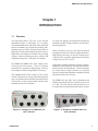
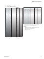
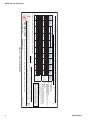
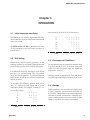
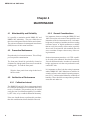
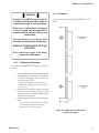
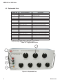
♦ PRECISION INSTRUMENTS FOR TEST AND MEASUREMENT ♦
HRRS 5kV AND 10kV SERIES
High Resistance, 5kV and 10kV
Decade Substituter
User and Service Manual
Copyright © 2013 IET Labs, Inc.
Visit www.ietlabs.com for manual revision updates
HRRS 5kV and 10kV im/January 2013
IET LABS, INC.
www.ietlabs.com
Email: [email protected]
TEL: (516) 334-5959 • FAX: (516) 334-5988
IET LABS, INC.
www.ietlabs.com
Email: [email protected]
TEL: (516) 334-5959 • FAX: (516) 334-5988
HRRS 5kV and 10kV Series
WARRANTY
We warrant that this product is free from defects in material and workmanship and, when properly used,
will perform in accordance with applicable IET specifications. If within one year after original shipment,
it is found not to meet this standard, it will be repaired or, at the option of IET, replaced at no charge when
returned to IET. Changes in this product not approved by IET or application of voltages or currents greater
than those allowed by the specifications shall void this warranty. IET shall not be liable for any indirect,
special, or consequential damages, even if notice has been given to the possibility of such damages.
THIS WARRANTY IS IN LIEU OF ALL OTHER WARRANTIES, EXPRESSED OR IMPLIED,
INCLUDING BUT NOT LIMITED TO, ANY IMPLIED WARRANTY OF MERCHANTABILITY OR
FITNESS FOR ANY PARTICULAR PURPOSE.

i
HRRS 5kV and 10kV Series
WARNING
OBSERVE ALL SAFETY RULES
WHEN WORKING WITH HIGH VOLTAGES OR LINE VOLTAGES.
Dangerous voltages may be present inside this instrument. Do not open the case
Refer servicing to qualified personnel
HIGH VOLTAGES MAY BE PRESENT AT THE TERMINALS OF THIS INSTRUMENT
WHENEVER HAZARDOUS VOLTAGES (> 45 V) ARE USED, TAKE ALL MEASURES TO
AVOID ACCIDENTAL CONTACT WITH ANY LIVE COMPONENTS.
USE MAXIMUM INSULATION AND MINIMIZE THE USE OF BARE
CONDUCTORS WHEN USING THIS INSTRUMENT.
Use extreme caution when working with bare conductors or bus bars.
WHEN WORKING WITH HIGH VOLTAGES, POST WARNING SIGNS AND
KEEP UNREQUIRED PERSONNEL SAFELY AWAY.
CAUTION
DO NOT APPLY ANY VOLTAGES OR CURRENTS TO THE TERMINALS OF THIS
INSTRUMENT IN EXCESS OF THE MAXIMUM LIMITS INDICATED ON
THE FRONT PANEL OR THE OPERATING GUIDE LABEL.
ii

HRRS 5kV and 10kV Series
Table of Contents
Chapter 1 Introduction
1.1 Overview................................................................................................................ 1
Chapter 2 Specifications
2.1 Specifications......................................................................................................... 2
2.2 Ordering Information............................................................................................. 3
Chapter 3 Operation
3.1 Initial Inspection and Setup................................................................................... 5
3.2 Dial Setting............................................................................................................ 5
3.3 Environmental Conditions..................................................................................... 5
3.4 Storage................................................................................................................... 5
Chapter 4 Maintenance
4.1 Maintainability and Reliability.............................................................................. 6
4.2 Preventive Maintenance......................................................................................... 6
4.3 Verification of Performance................................................................................... 6
4.3.1 Calibration Interval...................................................................................... 6
4.3.2 General Considerations................................................................................ 6
4.3.3 Calibration Procedure.................................................................................. 7
4.4 Schematic............................................................................................................... 7
4.5 Replaceable Parts................................................................................................... 8
Figures and Tables
Figure 1-1: Example of an HRRS-5kV unit with 7 decades .................................... 1
Figure 1-2: Example of an HRRS-10kV unit with 4 decades................................... 1
Figure 2-1: Typical operating guide.......................................................................... 4
Figure 4-1: HRRS 5kV and 10kV Series Schematic Diagram................................. 7
Table 4-1: Replaceable Parts................................................................................... 8
Figure 4-2: Replaceable Parts................................................................................. 8

iii
HRRS 5kV and 10kV Series
This page is intentionally left blank.
iv

HRRS 5kV and 10kV Series
Chapter 1
INTRODUCTION
1.1 Overview
The High Resistance, 5kV and 10 kV Decade
Substituters (Figure 1-1 and Figure 1-2) is a family
of instruments that answers the need of the calibration
and test community for decades and working standards that go up to 10 TΩ, offering a broad choice of
high-range, excellent performance resistance sources.
High values of resistance are available for use at high
voltages, without sacrificing accuracy, stability, and
temperature and power coefficients of resistance.
To ensure low leakage, the connection terminals are
insulated with Kel-F high-resistance, non-moistureabsorbing material.
The HRRS-5kV/HRRS-10kV units employ stateof-the-art precision resistors. They are designed
specifically for operation at high voltage, with very
low leakage to minimize degradation of accuracy.
Applications include calibration of meters and megohmmeters, and checking of electrochemical and biomedical sensors and instruments. These instruments
are useful wherever high resistances are required,
such as in testing high-impedance amplifiers and the
insulation of low-power circuits.
The standard models offer a choice of one to nine
decades. The panels are clearly labeled showing the
step size and maximum allowable applied input for
each decade. Custom requirements outside of the
standard models can be satisfied.
Figure 1-1: Example of an HRRS-5kV unit
with 7 decades
Introduction
With a resolution as low as 10 Ω and a maximum
available resistance of 10 TΩ, these High-Resistance,
High-Voltage units may be used for exacting precision high-value resistance applications that require
voltages of up to 5kV or 10 kV.
The HRRS 5kV and 10kV series complement the
HARS series which provides resistance steps as low
as 1 mΩ. The units may be rack-mounted to serve
as components in measurement and control systems.
Figure 1-2: Example of an HRRS-10kV unit
with 4 decades
1
HRRS 5kV and 10kV Series
Chapter 2
SPECIFICATIONS
For convenience to the user, the pertinent specifications are given in an OPERATING GUIDE affixed to the
case of the instrument. Figure 2-1 shows a typical example.
2.1 Specifications
Resistance
per step
Total
decade
resistance
Accuracy *
18-28°C; <50% RH
HRRS-5kV
Q
B
F
HRRS-10kV
Max voltage Maximum Max voltage Maximum
per step
voltage
per step
voltage
(V)
(V)
(V)
(V)
Temperature
coefficient
(±ppm/°C)
Voltage
coefficient
(±ppm/V)
Stability
(±ppm/
yr)
10 Ω
100 Ω
±(0.01%+2 mΩ)
±(0.03%+2 mΩ)
±(0.10%+2 mΩ)
2.5
25
2.5
25
15
-
10
100 Ω
1 kΩ
±(0.01%+2 mΩ
±(0.03%+2 mΩ)
±(0.10%+2 mΩ)
8
80
8
80
5
-
10
1 kΩ
10 kΩ
±0.01%
±0.03%
±0.10%
23
230
23
230
5
-
10
10 kΩ
100 kΩ
±0.01%
±0.03%
±0.10%
70
700
70
700
5
-
10
100 kΩ
1 MΩ
±0.01%
±0.03%
±0.10%
230
2300
230
2300
5
-
10
1 MΩ
10 MΩ
±0.01%
±0.03%
±0.10%
1000
5000
1000
10,000
15
<1
25
5000
5000
5000
(*10,000)
10,000
25
<1
50
10 MΩ
100 MΩ
±0.03%
±0.10%
±1%
100 MΩ
1 GΩ
±0.10%
±0.20%
±1%
5000
5000
10,000
10,000
25
1
100
1 GΩ
10 GΩ
±0.20%
±0.50%
±1%
5000
5000
10,000
10,000
25
1
500
10 GΩ
100 GΩ
±0.50%
±1%
±1%
5000
5000
10,000
10,000
25
2
500
100 GΩ
1 TΩ
±0.50%
±1%
±1%
5000
5000
10,000
10,000
100
5
500
1 TΩ
10 TΩ
±3%
±5%
±10%
5000
5000
10,000
10,000
300
<20 (10 ppm
typical)
500
Resistor type
Wirewound,
non-inductive
High-voltage
film
Tested at low voltages except 10 MΩ at 20 V, 1 GΩ at 100 V, ≥10 GΩ at 1000 V
*To apply up to 10 kV at 10 MΩ, set the 1 MΩ decade to its “10” position.
Zero resistance:
<3 mΩ per decade
Environmental conditions:
Operating Conditions: 10°C to 40°C; <50% RH
Storage conditions: -40°C to 70°C
Mechanical:
Model
Dimensions
Weight
3-4 Decade
Units
43.2 cm W x 13.3 cm H x 13.5 cm D
(17" x 5.25" x 5.3")
(7.5 lbs)
5-7 Decade
Units
48.2 cm W x 22.2 cm H x 33 cm D
5 kg
(19" x 8.75" x 13")
(11 lbs)
8-9 Decade
Units
43.7 cm W x 30.7 cm H x 20.3 cm D
7.7 kg
(17.2" x 12.1" x 8")
(17 lbs)
3.4 kg
Terminals:
Two five-way binding posts on 2 special, lowleakage, Kel-F insulating sockets, and one metal
ground binding post electrically connected to the
case
2
Specifications
HRRS 5kV and 10kV Series
2.2 Ordering Information
Model
Total resistance
Number of
Resolution
decades
Model
Total resistance
Number of
Resolution
decades
HRRS-*-7-10-**
111.111 1 MΩ
7
10 Ω
HRRS-*-7-100-**
1.111 111 GΩ
7
100 Ω
HRRS-*-7-1k-**
11.111 11 GΩ
7
1 kΩ
HRRS-*-7-10k-**
111.111 1 GΩ
7
10 kΩ
100 MΩ
HRRS-*-7-100k-**
1.111 111 TΩ
7
100 kΩ
1 GΩ
HRRS-*-7-1M-**
11.111 11 TΩ
7
1 MΩ
1,111.111 1 MΩ
8
10 Ω
HRRS-*-3-10k-**
11.1 MΩ
3
10 kΩ
HRRS-*-3-100k-**
111 MΩ
3
100 kΩ
HRRS-*-3-1M-**
1.11 GΩ
3
1 MΩ
HRRS-*-3-10M-**
11.1 GΩ
3
10 MΩ
HRRS-*-3-100M-**
111 GΩ
3
HRRS-*-3-1G-**
1.11 TΩ
3
HRRS-*-3-10G-**
11.1 TΩ
3
10 GΩ
HRRS-*-8-10-**
HRRS-*-4-1k-**
11.11 MΩ
4
1 kΩ
HRRS-*-8-100-**
11.111 111 GΩ
8
100 Ω
HRRS-*-4-10k-**
111.1 MΩ
4
10 kΩ
HRRS-*-8-1k-**
111.111 11 GΩ
8
1 kΩ
1,111.111 1 GΩ
8
10 kΩ
HRRS-*-4-100k-**
1.111 GΩ
4
100 kΩ
HRRS-*-8-10k-**
HRRS-*-4-1M-**
11.11 GΩ
4
1 MΩ
HRRS-*-8-100k-**
11.111 111 TΩ
8
100 kΩ
HRRS-*-4-10M-**
111.1 GΩ
4
10 MΩ
HRRS-*-9-10-**
11,111.111 1 MΩ
9
10 Ω
111.111 111 GΩ
9
100 Ω
HRRS-*-4-100M-**
1.111 TΩ
4
100 MΩ
HRRS-*-9-100-**
HRRS-*-4-1G-**
11.11 TΩ
4
1 GΩ
HRRS-*-9-1k-**
1,111.111 11 GΩ
9
1 kΩ
HRRS-*-5-100-**
11.111 MΩ
5
100 Ω
HRRS-*-9-10k-**
11,111.111 1 GΩ
9
10 kΩ
HRRS-*-5-1k-**
111.11 MΩ
5
1 kΩ
HRRS-*-5-10k-**
1.111 1 GΩ
5
10 kΩ
HRRS-*-5-100k-**
11.111 GΩ
5
100 kΩ
HRRS-*-5-1M-**
111.11 GΩ
5
1 MΩ
HRRS-*-5-10M-**
1.111 1 TΩ
5
10 MΩ
HRRS-*-5-100M-**
11.111 TΩ
5
100 MΩ
HRRS-*-6-10-**
11.111 1 MΩ
6
10 Ω
HRRS-*-6-100-**
111.111 MΩ
6
100 Ω
HRRS-*-6-1k-**
1.111 11 GΩ
6
1 kΩ
HRRS-*-6-10k-**
11.111 1 GΩ
6
10 kΩ
HRRS-*-6-100k-**
111.111 GΩ
6
100 kΩ
HRRS-*-6-1M-**
1.111 11 TΩ
6
1 MΩ
HRRS-*-6-10M-**
11.111 1 TΩ
6
10 MΩ
Specifications
*To specify accuracy grade, replace * with “Q,” “B,” or “F” as required.
**To specify voltage, replace ** with either “5kV” or “10kV.”
Options:
-RM: Rack mountable case for standard 19” rack
-K: Kelvin-type 4-terminal posts
-RO: Rear output
3
HRRS 5kV and 10kV Series
10 Ω
100 Ω
1 kΩ
10 kΩ
100 kΩ
1 MΩ
10 MΩ
100 MΩ
1 GΩ
10 GΩ
100 GΩ
Resistance
per step
10 TΩ
100 Ω
1 kΩ
10 kΩ
100 kΩ
1 MΩ
10 MΩ
100 MΩ
1 GΩ
10 GΩ
100 GΩ
1 TΩ
Total
decade
resistance
Q
F
±10%
5000
2.5
8
23
70
230
1000
5000
5000
5000
5000
5000
5000
25
80
230
700
2300
5000
5000
5000
5000
5000
5000
300
15
5
5
5
5
15
25
25
25
25
100
0
0
0
0
0
0.2
<1
1
1
1
2
<20 (10 ppm
typical)
Max voltage Maximum Temperature Voltage
per step
voltage
coefficient coefficient
(V)
(V)
(±ppm/°C)
(±ppm/V)
500
10
10
10
10
10
25
50
100
500
500
500
Stability
(±ppm/
yr)
Terminals:
Two five-way binding posts on 2 special,
low-leakage, Kel-F insulating sockets, and
one metal ground binding post electrically
connected to the case
SN: C1-1250517
Keep unit in a sealed environment when
not in use. Maintain binding post area
clean for minimum electrical leakage.
HRRS-B-9-1K-5kV
High-voltage
film
Wirewound,
non-inductive
Resistor
type
CONSULT INSTRUCTION MANUAL FOR PROPER INSTRUMENT OPERATION
Accuracy *
18-28°C; <50% RH
B
±5%
±(0.01%+2 mΩ) ±(0.03%+2 mΩ) ±(0.10%+2 mΩ)
±(0.01%+2 mΩ ±(0.03%+2 mΩ) ±(0.10%+2 mΩ)
±0.01%
±0.03%
±0.10%
±0.01%
±0.03%
±0.10%
±0.01%
±0.03%
±0.10%
±0.01%
±0.03%
±0.10%
±0.03%
±0.10%
±1%
±0.10%
±0.20%
±1%
±0.20%
±0.50%
±1%
±0.50%
±1%
±1%
±0.50%
±1%
±1%
±3%
MODEL:
Zero resistance:
<3 mΩ per decade
Environmental conditions:
Operating Conditions: 10°C to 40°C; <50% RH
Storage conditions: -40°C to 70°C
HRRS-5kV SERIES HIGH-RESISTANCE, 5kV DECADE SUBSTITUTER OPERATING GUIDE
1 TΩ
Tested at low voltages except 10 MΩ at 20 V, 1 GΩ at 100 V, ≥10 GΩ at 1000 V
WARNING
IET LABS, INC.
www.ietlabs.com
534 Main Street, Westbury, NY 11590 • (516) 334-5959 • (800) 899-8438 • Fax (516) 334-5988
HRRS-5kV lbl/01-17-2013
Observe all safety rules when working with high voltages or line voltages. Connect the (G) terminal to earth ground in order to maintain the case at a safe voltage. Whenever hazardous
voltages (> 45 V) are used, take all measures to avoid accidental contact with any live components: a) Use maximum insulation and minimize the use of bare conductors. b) Remove
power when adjusting switches. c) Post warning signs and keep personnel safely away.
CAGE CODE: 62015
Figure 2-1: Typical operating guide
Specifications
4
HRRS 5kV and 10kV Series
Chapter 3
OPERATION
3.1 Initial Inspection and Setup
and a setting of 10-10-10-l0-10.10 Ω becomes:
This instrument was carefully inspected before shipment. It should be in proper electrical and mechanical
order upon receipt.
1 0 1 0 0 0 0 0 . 0
1 0 1 0 0 0 0 . 0
1 0 1 0 0 0 . 0
1 0 1 0 0 . 0
1 0 1 0 . 0
. 1 0 1 . 0
An OPERATING GUIDE is attached to the case
of the instrument to provide ready reference to
specifications.
3.2 Dial Setting
For additional flexibility and range, each decade
provides a “10” position setting. This “10” position
on any one decade equals the “1” position on the next
higher decade. It adds about 11% to the nominal total
decade resistance.
To determine the resistance obtained when one or
more “10” settings are used, simply add “1” to the
next higher decade. For example, a setting of 3-610-0-10 Ω becomes:
3 3 0 0 0 0
6 6 0 0 0
1 0 1 0 0 0
0 0 0
1 0 1 0
TOT
Operation
11 1 1 1 1.0
3.3 Environmental Conditions
Whenever the dials are used in positions 0-9, the
resulting resistance is read directly. Both the decimal
point and the steps are clearly marked on the panel.
TOT
For optimal accuracy, the decade box should be used
in an environment of 23°C. It should be allowed to
stabilize at that temperature after any significant
temperature variation.
Humidity should be maintained at <50% RH. This is
especially important if high resistances are involved.
3.4 Storage
If this instrument is to be stored for any lengthy period
of time, it should be sealed in plastic and stored in a
dry location. It should not be subjected to temperature
extremes beyond the specifications. Extended exposure to such temperatures can result in an irreversible
change in resistance, and require recalibration.
37 0 1 0
5
HRRS 5kV and 10kV Series
Chapter 4
MAINTENANCE
4.1 Maintainability and Reliability
It is possible to maintain models HRRS-5kV and
HRRS-10kV indefinitely. They are reliable due to
their closed design and sealed switches and resistors.
The units are resistant to electromagnetic interference
(EMI) because of their metal enclosure.
4.2 Preventive Maintenance
Keep the units in a clean environment. This will help
prevent possible contamination.
The front panel should be periodically cleaned to
eliminate any leakage paths from near or around the
binding posts. To clean the front panel:
Wipe the front panel clean using alcohol and a
lint-free cloth.
4.3 Verification of Performance
4.3.2 General Considerations
It is important, whenever testing the HRRS 5kV and
10kV Series units, to be aware of the capabilities and
limitations of the test instruments used. A resistance
bridge may be employed, and there are direct-reading
resistance meters or digital multimeters available
that can verify the accuracy of these units, especially
when used in conjunction with standards that can
serve to confirm or improve the accuracy of the testing instrument
Such test instruments must have a 4:1 TUR capability for each value calibrated. Note that the accuracy
varies for different decades. A number of commercial
bridges and meters exist that can perform this task;
consult IET Labs.
It is important to allow both the testing instrument
and the HRRS-5kV/10kV Substituter to stabilize for
a number of hours at the nominal operating temperature of 23°C, and at nominal laboratory conditions of
humidity. There should be no temperature gradients
across the unit under test.
4.3.1 Calibration Interval
The HRRS 5kV and 10kV Series instruments should
be verified for performance at a calibration interval of
twelve (12) months. This procedure may be carried
out by the user if a calibration capability is available,
by IET Labs, or by a certified calibration laboratory.
If the user should choose to perform this procedure,
then the considerations below should be observed.
6
Maintenance
HRRS 5kV and 10kV Series
WARNING
Connect the GND terminal to earth
or other suitable ground in order to
maintain the case at a safe voltage.
4.4 Schematic
Figure 4-1 shows a schematic of an HRRS-5kV/10kV
unit.
W h e n e v e r h a z a rd o u s vo l t a g e s
(>45 v) are used, take all measures to
avoid accidental contact with any live
components.
Use maximum insulation and
minimize the use of bare conductors.
REMOVE POWER WHEN SETTING
SWITCHES.
Po s t w a r n i n g s i g n s a n d k e e p
personnel safely away.
4.3.3 Calibration Procedure
To calibrate the HRRS-5kV/10kV unit, proceed as
follows
1. Confirm that the leakage resistance between
either binding post and the case ground is
>106 times the highest unit resistance, but
may be as low at 1 TΩ.
If this is not obtained, clean the area
around the binding posts as described in
Section 4.2.
2. Determine the allowable upper and lower
limits for each resistance setting of each
decade based on the specified accuracy (See
Specifications on page 2).
3. Confirm that the resistances fall within these
limits.
If any resistances fall outside thee limits,
the associated switch assembly may
require service or replacement.
Figure 4-1: HRRS 5kV and 10kV Series
Schematic Diagram
Maintenance
7
HRRS 5kV and 10kV Series
4.5 Replaceable Parts
Model Ref
IET part number
Description
1
BP-1000-RD
Binding Post, Red
2
BP-1000-BK
Binding Post, Black
3
BP-1000-BL
Binding Post, Blue
4
BP-1000-GN
Binding Post, Green
5
HARS-X-4300-KNB
Knob Assembly
Not Shown
HARS-X-3100
Foot
Not Shown
HRRS-*-SW-10-**
10 Ω/step Decade Switch Assembly
Not Shown
HRRS-*-SW-100-**
100 Ω/step Decade Switch Assembly
Not Shown
HRRS-*-SW-1k-**
1 kΩ/step Decade Switch Assembly
Not Shown
HRRS-*-SW-10k-**
10 kΩ/step Decade Switch Assembly
Not Shown
HRRS-*-SW-100k-**
100 kΩ/step Decade Switch Assembly
Not Shown
HRRS-*-SW-1M-**
1 MΩ/step Decade Switch Assembly
Not Shown
HRRS-*-SW-10M-**
10 MΩ/step Decade Switch Assembly
Not Shown
HRRS-*-SW-100M-**
100 MΩ/step Decade Switch Assembly
Not Shown
HRRS-*-SW-1G-**
1 GΩ/step Decade Switch Assembly
Not Shown
HRRS-*-SW-10G-**
10 GΩ/step Decade Switch Assembly
Not Shown
HRRS-*-SW-100G-**
100 GΩ/step Decade Switch Assembly
Not Shown
HRRS-*-SW-1T-**
1 TΩ/step Decade Switch Assembly
*To specify accuracy grade, replace * with “Q,” “B,” or “F” as required.
**To specify voltage, replace ** with either “5kV” or “10kV.”
Table 4-1: Replaceable Parts
5
1
2
3
4
Figure 4-2: Replaceable Parts
8
Maintenance