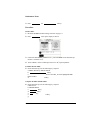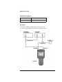
1
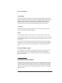
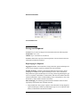
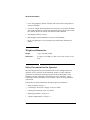
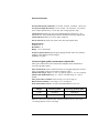
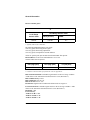
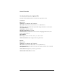
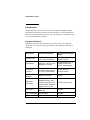
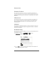
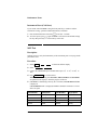
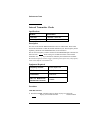
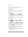
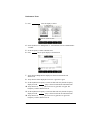
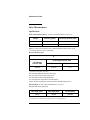
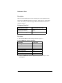
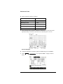
Service Manual
Service Manual
Latest Agilent ProBER 2 Information
For the latest Agilent ProBER 2 information, please refer to the following URLs on the WorldWide Web:
http://www.tm.agilent.com/tmo/datasheets/English/HPE7580A.html
http://hpweb.sqf.hp.com/qto/support/supplayo.htm
(Scroll down until you reach Product Service Information and select E7580A ProBER.)
Agilent ProBER 2
Contents
1 General Information
Warranty 1-2
Responsibilities of the Customer 1-3
Certification 1-4
Assistance 1-4
Notice 1-4
Restricted Rights Legend 1-4
Instrument Serial Number 1-4
Storage and Shipment 1-5
Repackaging for Shipment 1-5
Weight and Dimensions 1-6
Safety Precautions for the Operator 1-6
Safety Symbols 1-7
Additional Precautions for Service Engineers 1-8
ESD Precautions 1-8
Operator’s Maintenance 1-9
Cabinet Cleaning 1-9
Battery Replacement 1-9
Statement of Compliance 1-10
Australian EMC Regulations 1-10
Noise Declaration (German) 1-10
Electromagnetic Compatibility 1-10
Declaration of Conformity 1-11
Specifications 1-12
2 Performance Tests
Introduction 2-2
Equipment Required 2-2
Performance Test Record 2-3
Calibration Cycle 2-3
Adjustments 2-3
Recall Default Settings 2-3
Instrument Reset (Cold Start) 2-4
Self-Test 2-4
Internal Transmitter Clocks 2-5
Transmitter Output 2-7
Contents - 1
Contents
Frequency Measurement and Looped Clock 2-10
Jitter Measurement 2-13
Performance Test Record 2-17
3 Repair
Repair Policy 3-2
Block Diagrams 3-2
Troubleshooting 3-4
Replacing the Battery 3-6
Replacing the Board Assemblies 3-8
Replacing the Power Supply Board 3-9
Replacing the Processor Board 3-10
Replacing the Display Assembly 3-12
Replaceable Parts 3-13
4 Calibration and Self-Test
Pre-Calibration Procedure 4-2
Erasing Existing Calibration Data 4-2
Entering the Serial Number 4-2
Enabling Option 002 4-3
Setting the Time and Date 4-3
Calibration 4-4
Test Equipment 4-4
Accessing the Calibration Menu 4-4
Calibration Test Equipment Setup 4-5
Self-Test 4-6
Speaker/Microphone Test 4-6
Contents - 2
1
1
1 General Information
This section includes essential safety information for both
operators and service engineers, as well as full specifications
for ProBER 2.
General Information
Warranty
Agilent Product
Agilent ProBER 2
Duration of Warranty
1 year
1 Agilent Technologies warrants Agilent hardware, accessories and supplies
against defects in materials and workmanship for the period specified above.
If Agilent receives notice of such defects during the warranty period, Agilent
will, at its option, either repair or replace products which prove to be defective.
Replacement products may be either new or like-new.
2 Agilent Technologies warrants that Agilent software will not fail to execute its
programming instructions, for the period specified above, due to defects in
material and workmanship when properly installed and used.
If Agilent receives notice of such defects during the warranty period, Agilent will
replace software media which does not execute its programming instructions due
to such defects.
3 Agilent Technologies does not warrant that the operation of Agilent products will
be uninterrupted or error free.
If Agilent is unable, within a reasonable time, to repair or replace any product to
a condition as warranted, customer will be entitled to a refund of the purchase
price upon prompt return of the product.
4 Agilent Technologies products may contain remanufactured parts equivalent to
new in performance or may have been subject to incidental use.
5 The warranty period begins on the date of delivery or on the date of installation
if installed by Agilent. If customer schedules or delays Agilent installation more
than 30 days after delivery, warranty begins on the 31st day from delivery.
6 Warranty does not apply to defects resulting from (a) improper or inadequate
maintenance or calibration, (b) software, interfacing, parts or supplies not
supplied by Agilent, (c) unauthorized modification or misuse, (d) operation
outside of the published environmental specifications for the product, or (e)
improper site preparation or maintenance.
7 TO THE EXTENT ALLOWED BY LOCAL LAW, THE ABOVE
WARRANTIES ARE EXCLUSIVE AND NO OTHER WARRANTY OR
CONDITION, WHETHER WRITTEN OR ORAL, IS EXPRESSED OR
IMPLIED AND AGILENT TECHNOLOGIES SPECIFICALLY DISCLAIMS
ANY IMPLIED WARRANTIES OR CONDITIONS OF
1-2
General Information
MERCHANTABILITY, SATISFACTORY QUALITY, AND FITNESS FOR A
PARTICULAR PURPOSE.
8 Agilent Technologies will be liable for damage to tangible property per incident
up to the greater of $300,000 or the actual amount paid for the product that is the
subject of the claim, and for damages for bodily injury or death, to the extent that
all such damages are determined by a court of competent jurisdiction to have been
directly caused by a defective Agilent product.
9 TO THE EXTENT ALLOWED BY LOCAL LAW, THE REMEDIES IN THIS
WARRANTY STATEMENT ARE CUSTOMER’S SOLE AND EXCLUSIVE
REMEDIES. EXCEPT AS INDICATED ABOVE, IN NO EVENT WILL
AGILENT OR ITS SUPPLIERS BE LIABLE FOR LOSS OF DATA OR FOR
DIRECT, INCIDENTAL, SPECIAL, CONSEQUENTIAL (INCLUDING
LOST PROFIT OR DATA), OR OTHER DAMAGE, WHETHER BASED IN
CONTRACT, TORT, OR OTHERWISE.
FOR CONSUMER TRANSACTIONS IN NEW ZEALAND AND AUSTRALIA:
THE WARRANTY TERMS CONTAINED IN THIS STATEMENT, EXCEPT TO
THE EXTENT LAWFULLY PERMITTED, DO NOT EXCLUDE, RESTRICT OR
MODIFY AND ARE IN ADDITION TO THE MANDATORY STATUTORY
RIGHTS APPLICABLE TO THE SALE OF THIS PRODUCT TO YOU.
Responsibilities of the Customer
The customer shall provide:
1 Access to the products during the specified periods of coverage to perform
maintenance.
2 Adequate working space around the products for servicing by Agilent personnel.
3 Access to and use of all information and facilities determined necessary by
Agilent to service and/or maintain the products. (Insofar as these items may
contain proprietary or classified information, the customer shall assume full
responsibility for safeguarding and protection from wrongful use.)
4 Routine operator maintenance and cleaning as specified in the Agilent Operating
and Service Manuals.
5 Consumables such as paper, disks, magnetic tapes, ribbons, inks, pens, gases,
solvents, columns, syringes, lamps, septa, needles, filters, frits, fuses, seals,
detector flow cell windows, etc.
1-3
General Information
Certification
Agilent Technologies certifies that this product met its published specifications at
the time of shipment from the factory. Agilent Technologies further certifies that its
calibration measurements are traceable to the United States National Bureau of
Standards, to the extent allowed by the Bureau’s calibration facility and to the
calibration facilities of other International Standards Organization members.
Assistance
Product maintenance agreements and other customer assistance agreements are
available for Agilent Technologies products.
Notice
The information contained in this document is subject to change without notice.
Agilent Technologies shall not be liable for errors contained herein or for incidental
or consequential damages in connection with the furnishing, performance or use of
this material.
This document contains proprietary information which is protected by copyright.
All rights are reserved. No part of this document may be photocopied or reproduced
without the prior written consent of the manufacturer, Agilent Technologies UK
Ltd.
Restricted Rights Legend
Use, duplication, or disclosure by the government is subject to restrictions as set
forth in subdivision (b)(3)(ii) of the Rights in Technical Data and Computer
Software clause at 52.227-7013. Agilent Technologies, Inc; 395 Page Mill Road;
Palo Alto, California.
Instrument Serial Number
Attached to the lower shell of the instrument is a serial number label on which is a
two-letter reference denoting country of origin (GB = Great Britain) and an eightdigit serial number. The serial number is unique to each instrument and should be
quoted in all correspondence with Agilent Technologies, especially when ordering
replacement parts.
1-4
General Information
Serial Number Plate
Storage and Shipment
ProBER 2 may be stored or shipped in environments within the following limits:
Temperature: 0 to +55oC.
Altitude: Up to 15,200 meters (50,000 feet).
ProBER 2 should also be protected from temperature extremes which could cause
condensation within the instrument.
Repackaging for Shipment
Tagging for Service. If the instrument is being returned to Agilent Technologies for
service, please complete a repair tag and attach it to the instrument.
Original Packaging. Containers and materials identical to those used in factory
packaging are available from Agilent Technologies offices. If the instrument is
being returned to Agilent Technologies for servicing, attach a tag indicating the type
of service required, return address, model number, and full serial number. Mark the
container FRAGILE to ensure careful handling. In any correspondence, refer to the
instrument by model number and full serial number.
Other Packaging. The following general instructions should be followed when
repackaging with commercially available materials:
• Wrap instrument in heavy paper or plastic. If the instrument is being shipped to
Agilent Technologies, attach a tag indicating the type of service required, return
address, model number and full serial number.
1-5
General Information
• Use a strong shipping container. A double wall carton made of 350 pound test
material is adequate.
• Use a layer of shock absorbing material 70 to 100 mm (3 to 4 in) thick, around all
sides of the instrument to provide firm cushioning and prevent movement inside
the container. Protect the controls and connectors with cardboard.
• Seal shipping container securely.
• Mark shipping container FRAGILE to ensure careful handling.
• In any correspondence, refer to instrument by model number and full serial
number.
Weight and Dimensions
Weight:
1 kg (2.2 lb) fully loaded.
Dimensions:
275 mm (10.8 in) high, 127 mm (5.0 in) wide, 55 mm (2.2 in)
deep.
Safety Precautions for the Operator
The following general safety precautions must be observed during all phases of
operation, service, and repair of this instrument. Failure to comply with these
precautions or with specific warnings elsewhere in this manual violates safety
standards of design, manufacture, and intended use of the instrument. Agilent
Technologies assumes no liability for the customer’s failure to comply with these
requirements.
In particular, the operator should note the following safety information:
• "Safety Symbols" on page 1-7.
• “Connecting to the ac Power Supply” in the User Guide.
• “Operating Environment” in the User Guide.
• "Replacing the Battery" on page 3-6.
• "Operator’s Maintenance" on page 1-9.
1-6
General Information
DO NOT operate damaged equipment: Whenever it is possible that the safety
protection features built into this product have been impaired, either through
physical damage, excessive moisture, or any other reason, REMOVE POWER and
do not use the product until safe operation can be verified by service-trained
personnel. If necessary, return the product to a Agilent Technologies Sales and
Service Office for service and repair to ensure the safety features are maintained.
Safety Symbols
The following symbols on the instrument and in the manual indicate precautions
which must be taken to maintain safe operation of the instrument.
The product is marked with this symbol when it is necessary for the
user to refer to the instructions in the supplied documentation.
Indicates the field wiring terminal that must be connected to earth
ground before operating the equipment - protects against electrical
shock in case of fault.
Frame or chassis ground terminal - typically connects to the
equipment’s metal frame.
Alternating current (ac).
Direct current (dc).
Indicates hazardous voltages.
Equipment protected throughout by Double Insulation or Reinforced
Insulation, equivalent to Class II of IEC 536.
1-7
General Information
WA RN IN G
Warning denotes a hazard. It calls attention to a procedure, which if not
correctly performed or adhered to could result in injury or loss of life. Do not
proceed beyond a warning until the indicated conditions are fully understood
and met.
CA UTI O N
Caution denotes a hazard. It calls attention to a procedure, which if not correctly
performed or adhered to could result in damage to or destruction of the instrument.
Do not proceed beyond a caution until the indicated conditions are fully understood
and met.
Additional Precautions for Service Engineers
DO NOT substitute parts or modify equipment: Because of the danger of
introducing additional hazards, do not install substitute parts or perform any
unauthorized modification to the product. Return the product to a Agilent
Technologies Sales and Service Office for service and repair to ensure the safety
features are maintained.
DO NOT service or adjust alone: Under certain conditions, dangerous voltages may
exist even with the equipment switched off. To avoid dangerous electrical shock,
service personnel must not attempt internal service or adjustment unless another
person, capable of rendering first aid and resuscitation, is present.
ESD Precautions
CA UTI O N
When connecting or disconnecting ProBER 2, ensure that you are grounded to bring
you and the instrument to the same static potential.
ProBER 2 contains components sensitive to electrostatic discharge.
To prevent component damage, carefully observe the handling precautions that
follow.
1-8
General Information
The smallest static voltage most people can feel is about 3500 V. It takes less than
one tenth of that (about 300 V) to destroy or severely damage static sensitive
circuits. Often, static damage does not immediately cause a malfunction but
significantly reduces the component’s life. Adhering to the following precautions
will reduce the risk of static discharge damage.
•
•
•
Keep ProBER 2 in its conductive storage box (the one it was shipped in) when
not in use. Save this box for future storage of the unit. Alternatively, keep it in its
soft carrying case (Option 020) if this was ordered with the instrument.
Before handling ProBER 2, select a work area where potential static sources are
minimized. Avoid working in carpeted areas and non-conductive chairs. Keep
body movement to a minimum. Agilent Technologies recommends that you use
a controlled static workstation.
Hold ProBER 2 by its handle. Avoid touching any components or edge
connectors.
Anti-Static Products
The following anti-static products are available from Agilent Technologies:
• Anti-static workstation - Part Number 9300-0792
• Wrist-Strap and cord - Part Number 9300-0970
Operator’s Maintenance
Maintenance appropriate for the operator is:
• Cabinet cleaning.
• Battery replacement.
Cabinet Cleaning
Clean the cover using a damp cloth only.
Battery Replacement
See "Replacing the Battery" on page 3-6.
WA RN IN G
REFER SERVICING TO QUALIFIED PERSONNEL.
1-9
General Information
Statement of Compliance
This instrument has been designed and tested in accordance with IEC Publication
1010-1 + A1:1992 Safety Requirements for Electrical Equipment for Measurement,
Control and Laboratory Use, and has been supplied in a safe condition. The
instruction documentation contains information and warnings which must be
followed by the user to ensure safe operation and to maintain the instrument in a
safe condition.
The CE mark shows that the product complies with all relevant
European legal Directives.
ISM 1-A
This is a symbol of an Industrial Scientific and Medical Group 1
Class A product.
Australian EMC Regulations
The C-Tick mark is a registered trademark of the Spectrum
Management Agency of Australia. This signifies compliance with
the Australian EMC Framework Regulations under the terms of
the Radiocommunications Act of 1992.
Noise Declaration (German)
LpA < 70 dB
am Arbeitsplatz (operator position)
normaler Betrieb (normal position)
nach DIN 45635 pt.19 (per ISO 7779)
Electromagnetic Compatibility
ProBER 2 has been designed to meet the protection requirements of the European
Communities Electromagnetic Compatibility (EMC) directive 89/336/EEC. In order
to preserve the EMC performance of the product, any cable which becomes worn or
damaged must be replaced with the same type and specification.
1-10
General Information
Declaration of Conformity
DECLARATION OF CONFORMITY
According to ISO/IEC Guide 22 and CEN/CENELEC EN45014
Manufacturer’s Name:
Agilent Technologies UK Limited
Manufacturer’s Address:
Telecomms Networks Test Division
South Queensferry
West Lothian, EH30 9TG
Scotland, United Kingdom
Declares that the product
Product Name:
ProBER 2, 2Mb/s Handheld Test Set
Model Number:
E7580A
Product Options:
This declaration covers all options of the above product as detailed in
TCF A-5951-9852-01.
EMC:
Conforms with the protection requirements of European Council Directive 89/336/EEC on the approximation of the
laws of the member states relating to electromagnetic compatibility, against EMC test specifications EN 55011:1991
(Group 1, Class A) and EN 50082-1:1992.
As Detailed in:
Electromagnetic Compatibility (EMC)
Technical Construction File (TCF) No. A-5951-9852-01
Assessed by:
DTI Appointed Competent Body
EMC Test Centre,
GEC-Marconi Avionics Ltd.,
Maxwell Building,
Donibristle Industrial Park,
Hillend,
Dunfermline
KY11 9LB
Scotland, United Kingdom
Technical Report Number:6893/2200/CBR, dated 21 August 1997
Safety:
The product conforms to the following safety standards:
IEC 61010-1(1990) +A1(1992) +A2(1995) / EN 61010-1:1993
IEC 60825-1(1993) / EN 60825-1:1994
Canada / CSA-C22.2 No. 1010.1-93
The product herewith complies with the requirements of the Low Voltage Directive 73/23/EEC, and carries the CE
mark accordingly.
South Queensferry, Scotland.
01 June 2000
W.R. Pearson / Quality Manager
For further information, please contact your local Agilent Technologies sales office, agent, or distributor.
1-11
General Information
Specifications
Except where otherwise stated, the following parameters are warranted performance
specifications. Parameters described as “typical” or “nominal” are supplemental
characteristics which provide a useful indication of typical but non-warranted
performance characteristics.
Transmitter
Bit rate: 2.048 Mb/s.
Line code: HDB3 or AMI.
Connectors:
BNC nominal 75Ω unbalanced.
3-pin Siemens nominal 120Ω balanced.
Mark level:
75Ω unbalanced - 2.37 V±10%.
120Ω balanced - 3.0 V±10%.
Clock source: Internal, recovered, external.
Internal clock accuracy: ±4.6 ppm.
Recovered clock range: 2.048 Mb/s ±100 ppm.
External clock: As ITU-T G.703 Section 10 (Reference 1). Will not operate if
derived from coded (HDB3/AMI) source.
Clock frequency offset: Preset, user.
Preset offset: ±50 ppm.
User offset: ±100 ppm in 1 ppm steps.
Test patterns
PRBS: 29-1, 211-1, 215-1, 220-1, 223-1 as per ITU-T O.151, O.152, O.153.
Word: User-defined 8-bit word, user-defined 16-bit word, all-ones, all-zeros, 1010,
1000.
Voice channel insert: Single tone, DTMF dialling.
Tone frequency: 300 Hz to 3400 Hz in 1 Hz steps.
Tone level: -40 dB to -20 dB in 5dB steps; -20 dB to +3 dB in 1 dB steps.
Error add: Bit, FAS, CRC4, Code, E-Bit.
Bit, CRC4, Code, E-Bit rate: Single, 1 in 103, 1 in 104, 1 in 105, 1 in 106, 1 in 107.
FAS rate: 1 frame error in 4 framing words, 2 in 4, 3 in 4, 4 in 4.
Alarm generation: LOS, AIS, LOF, TS AIS, RDI, RDI MF.
Background fill signal: Each background timeslot comprises a fixed byte which
contains a number relating to its position in the 2 Mb/s structure.
1-12
General Information
Framing: Standard (PCM31),
CRC4 multiframe (PCM31CRC),
standard with timeslot 16 CAS multiframe (PCM30),
CRC4 multiframe with timeslot 16 CAS multiframe (PCM30CRC).
User defined framing bits
PCM31, PCM31CRC: Remote alarm, spare bits (As per ITU-T G.704 reference 2).
PCM30, PCM30CRC: Remote alarm, remote CAS alarm, ABCD signaling bits,
spare bits (As per ITU-T G.704 reference 2).
Unframed
Receiver
Bit rate: 2.048 Mb/s.
Connectors:
BNC 75Ω unbalanced.
3-pin Siemens 120Ω balanced.
Bridged Input:
Unbalanced 1.2 kΩ (nominal).
Balanced 1 kΩ (nominal).
Line code: HDB3 or AMI.
Mark level:
75Ω unbalanced - 2.37 V peak.
120Ω balanced - 3.0 V peak.
Return loss: As ITU-T G.703 (Reference 1).
Clock capture range: 2.048 Mb/s ±100 ppm.
Test patterns
PRBS: 29-1, 211-1, 215-1, 220-1, 223-1.
Word: User-defined 8-bit word, user-defined 16-bit word, all-ones, all-zeros, 1010,
1000.
Live traffic: No test pattern expected during in-service measurements.
n x 64 kb/s: Contiguous or non-contiguous timeslots.
Framing: Standard (PCM31),
CRC4 multiframe (PCM31CRC),
standard with timeslot 16 CAS multiframe (PCM30),
CRC4 multiframe with timeslot 16 CAS multiframe (PCM30CRC).
Reported framing bits
PCM31: Remote alarm, spare bits (As per ITU-T G.704 Reference 2).
PCM31CRC: Remote alarm, remote end block alarm, spare bits, Si bits (As per
ITU-T G.704 Reference 2).
PCM30: Remote alarm, remote CAS alarm, ABCD signaling bits, spare bits (As per
ITU-T G.704 Reference 2).
1-13
General Information
PCM30CRC: Remote alarm, remote CAS alarm, remote end block alarm, ABCD
signaling bits, spare bits, Si bits (As per ITU-T G.704 Reference 2).
Frame alignment 2 Mb/s: As per ITU-T Rec. G.706 (Reference3).
Frame gain 2 Mb/s: 1 Correct sequence of FAS-NFAS-FAS.
Frame loss 2 Mb/s: 3 consecutive incorrect FAS or NFAS words.
Frame alignment 2 Mb/s CRC4: As per ITU-T Rec. G.706 (Reference 3).
Frame alignment 2 Mb/s CAS: As per ITU-T Rec. G.732 (Reference 4).
Frame gain 2 Mb/s CAS: 1 correct CAS multiframe and the previous CAS word is
not 0000.
Frame loss 2 Mb/s CAS: 2 consecutive errored CAS multiframe patterns or 16
frames with CAS word 0000.
Input mode & signal conditioning
Terminated: 2.37 V unbalanced, 3.0V balanced.
Equalization at f/2: 6 dB.
Monitor gain: 20 dB, 26 dB, 30 dB.
Monitor equalization at f/2: 6 dB.
Pattern gain: 32 consecutive error free bits received.
Pattern loss:
PRBS: BER ≥ 20% for 10 consecutive 100 ms periods.
Word: BER ≥ 4%.
Jitter tolerance: As per ITU-T Rec G.823 (Reference 8).
Voice channel monitor
Frequency measurement range: 300 Hz to 3400 Hz.
Frequency measurement accuracy: ±1 Hz.
Level measurement accuracy
-60 dB to -20 dB: ±5 dB.
-20 dB to +3 dB: ±1 dB.
Autosetup: Detects and matches, if possible, the line rate framing and test pattern of
an incoming signal.
Test period: Manual, single, delayed.
Manual: Start by pressing START/STOP , will continue until START/STOP is
pressed.
Single: Fixed duration. Started by pressing START/STOP and stops when fixed
duration has passed. Can be stopped sooner by pressing START/STOP .
Delayed: Fixed duration. Starts when user-selected date & time is reached and stops
when fixed duration has passed. Can be stopped sooner by pressing
START/STOP .
1-14
General Information
Fixed periods (Single & Delayed): 10 seconds, 1 minute, 15 minutes, 1 hour, User.
User periods (Single & Delayed): 1 to 59 seconds, 1 to 59 minutes, 1 to 23 hours
(Line voltage operation only), 1 to 99 days (Line voltage operation only).
Alarms detected: LOS, LOF, AIS, TS AIS, RDI, RDI MF, pattern loss, CAS
multiframe loss. Jitter Unlocked (Option 002), and Jitter Over-range (Option 002).
Alarm indicators: Battery low, error, alarm, signal loss.
Errors detected: Bit, FAS, CRC, E-Bit, Code, Jitter Hits (Option 002).
Round trip delay
Accuracy: ±1 µs.
Resolution: 1 µs.
Range: 1 µs to 1999.999 ms.
Frequency measurement: Input frequency displayed in Hz with 1 Hz resolution,
frequency offset displayed in Hz and ppm.
Accuracy: ±4.6 ppm.
Advanced signal quality measurement (Option 001)
Allows jitter measurement, level measurement and pulse mask verification on
received 2.048 Mb/s signals.
Jitter measurement: Jitter is measured on the received signal using the recovered
clock of 2.048 Mb/s with up to ±50 ppm of frequency offset.
Measurement ranges: Range 1.6 - 0 to 1.6 UI pk-pk; range 16 - 0 to 15.5 UI pk-pk.
Measurement bandwidth: Range 1.6 - 2 Hz to >100 kHz, range 16 - 2 Hz to
50 kHz.
Jitter peak results resolution: 0.001 UI range 1.6, 0.01 UI range 16.
Hit threshold resolution: 0.01 UI range 1.6, 0.1 UI range 16.
Peak measurement accuracy: To ITU-T Recommendation O.171/O.172.
Range
Accuracy (peak)
Accuracy (peak-to-peak)
1.6 UI
±5%±X±Y
±5%±X±2Y
16 UI
±5%±X±Y
±5%±X±2Y
Where X is the receiver intrinsic jitter as described below, and Y is 0.01 UI for
1.6 UI range and 0.03 UI for 16 UI range.
1-15
General Information
Receiver intrinsic jitter:
X
16 UI Range Intrinsic Jitter
1.6 UI Range
Intrinsic Jitter
Clock (all ones)
0.02 UI
PRBS
0.07 UI
0.11
1. Typically 0.05 UI after calibration.
The following additional intrinsics may apply:
0.02 UI (typical) when using monitor gain.
0.01 UI (typical) when using equalization.
0.01 UI (typical) at temperatures outwith ambient.
Values are peak-to-peak jitter measured with LP and HP1 filter present.
Internal filters: To ITU-T Recommendation O.171/O.172.
Nominal 3dB corner frequencies
HP1 (high pass)1
HP1 (high pass)
LP (low pass)
20 Hz
18 kHz
100 kHz
1. Conforms to the mask limits specified in ITU-T O.172 Appendix IV.
Pulse mask measurement: 2.048 Mb/s signal must be in the level range -28 dB to
+4 dB relative to the nominal level defined in ITU-T G.703 (Reference 1).
Pulse width accuracy: ±20 ns.
Pulse width ratio: 0.95 to 1.05.
Pulse level ratio: 0.95 to 1.05.
Pass/fail test: Signal must be within mask defined in G.703, Figure 15.
Level measurement: 2.048 Mb/s signal must be in the level range -28 dB to + 4dB
relative to the nominal level defined in ITU-T G.703 (Reference 1).
Resolution: 1 dB.
Level accuracy:
-10 dB to +4 dB: ±1 dB.
-20 dB to -10 dB: ±2 dB.
-36 dB to -20 dB: ±3 dB.
1-16
General Information
Co-directional interface (Option 002)
Provides 64 kb/s transmit and receive interfaces as per ITU-T G.703.
Transmitter
Rate: 64 kb/s.
Connector: 3-pin Siemens, 120Ω balanced.
Line Code: As per ITU-T G.703 section 1.2.1.1.5 (Reference 1).
Mark level: The pulse mask at the output will comply with ITU-T G.703 section
1.2.1.2 (Reference 3).
Clock source: Internal, external.
Internal clock accuracy: ±4.6 ppm.
External clock: Divided-down version of a clock complying with ITU-T G.703
Section 10 (Reference 1).
Error add: Bit.
Rate: Single,1 in 103, 1 in 104, 1 in 105, 1 in 106, 1 in 107.
Alarm Generation: Loss of signal, octet loss, pattern loss.
Receiver
Rate: 64 kb/s.
Connector: 3-pin Siemens, 120Ω balanced.
Line code: As per ITU-T G.703 section 1.2.1.1.5 (Reference 1).
Operating level: The pulse mask at the input will comply with ITU-T G.703 section
1.2.1.2 (Reference 3).
Alarms detected: Signal loss, octet loss, pattern loss.
Measurement results: Bit error count.
1-17
1-18
2
2
2 Performance Tests
In this section you will find procedures for verifying the
performance of ProBER 2.
Performance Tests
Introduction
The procedures given here test the electrical performance of ProBER 2 using as
performance standards the Specifications listed in Section 1, General Information.
Each test is self contained and, therefore, may be performed as a stand-alone test or
as part of full instrument calibration.
Equipment Required
Equipment required for the Performance Tests is listed below. Any equipment
which meets or exceeds the critical specification of the equipment listed, may be
substituted.
Instrument
Critical Specification
Recommended Agilent
Model
Oscilloscope
400 MHz Bandwidth,
1 MΩ Input Termination
54520A Opt 001 or
54810A Opt 001
Synthesizer
Sinewave 1 kHz to 5 kHz
Amplitude +10 dBm
3335A Opt 010 (75Ω) or
3325B & 8657A with
50/75Ω matching pad
Frequency
Counter
Range 0 to 5 MHz,
2 channels with accuracy
<0.1 ppm. (Ratio Mode)
5335A Opt 010 or
53181A Opt 001
Spectrum
Analyzer
Range 0 to 10 MHz
8560E
BER/Jitter
Generator
2.048 Mb/s Line Rate with
PCM30 Framing, Jitter
Frequency range 2 Hz to
100 kHz, Jitter Amplitude
Range 0.5 UI to 16 UI
37718C Opt 012, 200
Converter
75Ω Unbalanced to 120Ω
Balanced
15508C
75Ω Termination
0 to 200 MHz
11094B
T Connector
BNC to Dual BNC
1250-0781
2-2
Performance Tests
Performance Test Record
The results of the Performance Tests may be recorded on the performance test
record at the end of this section. The results recorded at incoming inspection may be
used for comparison during periodic maintenance, troubleshooting or after repair or
adjustment.
Calibration Cycle
This instrument requires periodic verification of performance. Depending on use
and environmental conditions, the instrument should be checked approximately
once a year, using these Performance Tests. Full calibration details are given
starting on page 4-1.
Adjustments
This product has no adjustable components. If it fails a performance test and is out
of specification, you will need to replace the appropriate assembly if re-calibration
does not solve the problem.
Recall Default Settings
The Performance Tests require ProBER 2 to be set to a pre-defined (default) state at
the beginning of each test.
1 Using the cursor control keys
,
,
Inst. Settings display as shown below.
and
, set up the Other
2 Press Recall to recall the instrument default settings.The status display will
indicate stored settings number 0 recalled.
2-3
Performance Tests
Instrument Reset (Cold Start)
If you cannot control ProBER 2 using the front panel keys, in other words the
software has “hung”, perform an Instrument Reset (Cold Start).
1 Press and hold down the On/Off key
for at least 7 seconds.
2 To restore power, press
again. ProBER 2 will return to the Default settings
but any data previously stored in memory will be lost.
Self-Test
Description
Self Test is run to verify the functionality of the instrument prior to carrying out the
performance tests.
Procedure
1 Select MENU Other
2 Select Auto Tests
,
Selftest to obtain the Selftest display.
All Tests .
3 Connect the TRANSMIT port to the RECEIVE port, 75Ω to 75Ω or 120Ω to
120Ω.
4 Press START/STOP to run the selftest.
While the tests are running, the Test Name, Subtest Number and Test Status
are updated on the display to show the progress of the test.
5 If ProBER 2 is functioning correctly, after 3 minutes, Overall Status PASSED
is displayed.
If Overall Status FAIL is displayed, ProBER 2 should be returned to a service
office for repair.
Fail Number
Description
Fail Number
Description
1xxxx
CPU
5xxxx
BER
2xxxx
Real Time Clock
6xxxx
Pulse Mask
3xxxx
Line Level
7xxxx
Jitter
4xxxx
Clock
8xxxx
Delay
2-4
Performance Tests
Internal Transmitter Clocks
Specifications
Bit Rate
Specification
2.048 MHz
2.048 MHz ± 9.421 Hz
64 kHz (Opt 002)
64 kHz ± 0.3 Hz
Description
This test verifies that the PDH transmit data rates are within limits. These limits
assume the instrument is within the annual calibration cycle. The Frequency Offset
capability (deviation from Standard Bit Rate) is also tested here.
The test uses a Frequency Counter connected to the TRANSMIT port to measure the
data rate on an All 1’s pattern. This gives an indirect measure of the internal
transmitter clock frequency as the data is clocked by the internal clock oscillator.
Because the Frequency Counter triggers from the positive pulses only, the frequency
count will be half the selected data rate.
Equipment Required
Frequency Counter
5335A Option 010
75Ω Termination
11094B
T Connector
1250-0781
120Ω/75Ω Balanced to
Unbalanced Converter
15508C
Procedure
2.048 Mb/s Interface
1 Recall the ProBER 2 default settings as shown on page 2-3 and on the
Tx/Rx Setup display, select Frame Structure Unframed and Test Pattern
All 1’s .
2-5
Performance Tests
2 Connect the Unbalanced TRANSMIT port to the Frequency Counter. Terminate
the Frequency Counter input in 75Ω (use the T connector).
3 Set the Frequency Counter to:
FUNCTION - FREQ A
ATTEN - X10
4 Adjust the Frequency Counter ATTEN and trigger level to obtain a stable reading
and ensure that the Frequency Counter reads between 1023995.39 Hz and
1024004.61 Hz.
64 kHz Interface (Option 002 Only)
5 On the Tx/Rx Setup display, set the Transmit Line Rate to 64 kb/s with the
Test Pattern set to All 1’s and the Octet Timing to Octet Off .
6 Connect the Balanced TRANSMIT port to the Frequency Counter via the 120Ω/
75Ω Balanced to Unbalanced Converter. Terminate the Frequency Counter input
in 75Ω (use the T connector).
7 Adjust the Frequency Counter trigger level to obtain a stable reading and ensure
that the Frequency Counter reads between 31999.85 Hz and 32000.15 Hz.
2 Mb/s Frequency Offsets
8 On the Tx/Rx Setup display, select Transmit Line Rate 2 Mb/s , Frame
Structure Unframed and Test Pattern All 1’s . Connect the unbalanced
TRANSMIT port to the Frequency Counter. Terminate the Frequency Counter
input in 75Ω (use the T connector).
9 On the Test Setup display, select Freq Offset and OFFSET +50 ppm .
Adjust the Frequency Counter trigger level to obtain a stable reading and ensure
that the Frequency Counter reads between 1024046.59 Hz and 1024055.8 Hz.
10 Select OFFSET -50 ppm , adjust the Frequency Counter trigger level to obtain
a stable reading and ensure that the Frequency Counter reads between
1023944.02 Hz and 1023953.41 Hz.
11 Select Edit , set OFFSET +100 ppm, adjust the Frequency Counter trigger
level to obtain a stable reading and ensure that the Frequency Counter reads
between 1024097.79 Hz and 1024107.0 Hz.
12 Select Edit , set OFFSET -100 ppm, adjust the Frequency Counter trigger level
to obtain a stable reading and ensure that the Frequency Counter reads between
1023893.0 Hz and 1023902.2 Hz.
2-6
Performance Tests
Transmitter Output
Specifications
Pulse Shape: As per ITU Rec. G.703.
Pulse Amplitude:
120Ω Balanced
3.00 V ±10%
75Ω Unbalanced
2.37 V ±10%
Description
This test verifies that the transmitter output level and pulse shape meets the required
ITU specification. The Unbalanced TRANSMIT port is connected to an
Oscilloscope and the waveform is checked for amplitude and duty cycle at the
nominal mid-points. The waveform shape is also checked by comparison with the
special ITU masks.
NOT E
This performance test is written using the 54520A Oscilloscope with Option 001 Telecom Masks Application. If any other Oscilloscope is used the keystrokes given
in this procedure will not apply. The Positive pulse masks are contained in the ROOT
directory of the Telecom Mask Application Disk and the Negative pulse masks are
in the INV_MASK directory.
Equipment Required
Oscilloscope
54520A Option 001
T Connector
1250-0781
75Ω Termination
11094B
120Ω/75Ω Balanced to
Unbalanced Converter
15508C
Installing the Telecom Masks Option
1 Insert the disk containing the Telecom Mask into the Oscilloscope Disk Drive.
2 Press SHIFT (Blue Key) DISK.
2-7
Performance Tests
3 Press DIRECTORY then ROOT DIRECTORY softkeys.
Procedure
Positive Pulse
1 Recall the ProBER 2 default settings as shown on page 2-3.
2 Press Tx/Rx Setup and set up the display as shown.
3 Connect the TRANSMIT unbalanced 75Ω port on ProBER 2 to the Oscilloscope
CHAN 1, terminate in 75Ω.
4
Select CHAN 1 on the Oscilloscope and set to 1 MΩ input impedance.
Load the Telecom Mask
5 On the Oscilloscope, use the following key sequence:
a/ SHIFT (Blue Key) APPLICATION.
b/ TELECOM MASK/MASK softkey.
c/ Use ENTRY/MEASURE control to select DS_1E in the highlighted MSK
FILES window.
d/ LOAD SETUP 8 M1M2 softkey.
Compare the Pulse with the Mask
6 On the Oscilloscope, use the following key sequence:
a/ RECALL 8.
b/ DEFINE MEAS.
c/ COMPARE softkey.
d/ TEST ON softkey.
e/ M1M2 softkey.
f/ AFTER FAIL CONTINUE softkey.
g/ RUN.
2-8
Performance Tests
7 The Oscilloscope will automatically display and compare an isolated positive
pulse with the mask limits. A PASS message should appear on the Oscilloscope.
NOT E
It may be necessary to visibly fit the waveform to the mask by adjusting the vertical
position and horizontal delay to obtain a PASS on the Mask.
8 Measure the peak pulse amplitude at the mid pulse-width using the Oscilloscope
and verify that this is between 2.133 V and 2.607 V.
9 Connect the TRANSMIT balanced 120Ω port on ProBER 2 to the Oscilloscope
CHAN 1 via the Balanced to Unbalanced Converter and select 120Ω balanced on
the Tx/Rx Setup display.
10 Terminate in 75Ω, select CHAN 1 on the Oscilloscope and set to 1 MΩ input
impedance.
11 Repeat Steps 6 though 8.
Negative Pulse
12 On the Oscilloscope, use the following key sequence:
a/ SHIFT (Blue Key) DISK.
b/ DIRECTORY softkey.
c/ Use ENTRY/MEASURE control to highlight INV_MASK.
d/ CHANGE DIRECTORY softkey.
Load the Telecom Mask
13 On the Oscilloscope, use the following key sequence:
a/ SHIFT (Blue Key) APPLICATION.
b/ TELECOM MASK/MASK softkey.
c/ Use ENTRY/MEASURE control to select DS_1E in the highlighted MSK
FILES window.
d/ LOAD SETUP 8 M1M2 softkey.
Compare the Pulse with the Mask
14 On the Oscilloscope, use the following key sequence:
a/ RECALL 8.
b/ DEFINE MEAS.
c/ COMPARE softkey.
d/ TEST ON softkey.
e/ M1M2 softkey.
f/ AFTER FAIL CONTINUE softkey.
g/ RUN.
2-9
Performance Tests
15 The Oscilloscope will automatically display and compare an isolated positive
pulse with the mask limits. A PASS message should appear on the Oscilloscope.
NOT E
It may be necessary to visibly fit the waveform to the mask by adjusting the
Oscilloscope vertical position and horizontal delay to obtain a PASS on the Mask.
16 Measure the peak pulse amplitude at the mid pulse-width using the Oscilloscope
and verify that this is between 2.133 V and 2.607 V.
17 Connect the TRANSMIT unbalanced 75Ω port on ProBER 2 to the Oscilloscope
CHAN 1 and select 75Ω unbalanced on the Tx/Rx Setup display.
18 Terminate in 75Ω, select CHAN 1 on the Oscilloscope and set to 1 MΩ input
impedance.
19 Repeat Steps 14 though 16.
Frequency Measurement and Looped Clock
Specifications
Accuracy
±7 ppm
Measured Offset
±100 ppm
Description
This test verifies that the ProBER 2 Receiver Frequency Measurement is within
specified limits. These limits assume the instrument is within the annual calibration
cycle.
Use a Synthesizer to generate a 3.5 V pk-pk sinewave at half the data rate. This is
applied to the ProBER 2 Receiver Signal In port. As this signal corresponds to an
All Ones Ternary Signal, the ProBER 2 receiver should sync up with no errors if set
to an All 1’s pattern. The Frequency Measurement accuracy of the ProBER 2 can
be determined by comparison with the frequency displayed on the Synthesizer.
Frequency Offset Measurement is also verified during this test as the ProBER 2 will
display deviation from the expected Signal In frequency in ppm. The transmitter
recovered clock function is also verified using the Frequency Counter in RATIO
mode.
2-10
Performance Tests
Equipment Required
Synthesizer
3335A Option 010 (75Ω)
Frequency Counter
5335A Option 010
Procedure
1 Recall the ProBER 2 default settings as shown on page 2-3.
2 Connect up the equipment as shown in the following diagram.
FREQUENCY
SYNTHESIZER
FREQUENCY
COUNTER
A
1MΩ
75Ω
O/P
B
1MΩ
75Ω
TERMINATION
T-CONNECTOR
T-CONNECTOR
TRANSMIT
RECEIVE
ProBER 2
2-11
Performance Tests
3 Press Tx/Rx Setup and set the display as below.
4 Set the Synthesizer to: FREQUENCY - 1024.000 kHz sinewave AMPLITUDE +10 dBm.
5 Set the Frequency Counter to RATIO A/B.
6 Press Results and set up the display as shown below.
7 Verify that the FREQUENCY displayed is between 2047986 Hz and
2048014 Hz.
8 Verify that the Offset displayed is between +7 ppm and -7 ppm.
9 Set the Synthesizer frequency to 1024.102 kHz and verify that the frequency
displayed on the Results display is between 2048190 Hz and 2048219 Hz.
10 Verify that the Offset displayed is between +93 ppm and +107 ppm. The
Frequency Counter should read 1.00.
11 Set the Synthesizer frequency to 1023.898 kHz and verify that the frequency
displayed on the Results display is between 2047781 Hz and 2047810 Hz.
12 Verify that the Offset displayed is between -93 ppm and -107 ppm. The
Frequency Counter should read 1.00.
2-12
Performance Tests
Jitter Measurement
Specifications
Peak measurement accuracy: To ITU-T Recommendation O.171/O.172.
Range
Accuracy (peak)
Accuracy (peak-to-peak)
1.6 UI
±5%±X±Y
±5%±X±2Y
16 UI
±5%±X±Y
±5%±X±2Y
Where X is the receiver intrinsic jitter as described below, and Y is 0.01 UI for
1.6 UI range and 0.03 UI for 16 UI range.
Receiver intrinsic jitter:
X
16 UI Range Intrinsic Jitter
1.6 UI Range
Intrinsic Jitter
Clock (all ones)
0.02 UI
PRBS
0.07 UI
0.11
1. Typically 0.05 UI after calibration.
The following additional intrinsics may apply:
0.02 UI (typical) when using monitor gain.
0.01 UI (typical) when using equalization.
0.01 UI (typical) at temperatures outwith ambient.
Values are peak-to-peak jitter measured with LP and HP1 filter present.
Internal filters: To ITU-T Recommendation O.171/O.172.
Nominal 3dB corner frequencies
HP1 (high pass)1
HP1 (high pass)
LP (low pass)
20 Hz
18 kHz
100 kHz
1. Conforms to the mask limits specified in ITU-T O.172 Appendix IV.
2-13
Performance Tests
Description
This test verifies that the jitter receiver measures jitter to the required accuracy.
The test uses a BER/Jitter Generator to provide a 2 Mb/s line rate, accurate jitter
source. The accuracy is achieved using the Bessel Null method measured on a
Spectrum Analyzer.
Equipment Required
BER/Jitter Generator
37718C Option 012, 200
Spectrum Analyzer
8560E
75Ω/50Ω Matching Pad
E2629A
Procedure
1 Recall the ProBER 2 default settings as shown on page 2-3.
2 Set the BER/Jitter Generator as follows:
Line Rate
2.048 Mb/s
Framing
PCM30
Pattern
All Ones
Line Code
HDB3
Line Termination
75Ω
Jitter Amplitude
0.77 UI
Jitter Frequency
2400 Hz
3 Connect the BER/Jitter Generator signal to the Spectrum Analyzer via the
matching pad.
2-14
Performance Tests
4 Set the Spectrum Analyzer as follows:
Centre Frequency
2048 kHz
Frequency Span
25 kHz
Reference Level
0 dBm
Sweep Time
1.0 seconds
Video Bandwidth
100 Hz
Resolution Bandwidth
300 Hz
5 Adjust the BER/Jitter Generator amplitude to obtain the first carrier null on the
Spectrum Analyzer. The first carrier null occurs when the jitter is 0.77 UI.
Bessel Null Display
6 Connect the BER/Jitter Generator signal to the RECEIVE port on ProBER 2.
7 Choose MENU Signal Quality and set up the ProBER 2 display as shown
below.
2-15
Performance Tests
8 Check that the peak to peak jitter result is between 0.692 UI and 0.849 UI and the
peak jitter result is between 0.336 UI and 0.434 UI.
9 Set the BER/Jitter Generator to generate 4.75 UI of jitter.
10 Connect the BER/Jitter Generator signal to the Spectrum Analyzer and adjust the
jitter amplitude to obtain the fifth carrier null. The fifth carrier null should occur
when the jitter is 4.75 UI.
11 Connect the BER/Jitter Generator signal to the RECEIVE port on ProBER 2.
12 Choose Range 16UI and check that the peak to peak jitter is between 4.43 UI
and 5.17 UI and the peak jitter is between 2.18 UI and 2.62 UI.
13 Disconnect all the test equipment.
2-16
Performance Tests
Performance Test Record
ProBER 2
Location:
Serial No.:
Tested by:
Temperature:
Certified by:
Humidity:
Date:
Page
No.
Result
Actual
Test Description
Min.
Max.
Self Test
2-4
Step 5:
All Tests
Pass/
Fail
Internal Transmitter
Clocks
2-6
Step 4:
2 Mb/s
1023995.39 Hz
1024004.61 Hz
2-6
Step 7:
64 kb/s
31999.85 Hz
32000.15 Hz
Offset
2-6
Step 9:
+50 ppm
1024046.59 Hz
1024055.8 Hz
2-6
Step 10:
-50 ppm
1023944.02 Hz
1023953.41 Hz
2-6
Step 11:
+100 ppm
1024097.79 Hz
1024107.0 Hz
2-6
Step 12:
-100 ppm
1023893.0 Hz
1023902.2 Hz
Transmitter Output
2-9
Step 7:
Unbal +ve
Pulse Mask
2-9
Step 8:
Unbal +ve
Pulse Amp
Pass/
Fail
2.133 V pk
2.607 V pk
2-17
Result
Actual
Page
No.
Test Description
2-9
Step 11:
Bal +ve
Pulse Mask
2-9
Step 11:
Bal +ve
Pulse Amp
2-10
Step 15:
Bal -ve
Pulse Mask
2-10
Step 16:
Bal -ve
Pulse Amp
2-10
Step 19:
Unbal -ve
Pulse Mask
2-10
Step 19:
Unbal -ve
Pulse Amp
Min.
Max.
Pass/
Fail
2.133 V pk
2.607 V pk
Pass/
Fail
2.133 V pk
2.607 V pk
Pass/
Fail
2.133 V pk
2.607 V pk
Frequency
Measurement &
Looped Clock
2-12
Step: 7
Frequency
2047986 Hz
2048014 Hz
2-12
Step: 8
Offset
-7 ppm
+7 ppm
2-12
Step: 9
Frequency
(+100 ppm)
2048190 Hz
2048219 Hz
2-12
Step:10
Offset (+100
ppm)
+93 ppm
+107 ppm
2-12
Step:11
Frequency
(-100 ppm)
2047781 Hz
2047810 Hz
2-12
Step:12
Offset
(-100 ppm)
-93 ppm
-107 ppm
Jitter Measurement
2-16
Step: 8
1.6UI Pk-Pk
0.692 UI
0.849 UI
2-16
Step: 8
1.6UI Peak
0.336 UI
0.434 UI
2-16
Step:12
15.5UIPk-Pk
4.43 UI
5.17 UI
2-16
Step:12
15.5UI Peak
2.18 UI
2.62 UI
2-18
3
3
3 Repair
This section includes the service policy, details of how to
troubleshoot ProBER 2, how to replace the battery and the
various board assemblies, and a list of replaceable parts.
Repair
Repair Policy
The repair policy for ProBER 2 is:
• Replacement of a faulty battery.
• Return to an Agilent Service Office for repair.
WA RN IN G
These servicing and repair instructions are for use by service-trained personnel
only
Block Diagrams
ProBER 2 is a combined transmitter and receiver. It offers 2 Mb/s, n x 64 kb/s,
64 kb/s codirectional measurement facilities for signal quality, pulse mask, jitter,
frequency and level.
The instrument consists of a processor board, a power supply board, a keypad and a
graphic display. The vast majority of the generation and measurement is performed
by the processor board and the interaction of its constituent parts are shown in the
block diagrams below; voice frequency generation is the exception and this is
performed by the power supply card.
Keypad
Processor
& Signal
Processing
Power Bus
3-2
Display
Repair
Printer
Connector
Display
Connector
Keyboard
Connector
KEYBOARD
CONTROLLER
EL Panel
Connector
Battery Pack
Connector
STATIC LCA
PROCESSOR
Interboard
Connector
E1 FRAMER
& BERT
CLOCKS
POWER
BLOCK
External
Power
Connector
VOICE
FIXED
PSU Board
North
Connector
LINE
INTERFACE
JITTER
RECONFIGURABLE
LCA
PULSE
MEASUREMENT
Processor Board
3-3
Repair
Troubleshooting
The following procedures are given as a guide to troubleshooting ProBER 2. Apart
from replacing the battery, all other repair procedures should be carried out by fully
qualified Agilent service personnel. For help in identifying the various parts of the
instrument, see "Replacing the Board Assemblies", page 3-8.
Fault
Troubleshooting
DC IN LED unlit when
external power applied.
Cause:
PSU board or Keymat.
Action:
1. Change the PSU board.
If DC IN LED still unlit, suspect the Keymat.
Internal LED not flashing
at Transmit port.
Cause:
LCA PROM inserted incorrectly, PSU board or
Processor board.
Action:
1. Check the LCA PROM.
Insert LCA PROM correctly (if required). If
internal LED still not flashing go to step 2.
2. Change the PSU board.
If internal LED still not flashing, change the
Processor board.
Internal LED flashing at
Transmit port but no
display.
Cause:
Display and associated cable or Processor
board faulty.
Internal LED flashing at
Transmit port with the
display visible but no
action on a key press.
Cause:
Hung Processor or Keymat.
Action:
1. Perform a “Hold Power Off” reset by holding
down Power ON/OFF button for 7 seconds.
2. Power up the instrument.
If the same fault persists, suspect the
Processor board.
If responsive to a key press go to step 3.
3. Perform manual keyboard test.
If this test fails, suspect the Keymat.
3-4
Repair
Fault
Troubleshooting
No Serial Port activity.
Cause:
Processor board faulty.
No Tx signal with PRBS
or fixed pattern.
Cause:
Processor board, or North connector
assembly or cable faulty. Or Rx only Test
Mode selected.
No TX signal with VF
tone pattern.
Cause:
PSU board, Processor board, or North
connector assembly or cable.
Action:
1.Change the TX pattern setting to VF tone.
If no Tx signal, suspect the PSU board.
No speaker output.
Cause:
PSU board, Processor board, or Keymat
faulty.
Action:
1.Change the TX pattern setting to VF tone.
If no speaker output, change the PSU board.
If there is still no speaker output, suspect the
Keymat.
2. Change the TX pattern setting to PRBS,
select Beep on Error and generate a 1x10⁻³
errors.
If there is still no speaker output, suspect the
Processor board.
Instrument switches off
soon after reaching the
Tx/Rx page.
Cause:
Flat battery.
Action:
Apply external power for 24 hours.
Instrument switches off
soon after reaching the
Tx/Rx page with a
“charged” battery.
Cause:
Battery or PSU board faulty.
Action:
Apply external power and listen for “buzz”
sound from the instrument in quiet conditions.
If there is no “buzz” sound, suspect the PSU
board.
3-5
Repair
Fault
Troubleshooting
Signal loss when unit is
in loopback with a good
Tx.
Cause:
Processor board or North connector assembly
faulty.
Manual display test fails
Cause:
Display faulty.
Manual LED test fails.
Cause:
Keymat faulty.
Back light fails.
Cause:
Battery, Display or PSU board faulty.
Replacing the Battery
ProBER 2 contains a rechargeable Nickel-Metal Hydride battery pack which can be
replaced in the event of failure.
WA RN IN G
To prevent exposure to hazardous voltages, ensure that ProBER 2 is switched
off and disconnected from the charger before replacing the battery.
CA UTI O N
When replacing the battery, ensure that you are grounded to bring you and the
instrument to the same static potential.
ProBER 2 contains components sensitive to electrostatic discharge.
To prevent component damage, carefully follow the handling precautions, see "ESD
Precautions", page 1-8.
1 Ensure that ProBER 2 is switched off and disconnected from the charger.
2 With ProBER 2 lying face down on the bench, remove the two rubber feet from
the South end of the clam shell. For help in identifying the various parts of the
instrument, see "Replacing the Board Assemblies", page 3-8
3 Remove the 6 size 10 TORX retaining screws from the lower clam shell and lift
off the lower clam shell.
3-6
Repair
4 Unplug the battery from the power supply board as shown in the photograph and
remove the 3 size 10 TORX retaining screws from the battery retaining plate.
5 Remove the retaining plate and keep the foam packaging for re-use.
6 After removing the old one, insert the new battery and replace the retaining plate
along with the foam packaging.
7 Replace and tighten the 3 TORX retaining screws.
8 Reconnect the battery to the power supply board.
9 Carefully re-locate the lower clam shell, ensuring that the RF gasket, rubber grips
and North and South connector boards are properly located.
3-7
Repair
10 Replace and tighten the 6 TORX retaining screws. Turn the screws anticlockwise
at first to locate the threads, then tighten as normal; the threads are easily stripped.
11 Replace the rubber feet.
12 Insert charger into socket and commence charging the new battery.
13 Dispose of the faulty battery in the approved manner.
WA RN IN G
CONTAINS NICKEL-METAL HYDRIDE.
BATTERY MUST BE RECYCLED OR
DISPOSED OF PROPERLY.
Replacing the Board Assemblies
To replace any of the board assemblies in ProBER 2, use the following procedures:
WA RN IN G
To prevent exposure to hazardous voltages, ensure that ProBER 2 is switched
off and disconnected from the charger before replacing any board assemblies.
CA UTI O N
When replacing the boards, ensure that you are grounded to bring you and the
instrument to the same static potential.
ProBER 2 contains components sensitive to electrostatic discharge.
To prevent component damage, carefully follow the handling precautions, see "ESD
Precautions", page 1-8.
3-8
Repair
North connector board
Processor board
Display connector
Keyboard connector
South connector board
Replacing the Power Supply Board
1 Ensure that ProBER 2 is switched off and disconnected from the charger.
2 With ProBER 2 lying face down on the bench, remove the two rubber feet from
the South end of the clam shell.
3 Remove the 6 size 10 TORX retaining screws from the lower clam shell and lift
off the lower clam shell.
4 Unplug the battery from the power supply board by pulling gently on the cable.
5 Remove the 4 size 10 TORX retaining screws at the corners of the power supply
board. Note carefully the position of the copper earthing strip.
6 Gently pull apart the power supply board from the main processor assembly.
7 Tilt the power supply board so that it is hinged by two white wires on the left hand
side of the board.
3-9
Repair
8 Press down on the top of the connector for the white wires and pull the power
supply board away.
9 Replace the power supply board and reconnect the white wires.
10 Swing the board back to the horizontal position and align the retaining holes with
the stand-offs. Push the boards together. Note that the copper earthing strip is
located at the top left hand corner, looking from South to North.
11 Replace and tighten the 4 TORX retaining screws.
12 Reconnect the battery to the power supply board.
13 Carefully re-locate the lower clam shell, ensuring that the RF gasket, rubber grips
and North and South connector boards are properly located.
14 Replace and tighten the 6 TORX retaining screws. Turn the screws anticlockwise
at first to locate the threads, then tighten as normal; the threads are easily stripped.
15 Replace the rubber feet.
Replacing the Processor Board
NOT E
If Option 002 has been supplied (check the serial number plate on the lower clam
shell), then this option will have to be enabled after replacing the processor board,
see "Enabling Option 002", page 4-3.
1 Ensure that ProBER 2 is switched off and disconnected from the charger.
2 With ProBER 2 lying face down on the bench, remove the two rubber feet from
the South end of the clam shell.
3 Remove the 6 size 10 TORX retaining screws from the lower clam shell and lift
off the lower clam shell.
4 Unplug the battery from the power supply board by pulling gently on the cable.
5 Remove the 4 size 10 TORX retaining screws at the corners of the power supply
board. Note carefully the position of the copper earthing strip.
6 Gently pull apart the power supply board from the main processor assembly.
7 Tilt the power supply board so that it is hinged by two white wires on the left hand
side of the board.
8 Press down on the top of the connector for the white wires and pull the power
supply board away.
3-10
Repair
9 Disconnect the cable to the North connector board by lifting the white plastic
retaining catches and gently pulling the cable. Then lift out the North connector
board.
10 Disconnect the cable to the display assembly by pushing forward the retaining
catches on the white plastic collar and gently pulling the cable (located in the
middle of the processor board).
11 Disconnect the keyboard cable at the right hand side of the processor board by
pushing forward the retaining catches on the white plastic collar and gently
pulling the cable. Tilt the processor board towards the connector for easier
retraction.
12 Lift out the processor board and replace with the new board.
13 Reconnect the keyboard cable to the processor board. It’s easier if you tilt the
processor board towards the connector. The connector retaining catches must be
pushed forward before the cable can be connected and then retracted to lock the
cable in position.
14 Push the cable through the slot in the middle of the processor board and then
reconnect the cable to the display assembly.
15 Replace the North connector board in its slot and then reconnect its cable to the
processor board.
16 Reconnect the white wires to the power supply board.
17 Swing the power supply board back to the horizontal position and align the
retaining holes with the stand-offs. Push the boards together. Note that the copper
earthing strip is located at the top left hand corner, looking from South to North.
18 Replace and tighten the 4 TORX retaining screws.
19 Reconnect the battery to the power supply board.
20 Carefully re-locate the lower clam shell, ensuring that the RF gasket, rubber grips
and North and South connector boards are properly located.
21 Replace and tighten the 6 TORX retaining screws. Turn the screws anticlockwise
at first to locate the threads, then tighten as normal; the threads are easily stripped.
22 Replace the rubber feet.
3-11
Repair
Replacing the Display Assembly
1 Ensure that ProBER 2 is switched off and disconnected from the charger.
2 With ProBER 2 lying face down on the bench, remove the two rubber feet from
the South end of the clam shell.
3 Remove the 6 size 10 TORX retaining screws from the lower clam shell and lift
off the lower clam shell.
4 Unplug the battery from the power supply board by pulling gently on the cable.
5 Remove the 4 size 10 TORX retaining screws at the corners of the power supply
board. Note carefully the position of the copper earthing strip.
6 Gently pull apart the power supply board from the main processor assembly.
7 Tilt the power supply board so that it is hinged by two white wires on the left hand
side of the board.
8 Press down on the top of the connector for the white wires and pull the power
supply board away.
9 Disconnect the cable to the North connector board by lifting the white plastic
retaining catches and gently pulling the cable. Then lift out the North connector
board.
10 Disconnect the cable to the display assembly by pushing forward the retaining
catches on the white plastic collar and gently pulling the cable (located in the
middle of the processor board).
11 Disconnect the keyboard cable at the right hand side of the processor board by
pushing forward the retaining catches on the white plastic collar and gently
pulling the cable. Tilt the processor board towards the connector for easier
retraction.
12 Lift out the processor board.
13 Remove the display assembly by undoing the 4 size 6 TORX screws.
14 Replace the display. Replace and tighten the 4 TORX screws.
15 Replace the processor board.
16 Reconnect the keyboard cable to the processor board. It’s easier if you tilt the
processor board towards the connector. The connector retaining catches must be
pushed forward before the cable can be connected and then retracted to lock the
cable in position.
17 Push the cable through the slot in the middle of the processor board and then
reconnect the cable to the display assembly.
3-12
Repair
18 Replace the North connector board in its slot and then reconnect its cable to the
processor board.
19 Reconnect the white wires to the power supply board.
20 Swing the power supply board back to the horizontal position and align the
retaining holes with the stand-offs. Push the boards together. Note that the copper
earthing strip is located at the top left hand corner, looking from South to North.
21 Replace and tighten the 4 TORX retaining screws.
22 Reconnect the battery to the power supply board.
23 Carefully re-locate the lower clam shell, ensuring that the RF gasket, rubber grips
and North and South connector boards are properly located.
24 Replace and tighten the 6 TORX retaining screws. Turn the screws anticlockwise
at first to locate the threads, then tighten as normal; the threads are easily stripped.
25 Replace the rubber feet.
Replaceable Parts
Description
Agilent Part Number
Battery Charger
0950-3412
Bottom Clam
E7580-40006
Battery
E7580-60010
Battery Strap
E7580-40005
Display
2090-0371
North Connector Board
E7580-60007
Printer/RS232 Board
E7580-60015
Power Supply Board
E7580-60003
Top Clam + Keys + Display
E7580-60005
Top Clam + Keys (No Display)
E7580-60016
Microprocessor Board (Standard)
E7580-60014
Microprocessor Board
(Option 001, 002 or 001 and 002)
E7580-60002
3-13
3-14
4
4
4 Calibration and Self-Test
This section includes details of how to calibrate ProBER 2
and how to perform a self-test.
Calibration and Self-Test
Pre-Calibration Procedure
After repair, ProBER 2 should be re-calibrated but first the serial number, time and
date should be entered and Option 002 (if ordered) enabled as follows.
Erasing Existing Calibration Data
Existing calibration data can be erased if necessary, as follows:
1 To make the debug page available, press the following keys, in this order:
MENU ,
, MENU ,
,
,
then
.
2 The debug page is now accessible through the Other menu. Select More ,
, More , More , Debug .
Other ,
3 Then select
4 Press
, Misc ,
four times to highlight the Erase Calibration field.
5 Erase the existing calibration data by pressing Erase .
6 Power cycle ProBER 2.
Entering the Serial Number
After replacement of the processor board, the correct serial number must be
programmed back into ProBER 2 using a PC.
1 Connect the Serial A (or Com A) port on your PC to the Printer port on ProBER 2
using either a null modem cable (part number 24542U).
2 Power on ProBER 2 and choose MENU , More , Other ,
Options to display the Options page.
, More ,
3 On the PC, choose Start, Programs, Accessories, Hyperterminal, HyperTerminal.
4 You may be asked if you want to install a modem at this stage. If so, answer No.
5 Then enter your name and click OK.
6 Details of the connection will be displayed. Ensure that COM 1 is chosen as the
connection.
4-2
Calibration and Self-Test
7 The Port Settings are then displayed. These should be:
Bits per second: 9600
Data bits: 8
Parity: None
Stop bits: 1
Flow control: Xon/Xoff.
8 On the PC, type the following string:
:SYST:SER GBxxxxxxxx
where xxxxxxxx is the serial number of ProBER 2 and then press Enter. Note that
you will not be able to see the string on the PC screen. You will see it displayed
on the screen of ProBER 2. The correct serial number to enter is shown on the
label on the lower shell of ProBER 2.
(Note: one way of seeing what you are typing is to type the character string on a
conventional word processor and then copy and paste it into the hyperterminal.)
9 Disconnect the PC from ProBER 2.
Enabling Option 002
After replacement of the processor board, the Option 002 (if ordered with
ProBER 2) must be re-enabled but first, a codeword must be obtained from your
Agilent Service Office. Telephone numbers and addresses are listed at the back of
this Service Manual. When you contact the office, please have a note of the serial
number and the options enabled. This can be found on the instrument serial plate.
Once you have the codeword, enable the options as follows:
1 Power on ProBER 2 and press the following keys, in this order: MENU ,
,
MENU ,
,
,
,
, More , Other ,
, More , Options ,
then
Enter .
2 Use the
,
,
and
cursor keys to enter the codeword and the INS and
softkeys
to
insert
or
delete
extra digits as required. Then press ENTER .
DEL
3 Check the options field to confirm that the correct ones are enabled.
Setting the Time and Date
1 Power on ProBER 2 and choose MENU , More , Other ,
Time/Date to obtain the Time and Date display.
, More ,
2 Move the cursor to Date and enter the correct date using EDIT ,
,
,
and
. Press ENTER to action your edits or press Cancel to escape.
3 Move the cursor to Time and enter the correct date using EDIT ,
,
,
and
. Press ENTER to action your edits or press Cancel to escape.
4-3
Calibration and Self-Test
Calibration
NOT E
Allow ProBER 2 to warm up for at least 60 minutes before calibration. Warm-up
should be performed on battery power only, not on external power. The battery life
should be checked prior to calibration. More than 2 hours battery life remaining is
required for warm-up and calibration.
Test Equipment
The following test equipment is required for calibrating ProBER 2.
Calibration
Test Equipment
TCXO
Function Generator capable of generating a
2.048 MHz TTL clock and accepting the site
10 MHz frequency reference.
Line Level
2 Mb/s reference signal (e.g. from 37721A
Digital Transmission Analyzer) and calibrated
attenuator.
Pulse Mask
2 Mb/s reference signal (e.g. from 37721A
Digital Transmission Analyzer) and calibrated
attenuator.
Jitter
Self contained.
Voice TX
Self contained.
Accessing the Calibration Menu
Access ProBER 2 calibration page as follows:
1 Press the following keys, in this order: MENU ,
, MENU ,
, More , Calibration , then
.
More , Other ,
,
,
,
,
2 Select the calibration required by pressing the appropriate softkey and then press
followed by Go! .
4-4
Calibration and Self-Test
Calibration Test Equipment Setup
TXCO
Set up the Function Generator (connected to the site 10 MHz frequency reference)
to provide a 2.048 MHz TTL clock signal. Connect the output of the function
generator to EXT CLOCK IN on ProBER 2.
Line Level
Using a 37721A Digital Transmission Analyzer or similar, set up as shown in the
table below.
Parameter
Setting
BIT RATE
2 Mb/s
INTERFACE
CODED
TX CLOCK SOURCE
INTERNAL
TX CLOCK OFFSET
OFF
PATTERN
PRBS15
TERMINATION
75Ω
CODE
HDB3
UNBALANCED
Connect the 37721A 2 Mb/s unbalanced transmit port to ProBER 2 RECEIVE port
through a calibrated attenuator and follow the on-screen instructions.
Pulse Mask
Using a 37721A Digital Transmission Analyzer or similar, set up as shown in the
following tables.
Parameter
Setting
BIT RATE
2 Mb/s
INTERFACE
CODED
TX CLOCK SOURCE
INTERNAL
TX CLOCK OFFSET
OFF
4-5
Calibration and Self-Test
Parameter
Setting
PATTERN
1000
TERMINATION
75Ω
CODE
HDB3
UNBALANCED
Connect the 37721A 2 Mb/s unbalanced transmit port to ProBER 2 RECEIVE port
through a calibrated attenuator. Ffollow the on-screen instructions.
Jitter and Voice TX
Connect the TRANSMIT port to the RECEIVE port on ProBER 2. No external
calibration equipment is required. Follow the on-screen instructions.
Self-Test
Access ProBER 2 Self-Test page as follows:
1 Power on ProBER 2 and press the following keys, in this order: MENU , More ,
, then Self Test .
Other ,
2 Then select Manual Tests and follow the on-screen instructions.
3 Select Auto Tests . Connect the Transmit and Receive ports using a 75Ω cable
and follow the on-screen instructions for the test chosen.
Speaker/Microphone Test
Access ProBER 2 Talk/Listen page from the Self-Test page as follows:
1 Choose MENU , More , Other ,
, then Talk/Listen .
2 Then select
to highlight the Volume field.
, Enabled then
3 Increase the volume using the softkeys until a feedback ‘howl’ is heard. If no
‘howl’ is audible once the maximum volume (10) is reached, press a finger to the
microphone aperture just below the
key. If feedback ‘howl’ is still not
audible, the unit has FAILED.
4-6
Index
A
F
Additional Precautions for Service Engineers 1-8
Adjustments 2-3
Altitude
storage 1-5
Anti-Static Products 1-9
Assistance 1-4
Australian EMC Regulations
Compliance with 1-10
Frequency Measurement and Looped Clock 2-10
B
Battery Replacement 3-6
Block Diagrams 3-2
Board Assembly Replacement 3-8
I
Instrument Reset 2-4
Instrument Serial Number 1-4
Internal Transmitter Clocks 2-5
J
Jitter Measurement 2-13
M
Maintenance by the Operator 1-9
N
C
Noise Declaration (German) 1-10
Cabinet Cleaning 1-9
Calibration 4-4
Calibration Cycle 2-3
Calibration Menu 4-4
Calibration Test Equipment Setup 4-5
Certification 1-4
Cleaning cabinet 1-9
Cold Start 2-4
Compliance, Statement of 1-10
O
D
Dimensions 1-6
E
Electromagnetic Compatibility 1-10
Enabling Option 002 4-3
Entering the Serial Number 4-2
Environment
Storage and Shipment 1-5
Equipment Required 2-2
Erasing Existing Calibration Data 4-2
Operator’s Maintenance 1-9
Original Packaging 1-5
Other Packaging 1-5
P
Packaging 1-5
Performance Test Record 2-17
Pre-Calibration Procedure 4-2
R
Recall Default Settings 2-3
Repackaging for Shipment 1-5
Repair Policy 3-2
Replaceable Parts 3-13
Replacing the Battery 3-6
Replacing the Board Assemblies 3-8
Responsibilities of the Customer 1-3
Restricted Rights Legend 1-4
Index - 1
Index
S
Safety Information 1-6
Safety Precautions for the Operator 1-6
Safety Symbols 1-7
Self-Test (Calibration) 4-6
Self-Test (Performance Tests) 2-4
Serial Number Plate 1-5
Setting the Time and Date 4-3
Specifications 1-12
Statement of Compliance 1-10
Storage and Shipment 1-5
Symbols, Safety 1-7
T
Tagging for Service 1-5
Temperature
storage 1-5
Transmitter Output 2-7
Troubleshooting 3-4
W
Warranty 1-2
Weight 1-6
Index - 2
In This Book
This book contains instrument specification and the test for
checking them. It also contains repair and calibration information.
For the latest ProBER 2 information, please refer to the following
URL on the WorldWide Web:
http://www.tm.agilent.com/tmo/datasheets/English/HPE7580A.html
Printed in U.K.
E7580-90017
5/00