1
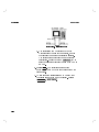
Notice
Hewlett-Packard to Agilent Technologies Transition
This documentation supports a product that previously shipped under the HewlettPackard company brand name. The brand name has now been changed to Agilent
Technologies. The two products are functionally identical, only our name has changed. The
document still includes references to Hewlett-Packard products, some of which have been
transitioned to Agilent Technologies.
Printed in USA
March 2000
front_IEC_1010.fm5
i Fri Oct 16 15:40:10 1998
HP 11758V Digital Radio Test System
User’s Guide
For use with HP 11758B and HP 8593E
HP Part No. 11758-90066
Printed in UK
September 1998
© Copyright Hewlett-Packard Ltd. 1998
front_IEC_1010.fm5
Notice
ii Fri Oct 16 15:40:10 1998
The information contained in this document is subject to change without notice.
Hewlett-Packard shall not be liable for errors contained herein or for incidental or
consequential damages in connection with the furnishing, performance, or use of this
material.
This document contains proprietary information which is protected by copyright. All
rights are reserved. No part of this document may be photocopied or reproduced
without the prior written consent of the manufacture, Hewlett-Packard Ltd.
© Copyright Hewlett-Packard Ltd. 1998.
All Rights Reserved. Reproduction, adaptation, or translation without prior written
permission is prohibited, except as allowed under the copyright laws. Station Road,
South Queensferry, Scotland, EH30 9TG, UK.
ii
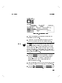
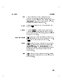
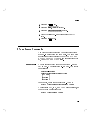
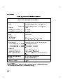
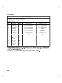
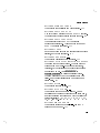
Contacting Agilent
By internet, phone, or fax, get assistance with all your test and measurement needs.
Table 1-1 Contacting Agilent
Online assistance: www.agilent.com/find/assist
United States
(tel) 1 800 452 4844
Latin America
(tel) (305) 269 7500
(fax) (305) 269 7599
Canada
(tel) 1 877 894 4414
(fax) (905) 282-6495
New Zealand
(tel) 0 800 738 378
(fax) (+64) 4 495 8950
Japan
(tel) (+81) 426 56 7832
(fax) (+81) 426 56 7840
Australia
(tel) 1 800 629 485
(fax) (+61) 3 9210 5947
Europe
(tel) (+31) 20 547 2323
(fax) (+31) 20 547 2390
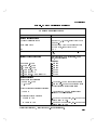
Asia Call Center Numbers
Country
Phone Number
Fax Number
Singapore
1-800-375-8100
(65) 836-0252
Malaysia
1-800-828-848
1-800-801664
Philippines
(632) 8426802
1-800-16510170 (PLDT
Subscriber Only)
(632) 8426809
1-800-16510288 (PLDT
Subscriber Only)
Thailand
(088) 226-008 (outside Bangkok)
(662) 661-3999 (within Bangkok)
(66) 1-661-3714
Hong Kong
800-930-871
(852) 2506 9233
Taiwan
0800-047-866
(886) 2 25456723
People’s Republic
of China
800-810-0189 (preferred)
10800-650-0021
10800-650-0121
India
1-600-11-2929
000-800-650-1101
2
Chapter 1
front_IEC_1010.fm5
iii Fri Oct 16 15:40:10 1998
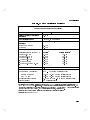
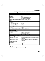
Warranty
Warranty
This Hewlett-Packard product is warranted against defects in materials and
workmanship for a period of one year from date of shipment. During the warranty
period, Hewlett-Packard Company will, at its option, either repair or replace products
which prove to be defective.
For warranty service or repair, this product must be returned to a service facility
designated by HP. Buyer shall prepay shipping charges to HP and HP shall pay
shipping charges to return the product to Buyer. However, Buyer shall pay all
shipping charges, duties, and taxes for products returned to HP from another country.
HP warrants that its software and firmware designated by HP for use with an
instrument will execute its programming instructions when properly installed on that
instrument. HP does not warrant that the operation of the instrument, or software, or
firmware will be uninterrupted or error free.
Limitation of Warranty
The foregoing warranty shall not apply to defects resulting from:
1
Improper or inadequate maintenance, adjustment, calibration, or operation by
Buyer;
2
Buyer-supplied software, hardware, interfacing or consumables;
3
Unauthorized modification or misuse;
4
Operation outside of the environmental and electrical specifications for the
product;
5
Improper site preparation and maintenance; or
6 Customer induced contamination or leaks.
THE WARANTY SET FORTH IS EXCLUSIVE AND NO OTHER WARRANTY,
WHETHER WRITTEN OR ORAL, IS EXPRESSED OR IMPLIED. HP
SPECIFICALLY DISCLAIMS THE IMPLIED WARRANTIES OF
MERCHANTABILITY AND FITNESS FOR A PARTICULAR PURPOSE.
iii
front_IEC_1010.fm5
iv Fri Oct 16 15:40:10 1998
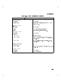
Exclusive Remedies
Exclusive Remedies
THE REMEDIES PROVIDED HEREIN ARE BUYER'S SOLE AND EXCLUSIVE
REMEDIES. HP SHALL NOT BE LIABLE FOR ANY DIRECT, INDIRECT,
SPECIAL, INCIDENTAL, OR CONSEQUENTIAL DAMAGES, WHETHER
BASED ON CONTRACT, TORT, OR ANY OTHER LEGAL THEORY.
Limitation of Remedies and Liability
THE REMEDIES PROVIDED HEREIN ARE BUYER'S SOLE AND EXCLUSIVE
REMEDIES. IN NO EVENT SHALL HP BE LIABLE FOR DIRECT, INDIRECT,
SPECIAL, INCIDENTAL, OR CONSEQUENTIAL DAMAGES (INCLUDING
LOSS OF PROFITS) WHETHER BASED ON CONTRACT, TORT OR ANY
OTHER LEGAL THEORY.
Certification
Hewlett-Packard Company certifies that this product met its published specifications
at the time of shipment from the factory. Hewlett-Packard further certifies that its
calibration measurements are traceable to the United States National Bureau of
Standards, to the extent allowed by the Bureau's calibration facility and to the
calibration facilities of other International Standards Organization members.
Restricted Rights Legend
Use, duplication, or disclosure by the government is subject to restrictions as set forth
in subdivision (b)(3)(ii) of the Rights in Technical Data and Computer Software
clause at 52.227-7013. Hewlett-Packard Company; 3000 Hanover Street; Palo Alto,
California 94304
Assistance
Product maintenance agreements and other customer assistance agreements are
available for Hewlett-Packard products.
iv
front_IEC_1010.fm5
v Fri Oct 16 15:40:10 1998
Sales and Service Offices
Sales and Service Offices
US FIELD OPERATIONS
Headquarters
California, Northern
California, Southern
Colorado
Hewlett-Packard Co.
19320 Pruneridge Ave.
Cupertino, CA 95014
(800) 752-0900
Hewlett-Packard Co.
301 E. Evelyn
Mountain View, CA 94041
(415) 694-2000
Hewlett-Packard Co.
1421 South Manhattan Ave.
Fullerton, CA 92631
(714) 999-6700
Hewlett-Packard Co.
24 Inverness Place, East
Englewood, CO 80112
(303) 649-5512
Atlanta Annex
Illinois
New Jersey
Texas
Hewlett-Packard Co.
2124 Barrett Park Drive
Kennesaw, GA 30144
(404) 648-0000
Hewlett-Packard Co.
5201 Tollview Drive
Rolling Meadows, IL 60008
(708) 255-9800
Hewlett-PackardCo.
150 Green Pond Rd.
Rockaway, NJ 07866
(201) 586-5400
Hewlett-Packard Co.
930 E. Campbell Rd.
Richardson, TX 75081
(214) 231-6101
EUROPEAN FIELD OPERATIONS
Headquarters
France
Germany
Great Britain
Hewlett-Packard S.A.
150, Route du Nant-d’Avril
1217 Meyrin 2/Geneva
Switzerland
(41 22) 780.8111
Hewlett-Packard France
1 Avenue Du Canada
Zone D’Activite De Courtaboeuf
F-91947 Les Ulis Cedex
France
(33 1) 69 82 60 60
Hewlett-Packard GmbH
Hewlett-Packard Strasse
61352 Bad Homburg v.d.H
Germany
(49 6172) 16-0
Hewlett-Packard Ltd.
Eskdale Road, Winnersh Triangle
Wokingham, Berkshire RG41 5DZ
England
(44 1734) 696622
INTERCON FIELD OPERATIONS
Headquarters
Australia
Canada
China
Hewlett-Packard Company
3495 Deer Creek Road
Palo Alto, California, USA
94304-1316
(415) 857-5027
Hewlett-Packard Australia Ltd.
31-41 Joseph Street
Blackburn, Victoria 3130
(61 3) 895-2895
Hewlett-Packard (Canada) Ltd.
17500 South ServiceRoad
Trans-Canada Highway
Kirkland, Quebec H9J 2X8
Canada
(514) 697-4232
China Hewlett-Packard Company
38 Bei San Huan X1 Road
Shuang Yu Shu
HaiDian District
Beijing, China
(86 1) 256-6888
Japan
Singapore
Taiwan
Hewlett-Packard Japan, Ltd.
1-27-15 Yabe, Sagamihara
Kanagawa 229, Japan
(81 427) 59-1311
Hewlett-Packard Singapore (Pte.)Ltd.
150 Beach Road
#29-00 Gateway West
Singapore 0718
(65) 291-9088
Hewlett-Packard Taiwan
8th Floor, H-PBuilding
337 Fu Hsing North Road
Taipei, Taiwan
(886 2) 712-0404
v
front_IEC_1010.fm5
vi Fri Oct 16 15:40:10 1998
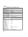
Declarations of Conformity
Declarations of Conformity
Declaration of Conformity
according to ISO/IEC Guide 22 and EN45014
Manufacturer’s Name:
Hewlett-Packard Ltd.
Manufacturer’s Address:
Queensferry Microwave Division
South Queensferry
West Lothian, EH30 9TG
Scotland, United Kingdom
Declares that the product
Product Name:
Model Number:
Product Options:
Digital Radio Test Set
HP 11758B
This declaration covers all options of the above product as detailed in
TCF A-5951-9852-02
Conforms with the protection requirements of European Council Directive 89/336/EEC on the approximation
of the laws of the member states relating to electromagnetic compatibility, against EMC test specifications
EN 55011:1991 (Group 1, Class A) and EN 50082-1:1992
Electromagnetic Compatibility (EMC)
As Detailed in:
Technical Construction File (TCF) No. A-5951-9852-02
DTI Appointed Competent Body
Assessed by:
EMC Test Centre,
GEC-Marconi Avionics Ltd.,
Maxwell Building,
Donibristle Industrial Park,
KY11 5LB
Scotland, United Kingdom
Technical Report Number:6893/2200/CBR, dated 23 September 1997
Supplementary Information:
The product conforms to the following safety standards:
EN 61010-1(1993) / IEC 1010-1(1990) +A1(1992) +A2(1994)
CSA-C22.2 No. 1010.1-93
EN 60825-1(1994) / IEC 825-1(1993)
The product herewith complies with the requirements of the Low Voltage Directive 73/23/EEC, and carries the CE
marking accordingly.
South Queensferry, Scotland
Location
01 October 1998
Date
R.M. Evans / Quality Manager
Europe Contact:
Your Local Hewlett-Packard Sales and Service Office or Hewlett-Packard GmbH, Department 2Q / Standards
Europe Herrenberger Strasse 130, D7030 Boblinger (Fax: +49-7031-143143)
vi
front_IEC_1010.fm5
vii Fri Oct 16 15:40:10 1998
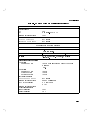
Declarations of Conformity
Declaration of Conformity
according to ISO/IEC Guide 22 and EN45014
Manufacturer’s Name:
Hewlett-Packard Ltd.
Manufacturer’s Address:
Queensferry Microwave Division
South Queensferry
West Lothian, EH30 9TG
Scotland, United Kingdom
Declares that the product
Product Name:
Model Number:
Product Options:
Digital Radio Test Set
HP 11758V
This declaration covers all options of the above product as detailed in
TCF A-5951-9852-02
Conforms with the protection requirements of European Council Directive 89/336/EEC on the approximation
of the laws of the member states relating to electromagnetic compatibility, against EMC test specifications
EN 55011:1991 (Group 1, Class A) and EN 50082-1:1992
Electromagnetic Compatibility (EMC)
As Detailed in:
Technical Construction File (TCF) No. A-5951-9852-02
DTI Appointed Competent Body
Assessed by:
EMC Test Centre,
GEC-Marconi Avionics Ltd.,
Maxwell Building,
Donibristle Industrial Park,
KY11 5LB
Scotland, United Kingdom
Technical Report Number:6893/2200/CBR, dated 23 September 1997
Supplementary Information:
The individual components of this product meet relevant international safety standards:
The product herewith complies with the requirements of the Low Voltage Directive 73/23/EEC, and carries the CE
marking accordingly.
South Queensferry, Scotland
Location
01 October 1998
Date
R.M. Evans / Quality Manager
Europe Contact:
Your Local Hewlett-Packard Sales and Service Office or Hewlett-Packard GmbH, Department 2Q / Standards
Europe Herrenberger Strasse 130, D7030 Boblinger (Fax: +49-7031-143143)
vii
front_IEC_1010.fm5
viii Fri Oct 16 15:40:10 1998
Statement of Compliance
Statement of Compliance
Electromagnetic
This product has been designed to meet the protection requirements of the European
Communities Electromagnetic Compatibility (EMC) directives:
Compatibility
(EMC) Information EN55011:1991 (Group 1, Class A)
EN50082-1:1992
- IEC 1000-4-2 (1995) ESD
- IEC 1000-4-3 (1995) Radiated Suseptibility
- IEC 1000-4-4 (1995) EFT
In order to preserve the EMC performance of the product, any cable which becomes
worn or damaged must be replaced with the same type and specification.
Safety Information This instrument has been designed and tested in accordance with publication
EN61010-1(1993) / IEC 1010-1(1990) +A1(1992) +A2(1994) / CSA C22.2 No.
1010.1(1993) Safety Requirements for Electrical Equipment for Measurement,
Control and Laboratory Use, and has been supplied in a safe condition. The
instruction documentation contains information and warnings which must be
followed by the user to ensure safe operation and to maintain the instrument in a
safe condition.
Noise Declaration
LpA<70dB
am Arbeitsplatz (operator position)
normaler Betrieb (normal position)
nach DIN 45635 pt.19 (per ISO 7779)
viii
front_IEC_1010.fm5
ix Fri Oct 16 15:40:10 1998
General Safety Information
General Safety Information
The following general safety precautions must be observed during all phases of
operation, service, and repair of this instrument. Failure to comply with these
precautions or with specific warnings elsewhere in this manual violates safety
standards of design, manufacture, and intended use of the instrument. HewlettPackard Company assumes no liability for the customer’s failure to comply with
these requirements.
WARNING
This is a Safety Class I instrument (provided with a protective earthing ground,
incorporated in the powercord). The mains plug shall only be inserted in a
socket outlet provided with a protective earth contact. Any interruption of the
protective conductor inside or outside of the instrument is likely to make the
instrument dangerous. Intentional interruption is prohibited.
DO NOT operate the product in an explosive atmosphere or in the presence of
flammable gasses or fumes.
DO NOT use repaired fuses or short-circuited fuseholders: For continued protection
against fire, replace the line fuse(s) only with fuse(s) of the same voltage and current
rating and type.
DO NOT perform procedures involving cover or shield removal unless you are
qualified to do so: Operating personnel must not remove equipment covers or
shields. Procedures involving the removal of covers and shields are for use by
service-trained personnel only.
DO NOT service or adjust alone: Under certain conditions, dangerous voltages may
exist even with the equipment switched off. To avoid dangerous electrical shock,
service personnel must not attempt internal service or adjustment unless another
person, capable of rendering first aid and resuscitation, is present.
DO NOT operate damaged equipment: Whenever it is possible that the safety
protection features built into this product have been impaired, either through
physical damage, excessive moisture, or any other reason, REMOVE POWER and
do not use the product until safe operation can be verified by service-trained
personnel. If necessary, return the product to a Hewlett-Packard Sales and Service
Office for service and repair to ensure the safety features are maintained.
DO NOT substitute parts or modify equipment: Because of the danger of
introducing additional hazards, do not install substitute parts or perform any
unauthorized modification to the product. Return the product to a Hewlett-Packard
Sales and Service Office for service and repair to ensure the safety features are
maintained.
ix
front_IEC_1010.fm5
x Fri Oct 16 15:40:10 1998
General Safety Information
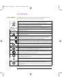
Safety Symbols
The following symbols on the instrument and in the manual indicate precautions
which must be taken to maintain safe operation of the instrument.
The Instruction Documentation Symbol. The product is marked with this symbol when it is
necessary for the user to refer to the instructions in the supplied documentation.
Indicates the field wiring terminal that must be connected to earth ground before operating
the equipment - protects against electrical shock in case of fault.
Frame or chassis ground terminal - typically connects to the equipment's metal frame.
Alternating current (AC)
Direct current (DC)
Indicates hazardous voltages
WARNING
Warning denotes a hazard. It calls attention to a procedure, which if not correctly
performed or adhered to could result in injury or loss of life. Do not proceed beyond a
warning note until the indicated conditions are fully understood and met.
CAUTION
Caution denotes a hazard. It calls attention to a procedure, which if not correctly
performed or adhered to could result in damage to or destruction of the instrument. Do not
proceed beyond a caution note until the indicated conditions are fully understood and met.
The CE mark shows that the product complies with all relevant European Legal Directives.
ISM 1-A
This is a symbol of an Industrial, Scientific, and Medical Group 1 Class A product.
The CSA mark is a registered trademark of the Canadian Standards Association, and
indicates compliance to the standards layed out by them.
The C-Tick mark is a registered trademark of the Spectrum Management Agency of Australia. This signifies compliance with the Australian EMC Framework Regulations under
the terms of the Radiocommunications Act of 1992.
This symbol indicates the position of the operating switch for ‘Off’ mode. NOTE: To
ensure instrument is isolated from mains, always rempve the appliance coupler (mains
power cord) from the power source.
This symbol indicates the position of the operating switch for ‘On’ mode.
This symbol indicates the position of the operating switch for ‘Stand-by’ mode. Note, the
instrument is NOT isolated from the mains when the switch is in this position.
To isolate the instrument, the mains coupler (mains input cord) should be removed from
the power supply.
x
Contents
1. General Information
Description . . . . . . . . . . .
Spectrum Analyzer . . . . . . .
HP 11758B Digital Radio Test Set
HP 11758V Option Information .
Accessory Kit . . . . . . . . .
Documentation . . . . . . . . . .
Standard Information . . . . . .
Option 915 Orders . . . . . . .
What is in these Manuals . . .
2. Installation and Verication
Introduction . . . . . . . . . .
Initial Inspection . . . . . . . .
Power Requirements . . . . . .
Power Requirements . . . . .
Line Voltage and Fuse Selection
Power Cables . . . . . . . .
Operating Environment . . . .
Operation . . . . . . . . . .
Environment . . . . . . . .
Physical . . . . . . . . . .
Cleaning . . . . . . . . . .
Rack Mounting . . . . . . .
Storage and Shipment . . . . .
Environment . . . . . . . .
Packaging . . . . . . . . .
Setting up the HP 11758V System
Backpanel Connections . . . .
Loading the Modes . . . . . .
.
.
.
.
.
.
.
.
.
.
.
.
.
.
.
.
.
.
.
.
.
.
.
.
.
.
.
.
.
.
.
.
.
.
.
.
1-1
1-4
1-7
1-8
1-9
1-12
1-12
1-14
1-14
.
.
.
.
.
.
.
.
.
.
.
.
.
.
.
.
.
.
.
.
.
.
.
.
.
.
.
.
.
.
.
.
.
.
.
.
2-1
2-2
2-3
2-3
2-4
2-6
2-8
2-8
2-8
2-8
2-8
2-9
2-9
2-9
2-9
2-11
2-11
2-12
Contents-1
Mode Loader . . . . . . . . . . .
Loading the Mode Loader . . . . .
Using the Mode Loader . . . . . .
Changing Modes and Presetting
Modes . . . . . . . . . . . .
Accessing the Main Menu of a Mode
Verifying the HP 11758V System . . . .
Introduction . . . . . . . . . . . .
Spectrum Analyzer Check . . . . . .
Power Meter Check . . . . . . . . .
Flatness Analyzer Check . . . . . . .
Multipath Fading Simulator Check . .
3 Tone Source Check . . . . . . . .
RF Source Check . . . . . . . . . .
Event Counter Check . . . . . . . .
Link Analyzer Check . . . . . . . .
3. Operation
Introduction . . . . . . . . . .
Operator's Maintenance . . . .
PRESET . . . . . . . . .
Radio Testing . . . . . . . . .
Group Delay (End-to-End Setup) .
Transmitter Setup . . . . .
Receiver Setup . . . . . . .
Group Delay (Loopback Setup) . .
Spectral Occupancy . . . . . . .
RF Output Power . . . . . . .
IF Output Power . . . . . . . .
IF Frequency Measurement . . .
Flatness through Upconverter . .
Flatness through Downconverter .
Intermodulation Distortion . . .
Antenna Return Loss . . . . . .
Susceptibility to Multipath Fading
Error Counting . . . . . . . . .
Instrument Operation . . . . . .
Multipath Fading Simulator . .
Contents-2
.
.
.
.
.
.
.
.
.
.
.
.
.
.
.
.
.
.
.
.
.
.
.
.
.
.
.
.
.
.
.
.
.
.
.
.
.
.
.
.
.
.
.
.
.
.
.
.
.
.
.
.
.
.
.
.
.
.
.
.
2-12
2-13
2-14
2-15
2-15
2-16
2-16
2-17
2-19
2-21
2-22
2-25
2-27
2-30
2-32
3-1
3-2
3-8
3-9
3-10
3-11
3-13
3-17
3-20
3-23
3-26
3-28
3-30
3-34
3-38
3-40
3-43
3-50
3-53
3-53
. . . . .
. . . . . . . .
Calibration Procedure . . .
Connection . . . . . .
Calibration Check . . .
Power Meter . . . . . . . .
Connection . . . . . . .
Preset . . . . . . . . . .
Zero . . . . . . . . . .
Calibration . . . . . . .
Power Level and Frequency
Power Measurement . . . .
3 Tone Source . . . . . . .
On/O . . . . . . . . .
Oset Frequency . . . . .
Total Power Out . . . . .
Readout . . . . . . . . .
Preset/Local . . . . . . .
Spectrum Analyzer . . . . .
Preset . . . . . . . . . .
Frequency . . . . . . . .
Span . . . . . . . . . .
Amplitude . . . . . . . .
Preselector Alignment . . .
CAL YTF . . . . . . . .
Marker . . . . . . . . .
Modes . . . . . . . . . .
Mode Loader . . . . . . .
Setting Date and Time . .
Digital Radio Mask Mode .
Link Analyzer . . . . . . .
Amplitude . . . . . . . .
Aux Ctrl . . . . . . . .
BW . . . . . . . . . . .
Cal . . . . . . . . . . .
Cong . . . . . . . . . .
Display . . . . . . . . .
Frequency and Span . . .
4PRESET/LOCAL5
4MORE5
.
.
.
.
.
.
.
.
.
.
.
.
.
.
.
.
.
.
.
.
.
.
.
.
.
.
.
.
.
.
.
.
.
.
.
.
.
.
.
.
.
.
.
.
.
.
.
.
.
.
.
.
.
.
.
.
.
.
.
.
.
.
.
.
.
.
.
.
.
.
.
.
.
.
.
.
.
.
.
.
.
.
.
.
.
.
.
.
.
.
.
.
.
.
.
.
.
.
.
.
.
.
.
.
.
.
.
.
.
.
.
.
.
.
.
.
.
.
.
.
.
.
.
.
.
.
.
.
.
.
.
.
.
.
.
.
.
.
.
.
.
.
.
.
.
.
.
.
.
.
.
.
.
.
.
.
.
.
.
.
.
.
.
.
.
.
.
.
.
.
.
.
.
.
.
.
.
.
.
.
.
.
.
.
.
.
.
.
.
.
3-53
3-53
3-54
3-54
3-56
3-56
3-56
3-57
3-57
3-58
3-58
3-59
3-60
3-60
3-60
3-61
3-61
3-61
3-62
3-62
3-62
3-62
3-63
3-63
3-64
3-65
3-65
3-66
3-69
3-70
3-70
3-71
3-71
3-71
3-71
3-72
3-72
3-72
Contents-3
Meas/User . . . . . . .
Mkr . . . . . . . . . .
Mode . . . . . . . . .
Preset . . . . . . . . .
Save and Recall . . . .
Trace . . . . . . . . .
Trig . . . . . . . . . .
Flatness Analyzer . . . . .
Flatness . . . . . . . .
Sources . . . . . . .
Calibration . . . . .
Measure . . . . . . .
Front Panel Hard Keys
Event Counter . . . . . .
Frequency Counter . . . .
Scalar Analyzer . . . . .
Source . . . . . . .
Calibration . . . . .
Measurement . . . . .
Front Panel Hard Keys
.
.
.
.
.
.
.
.
.
.
.
.
.
.
.
.
.
.
.
.
.
.
.
.
.
.
.
.
.
.
.
.
.
.
.
.
.
.
.
.
.
.
.
.
.
.
.
.
.
.
.
.
.
.
.
.
.
.
.
.
.
.
.
.
.
.
.
.
.
.
.
.
.
.
.
.
.
.
.
.
3-72
3-73
3-73
3-73
3-73
3-73
3-73
3-74
3-74
3-75
3-77
3-78
3-78
3-79
3-82
3-83
3-84
3-85
3-86
3-87
Hewlett-Packard Interface Bus . .
Where to Find HP-IB Information
HP-IB Address Selection . . .
3 Tone Source Commands . . . .
Power Level . . . . . . . . .
Frequency Oset . . . . . . .
Turning Tones ON/OFF . . . .
.
.
.
.
.
.
.
.
.
.
.
.
.
.
.
.
.
.
.
.
.
A-1
A-1
A-2
A-3
A-3
A-4
A-4
A. HP-IB
B. Specications
Contents-4
.
.
.
.
.
.
.
.
.
.
.
.
.
.
.
.
.
.
.
.
.
.
.
.
.
.
.
.
.
.
.
.
.
.
.
.
.
.
.
.
C. Error Messages
Error Messages . . . . . . . . . . . .
Spectrum Analyzer Error Messages . .
Power Meter Error Messages . . . . . .
Description . . . . . . . . . . . .
Errors 01 through 49 . . . . . . .
Errors 50 through 59 and 80 through
99 . . . . . . . . . . . . . .
Errors 60 through 79 . . . . . . .
Error Displays . . . . . . . . . . .
HP-IB Output Format . . . . . . .
Power Meter Error Messages . . . . .
C-1
C-1
C-10
C-10
C-10
C-10
C-10
C-10
C-11
C-11
Index
Contents-5
Figures
1-1.
1-2.
1-3.
2-1.
2-2.
2-3.
2-4.
2-5.
2-6.
2-7.
2-8.
2-9.
3-1.
3-2.
3-3.
3-4.
3-5.
3-6.
3-7.
3-8.
3-9.
3-10.
3-11.
Contents-6
HP 8593E E02 Spectrum Analyzer . .
HP 11758B Digital Radio Test Set . .
HP 11758V Option 301 Accessory Kit .
Line Voltage Selection . . . . . . . .
Power Cable and Line (Mains) Plug Part
Numbers . . . . . . . . . . . .
HP 11758V Backpanel Connections . .
Power Meter Verication Setup . . . .
Multipath Fading Simulator Check Setup
3 Tone Source Verication Check Setup
RF Source Verication Check Setup . .
Link Analyzer Verication Setup 1 . .
Link Analyzer Verication Setup 2 . .
HP 11758B Simplied Front Panel
Features (MPF Simulator) . . . .
HP 11758B Simplied Front Panel
Features (MPF Simulator) . . . .
HP 11758B Simplied Front Panel
Features (MPF Simulator and 3-Tone
Source) . . . . . . . . . . . . .
HP 11758B Simplied Front Panel
Features (Power Meter) . . . . .
HP 8593E Simplied Front Panel
Features . . . . . . . . . . . .
Link Transmitter Setup . . . . . . .
Link Receiver Setup . . . . . . . . .
Calibration Setup . . . . . . . . . .
Link Loopback Setup . . . . . . . .
Spectral Occupancy Setup . . . . . .
Display of Relative Mask . . . . . .
1-3
1-6
1-10
2-5
2-7
2-12
2-20
2-23
2-26
2-28
2-33
2-33
3-3
3-4
3-5
3-6
3-7
3-12
3-14
3-16
3-18
3-21
3-22
3-12.
3-13.
3-14.
3-15.
3-16.
3-17.
3-18.
3-19.
3-20.
3-21.
3-22.
3-23.
3-24.
3-25.
3-26.
Reference Calibration . . . . . . . .
RF Output Power Setup . . . . . . .
Calibration Setup . . . . . . . . . .
IF Output Power Setup . . . . . . .
IF Frequency Measurement . . . . .
Frequency Counter Display . . . . .
Flatness Calibration, 0 to 2.9 GHz . .
Flatness through Upconverter . . . .
Flatness Calibration, > 3 GHz . . . .
Flatness through Downconverter . . .
Predistortion Setup . . . . . . . . .
Return Loss Setup . . . . . . . . .
Susceptibility Measurement . . . . .
Event Counter Test Setup . . . . . .
Multipath Fading Simulator Calibration
Setup . . . . . . . . . . . . .
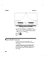
B-1. HP 8593E Dynamic Range . . . . . .
3-24
3-25
3-27
3-28
3-29
3-30
3-32
3-33
3-35
3-37
3-39
3-42
3-45
3-52
3-55
B-17
Contents-7
Tables
1-1.
3-1.
B-1.
B-2.
B-3.
C-2.
Contents-8
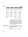
HP 11758V Standard Accessory Kit .
Attenuator & Adapter Combinations
HP 11758B Specications . . . . .
HP 8593E Specications . . . . . .
HP 8593E Option E02 Specications
Power Meter Error Messages . . . .
.
.
.
.
.
.
1-11
3-59
B-2
B-8
B-21
C-12
1
General Information
Description
The Hewlett-Packard 11758V Digital Radio Test System
is designed to test digital radios. It consists of the
HP 8593E E02 Spectrum Analyzer, the HP 11758B
Digital Radio Test Set and an optional Accessory Kit
(Option 301).
The HP 8593E E02 Spectrum Analyzer contains:
Microwave Spectrum Analyzer
IF Tracking Generator
Scalar Analyzer
Flatness Analyzer
Link Analyzer (Option 201)
IF Source
RF Source Control (Option 007)
Frequency Counter
Event Counter
Digital Radio Measurement Personality
The HP 11758B Digital Radio Test Set contains:
Power Meter
Three Tone Source
RF Source (Option 007)
Multipath Fading Simulator
Power Sensor
Crystal Detector
30 dB Reference Attenuator
50 Adaptor
Cables
1-1
General Information
HP 11758V
The Accessory Kit (Option 301) contains:
DADE Switch
IF Amplier
IF Return Loss Bridge
Attenuators
Cables
Adapters
SMA Wrench
1-2
HP 11758V
General Information
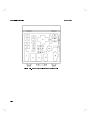
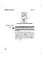
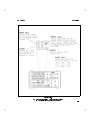
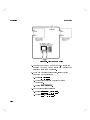
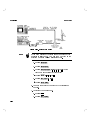
Figure 1-1. HP 8593E E02 Spectrum Analyzer
1-3
General Information
Spectrum Analyzer
1-4
HP 11758V
The HP 8593E E02 is a
programmable, preselected, portable microwave spectrum
analyzer with a frequency range of 9 kHz to 22 GHz.
Standard features include automatic calibration routines,
direct print and plot, trace storage, and a full set of
marker commands. The precision frequency timebase
and HP-IB interface are included in this system.
IF Tracking Generator/Scalar Analyzer. The IF
Tracking Generator is a 300 kHz to 2.9 GHz signal
generator. The signals generated by the Tracking
Generator track the input frequency of the Spectrum
Analyzer. The IF Tracking Generator is controlled by
the keys on the Spectrum Analyzer. Using the Tracking
Generator with the Spectrum Analyzer provides Scalar
Analysis capability.
Frequency Counter. The Frequency Counter is internal
to the Spectrum Analyzer. This function allows the user
to quickly make accurate frequency measurements with
the Spectrum Analyzer.
Event Counter. The Event Counter contains two fully
independent counters that can be used to count errors.
Both will count the number of occurrences, and one
of these also measures interval time. Threshold error
seconds can also be directly determined. The start
and stop times for the measurement are automatically
recorded and are shown along with the results on the
Spectrum Analyzer's display.
Flatness Analyzer. The Flatness Analyzer is a calibrated
detector with a frequency range of 10 MHz to 18 GHz.
This analyzer provides an accurate measurement of
small changes in amplitude response versus frequency.
Response in dB versus swept frequency is displayed on
the Spectrum Analyzer's display. Flatness analysis can
be made RF to IF, RF to RF, IF to RF and IF to IF.
Use of the Flatness Analyzer at RF frequencies requires
the RF Source in the HP 11758B.
Spectrum Analyzer.
HP 11758V
General Information
The Link Analyzer can be
used to measure the group delay and amplitude atness
characteristics of a radio. The measurements can be
made using two spectrum analyzers connected in an
end-to-end setup, or using one spectrum analyzer in a
loopback setup. When making end-to-end measurements,
the two spectrum analyzers may be located at dierent
stations, synchronized over a radio link, with one
analyzer being used as the transmitter and the other
as the receiver. In the loopback conguration, one
spectrum analyzer is used as both the transmitter and
receiver. The measurements are controlled using one of
the three link measurement personalities contained on
the DRTS ROM Measurement Card.
Link Analyzer (Option 201).
1-5
General Information
HP 11758V
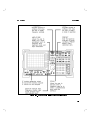
Figure 1-2. HP 11758B Digital Radio Test Set
1-6
HP 11758V
General Information
HP 11758B Digital Radio Test Set
The following equipment is part of the HP 11758B
Digital Radio Test Set.
RF Source (Option 007). The RF Source is a 3.5 GHz to
6.5 GHz source (with 10.7 GHz to 11.7 GHz frequency
extension if Option 011 is ordered with Option 007) that
is controlled by the softkeys of the Spectrum Analyzer.
The RF Source uses the Spectrum Analyzer's local
oscillator. The RF Source cannot be used independently
of the HP 8593E E02.
Power Meter. The Power Meter is similar to an
HP 437B Option H01; a programmable, single channel,
average power meter. It is used in combination with the
HP 8481D Power Sensor or the HP 8485D Power Sensor.
Calibrated adapters and xed attenuators are supplied
with the optional Accessory Kit (Option 301) to allow a
wide range of power level measurements in both 50
and
75
impedances.
3 Tone Source. The Three Tone Source consists of three
independent signal sources with highly stable output
levels. The output frequencies are 67, 70, and 75 MHz
(137, 140, and 145 MHz with Option 143). The sources
are adjustable in frequency (62.5 MHz) and level (25 dB
dynamic range) as a group. The sources can be turned
on and o independently.
Multipath Fading Simulator. The Multipath Fading
Simulator (similar to an HP 11757B) inserts a variable
notch lter in the IF of a receiver to simulate RF
propagation distortion of a microwave radio link.
This instrument is used to test the equalizer's ability
to function with calibrated amounts of propagation
distortion. The mathematical model used is the
Rummler Simplied Three Ray model. Notch depths to
40 dB at programmable frequencies are available with
1-7
General Information
HP 11758V
at fades to 50 dB (65 dB for fades without notches).
The design is optimized for dynamic swept simulations.
Sweeps can be made from a start frequency to a stop
frequency at a constant notch depth or from a start
notch depth to a stop notch depth at a constant
frequency. In addition, any combinations of notch depth,
frequency and attenuation can be swept simultaneously
between any arbitrary start and stop settings. High
sweep rates are possible of up to 400 dB per second
and 600 MHz per second. The Multipath Fading
Simulator can be calibrated to the Spectrum Analyzer
and Tracking Generator for optimum accuracy.
HP 11758V Option Information
Options on the System
007
011
140
147
201
270
301
908
909
915
916
H04
H07
H08
H10
H13
K01
1-8
Add 3.5 06.475 GHz RF Source
Add 10.7 011.7 GHz source
140 MHz (only) Fading Simulator and
Intermodulation Test Source
70 & 140 MHz Fading Simulator and 70 MHz
(only) Intermodulation Test Source
Link Analyzer for Group Delay and Amplitude
Flatness Measurements
Spectrum Analyzer Frequency Extension to
26.5 GHz
Accessory Kit
Rack Mount Kits without Handles
Rack Mount Kits with Handles
Service package.
Additional Operating manual.
Fader High Power Input/Output Capability
Add 6.0 08.0 GHz source
Add 7.0 010.0 GHz source
Add 9.5 013.0 GHz source
Add 6.0 013.0 GHz source
Soft backpack cases (2)
HP 11758V
Accessory Kit
General Information
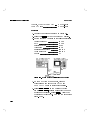
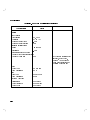
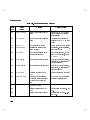
The following table lists the components included in the
Option 301 Accessory Kit. This kit contains many of
the required components, adapters and cables necessary
to use the Digital Radio Test System. If you want to
inventory your case, compare the slots in the gure
with the items mentioned in the following table. Some
items, such as the HP 11708A Reference Attenuator, are
included with the standard HP 11758V DRTS rather
than the Option 301 Accessory Kit. These parts are
labelled (Standard) in the table, and have a slot in
the accessory kit box where they can be stored. Other
items, such as the 11758-60002 Levelling Head, are only
included with certain options of the HP 11758V DRTS.
These parts are labelled in the table with the option
number concerned.
The items listed in the table with no Slot Number,
are included in the Accessory Kit but are stored in a
separate compartment.
1-9
General Information
HP 11758V
Figure 1-3. HP 11758V Option 301 Accessory Kit
1-10
HP 11758V
Slot #
1,2,3,4
5
6
7
8
9
10
11
12
13
14
15
16
17,18
19
20,21
22
23
24
25
26,27
28
29
30
1
2
General Information
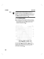
Table 1-1. HP 11758V Standard Accessory Kit
Part Description
Part Number
RF Source Filters (Options 007, H07, H08,
Depends on Option
H10, H13)
External Leveling Head
11758-60002
30 dB Reference Attenuator (Standard)
11708A
30 dB 18 GHz Attenuator
8491B Opt 030
20 dB 18 GHz Attenuator
8491B Opt 020
50
Nm0Nm
1250-0778
50
Nf0Nf
1250-0777
75
BNCf0BNCf
1250-1287
DRTS ROM Card
11768-80010
32K RAM Card
85700A
30 dB Power Attenuator
8498A Opt 030
50/75
Minimum Loss Pad
11852B
Transformer 50
Nm075
BNCf
9100-4859
Nm0BNCf (Standard)
1250-0780
APC-3.5f0Nm (Option 270)
1250-1744
50
Nf0SMAm
1250-2273
DADE Switch
11766A
Power Sensor (Standard/Option 270)
8481D /8485D
Return Loss Bridge
11769A
Crystal Detector (Standard)
8470B Opt 012
50/75
Matching Pad
11981A
Wrench Combination 5/16 in
8720-0015
Right Angle Nm0Nf
1250-2281
Tracking Generator Amplier
11767A
Cable, Nm0Nm 6 ft
11500A
Cable, 75
BNC 6 ft
11758-60022
Cable, 75
BNC 10 ft
11758-60023
Cable, 75
BNC 15 ft
11758-60024
1
2
Qty
Varies
1
1
1
1
1
1
1
1
1
1
1
1
2
1
2
1
1
1
1
2
1
1
1
1
2
1
1
Supplied with Standard 11758V
Supplied with 11758V Option 270. Substituted for 8481D.
1-11
General Information
Documentation
Note
Standard Information
1-12
HP 11758V
HP 11758V documentation consists of Operating
information, Programming information, and Service
information. Service information can be obtained when
selecting Option 915. Any manual can be ordered from
the HP Sales and Service Oces listed inside the rear
cover of this manual.
Field Operation HP 11758V documentation is
modular. This allows you to choose, from the extensive
documentation HP provides, the kind of information
you wish to carry into the eld. The recommended eld
operation documentation is:
HP 11758V User's Guide.
HP 11757B Multi-Simulator User's Guide.
\Local Reference" section from the HP 11757B
Multipath Fading Simulator Operation and
Programming Reference.
HP 11770A Link Measurement Personality User's
Guide.
C/N Vs BER DLP Measurement Personality User's
Guide.
M-Curve DLP Measurement Personality User's Guide.
Standard operating information is shipped with the
instrument. Option 916 provides an additional set of
operating information. You should have received the
following documentation with your instrument:
HP 11758V User's Guide.
HP 11758T/U Calibration Guide.
HP 11757B Multi-path Fading Simulator User's Guide.
HP 11757B Installation and Calibration Guide.
HP 11758V
General Information
HP 11757B Support Disk.
HP 11757B Multipath Fading Simulator Operation
and Programming Reference.
HP 437B Operation Manual.
C/N Vs BER DLP Measurement Personality User's
Guide.
ROM Measurement Card.
M-Curve DLP Measurement Personality User's Guide.
HP 8590 Series Operation.
HP 8593E Quick Reference Guide.
HP 8590 Series Spectrum Analyzer Programming
Manual.
HP 8593E Calibration Guide.
HP 11770A Link Measurement Personality User's
Guide.
HP 85713A Digital Radio Measurements Personality
Operating Guide.
HP 8593E EO2/E04 Supplement.
HP 859X Firmware Note.
HP 859X Cover Letter.
Option 915 Orders
If you ordered an option 915, the following manuals were
also sent.
HP 11758T/U Calibration Guide.
HP 11758T/U Service Manual.
HP 11758T/U CLIPS.
HP 11757B Installation and Calibration Guide.
HP 11757B Support Disk.
1-13
General Information
HP 11758V
HP 11757B Service Manual.
HP 11757B CLIPS.
HP 437B Service Manual.
HP 8593E Service Manual.
HP 8593E Component Level Information.
HP 8593E E02/E04 Supplement.
What is in these Manuals
Contains system operating
information for the entire HP 11758V Digital Radio
Test System.
HP 11758T/U Calibration Guide Contains system
performance tests and adjustments.
Making Measurements with the HP 11757B explains
how to make signature measurements with the
Multipath Fading Simulator part of the HP 11758V
(the signature capability does not exist with option
001 orders).
HP 11758V User's Guide
HP 11757B Installation and Calibration Guide
contains information about conducting automated
performance tests and adjustments using the HP
11757B Support Disk.
HP 11757B Support Disk An HP-Basic program to
perform automated performance tests and adjustments
over HP-IB.
HP 11757B Operating and Programming Manual
contains installation, verication, operating, and
programming information about the Multipath Fading
Simulator part of the HP 11758V.
HP 437B Operating Manual contains operating and
programming information about the Power Meter part
of the HP 11758V.
1-14
HP 11758V
General Information
describes how to use a DLP (Down
Loadable Program) to make Carrier to Noise versus
Bit Error Ratio measurements.
M-Curve DLP Manual describes how to use a DLP
(Down Loadable Program) to display M-Curve
measurement results on the spectrum analyzer display.
HP 8590 Series Operation contains general operating
information about the spectrum analyzer.
HP 8593E Quick Reference Guide is a quick reference
to the spectrum analyzer.
HP 8590 Series Programming Manual contains HP-IB
programming information for the spectrum analyzer.
HP 8593E Calibration Guide contains calibration and
performance verication information for the HP 8593E
Spectrum Analyzer.
Addendum to Calibration Guides contains regulatory
information for the HP 8593E Spectrum Analyzer.
C/N DLP Manual
HP 11770A Link Measurement Personality User's
Guide contains detailed information on making group
delay and amplitude atness measurements using the
HP 11770A Link Measurement Personality with the
HP 8593E Option E02 Spectrum Analyzer.
HP 85713A Digital Radio Measurements Personality
Guide contains information on how to use the
downloadable programs shipped with the HP 11758V.
HP 8593E E02/E04 Supplement contains operating,
verication, and service information about the
spectrum analyzer that is specic to the E02 and E04
options.
Firmware Note gives rmware revision details for the
HP 8593E Spectrum Analyzer.
HP 11758T/U Service Manual contains service
information for the DRTS system.
1-15
General Information
HP 11758V
contains schematics, material
lists, and component location diagrams for the DRTS
system.
HP 11757B Service Manual contains service
information for the Multipath Fading simulator part of
the HP 11758V.
HP 11757B CLIPS contains schematics, material lists,
and component location diagrams for the Multipath
Fading simulator part of the HP 11758V.
HP 437B Service Manual contains service information
for the Power Meter part of the HP 11758V.
HP 8593E Service Manual contains service information
for the Spectrum Analyzer part of the HP 11758V.
HP 8593E CLIPS contains schematics, material lists,
and component location diagrams for the Spectrum
Analyzer part of the HP 11758V.
HP 11758T/U CLIPS
1-16
2
Installation and Verification
Introduction
This section provides the information needed to
install and verify the HP 11758V. Included is
information pertinent to initial inspection, power
requirements, line voltage selection, power cables,
interconnection, environment, instrument mounting,
storage, and shipment. To make measurements, the
relevant measurement mode must be loaded from
the HP 11768-80010 ROM Measurement Card. The
procedure for this is discussed later in this section. Also
included in this section are procedures for verication of
operation of the instruments in the Digital Radio Test
System.
2-1
Installation and Verification
HP 11758V
Initial Inspection
Warning
To avoid hazardous electrical shock, do not turn on the
instrument when there are signs of shipping damage to
any part of the outer enclosure (covers or panels).
Inspect the shipping container for damage. If the
shipping container or cushioning material is damaged, it
should be kept until the contents of the shipment have
been checked for completeness and the instrument has
been checked mechanically and electrically. The contents
of the shipment should be as shown in Figure 1-1
and Figure 1-2. Procedures for checking electrical
performance are given in the service manual. If the
contents are incomplete, if there is mechanical damage or
defect, or if the instrument does not pass the electrical
performance tests, notify the nearest Hewlett-Packard
oce. If the shipping container is damaged, or the
cushioning material shows signs of unusual stress, notify
the carrier as well as the Hewlett-Packard oce. Keep
the shipping materials for the carrier's inspection.
2-2
HP 11758V
Installation and Verification
Power Requirements
Note
Power Requirements
Caution
The following Power Requirements are for mains
connected equipment unless stated other wise.
Operating Voltage Range:115/230V
Operating Frequency Range: 50-60Hz
Power Dissipation: 200 VA (max).
Before switching on this instrument, make sure that the
line voltage selctor switch is set to the voltage of the
power supply and the correct fuse is installed. Ensure
the power supply voltage is in the specied range.
Mains supply voltage should not exceed 610%
of the nominal selected line voltage.
Warning
Appliance coupler (mains input powercord) is the
disconnect device. Do not position the instrument such
that access to the coupler is impaired.
For continued protection against fire hazard,
replace the line fuse only with the same type and line
rating F5A 250V. The use of other fuses or materials is
prohibited.
If this instrument is not used as specified, the
protection provided by the equipment could be impaired.
This instrument must be used in a normal condition only
(in which all means for protection are intact).
No operator serviceable parts inside. Refer
servicing to qualified personnel. To prevent electrical
shock do not remove covers.
2-3
Installation and Verification
HP 11758V
Line Voltage and
Fuse Selection
Caution
BEFORE PLUGGING THIS INSTRUMENT into the
line (Mains) voltage, you must set the rear-panel voltage
selector switch to correspond to the power source.
An improper selector switch setting can damage the
instrument when it is turned on.
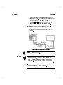
Set both instruments' rear-panel voltage selector
switches to the line voltage range (115V or 230V)
corresponding to the available AC voltage. See
Figure 2-1. Insert a small screwdriver or similar tool
in the slot and slide the switch up or down so that the
proper voltage label is visible.
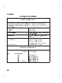
Note
The AC line input fuse is the same value for both the
HP 11758B and the HP 8593E, regardless of the input
line voltage.
Fuse Ratings and Part Numbers
Line Voltage
115V
230V
Rating
F5.0A, 250V
F5.0A, 250V
Part Number
2110-0756
2110-0756
The line fuse is housed in a small container immediately
above the rear-panel power connector. The container
provides space for storing a spare fuse. To check the
fuse, insert the tip of a screwdriver in the slot at the
bottom of the container and pry gently to remove the
container.
2-4
HP 11758V
Installation and Verification
Note
The fuses are not attached to the container and will drop
out.
If the fuse is mechanically defective or missing, install a
new fuse in the proper position and reinsert the fuse
container.
Figure 2-1. Line Voltage Selection
2-5
Installation and Verification
HP 11758V
Power Cables
Warning
Caution
Cooling
2-6
BEFORE CONNECTING EITHER INSTRUMENT, the
protective earth terminals of this instrument must be
connected to the protective conductor of the line (Mains)
power cable. The line plug shall only be inserted in a
socket outlet provided with a protective earth contact.
The protective action must not be negated by the use
of an extension cord (power cable) without a protective
conductor (grounding). Grounding one conductor of a two
conductor outlet is not sufficient protection.
Failure to ground the instrument chassis (that is, using a
two-pronged adapter on the line (Mains) power cable)
will result in the output amplier's increased sensitivity
to damage by static discharge.
Both instruments are equipped with a three-wire
power cable. When connected to an appropriate AC
power receptacle, this cable grounds the instrument
cabinet. The type of power cable plug shipped with each
instrument depends on the country of destination. See
Figure 2-2, \Power Cable and Line (Mains) Plug Part
Numbers", for the part numbers of these power cables.
Cables are available in dierent lengths and some with
right angle plugs to the instrument. Check with your
nearest HP service center for descriptions and part
numbers for these cables.
To provide adequate cooling, an air gap of approximately
75mm should be maintained around the instrument.
HP 11758V
Installation and Verification
Figure 2-2. Power Cable and Line (Mains) Plug Part Numbers
2-7
Installation and Verification
HP 11758V
Operating Environment
Caution
Operation
This instrument is designed for indoor use only.
The instrument may be operated at temperatures from
0 C to +55 C at altitudes up to 4600m (15,000 ft.).
The instrument may be operated in environments up
to 95% relative humidity to 40C, but it should be
protected from temperature extremes which may cause
condensation.
The instrument is designed for use in
Istallation Category II and Pollution Degree 2 per
IEC1010 and 64 respectively.
Environment
0 C to +55 C.
Up to <95% Relative Humidity
to 40C.
. . . . . . . . . . . . . Meets EN55011:1991 (Group1,
Class A), and EN50082-1:1992.
Temperature: . . . . . .
Humidity: . . . . . . . . .
EMC:
Physical
Weight:
10.0 kg (22.0 lb) nominal
Dimensions (height x width x depth): 163H x 476W x
468D mm nominal (incl. handle).
Both instrument cabinets have an adjustable handle
that can be used as a stand for convenience in bench
operation. The handle can be folded back to ensure
self-aligning of instruments when stacked.
Cleaning
Use a soft, clean damp cloth to clean the front-panel and
side covers.
2-8
HP 11758V
Installation and Verification
Rack Mounting
Warning
The HP 11758B weighs 10.0 kg (22.0 lb), and the
HP 8593E weighs 15.9 kg (35.0 lb). Care must be
exercised when lifting to avoid personal injury. Use
equipment slides when rack mounting.
Rack mounting information is provided with the rack
mounting kits. If the kits were not ordered with the
instrument as options, they may be ordered through the
nearest Hewlett-Packard oce. Refer to \Mechanical
Options" in Chapter 1 for information regarding rack
mounting kits.
Storage and Shipment
Environment
The instrument should be stored in a clean, dry
environment. The following environmental limitations
apply to both storage and shipment:
Temperature . . . . . . 040C to +75C
Humidity . . . . . . . . . <95% relative at 15C to 40C
Altitude . . . . . . . . . . <15 000 meters (49 200 feet)
Packaging
Tagging for Service. If the instrument is being returned
to Hewlett-Packard for service, please complete one of
the blue repair tags located at the end of this manual
and attach it to the instrument.
To minimize repair time, be as specic as possible when
describing the failure. Keep the following two items in
mind when describing the failure:
1. Describe what makes you think the instrument is
failing. An example might be \Power Meter displays
2-9
Installation and Verification
HP 11758V
NO SENSOR when a power sensor is connected to the
input port".
2. If the failure only occurs under certain conditions,
explain how to duplicate the failure. An example
might be \After pressing the LINE switch three times,
the instrument will not power up".
Original Packaging. Containers and materials identical
to those used in factory packaging are available
through Hewlett-Packard oces. Mark the container
\FRAGILE" to encourage careful handling. In any
correspondence, refer to the instrument by model
number and full serial number.
Other Packaging. The following general instructions
should be used for repackaging with commercially
available materials.
1. Wrap the instrument in heavy paper or plastic. If
shipping to a Hewlett-Packard oce or service center,
complete one of the blue tags mentioned above and
attach it to the instrument.
2. Use a strong shipping container. A double-wall carton
made of 2.4 MPa(350 psi) test material is adequate.
3. Use enough shock-absorbing material (75 to 100 mm
layer; 3 to 4 inches) around all sides of the instrument
to provide a rm cushion and prevent movement
in the container. Protect the front panel with an
appropriate type of cushioning material to prevent
damage during shipment.
4. Seal the shipping container securely.
5. Mark the shipping container \FRAGILE" to
encourage careful handling.
2-10
HP 11758V
Installation and Verification
Setting up the
HP 11758V System
The appropriate system conguration depends upon the
measurement you want to make. Radio Testing, found in
section 3, describes the setup for several of the tests this
system is capable of performing.
When setting up the system for measurements there are
some backpanel connections standard for most tests.
After you make the following connections, you should use
the Mode Loader to congure the HP 8593E for use in
the Digital Radio Test System.
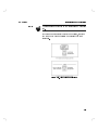
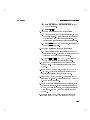
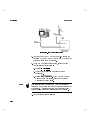
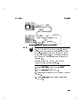
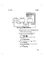
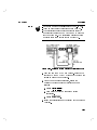
Backpanel Connections
1. Connect the AUX Interface on the HP 11758B to
the AUX Interface on the HP 8593E using cable
8120-5343.
2. Connect the HP-IB port on the HP 11758B to the
HP-IB port on the HP 8593E.
3. If your DRTS system includes an RF Source (Option
007), connect the LO OUT on the HP 8593E to
the LO IN on the HP 11758B using an RF cable
(HP 8120-4948).
4. Check the backpanel of the HP 8593E to conrm that
the EXT REF IN is connected to the 10 MHZ REF
OUTPUT.
5. Check Figure 2-3 and compare with your connections.
2-11
Installation and Verification
HP 11758V
Figure 2-3. HP 11758V Backpanel Connections
Loading the Modes
Note
You must load appropriate modes from the DRTS mode
card before making measurements with this system.
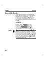
Mode Loader
The Mode Loader utility provides a convenient way to
automatically dispose of and load the various modes that
are provided on the HP 11768-80010 ROM Measurement
Card. The total memory size required for these modes
is larger than the user memory in the HP 8593E, so it
is necessary to load the Modes in smaller groups. While
this may be done manually, it is faster and easier to use
the Mode Loader.
2-12
HP 11758V
Installation and Verification
Loading the Mode Loader
1. Press 4 5 to bring up the Mode Menu. Alternate
presses of the 4 5 key will switch between the
Main Menu of the current mode and the Mode
Menu.
MODE
MODE
Note
The Mode Menu always has
rst softkey.
NNNNNNNNNNNNNNNNNNNNNNNNNNNNNNNNNNNNNNNNNNNNNNNNNNNNN
SPECTRUM ANALYZER
as the
2. If SPECTRUM ANALYZER is the only softkey displayed
on the Mode Menu, then skip to step number 8.
3. If MODE LOADER is one of the softkeys, then this
utility is already loaded in the Spectrum Analyzer
and the rest of this procedure may be skipped. See
\Using the MODE LOADER".
4. If other Modes are present on these softkeys they
should be disposed of before loading in the MODE
LOADER by doing:
5. Press 4
5. Press MORE 1 of 2 .
6. Press DISPOSE USER MEM (an \IF YOU ARE
SURE . . . " message appears).
7. Press DISPOSE USER MEM for a second time.
8. To load the MODE LOADER do the following:
9. Insert the ROM Measurement Card
(HP 11768-80010) in to the card reader on the front
panel of the HP 8593E Spectrum Analyzer.
10. Press 4
5.
11. Select the memory card by pressing INTRNL CRD to
underline CRD.
12. Press CATALOG CARD .
NNNNNNNNNNNNNNNNNNNNNNNNNNNNNNNNNNNNNNNNNNNNNNNNNNNNN
NNNNNNNNNNNNNNNNNNNNNNNNNNNNNNNNNNN
NNNNNNNNNNNNNNNNNNNNNNNNNNNNNNNNNNN
CONFIG.
NNNNNNNNNNNNNNNNNNNNNNNNNNNNNNNNNNNNNNNNNNNNNNNNNN
NNNNNNNNNNNNNNNNNNNNNNNNNNNNNNNNNNNNNNNNNNNNNNNNNN
RECALL
NNNNNNNNNNNNNNNNNNNNNNNNNNNNNNNN
NNNNNNNNNNNNNNNNNNNNNNNNNNNNNNNNNNNNNN
2-13
Installation and Verification
HP 11758V
13. Press CATALOG ALL . The le \dLOADME" will be
highlighted.
14. Press LOAD FILE which loads the highlighted le.
15. MODE LOADER should now be one of the keys on the
Mode Menu.
16. If a user Down-Loadable Program (DLP) is to be
used in conjunction with the Event Counter mode, it
should be loaded in before the Event Counter mode
is loaded.
NNNNNNNNNNNNNNNNNNNNNNNNNNNNNNNNNNN
NNNNNNNNNNNNNNNNNNNNNNNNNNNNN
NNNNNNNNNNNNNNNNNNNNNNNNNNNNNNNNNNN
Using the Mode Loader
1. Insert the Digital Radio Test System ROM
Measurement Card (HP 11768-80010) in to the card
reader on the front panel of the HP 8593E, if not
already inserted.
Note
The Mode Menu always has
rst softkey.
NNNNNNNNNNNNNNNNNNNNNNNNNNNNNNNNNNNNNNNNNNNNNNNNNNNNN
SPECTRUM ANALYZER
as the
2. Press 4 5 to bring up the Mode Menu.
( MODE LOADER should be the second softkey.)
3. Press MODE LOADER .
MODE
NNNNNNNNNNNNNNNNNNNNNNNNNNNNNNNNNNN
NNNNNNNNNNNNNNNNNNNNNNNNNNNNNNNNNNN
4. Items 1 to 12 can be selected by using the DATA keys
to enter the item number and pressing 4
5. Press
NEXT PAGE to access items 13 to 16. It will take 10
to 60 seconds to dispose of the current modes and
load in the new ones.
When an item number is selected, the Mode Loader rst
disposes of any other DRTS modes that are resident
in the HP 8593E memory, before loading in the new
mode(s). If the Multipath DLP is selected (item number
11), the Mode Loader will also delete itself. However,
ENTER
NNNNNNNNNNNNNNNNNNNNNNNNNNNNN
Note
2-14
HP 11758V
Installation and Verification
user dened DLP's will not be disposed (provided that
the guidelines for assigning names and keys for user
DLP's were followed | as contained in the HP 8590
Series Spectrum Analyzer Programming Manual ).
Changing Modes and Presetting Modes
1. Once the mode is loaded, a softkey for that mode will
appear in the Mode Menu. Press 4 5 to display
the Mode Menu and then press the softkey for that
mode you want to use. If a mode is reentered it will
be in the same state as when it was left, provided
4
5 has not been pushed.
2. To return to the Spectrum Analyzer mode, press
4
5 to bring up the Mode Menu and then
SPECTRUM ANALYZER . The Spectrum Analyzer will be
returned to the same state as when it was left.
3. The green 4
5 key may be used to take the
instrument back to the Spectrum Analyzer mode,
but this will also preset the instrument, including all
modes, to the default state.
MODE
PRESET
MODE
NNNNNNNNNNNNNNNNNNNNNNNNNNNNNNNNNNNNNNNNNNNNNNNNNNNNN
PRESET
Note
The green 4
5 key should seldom need to be used.
It is not necessary to press 4
5 before switching to
another mode.
PRESET
PRESET
4. An individual mode may be preset to its default state
without aecting other modes by use of the mode
PRESET softkey that is in the Main Menu of that
mode.
NNNNNNNNNNNNNNNNNNNN
Accessing the Main Menu of a Mode
1. Press 4
2. Or press 4
5
MODE
and then the mode name softkey.
5 4
5.
MODE
MODE
2-15
Installation and Verification
HP 11758V
Verifying the
HP 11758V System
Introduction
Note
The following procedure is intended to test the
functionality of the HP 11758V Digital Radio Test
System without using external test equipment.
Successful completion of this procedure indicates that
all major features of the Test System are functioning.
This procedure, however, does not test to performance
specications. To test performance specications,
refer to the HP 11758T/U Calibration Guide (part
number listed under Documentation in Chapter 1 of this
manual).
Performing the verication check is recommended
after installation of the system, when a failure in the
HP 11758V is suspected or any time condence in the
system needs to be reestablished. If a failure of the
HP 11758V has occurred, this procedure will determine
which instrument (HP 8593E, HP 11758B or Option 301
Accessory Kit) needs to be returned to Hewlett-Packard
for service.
The sequence in which these checks are run is critical for
accurate troubleshooting.
The functional check is comprised of the following tests:
Spectrum Analyzer Check
Perform the amplitude and frequency auto calibration
routines.
Power Meter Check
Zero the Power Sensor and check the Power Reference
and Oset function.
2-16
HP 11758V
Installation and Verification
Flatness Analyzer Check
Checks a atness calibration for repeatability.
Multipath Fading Simulator Check
Checks the functionality of the notch lter.
3 Tone Source Check
Display the 3 Tones on the 8593E Spectrum Analyzer.
RF Source Check
If your system has an RF Source (Option 007), this
test will measure the power level of the output signal.
Event Counter Check
Checks the accuracy of the event counter and interval
counter readings.
Link Analyzer Check
Checks the main functions of the group delay and
amplitude atness measurements capability.
Spectrum Analyzer Check
Description
The HP 8593E internal frequency and amplitude
calibration routines are run and a condence test is
performed. This procedure will exercise all the major
Spectrum Analyzer functions and return a message
should any problems be encountered. This check takes
approximately 15 minutes to run.
If either calibration routine or the condence test
fail to run successfully, there may be a problem with
the Spectrum Analyzer. This check is internal to the
Spectrum Analyzer and is independent of HP 11758B
functionality. If this test fails, return the Spectrum
Analyzer to HP for servicing.
Procedure
1. Connect a 50
coaxial cable (such as HP 10503A)
between the front panel CAL OUT and the
2-17
Installation and Verification
HP 11758V
INPUT 50
connectors (you will need an Nm-BNCf
adaptor).
2. Perform the frequency and amplitude calibration
routine by pressing 4 5 and CAL FREQ & AMPTD .
During the frequency routine, CAL:SWEEP,
CAL:FREQ, and CAL:SPAN are displayed as the
sequence progresses. During the amplitude routine,
CAL:AMPTD, CAL:3 dB BW, CAL:ATTEN,
and CAL:LOGAMP are displayed as the sequence
progresses. CAL:DONE appears when the routine is
completed. Any failures or discrepancies produce a
message on the screen. See appendix C of this manual
for error messages.
3. If desired, when the frequency and amplitude
calibration routines have been completed successfully,
store the data by pressing CAL STORE .
The calibration routines calibrate the analyzer by
generating correction factors. The softkey CAL STORE
stores the calibration correction factors in the area of
analyzer memory accessed at power up. The analyzer
will automatically apply these factors in future
measurements, even if the analyzer has been turned
o.
4. Perform a condence test by pressing 4 5,
MORE 1 OF 3 , and CONF TEST .
The analyzer performs a self test of several major
functions. The test is performed within one to two
minutes. If the unit does not function properly, a
message appears on the screen. See Chapter 3 in the
HP 8593E Service Manual for an explanation of the
message.
When the calibration routines have been completed
successfully, the analyzer is ready for normal
operation.
NNNNNNNNNNNNNNNNNNNNNNNNNNNNNNNNNNNNNNNNNNNNNNNNNN
CAL
NNNNNNNNNNNNNNNNNNNNNNNNNNNNN
NNNNNNNNNNNNNNNNNNNNNNNNNNNNN
CAL
NNNNNNNNNNNNNNNNNNNNNNNNNNNNNNNNNNN
2-18
NNNNNNNNNNNNNNNNNNNNNNNNNNNNN
HP 11758V
Power Meter Check
Installation and Verification
The functions of the Power Meter are checked using
power sensors and sensor cables. These checks provide
reasonable assurance that most of the front panel
controlled functions are being executed by the Power
Meter.
1. Turn on the Power Meter and observe the power up
routine with no power sensor connected to the input.
During power up the diagnostics stored in ROM are
executed under microprocessor control and turn on
all the display segments and annunciators.
When the self-test is nished, the Power Meter will
display \SELF TEST OK". It will then display \NO
SENSOR".
If an error occurs during the power-up tests,
the Power Meter will display an error code. For
information about the specic error, refer to \Error
Messages" in Appendix A in the HP 437B Operating
Manual .
2. Press 4
5, then 4
5.
3. Zero the sensor:
a. Connect the power sensor to the power meter
using the HP 11730B power sensor cable.
b. Disconnect the power sensor from any power
sources.
c. Press 4 5. The power meter will display
\ZEROING *****". When zeroing is nished,
this message will disappear.
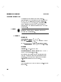
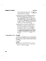
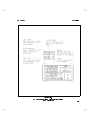
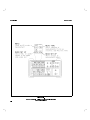
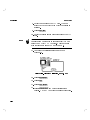
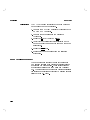
4. Calibrate the sensor:
a. Set up the power meter as shown in Figure 2-4.
PRESET/LOCAL
ENTER
ZERO
2-19
Installation and Verification
HP 11758V
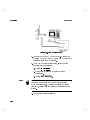
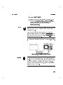
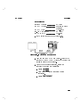
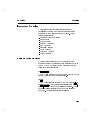
Figure 2-4. Power Meter Verification Setup
Caution
Always use the 30 dB reference attenuator when
calibrating the power meter with the HP 8481D Power
Sensor (or HP 8485D if your system has Option 270).
b. Press 4 5 4 5 (CAL). The power meter will
display the reference calibration factor (Ref Cal
Factor) that is currently set.
c. Examine the power sensor to determine the
required Ref Cal Factor.
d. Use the arrow keys if required, to enter this value
into the power meter, then press 4
5.
e. The power meter will display \CAL *****".
When the calibration is nished, this message will
disappear.
5. Enter the oset factor for the attenuators:
a. Check the labels of the attenuators used, to nd
the oset factors. These values are dependent on
the frequency at which you are measuring. Add
together the oset factors of all the attenuators.
b. Press 4
5 on the power meter, then enter the
combined oset factor.
6. Enter the calibration factor for the sensor:
SHIFT
ZERO
ENTER
OFFSET
2-20
HP 11758V
Installation and Verification
a. Check the label of the power sensor to nd the
calibration factor. This value is dependent on the
frequency at which you are measuring.
b. Press 4 5 4 5 (CAL FAC), then use the
arrow keys to enter the calibration factor.
Press 4 5 475 (PWR REF). The PWR REF
annunciator will be enabled.
The Power Meter will display
030.00 dBm, 60.02 dBm.
Press the 4
5 key to display dBm.
Press the 4
5 key. The display will read \OFS
+00.00 dB."
Using the arrow keys modify the display to read
\OFS +30.00 dB."
Press the 4
5 key.
The Power Meter will display 0.00 dBm 60.02 dBm.
SHIFT
7.
8.
9.
10.
11.
12.
13.
Flatness Analyzer Check
FREQ
SHIFT
dBm/W
OFFSET
ENTER
Description
The HP 8470B Crystal Detector is used to measure the
swept output of the IF Tracking Generator (mode of
HP 8593E). The level and stability of that measurement
are checked.
Procedure
1. Press the 4 5 key on the HP 8593E Spectrum
Analyzer. Press the FLATNESS & SOURCES softkey.
If Flatness and Sources has not been loaded, insert
the DRTS Measurement Card into the mode loader
and press MODE LOADER 4 5 4
5.
2. Connect the BNC end of the HP 8470B Crystal
Detector to the Detector Input on the rear panel
MODE
NNNNNNNNNNNNNNNNNNNNNNNNNNNNNNNNNNNNNNNNNNNNNNNNNNNNNNNN
NNNNNNNNNNNNNNNNNNNNNNNNNNNNNNNNNNN
4
ENTER
2-21
Installation and Verification
HP 11758V
of the HP 8593E using a BNC cable. Connect the
Type N end of the Detector to the RF OUT 50
connector on the HP 8593E front panel.
3. Press: Sources
4. Press: SOURCE IF RF so that IF is underlined.
5. Press: CENTER FREQ , then enter a center frequency
of 1.5 GHz.
6. Press: SPAN , then enter a span of 1 GHz.
7. Press: SRC PWR , and set the source power to 0 dBm.
NNNNNNNNNNNNNNNNNNNNNNN
NNNNNNNNNNNNNNNNNNNNNNNNNNNNNNNNNNNNNN
NNNNNNNNNNNNNNNNNNNNNNNNNNNNNNNNNNN
NNNNNNNNNNNNNN
NNNNNNNNNNNNNNNNNNNNNNN
8. Select a Scale Log (amplitude) of 0.1 dB/div.
9. Normalize the trace by pressing 4 5, CAL TRANS ,
STORE THRU .
10. A normal trace would be very at, with no sharp
spikes, noise or deviations that are greater than
2 minor divisions. If your trace is not what is to
be expected, check your connections for tightness,
reconnect the detector if necessary, and press the
CAL TRANS softkey again.
NNNNNNNNNNNNNNNNNNNNNNNNNNNNN
CAL
NNNNNNNNNNNNNNNNNNNNNNNNNNNNNNNN
NNNNNNNNNNNNNNNNNNNNNNNNNNNNN
Multipath Fading Simulator Check
Description
This check runs the main functions of the Multipath
Fading Simulator. The HP 8593E is used as a spectrum
analyzer to check the functionality of the notch lter of
the MFS.
Equipment
Spectrum Analyzer . . . . . . . . . . . . . .
50
-75
Matching Pad (2) . . . . . . .
Adapter, Type N(m) to BNC(f) . . .
75
BNC Cable (2) . . . . . . . . . . . . .
2-22
HP 8593E
HP 11981A
HP 1250-0780
HP 8120-3616
HP 11758V
Installation and Verification
Procedure
1. Connect the equipment as shown in Figure 2-5. Note
that all cables are 75
.
Figure 2-5. Multipath Fading Simulator Check Setup
2. Set the HP 8593E for use as a spectrum analyzer.
a. Press: SPECTRUM ANALYZER
b. Press: PRESET SPECTRUM
NNNNNNNNNNNNNNNNNNNNNNNNNNNNNNNNNNNNNNNNNNNNNNNNNNNNN
NNNNNNNNNNNNNNNNNNNNNNNNNNNNNNNNNNNNNNNNNNNNNNN
3. If your Multipath Fader is congured for 70 MHz
band, set up the spectrum analyzer for a span from
40 to 100 MHz. On the spectrum analyzer:
a. Press: START FREQ
b. Press: 4 5 4 5 4 5
c. Press: STOP FREQ
d. Press: 4 5 4 5 4 5 4 5
4. Turn on the RF Output of the spectrum analyzer.
a. Press: 4 5
b. Press: 4
5
c. Press: TRACK GEN
NNNNNNNNNNNNNNNNNNNNNNNNNNNNNNNN
4
0
MHZ
NNNNNNNNNNNNNNNNNNNNNNNNNNNNN
1
0
0
MHZ
MKR
AUX CTRL
NNNNNNNNNNNNNNNNNNNNNNNNNNNNN
2-23
Installation and Verification
HP 11758V
d. Press: SRC PWR ON (you may have to push twice
to get ON underscored)
e. Press: 4 5 4 5 40 5
Now set the Multipath Fading Simulator for a notch
sweep:
a. Press: 4
5
b. The frequency display will blink. Use the arrow
keys to display 40.0, then press 4
5
c. The depth display will blink. Use the arrow keys
to display 20.0, then press 4
5
d. The attenuator display will blink. Use the arrow
keys to display 00.0, then press 4
5
e. Press: 4
5
f. The frequency display will blink. Use the arrow
keys to display 100.0, then press 4
5
g. The depth display will blink. Use the arrow keys
to display 20.0, then press 4
5
h. The attenuator display will blink. Use the arrow
keys to display 00.0, then press 4
5
Set the time for the sweep. Press: 4 5 4
5
(SET TIME). Use the arrow keys to set the sweep
for 3 seconds. Press: 4
5
Start the sweep. Press: 4 5 4
5 (SWP
ALL)
Observe the spectrum analyzer display. You
should observe a notch sweeping across from 40 to
100 MHz. The notch stays at 20 dB and the at fade
attenuation at 0 dB.
To stop the sweeping press: 4 5 4
5
again.
NNNNNNNNNNNNNNNNNNNNNNNNNNNNNNNN
1
5.
0
dBm
SET START
ENTER
ENTER
ENTER
SET STOP
ENTER
ENTER
ENTER
6.
SHIFT
SET STOP
ENTER
7.
8.
9.
2-24
SHIFT
SET START
SHIFT
SET START
HP 11758V
Installation and Verification
10. Set the notch frequency to 70 MHz. Press:
4
5 and use the arrow keys to set the
display to 70.0, press 4
5.
11. Check the notch to see if it is at 70 MHz.
a. Press: 4 5
b. Press: MKR!MIN
c. Verify that the frequency of the marker is
70 MHz.
12. Check that the notch is of 20 dB depth:
a. Press: MARKER DELTA
b. Press: 4
5, then enter 0 dB. Read the
Marker Delta value in the upper right corner of
the spectrum analyzer display and verify that it
reads 20 dB 6 1 dB.
13. Zero the marker. Press: 4 5 MARKER DELTA .
14. Set the at fade attenuation to 10 dB. Press:
4
5, and use the arrow keys to set the display to
read 10.0, then press 4
5.
15. Read the marker delta in the upper right corner
of the spectrum analyzer display. It should read
010 dB 61 dB.
NOTCH FREQ
ENTER
MKR
NNNNNNNNNNNNNNNNNNNNNNNNNN
NNNNNNNNNNNNNNNNNNNNNNNNNNNNNNNNNNNNNN
NOTCH DEPTH
NNNNNNNNNNNNNNNNNNNNNNNNNNNNNNNNNNNNNN
MKR
ATTEN
ENTER
3 Tone Source Check
Description
This check looks at the output of the 3 Tone Source on
the HP 8593E Spectrum Analyzer. The frequencies and
approximate level of the 3 Tones are checked. This check
tests the HP 11758B, and for troubleshooting purposes is
completely independent of the HP 8593E.
Equipment
50
-75
Matching Pad . . . . . . . . . . HP 11981A
2-25
Installation and Verification
HP 11758V
Adapter, Type N(m) to BNC(f) . . . HP 1250-0780
75
BNC Cable . . . . . . . . . . . . . . . . . HP 8120-3616
Procedure
1. Connect the equipment as shown in Figure 2-6.
2. Press the 4
5 key on the Spectrum Analyzer.
3. Set the Spectrum Analyzer to the following settings:
Center Frequency . . . . . . . . . . . . 70 MHz
SPAN . . . . . . . . . . . . . . . . . . . . . . . 25 MHz
Reference Level . . . . . . . . . . . . . . 0 dBm
Attenuator . . . . . . . . . . . . . . . . . . 20 dB
Resolution Bandwidth . . . . . . . . 100 kHz
Video Bandwidth . . . . . . . . . . . . 300 kHz
Marker . . . . . . . . . . . . . . . . . . . . . . ON
PRESET
Figure 2-6. 3 Tone Source Verification Check Setup
4. On the HP 11758B 3 Tone Source, turn all
three tones on and set both the LEVEL and
FREQUENCY knobs to their center position.
5. Press 4 5 4
5 on the Multipath Fading
Simulator keyboard. Press 8 or 9 until 3 TONE READ
appears on the display. Press 4
5. Verify that
the frequency oset is 61.0 MHz and the power level
reads -8 dBm.
SHIFT
PRESET
ENTER
2-26
HP 11758V
Installation and Verification
6. Observe the 3 Tone Spectrum on the Spectrum
Analyzer. Using the marker, verify the frequencies
of the 3 Tones. They should be 67, 70 and 75 MHz
Look for a level of approximately 011 dBm per tone.
7. Rotate the FREQUENCY knob on the 3 Tone
Source. All 3 tones should vary in frequency as
the knob is rotated. Return the knob to its center
position.
8. Rotate the LEVEL knob. All 3 tones should vary in
level as the knob is rotated. Return the knob to its
center position.
9. Look at spurious signals emanating from the 3 Tone
Source. Check that they are at least 60 dB below
the 3 Tones.
10. Turn o each of the 3 Tones in sequence and ensure
that they decrease in amplitude at least 40 dB when
turned o.
11. If the 3 Tone Source fails any of the above tests,
return the HP 11758B Digital Radio Test System to
Hewlett-Packard for servicing.
RF Source Check
Description
This check should be made if your system has an RF
Source (Option 007). The check ensures that the RF
Source is outputting sucient power and that it covers
the appropriate frequency range. The RF Source is
dependent on both the HP 11758B Digital Radio Test
Set and the HP 8593E Spectrum Analyzer. The RF
Source output is measured using the Power Meter.
Equipment
Power Sensor . . . . . . . . . . HP 8481D (or HP 8485D)
30 dB Attenuator . . . . . . HP 8491A Opt. 030
Leveling Head . . . . . . . . . HP 11758-60002
2-27
Installation and Verification
HP 11758V
Figure 2-7. RF Source Verification Check Setup
Procedure
1. Connect the equipment as shown in Figure 2-7.
2. Using the Mode Loader, load the Flatness and
Sources menu from the DRTS Measurement Card.
a. Press: 4 5
b. Press: MODE LOADER
c. Press: 4 5 4
5, then wait for the program to
load.
d. Press: FLATNESS & SOURCES
3. Using the SOURCES menu (in Flatness & Sources
mode) on the HP 8593E, select SOURCE RF . Then
set the CENTER FREQ to 6.4 GHz, the SPAN to 0,
and the SRC PWR to 0 dBm.
a. Press: SOURCES
b. Press the SOURCE IF RF softkey so that RF is
underscored.
c. Press: CENTER FREQ 4 5 4 5 4 5 4 5
d. Press: ZERO SPAN
MODE
NNNNNNNNNNNNNNNNNNNNNNNNNNNNNNNNNNN
4
ENTER
NNNNNNNNNNNNNNNNNNNNNNNNNNNNNNNNNNNNNNNNNNNNNNNNNNNNNNNN
NNNNNNNNNNNNNNNNNNNNNNN
NNNNNNNNNNNNNNNNNNNNNNNNNNNNN
NNNNNNNNNNNNNNNNNNNNNNN
NNNNNNNNNNNNNNNNNNNNNNNNNNNNNNNNNNNNNN
NNNNNNNNNNNNNNNNNNNNNNNNNNNNNNNNNNN
6
NNNNNNNNNNNNNNNNNNNNNNNNNNNNN
2-28
.
4
GHz
HP 11758V
Installation and Verification
e. Press: SRC PWR and SCR PWR ON OFF so that
ON is underscored.
f. Press: 4 5 4 5
Enter the oset factor for the attenuators:
a. Check the labels of the attenuators used, to nd
the oset factors. These values are dependent on
the frequency at which you are measuring. Add
together the oset factors of all the attenuators.
b. Press 4
5 on the power meter, then enter the
combined oset factor.
Enter the calibration factor for the sensor:
a. Check the label of the power sensor to nd the
calibration factor. This value is dependent on the
frequency at which you are measuring.
b. Press 4 5 4 5 (CAL FAC), then use the
arrow keys to enter the calibration factor.
Read the RF Source output power level on the
Power Meter. The power level should read 0 dBm
62 dB.
From the SOURCES menu, change SRC PWR to
010 dBm. Verify that the output level of the RF
Source has decreased approximately 10 dB.
Set the SRC PWR to 0 dBm. Change the output
frequency to 3.5 GHz. Repeat steps 3 and 4 for the
3.5 GHz output frequency.
If the RF Source passes all the above criteria, it is
functioning correctly. If the power level is good at
0 dBm, but does not change, or changes incorrectly
when set to 010 dBm, then the fault is in the HP
11758B.
If power is low in any case, disconnect the cable
between the HP 11758B RF Source LEVELING
NNNNNNNNNNNNNNNNNNNNNNN
0
4.
NNNNNNNNNNNNNNNNNNNNNNNNNNNNNNNNNNNNNNNNNNNN
dBm
OFFSET
5.
SHIFT
6.
7.
8.
9.
10.
FREQ
2-29
Installation and Verification
HP 11758V
INPUT and the LEVELING HEAD (11758-60017).
If the power level now increases to > +5 dBm, then
the fault is in the HP 11758B.
11. If the cause of the problem is still undetermined,
measure the signal at the HP 8593E's 1ST LO
OUTPUT. Measure this signal at the end of the
cable that connects to the HP 11758B, so that the
cable is checked also. The level of this signal must
be > 010 dBm. If this level is low check it again at
the 1ST LO OUTPUT in order to determine if the
cable or the HP 8593E is the problem.
12. If the cause of the problem is still undetermined,
disconnect the LEVELING HEAD from the
HP 11758B and measure the power coming out
of the HP 11758B's RF OUTPUT port. If this
power level is > +5 dBm then the LEVELING
HEAD is the problem and it should be returned to
Hewlett-Packard for service. If the power level is
< +5 dBm then the problem is in the HP 11758B
and it should be returned to Hewlett-Packard for
service.
Event Counter Check
Description
The Spectrum Analyzer's HIGH SWEEP output is used
as a stimulus for the event counter and interval counter
inputs. The event counter and interval counter readings
are checked.
Procedure
1. Connect a BNC cable between the HIGH SWEEP
IN/OUT and EVENT CNTR INPUT jacks on the
Spectrum Analyzer rear panel.
2-30
HP 11758V
Installation and Verification
2. On the Spectrum Analyzer, press:
a. 4
5
b. Insert the DRTS Measurement Card in the mode
loader.
c. 4 5
d. MODE LOADER
e. 4 5 4
5
f. EVENT COUNTER
g. More 1 of 2
h. DSPLY SA ON OFF (set to ON)
PRESET
MODE
NNNNNNNNNNNNNNNNNNNNNNNNNNNNNNNNNNN
5
ENTER
NNNNNNNNNNNNNNNNNNNNNNNNNNNNNNNNNNNNNNNNN
NNNNNNNNNNNNNNNNNNNNNNNNNNNNNNNNNNN
NNNNNNNNNNNNNNNNNNNNNNNNNNNNNNNNNNNNNNNNNNNNNNN
i. 4 5
j. ZERO SPAN
k. 4
5, 4 5 4 5 4 5
3. After a few seconds, the EVENT CNTR display
should read a count of approximately 10. A variation
of 62 counts between gate periods is normal.
4. Connect a BNC cable between the HIGH SWEEP
IN/OUT and INTERVAL CNTR INPUT jacks on the
rear panel.
5. After a few seconds, the INTERVAL CNTR display
should read a count of approximately 10 and a time of
approximately 0.800 seconds.
SPAN
NNNNNNNNNNNNNNNNNNNNNNNNNNNNN
SWEEP
2
0
ms
2-31
Installation and Verification
Link Analyzer Check
HP 11758V
The performance of the link analyzer can be checked
using the Group Delay Verication mode. This mode
consists of a series of condence test routines which
check the main functions of the link analyzer.
If the link analyzer is faulty, the condence tests will
return an error message. Take a note of the error
message and return the analyzer to HP for servicing.
Procedure
1. Ensure that the HP 8593E Spectrum Analyzer is
calibrated and is functioning correctly. Refer to
Chapter 8 of the HP 8590 Series Spectrum Analyzer
User's Guide for details on how to calibrate the
spectrum analyzer and check for basic problems.
2. On the Spectrum Analyzer, press:
a. 4
5
b. Insert the DRTS Measurement Card in the mode
loader.
c. 4 5
d. MODE LOADER
e. 4 5 4 5 4
5
f. GRP DLY VERIFY .
3. Start the rst set of tests as follows:
a. Press VERIFY CARD .
b. A drawing of the analyzer will appear on the
screen, prompting you to connect CAL OUT to
INPUT.
PRESET
MODE
NNNNNNNNNNNNNNNNNNNNNNNNNNNNNNNNNNN
1
6
ENTER
NNNNNNNNNNNNNNNNNNNNNNNNNNNNNNNNNNNNNNNNNNNN
NNNNNNNNNNNNNNNNNNNNNNNNNNNNNNNNNNN
2-32
HP 11758V
Installation and Verification
Figure 2-8. Link Analyzer Verification Setup 1
c. Make the connections shown and press CONTINUE .
This will start the rst set of tests which will last
approximately 30 seconds.
4. You will then be prompted to connect the OUTPUT
to INPUT.
NNNNNNNNNNNNNNNNNNNNNNNNNN
Figure 2-9. Link Analyzer Verification Setup 2
a. Make the connections shown and press CONTINUE .
This will start the second set of tests which will
last approximately 30 seconds.
b. If no error is found, the message NO ERROR FOUND
will appear on the screen. Press OK . This will
return you to the Group Delay Verication mode
main menu.
5. To exit the Group Delay Verication mode, press
DISPOSE VERIFY twice.
NNNNNNNNNNNNNNNNNNNNNNNNNN
NNNNNNNN
NNNNNNNNNNNNNNNNNNNNNNNNNNNNNNNNNNNNNNNNNNNN
2-33
Installation and Verification
2-34 This Page Intentionally Left Blank
HP 11758V
3
Operation
Introduction
This chapter provides operating information for the
HP 11758V Digital Radio Test System. This chapter is
separated into two parts:
Radio Testing
The \Radio Testing" section shows the user how
to make specic radio receiver and transmitter
measurements using the Digital Radio Test Set.
Operation
The \Operation" section provides more detailed
descriptions of the functions of the HP 11758V
System.
Neither of these sections provides an in-depth discussion
of all of the features of the HP 11758V. The purpose
of both of these sections is to help the user become
familiar with the HP 11758V System and begin making
measurements in the minimum amount of time. For
more detailed information, see the Operating and Service
Manuals for the individual instruments in the Service
Package of the HP 11758V.
3-1
Operation
HP 11758V
Operator's Maintenance
Warning
For continued protection against fire hazard, replace the
line fuse with a fuse of the same rating only. Do not use
repaired fuses or short-circuited fuse holders.
Operator's maintenance consists of replacing defective
fuses. The primary power fuse is located within the
Line Power Module Assembly. Refer to Chapter 2,
\Installation and Verication", for instructions on how
to change the fuse.
If the instrument does not operate properly and is
being returned to Hewlett-Packard for service, please
complete one of the blue tags located at the end of
this manual and attach it to the instrument. Refer to
Chapter 2, \Installation and Verication", for packaging
instructions.
The following pages contain gures introducing the user
to front panel features of the Digital Radio Test Set.
3-2
HP 11758V
Operation
Figure 3-1.
HP 11758B Simplified Front Panel Features
(MPF Simulator)
3-3
Operation
3-4
HP 11758V
Figure 3-2.
HP 11758B Simplified Front Panel Features
(MPF Simulator)
HP 11758V
Operation
Figure 3-3.
HP 11758B Simplified Front Panel Features
(MPF Simulator and 3-Tone Source)
3-5
Operation
3-6
HP 11758V
Figure 3-4.
HP 11758B Simplified Front Panel Features
(Power Meter)
HP 11758V
Operation
Figure 3-5. HP 8593E Simplified Front Panel Features
3-7
Operation
HP 11758V
Caution
Note
Ensure that the instrument is set for the proper power
line voltage. Check the position of the voltage selector
switches on the rear panels of the instruments. See
Chapter 2, \Installation and Verication", for more
information before proceeding.
Allow 1/2 hour warm-up time for maximum accuracy.
PRESET
The PRESET function sets the instruments in the
Digital Radio Test System to a known state. It is good
practice to PRESET each instrument at the beginning of
each measurement session.
1. Press the 4
5 key on the Multipath Fading
Simulator.
2. Press the 4
5 key on the Multipath Fading
Simulator.
3. Press the 4
5 key on the Power Meter.
4. Press the 4
5 key on the Power Meter.
5. Press the 4
5 key on the Spectrum Analyzer.
PRESET/LOCAL
ENTER
PRESET/LOCAL
ENTER
PRESET
Caution
3-8
When measuring power levels above +30 dBm with the
spectrum analyzer, use a 30 dB high power attenuator to
avoid damage. A suitable attenuator is the HP 8498A
Option 030 which is available with the Option 301
Accessory Kit.
HP 11758V
Radio Testing
Operation
The HP 11758V Digital Radio Test System has the
capability of meeting many standard test requirements.
This section has procedures for the following tests:
Group Delay (End-to-End Setup)
Group Delay (Loopback Setup)
Spectral Occupancy
RF Output Power
IF Output Power
IF Frequency Measurement
Flatness through Upconverter
Flatness through Downconverter
Intermodulation Distortion
Antenna Return Loss
Susceptibility to Multipath Fading
Error Counting
In addition, you may use the HP 11758V to make the
following tests:
Transmitter Tests:
Local Oscillator Frequency
Local Oscillator Power
Coupler Calibration
ALC Range
IF slope (atness)
TWT Intermodulation distortion
Predistorter Intermodulation distortion
Modulator output level
Power spectral density measurements
IF Return Loss
Receiver Tests:
Local Oscillator Frequency
Local Oscillator Power
Receive Input Level
IF slope (atness)
IF Signal level
3-9
Operation
HP 11758V
Signal to Interference susceptibility
Adaptive Slope Equalizer Performance
Transversal Equalizer Performance
Attenuator Calibration
Composite Fade Margin
(thermal+dispersive+interference)
Terminal Tests:
Frame and Clock Frequency
Carrier Frequency
Signal to Interference susceptibility
Transversal Equalizer Performance
Note
The tests that follow assume that you have already
set up your Digital Radio Test System, and have
familiarized yourself with the Mode Loader. For details
on using the mode loader, refer to the \Setting Up the
HP 11758V System" in Chapter 2.
Group Delay
(End-to-End Setup)
This test uses the Link Transmitter mode and Link
Receiver mode to measure the group delay and
amplitude atness of a digital microwave radio link. The
test requires two HP 8593E Spectrum Analyzers, one
located at the transmitter and the other at the receiver.
The HP 8593E Spectrum Analyzers must be tted
with the Group Delay and Amplitude Flatness card
(HP 8593E Option E02). The group delay capability can
be ordered with a new DRTS (HP 11758V Option 201),
a stand-alone spectrum analyzer (HP 859XE
Option E02), or as a retrot (HP 11768A).
3-10
HP 11758V
Operation
The real-time group delay and amplitude responses
can be displayed on the receiving analyzer's screen,
enabling the radio receiver to be adjusted for optimum
performance.
All the parameters used in this test can be changed to
customize the test as required.
Test Equipment
Spectrum Analyzers (2) . . . . . . .
75
BNC Cables (2) . . . . . . . . . .
50
-75
Matching Pad (2) . . . .
50
Nm to BNCf (2) . . . . . . . . .
HP 8593E Opt. E02
11758-60022
HP 11981A
1250-0780
Transmitter Setup
The following procedure describes how the spectrum
analyzer should be setup at the transmitter station. If
you are at the receiver station, refer to the Receiver
Setup procedure.
1. Connect the HP 8593E Spectrum Analyzer as shown
in Figure 3-6.
3-11
Operation
HP 11758V
Figure 3-6. Link Transmitter Setup
2. Load and run the DRTS Mode Loader. Refer to the
\Setting Up the HP 11758V System" in Chapter 2 for
details on using the mode loader.
3. When the mode loader is running, select the Link
Transmitter mode as follows:
a. Press: 4 5 4 5 4
5
b. Wait until the program has loaded before
continuing.
c. Press: LINK TRANSMTR . The TX Setup Window
will appear on the screen, showing the default
measurement parameters.
1
4
ENTER
NNNNNNNNNNNNNNNNNNNNNNNNNNNNNNNNNNNNNNNNN
Note
It is essential that the Frequency Span and Baseband
Frequency must be set to the same values as those set at
the receiver. This also applies to the center frequency,
unless there is a frequency translation in the system.
4. Set the parameters as follows:
3-12
HP 11758V
Operation
a. Press:
b. Press:
c. Press:
,
,
,
4FREQUENCY5
250 kHz .
4AUX
,
5
CTRL
BB FREQ , MORE 1 of 2 ,
NNNNNNNNNNNNNNNNNNNNNNN
SRC PWR ,
NNNNNNNNNNNNNNNNNNNNNNN
NNNNNNNNNNNNNNNNNNNNNNNNNNNNNNNNNNN
. Press
405 4dBm5
so that ON is underlined.
e. Check that the parameters shown in the TX
SETUP WINDOW are as required, and are the
same as those set at the receiver.
The matching pad shown in Figure 3-6 has a power
loss of approximately 5.7 dB. Remember to take this
into account when choosing the output power from the
spectrum analyzer.
NNNNNNNNNNNNNNNNNNNNNNN
SRC PWR
Note
.
4SPAN5 445 405 4MHZ5
NNNNNNNNNNNNNNNNNNNNNNNNNN
d. Press:
.
4FREQUENCY5 475 405 4MHZ5
Receiver Setup
The following procedure describes how the spectrum
analyzer should be setup at the receiver station. If you
are at the transmitter station, refer to the Transmitter
Setup procedure.
1. Connect the HP 8593E Spectrum Analyzer as shown
in Figure 3-7.
3-13
Operation
HP 11758V
Figure 3-7. Link Receiver Setup
2. Load and run the DRTS Mode Loader. Refer to the
\Setting Up the HP 11758V System" in Chapter 2 for
details on using the mode loader.
3. When the mode loader is running, select the Link
Receiver mode as follows:
a. Press: 4 5 4 5 4
5
b. Wait until the program has loaded before
continuing.
c. Press: LINK RECEIVER .
1
5
ENTER
NNNNNNNNNNNNNNNNNNNNNNNNNNNNNNNNNNNNNNNNN
Note
It is essential that the Frequency Span and Baseband
Frequency must be set to the same values as those
set at the transmitter. This also applies to the center
frequency, unless there is a frequency translation in the
system.
4. Set the parameters as follows:
3-14
HP 11758V
Operation
a. Ensure that the message Receiver Unlocked is
shown on the HP 8593E display. If it is not, press
4
5 so that it appears.
b. Press: 4
5, 4 5 4 5 4
5.
c. Press: 4 5, 4 5 4 5 4 5.
d. Press: 4
5, BB FREQ , MORE 1 of 2 ,
250 kHz .
e. Press: 4
5, SET INP LEVEL . This step
sets the internal attenuation of the analyzer to a
suitable level.
5. Before any measurements are made, the receiver may
need to be calibrated. This should be performed
if the message Frequency Uncal is shown on the
display.
a. Press: 4 5, CAL ALL .
b. The analyzer will prompt you to connect RF
OUT to INPUT. This connection should be made
using any hardware that will be used in the actual
test (with the exception of the DUT). Figure 3-8
shows the spectrum analyzer connected with the
matching pads and the same cables that will be
used in the test.
Although only one matching pad will be used in the
actual test, both of the pads shown in Figure 3-8 should
be used for the calibration, to avoid an impedance
mismatch. However, any unatness in the matching pad
will cause a slight inaccuracy in the calibration.
TRIG
FREQUENCY
SPAN
4
7
0
0
MHZ
MHZ
NNNNNNNNNNNNNNNNNNNNNNN
NNNNNNNNNNNNNNNNNNNNNNNNNNNNNNNNNNN
FREQUENCY
NNNNNNNNNNNNNNNNNNNNNNNNNN
NNNNNNNNNNNNNNNNNNNNNNNNNNNNNNNNNNNNNNNNN
AMPLITUDE
NNNNNNNNNNNNNNNNNNNNNNN
CAL
Note
3-15
Operation
HP 11758V
Figure 3-8. Calibration Setup
c. The calibration can be performed over the
whole frequency range of the analyzer, or over
the frequency range that is currently selected.
The latter option provides the most accurate
calibration. Press the bottom CONTINUE key to
select a calibration frequency range of 50 MHz to
90 MHz.
6. Press: 4 5. The receiving analyzer will
automatically lock up to the swept signal from the
transmitter.
7. At this stage the scale settings may be such that
the traces are not shown on the display. Press:
4
5, AUTO SCALE .
NNNNNNNNNNNNNNNNNNNNNNNNNN
TRIG
NNNNNNNNNNNNNNNNNNNNNNNNNNNNNNNN
AMPLITUDE
3-16
HP 11758V
Operation
8. The group delay characteristic should now be
shown on the display as a solid line. The amplitude
characteristic should also be shown, represented by a
broken line. You can choose which of the traces are
displayed as follows:
a. Press: 4
5.
b. Press: DISPLAY A G A+G until A, G or A+G
are underlined, depending on the combination
required.
DISPLAY
NNNNNNNNNNNNNNNNNNNNNNNNNNNNNNNNNNNNNNNNNNNNNNN
Group Delay
(Loopback Setup)
This test uses the Link Loopback mode to measure
the group delay and amplitude atness of a digital
microwave radio link. The test requires only one
HP 8593E spectrum analyzer (with Option E02), which
is used as both the transmitter and receiver.
The real-time group delay and amplitude responses can
be shown on the analyzer's screen, enabling the radio to
be adjusted for optimum performance.
All the parameters used in this test can be changed to
customize the test as required.
Test Equipment
Spectrum Analyzer . . . . . . . . . . . HP 8593E Opt. E02
75
BNC Cables (2) . . . . . . . . . . 11758-60022
50
-75
Matching Pad (2) . . . . HP 11981A
50
Nm to BNCf (2) . . . . . . . . . 1250-0780
1. Connect the HP 8593E Spectrum Analyzer as shown
in Figure 3-9.
3-17
Operation
HP 11758V
Figure 3-9. Link Loopback Setup
2. Load and run the DRTS Mode Loader. Refer to the
\Setting Up the HP 11758V System" in Chapter 2 for
details on using the mode loader.
3. When the mode loader is running, select the Link
Loopback mode as follows:
a. Press: 4 5 4 5 4
5
b. Wait until the program has loaded before
continuing.
c. Press: LINK LOOPBACK .
4. Set the parameters as follows:
a. Press: 4
5, 4 5 4 5 4
5.
b. Press: 4 5, 4 5 4 5 4 5.
1
3
ENTER
NNNNNNNNNNNNNNNNNNNNNNNNNNNNNNNNNNNNNNNNN
FREQUENCY
SPAN
3-18
4
7
0
0
MHZ
MHZ
HP 11758V
Operation
c. Press:
4FREQUENCY5
d. Press:
4AUX
,
250 kHz .
NNNNNNNNNNNNNNNNNNNNNNNNNN
NNNNNNNNNNNNNNNNNNNNNNN
SRC PWR
,
5
CTRL
BB FREQ , MORE 1 of 2 ,
NNNNNNNNNNNNNNNNNNNNNNN
SRC PWR ,
NNNNNNNNNNNNNNNNNNNNNNN
NNNNNNNNNNNNNNNNNNNNNNNNNNNNNNNNNNN
. Press
405 4dBm5
so that ON is underlined.
e. Press: 4
5, SET INP LVL . This step sets
the input attenuation of the analyzer to a suitable
level.
The matching pads shown in Figure 3-9 have a power
loss of approximately 5.7 dB per pad. Remember to take
this into account when choosing the output power from
the spectrum analyzer.
NNNNNNNNNNNNNNNNNNNNNNNNNNNNNNNNNNN
AMPLITUDE
Note
5. Before any measurements are made, the analyzer may
need to be calibrated. This should be performed
if the message Frequency Uncal is shown on the
display.
a. Press: 4 5, CAL ALL .
b. The analyzer will prompt you to connect RF
OUT to INPUT. This connection should be made
using any hardware that will be used in the actual
test (with the exception of the DUT). Figure 3-8
shows the spectrum analyzer connected with the
matching pads and the same cables that will be
used in the test.
c. The calibration can be performed over the
whole frequency range of the analyzer, or over
the frequency range that is currently selected.
The latter option provides the most accurate
calibration. Press the bottom CONTINUE key to
select a calibration frequency range of 50 MHz to
90 MHz.
NNNNNNNNNNNNNNNNNNNNNNN
CAL
NNNNNNNNNNNNNNNNNNNNNNNNNN
3-19
Operation
HP 11758V
6. The group delay characteristic should now be
shown on the display as a solid line. The amplitude
characteristic should also be shown, represented by a
broken line. You can choose which of the traces are
displayed as follows:
a. Press: 4
5.
b. Press: DISPLAY A G A+G until A, G or A+G
are underlined, depending on the combination
required.
DISPLAY
NNNNNNNNNNNNNNNNNNNNNNNNNNNNNNNNNNNNNNNNNNNNNNN
Spectral Occupancy
This test measures the spectral occupancy of a
transmitter and compares it with predened masks to
see if it falls within qualied bandwidth requirements.
The measurement can be taken from an RF monitor
port, or from the RF output if it is suciently
attenuated.
Test Equipment
Spectrum Analyzer . . . . . . . . . . . HP 8593E
Type N cable . . . . . . . . . . . . . . . . HP 11500A
1. Load and run the DRTS Mode Loader. Refer to the
\Setting Up the HP 11758V System" in Chapter 2 for
details on using the mode loader.
2. When the mode loader is running, select the required
mask as follows:
a. Press: 4 5 4
5
b. Wait until the masks are loaded.
c. Press: Digital Radio
6
ENTER
NNNNNNNNNNNNNNNNNNNNNNNNNNNNNNNNNNNNNNNNN
3-20
HP 11758V
Operation
d. Press: Agency Masks
e. Select the mask appropriate for your radio. The
masks are 4 GHZ FCC MASK , 6 GHZ FCC MASK ,
11 GHZ FCC MASK , 13 GHZ UK MASK , and
13 GHZ FRG MASK .
NNNNNNNNNNNNNNNNNNNNNNNNNNNNNNNNNNNNNN
NNNNNNNNNNNNNNNNNNNNNNNNNNNNNNNNNNNNNNNNNNNN
NNNNNNNNNNNNNNNNNNNNNNNNNNNNNNNNNNNNNNNNNNNNNNN
NNNNNNNNNNNNNNNNNNNNNNNNNNNNNNNNNNNNNNNNNNNN
NNNNNNNNNNNNNNNNNNNNNNNNNNNNNNNNNNNNNNNNNNNN
NNNNNNNNNNNNNNNNNNNNNNNNNNNNNNNNNNNNNNNNNNNNNNN
Note
If you need to dene your own mask, or for more detail,
refer to the HP 85713A Digital Radio Measurements
Operating Guide.
Once a mask has been dened, it can be moved to a
dierent center frequency by pressing 4
5 and
using the rotary knob or data keys. Press 4 5 twice,
to return to the masks mode.
CENTER FREQ
MODE
3. Connect the test setup as shown in Figure 3-10 below.
Figure 3-10. Spectral Occupancy Setup
Caution
The spectrum analyzer input is rated at 1 Watt (30
dBm). If the power output from your radio is greater
than 030 dBm, then attenuators, such as those provided
with the Option 301 Accessory Kit should be used. If
the high power attenuator is used, ensure this is placed
closest to the RF Output.
3-21
Operation
HP 11758V
Note
If your radio has additional lters between the RF
monitor port and the RF output, then it may be
necessary to make the spectral occupancy test at the RF
output. These lters are often responsible for keeping
the sidelobes below the required mask.
4. Press: Compare to Mask
5. The spectrum analyzer display will show the mask
and the spectrum of the radio. If the radio spectrum
does not fall within the mask, a message will be
displayed indicating failure.
NNNNNNNNNNNNNNNNNNNNNNNNNNNNNNNNNNNNNNNNNNNNNNN
Figure 3-11. Display of Relative Mask
Shown in Figure 3-11 is a relative mask. You also
have the option of displaying an absolute mask, which
references the top of the mask to the peak of the
unmodulated carrier level.
3-22
HP 11758V
RF Output Power
Operation
This test measures the output power of the radio
transmitter. Care must be taken to input appropriate
levels into the power sensor. Check the radio's
documentation to determine the approximate output
power and frequency to be measured.
Test Equipment
Digital Radio Test Set . . . . . . . . HP 11758B
Power Sensor . . . . . . . . . . . . . . . . HP 8481D (or
HP 8485D)
Power Sensor Cable . . . . . . . . . . . HP 11730B
30 dB Reference Attenuator . . . HP 11708A
30 dB High Power Attenuator . . HP 8498A Opt. 030
30 dB Attenuator . . . . . . . . . . . . HP 8491B Opt. 030
Type N Elbow . . . . . . . . . . . . . . . 1250-1741
To test output power:
1. Zero the sensor:
a. Connect the power sensor to the power meter using
the HP 11730B power sensor cable.
b. Disconnect the power sensor from any power
sources.
c. Press 4 5. The power meter will display
\ZEROING *****". When zeroing is nished, this
message will disappear.
2. Calibrate the sensor:
a. Set up the power meter as shown in Figure 3-12.
ZERO
3-23
Operation
HP 11758V
Figure 3-12. Reference Calibration
Caution
Always use the 30 dB reference attenuator when
calibrating the power meter with the HP 8481D Power
Sensor (or HP 8485D if your system has Option 270).
3. Press 4 5 4 5 (CAL). The power meter will
display the reference calibration factor (Ref Cal
Factor) that is currently set.
4. Examine the power sensor to determine the required
Ref Cal Factor.
5. Use the arrow keys if required, to enter this value into
the power meter, then press 4
5.
6. The power meter will display \CAL *****". When
the calibration is nished, this message will disappear.
7. Enter the oset factor for the attenuators:
a. Check the labels of the attenuators used, to nd
the oset factors. These values are dependent on
the frequency at which you are measuring. Add
together the oset factors of all the attenuators.
b. Press 4
5 on the power meter, then enter the
combined oset factor.
8. Enter the calibration factor for the sensor:
SHIFT
ZERO
ENTER
OFFSET
3-24
HP 11758V
Operation
a. Check the label of the power sensor to nd the
calibration factor. This value is dependent on the
frequency at which you are measuring.
b. Press 4 5 4 5 (CAL FAC), then use the
arrow keys to enter the calibration factor.
9. Connect the equipment as shown in Figure 3-13.
Allowing for the losses across the pad and the
attenuator, this setup would be used to measure the
RF Output power from approximately 0 dBm to
+40 dBm.
SHIFT
FREQ
Figure 3-13. RF Output Power Setup
Caution
Notes
Make sure that the high power attenuator is placed
closest to the RF Output.
Because of the additional weight of the attenuators
and power sensor, the type N elbow should be
used to prevent strain and possible damage to the
connectors. Using the type N elbow may however
cause a deterioration in the measurement accuracy.
It may be necessary to use a waveguide to type N
adapter to connect to the RF output.
3-25
Operation
HP 11758V
Read power and record.
Note
IF Output Power
A similar measurement is usually made on the RF
monitor port. Since the RF monitor port is a coupled
output, it will be at a lower power level. Ensure the
appropriate attenuators and correction factors are used
for the measurement.
This test measures the IF output power of a radio. Care
must be taken to input appropriate levels into the power
sensor. Check the radio's documentation to determine
the approximate power level of the IF port.
Test Equipment
Digital Radio Test Set . . . . . . . . HP 11758B
Power Sensor . . . . . . . . . . . . . . . . HP 8481D (or
HP 8485D)
Power Sensor Cable . . . . . . . . . . . HP 11730B
Reference Attenuator . . . . . . . . . HP 11708A
50
-75
Minimum Loss Pad . . . HP 11852B
To test output power:
1. Zero the sensor:
a. Connect the power sensor to the power meter
using the HP 11730B power sensor cable.
b. Disconnect the power sensor from any power
sources.
c. Press 4 5. The power meter will display
\ZEROING *****". When zeroing is nished,
this message will disappear.
2. Calibrate the sensor:
ZERO
3-26
HP 11758V
Operation
a. Set up the power meter as shown in Figure 3-14.
Figure 3-14. Calibration Setup
Caution
Always use the 30 dB reference attenuator when
calibrating the power meter with the HP 8481D Power
Sensor (or HP 8485D if your system has Option 270).
3. Press 4 5 4 5 (CAL). The power meter will
display the reference calibration factor (Ref Cal
Factor) that is currently set.
4. Examine the power sensor to determine the required
Ref Cal Factor.
5. Use the arrow keys if required, to enter this value
into the power meter, then press 4
5.
6. The power meter will display \CAL *****".
When the calibration is nished, this message will
disappear.
7. Enter the oset factor for the attenuators:
a. Check the labels of the attenuators used, to nd
the oset factors. These values are dependent on
the frequency at which you are measuring. Add
together the oset factors of all the attenuators.
b. Press 4
5 on the power meter, then enter the
combined oset factor.
8. Enter the calibration factor for the sensor:
SHIFT
ZERO
ENTER
OFFSET
3-27
Operation
HP 11758V
a. Check the label of the power sensor to nd the
calibration factor. This value is dependent on the
frequency at which you are measuring.
b. Press 4 5 4 5 (CAL FAC), then use the
arrow keys to enter the calibration factor.
9. Connect the equipment as shown in Figure 3-15.
Allowing for the losses across the pads and the
attenuator, this setup would be used to measure the
IF Output power from approximately 030 dBm to
+10 dBm.
SHIFT
FREQ
Figure 3-15. IF Output Power Setup
10. Read power level on the power meter. To read the
level in Watts, toggle the dBm/Watts key.
IF Frequency Measurement
This measurement checks the IF frequency of a radio.
The same technique can be used to measure the local
oscillator used in the modulator or upconverter sections
of the radio. It may also be used to measure the LO of
the demodulator or downconverter.
3-28
HP 11758V
Operation
Test Equipment
Spectrum Analyzer . . . . . . . . . . . HP 8593E
75
BNC Adapter . . . . . . . . . . . . Depends on radio
connector
75
BNC Cable . . . . . . . . . . . . . . 11758-60022
50
-75
Matching Pad
HP 11981A
50
Nm to BNCf . . . . . . . . . . . . 1250-0780
1. Set up equipment as shown in Figure 3-16.
Figure 3-16. IF Frequency Measurement
2. Load and run the DRTS Mode Loader. Refer to the
\Setting Up the HP 11758V System" in Chapter 2 for
details on using the mode loader.
3. When the mode loader is running, select the
Frequency Counter mode as follows:
a. Press: 4 5 4
5
b. Wait until the program has loaded before
continuing.
c. Press: FREQ COUNTER
7
ENTER
NNNNNNNNNNNNNNNNNNNNNNNNNNNNNNNNNNNNNN
3-29
Operation
HP 11758V
Figure 3-17. Frequency Counter Display
4. Check to make sure 2.9 GHz is underlined in the
softkey display (or 22 GHz if the frequency is between
2.9 GHz and 22 GHz). Pressing the softkey toggles
between 2.9 GHz and 22 GHz.
5. Press: 4
5
6. Read frequency
RESET
Flatness through Upconverter
This test checks the upconverter section of the
transmitter for atness of power across the frequency
bandwidth.
A similar procedure can be used to measure atness
through any IF subsection. If the overall atness
measurement is not within specication, measure the
individual sections until the defective section can be
determined.
3-30
HP 11758V
Operation
Test Equipment
Spectrum Analyzer . . . . . . . . . . . HP 8593E
Crystal Detector . . . . . . . . . . . . . HP 8470B Opt 012
75
BNC Adapter . . . . . . . . . . . . Depends on radio
connector
2 75
BNC Cable (2) . . . . . . . . . 11758-60022
Type N Cable . . . . . . . . . . . . . . . . HP 11500A
50
-75
Matching Pad
HP 11981A
Attenuator . . . . . . . . . . . . . . . . . . Depends on RF
output power
50
Nm to BNCf . . . . . . . . . . . . 1250-0780
1. Load and run the DRTS Mode Loader. Refer to the
\Setting Up the HP 11758V System" in Chapter 2
for details on using the mode loader.
2. When the mode loader is running, select the Flatness
Analyzer and Sources mode as follows:
a. Press: 4 5 4
5
b. Wait until the program has loaded before
continuing.
c. Press: FLATNESS AND SOURCES
3. Press: Sources
4
ENTER
NNNNNNNNNNNNNNNNNNNNNNNNNNNNNNNNNNNNNNNNNNNNNNNNNNNNNNNNNNNNNN
NNNNNNNNNNNNNNNNNNNNNNN
4. Select the desired source frequency range using the
SOURCE IF RF softkey.
NNNNNNNNNNNNNNNNNNNNNNNNNNNNNNNNNNNNNN
Note
Use IF for source frequencies 300 kHz to 2.9 GHz. Use
RF for source frequencies above 3.5 GHz. See the next
procedure \Flatness through Downconverter." This
example procedure uses the IF Source only.
5. Press: CENTER FREQ
6. Enter the center frequency using the DATA keys.
7. Press: SPAN
NNNNNNNNNNNNNNNNNNNNNNNNNNNNNNNNNNN
NNNNNNNNNNNNNN
3-31
Operation
HP 11758V
8. Enter the span using the DATA keys. The span
should be the bandwidth over which the atness is
specied.
9. Press: SRC PWR
10. Enter the desired source power level using the DATA
keys.
NNNNNNNNNNNNNNNNNNNNNNN
Note
The maximum output power from the IF Tracking
Generator can be extended to approximately +10 dBm
using the HP 11767A TG Amplier. This can be used
over the frequency range 45 MHz to 190 MHz.
11. Congure the calibration setup as shown in
Figure 3-18.
Figure 3-18. Flatness Calibration, 0 to 2.9 GHz
12. Press: MAIN MENU
13. Press: CAL
14. Press: CAL TRANS
15. Press: STORE THRU and wait until calibration
nishes. A \THRU Cal Stored" message will appear.
NNNNNNNNNNNNNNNNNNNNNNNNNNNNN
NNNNNNNNNNN
NNNNNNNNNNNNNNNNNNNNNNNNNNNNN
NNNNNNNNNNNNNNNNNNNNNNNNNNNNNNNN
3-32
HP 11758V
Operation
Note
If the frequency parameters or the source power are
changed after performing a CAL TRANS, the calibration
will be in error and another CAL TRANS will need to
be done. Changing the amplitude parameters will not
aect the calibration.
If the IF input of your transmitter is at 75
, then the
50
-75
Matching Pad shown in Figure 3-19 should
be used. However, because the calibration setup shown
in Figure 3-18 is all at 50
, the Matching Pad cannot
be used in the calibration. Any unatness inherent in
the Matching Pad will therefore cause an error in the
measurement.
16. Set up equipment as shown in the Figure 3-19.
Figure 3-19. Flatness through Upconverter
Note
For levels greater than +20 dBm, use the 30 dB
Attenuator before the crystal detector.
17. Press: MAIN MENU , wait, then press:
18. Set the AMPL TRK softkey to ON.
NNNNNNNNNNNNNNNNNNNNNNNNNNNNN
NNNNNNNNNNNNNN
MEAS
NNNNNNNNNNNNNNNNNNNNNNNNNN
3-33
Operation
HP 11758V
19. Flatness will be displayed on the Spectrum Analyzer
screen.
20. Adjust SCALE LOG for the desired vertical scale
(dB/div).
21. Press Peak-to-peak measurement to read maximum
amplitude variation over measured bandwidth.
The measurement should be less than the atness
specied.
NNNNNNNNNNNNNNNNNNNNNNNNNNNNN
Flatness through Downconverter
This test checks the Downconverter section of the
receiver for atness of power across the frequency
bandwidth.
Test Equipment
Spectrum Analyzer . . . . . . . . . . . HP 8593E
Digital Radio Test Set . . . . . . . . HP 11758B
Crystal Detector . . . . . . . . . . . . . HP 8470B Opt 012
Type N Barrel . . . . . . . . . . . . . . . HP 1250-0778
Leveling Head . . . . . . . . . . . . . . . HP 11758-60002
External Level Head Cable . . . . HP 11758-60021
75
BNC Cable . . . . . . . . . . . . . . 11758-60022
50
-75
Matching Pad . . . . . . . HP 11981A
1. Load and run the DRTS Mode Loader. Refer to the
\Setting Up the HP 11758V System" in Chapter 2
for details on using the mode loader.
2. When the mode loader is running, select the Flatness
Analyzer and Sources mode as follows:
a. Press: 4 5 4
5
b. Wait until the program has loaded before
continuing.
4
3-34
ENTER
HP 11758V
Operation
c. Press: FLATNESS AND SOURCES
Press: Sources
Select the desired source frequency range using
the SOURCE IF RF softkey. (Use IF for source
frequencies 300 kHz to 2.9 GHz. Use RF for source
frequencies above 3.0 GHz).
Press: CENTER FREQ
Enter the center frequency using the DATA keys.
Press: SPAN
Enter the span using the DATA keys.
Press: SRC PWR
Enter the desired source power level using the DATA
keys.
The procedure starts with a calibration of the test
equipment which normalizes out any variations in
the setup. Congure the calibration setup as shown
in Figure 3-20
NNNNNNNNNNNNNNNNNNNNNNNNNNNNNNNNNNNNNNNNNNNNNNNNNNNNNNNNNNNNNN
3.
4.
5.
6.
7.
8.
9.
10.
11.
NNNNNNNNNNNNNNNNNNNNNNN
NNNNNNNNNNNNNNNNNNNNNNNNNNNNNNNNNNNNNN
NNNNNNNNNNNNNNNNNNNNNNNNNNNNNNNNNNN
NNNNNNNNNNNNNN
NNNNNNNNNNNNNNNNNNNNNNN
Figure 3-20. Flatness Calibration, > 3 GHz
3-35
Operation
HP 11758V
Note
To calibrate frequency bands greater than 3 GHz,
connect the output of the External Leveling Head
through a Type-N barrel to the HP 8470B Crystal
Detector.
If your RF input frequency is less than 2.9 GHz, use
the RF output on the spectrum analyzer instead of RF
output on HP 11758B.
12. Press: MAIN MENU
13. Press: CAL
14. Press: CAL TRANS
15. Press: STORE THRU and wait until calibration
nishes. A \THRU Cal Stored" message will appear.
NNNNNNNNNNNNNNNNNNNNNNNNNNNNN
NNNNNNNNNNN
NNNNNNNNNNNNNNNNNNNNNNNNNNNNN
NNNNNNNNNNNNNNNNNNNNNNNNNNNNNNNN
Note
If the frequency parameters or the source power are
changed after performing a CAL TRANS, the calibration
will be in error and another CAL TRANS will need to
be done. Changing the amplitude parameters will not
aect the calibration.
16. Set up equipment as shown in the following
Figure 3-21.
3-36
HP 11758V
Operation
Figure 3-21. Flatness through Downconverter
Note
If the IF output of your receiver is at 75
, then the
50
-75
Matching Pad shown in Figure 3-21 should
be used. However, because the calibration setup shown
in Figure 3-20 is all at 50
, the Matching Pad cannot
be used in the calibration. Any unatness inherent in
the Matching Pad will therefore cause an error in the
measurement.
For levels greater than +20 dBm, use the 30 dB
Attenuator before the crystal detector.
17. Press: MAIN MENU , wait, then press: MEAS
18. Set the AMPL TRK softkey to ON.
19. Flatness will be displayed on the Spectrum Analyzer
screen.
20. Adjust SCALE LOG for the desired vertical scale
(dB/div).
NNNNNNNNNNNNNNNNNNNNNNNNNNNNN
NNNNNNNNNNNNNN
NNNNNNNNNNNNNNNNNNNNNNNNNN
NNNNNNNNNNNNNNNNNNNNNNNNNNNNN
3-37
Operation
HP 11758V
Intermodulation Distortion
This measurement veries that the predistorters are
adjusted properly and that the high power amplier's
distortion is not out of specication. This is done
by injecting 3 independent frequency tones into the
IF input before the predistorter, and examining the
intermodulation distortion products after the high power
amplier.
Test Equipment
Spectrum Analyzer . . . . . . . . . . . HP 8593E
Digital Radio Test Set . . . . . . . . HP 11758B
Type N Cable . . . . . . . . . . . . . . . . HP 11500A
75
BNC Cable . . . . . . . . . . . . . . 11758-60022
1. Set up equipment as shown in the Figure 3-22.
Caution
3-38
Ensure that there is sucient padding between the
transmitter RF Output and the Spectrum Analyzer, so
as not to damage the spectrum analyzer. The maximum
power that should be connected to the INPUT connector
on the spectrum analyzer is 30 dBm. Figure 3-22 shows
the HP 8498A 30 dB High Power Attenuator connected
between the radio output and the analyzer. If necessary
use additional attenuators.
HP 11758V
Operation
Figure 3-22. Predistortion Setup
2. Check the radio's documentation to determine the
necessary IF input level.
3. Adjust the 3 Tone Source's power output to match
the power typically input to the transmitter IF.
Note
The 4 5 key on the Multipath Fading Simulator can
be used to access a function (6) that reads the 3 Tone
Source power output. This function allows you to read
the power level as you adjust the Total Power Out dial
on the 3 Tone Source. This function can be used for a
rough estimate only. For more accurate setting of output
power, use the power meter.
MORE
4. Use the 4
5 key on the Spectrum Analyzer
to check to see if the 3 Tone Source is overdriving
the input. This can be veried by stepping the
attenuation up and down while observing the
intermodulation products.
5. Vary the frequency knob of the 3 Tone Source, so that
the intermodulation components are at their highest.
6. Use the 4 5, 4
5 and 4
5 keys
to check intermodulation levels. Move the marker to
AMPLITUDE
MKR
MARKER DELTA
PEAK SEARCH
3-39
Operation
HP 11758V
the highest peak of the distortion components (not
the 3 input tones).
Antenna Return Loss
This test measures return loss in an antenna feed
system. To set up this test you must take the radio o
line and open the antenna feed. The RF Source of the
HP 11758B supplies a signal sweep over the operating
frequencies of the radio. This sweep passes through a
directional coupler to the antenna. The return signal
passes back through the coupler, where it is coupled o
and measured.
The return loss is the ratio of the magnitude of the
forward signal to the reected signal. Ideally, all the
forward signal passes through the directional coupler. In
practice, however, directional couplers do not possess
perfect directivity; some of the forward signal is coupled
o and added to the return signal. The directional
coupler should have a directivity greater than or equal
to 40 dB. This will allow you to make return loss
measurements up to about 30 dB.
Procedure
3-40
The following procedure measures return loss from
10.7 to 11.7 GHz. If you want to measure another of
the radio ranges supported by the DRTS, enter the
appropriate parameters where indicated.
The procedure starts with a calibration of the test
equipment. A short is placed on the directional coupler
to establish a reference level. The level measured
represents a return loss of 0 dB. Further measurements
are referenced to this calibration level.
HP 11758V
Operation
Equipment
Spectrum Analyzer . . . . . . . . . . . HP 8593E
Digital Radio Test Set . . . . . . . . HP 11758B
External Leveling Head . . . . . . . HP 11758-60002
External Level Head Cable . . . . HP 11758-60021
Crystal Detector . . . . . . . . . . . . . HP 8470B Opt 012
75
BNC Cable . . . . . . . . . . . . . . 11758-60022
The following items are not included with the accessory
kits, but are necessary for this measurement:
Test Equipment
Condition
Directional Coupler . . . . . . . . . . . Depends on
Waveguide Flanges
Waveguide Short . . . . . . . . . . . . . Depends on
Waveguide Flanges
Waveguide to Coax adaptors (2) Depends on
Waveguide Flanges
1. Congure equipment as shown in Figure 3-23.
2. Load and run the DRTS Mode Loader. Refer to the
\Setting Up the HP 11758V System" in Chapter 2 for
details on using the mode loader.
3. When the mode loader is running, select the Flatness
Analyzer and Sources mode as follows:
a. Press: 4 5 4
5
b. Wait until the program has loaded before
continuing.
c. Press: FLATNESS AND SOURCES
4. Press: PRESET FLATNESS
5. Set the source power and frequency.
4
ENTER
NNNNNNNNNNNNNNNNNNNNNNNNNNNNNNNNNNNNNNNNNNNNNNNNNNNNNNNNNNNNNN
NNNNNNNNNNNNNNNNNNNNNNNNNNNNNNNNNNNNNNNNNNNNNNN
3-41
Operation
HP 11758V
Figure 3-23. Return Loss Setup
Note
If you are measuring the return loss of an antenna that
operates at less than 2.9 GHz, use the RF output on the
spectrum analyzer without the leveling head.
a. Press: SOURCES
b. Press: SOURCE RF
c. Press: CENTER FREQ 4 5 4 5 4 5 4 5 4 5 (or the
frequency appropriate for your radio)
d. Press: SPAN 4 5 4 5 4 5 4 5
e. Press: SRC PWR 4 5 4 5
f. Press: MAIN MENU
NNNNNNNNNNNNNNNNNNNNNNN
NNNNNNNNNNNNNNNNNNNNNNNNNNNNN
NNNNNNNNNNNNNNNNNNNNNNNNNNNNNNNNNNN
1
1
.
2
GHz
NNNNNNNNNNNNNN
1
0
0
MHz
NNNNNNNNNNNNNNNNNNNNNNN
5
dBm
NNNNNNNNNNNNNNNNNNNNNNNNNNNNN
6. Connect the short to the output of the directional
coupler.
7. Calibrate the measurement.
a. Press: 4 5
b. Press: CAL TRANS
CAL
NNNNNNNNNNNNNNNNNNNNNNNNNNNNN
3-42
HP 11758V
Operation
c. Press: STORE THRU
d. Press: MAIN MENU
8. Remove the short and attach the antenna to the
coupler.
9. Measure the return loss.
a. Press: MEAS
b. Press: AMPL TRK
The return loss is given by the magnitude of the trace.
NNNNNNNNNNNNNNNNNNNNNNNNNNNNNNNN
NNNNNNNNNNNNNNNNNNNNNNNNNNNNN
NNNNNNNNNNNNNN
NNNNNNNNNNNNNNNNNNNNNNNNNN
Susceptibility to Multipath Fading
Multipath fading results when signals from the
transmitter arrive out of phase at the receiver because
they have taken dierent paths due to reection and
refraction. The direct signal from the source is interfered
with by the signals which take alternative paths. This
causes attenuation of the signal at some frequencies in
the transmitted spectrum. To simulate multipath fading
the DRTS creates a notch that can be swept or stepped
through the IF bandwidth of the receiver.
The following test interrupts the IF section of the
receiver with an adjustable notch lter. The notch is
adjusted until an error condition results. How you detect
an error condition depends on your radio. The method
shown here uses a BER (Bit Error Ratio) test set to
monitor the error ratio. You can however use other
methods, such as the Event Counter to count the pulses
from the error output on your radio.
3-43
Operation
HP 11758V
Test Equipment
Digital Radio Test Set . . . . . . . . HP 11758B
75
BNC Cables (2) . . . . . . . . . . 11758-60022
BER Test Set
The multipath fading simulator is capable of making the
following automatic measurements:
Static M-Curve Measurement
Dynamic M-Curve Measurement
Dynamic S-Curve Measurement
Hysteresis M-Curve Measurement
Recovery Time Test
Bit Error Rate Test
For detailed information about each of these, refer to
Making Measurements with the HP 11757B Multipath
. The following procedure is for the
Static M-Curve Measurement.
1. Connect the equipment as shown in Figure 3-24.
Fading Simulator
3-44
HP 11758V
Operation
Figure 3-24. Susceptibility Measurement
2. Load and run the DRTS Mode Loader. Refer to the
\Setting Up the HP 11758V System" in Chapter 2 for
details on using the mode loader.
3. When the mode loader is running, select the
Multipath Fade DLP mode as follows:
a. Press 4 5 4 5 4
5
b. Wait until the program has loaded before
continuing
c. Press: MCURVE DISPLAY
4. Enter the correct HP 11758B HP-IB address:
a. Press: MISC MENU
b. Press: FADER ADDRESS , then enter the correct
address.
c. Press: MAIN MENU .
1
1
ENTER
NNNNNNNNNNNNNNNNNNNNNNNNNNNNNNNNNNNNNNNNNNNN
NNNNNNNNNNNNNNNNNNNNNNNNNNNNN
NNNNNNNNNNNNNNNNNNNNNNNNNNNNNNNNNNNNNNNNN
NNNNNNNNNNNNNNNNNNNNNNNNNNNNN
3-45
Operation
HP 11758V
5. The following procedure describes a typical
measurement setup. Change the parameters of the
measurement to suit your radio.
a. Press 4
5 4
5
b. Press 4
5. Use the 485 key until the
display shows STATIC, then press 4
5.
c. Press 4
5.
i. 0 BIT RATE should be displayed. Press
4
5, then use the arrow keys to set the
required bit rate. Press 4
5 again.
ii. 1 ERROR TERM should be displayed. Press
4
5 to nd the present setting. Use
the 485 key to toggle to the termination
appropriate for your BERT, then press
4
5.
iii. 1.1 ERROR THR should be displayed. Press
4
5 to see what the variable error
threshold is set to. If you want to set a
dierent threshold use the arrow or data
keys. Choose a threshold setting (combined
with the ERROR TERM setting) that is
appropriate for your BERT, then press
4
5.
iv. 2 ALARM POL should be displayed. You will
not need to set this unless you are planning to
use the ALARM INPUT for this test. Press
the 485 key to advance to the next feature.
v. 3 SCALE FACT should be displayed. The
default scale factor is 1.0, and this should
only be changed if your BERT's error output
rate is dierent to the detection rate. For
example, if the error output of your BERT is
sending one pulse for every four errors, the
scale factor should be set to four. To set the
PRESET
ENTER
MEAS TYPE
ENTER
RADIO SETUP
ENTER
ENTER
ENTER
ENTER
ENTER
ENTER
3-46
HP 11758V
Operation
SCALE FACTOR press 4
5, then use the
485 arrow key to display the required value.
Press 4
5.
4 AGC ON/OFF should be displayed. The AGC
(Automatic Gain Control) ensures the power
level of the signal sent through the Fader
remains constant. Press 4
5, then use
the 485 key to toggle the AGC on or o as
required. Press 4
5.
5 AGC FREQ should be displayed. If the AGC
is ON, you should ensure that the correct
AGC center frequency is set. Press 4
5.
The display will change to show the current
AGC center frequency setting. Use the arrow
keys or the data keys to set the desired
frequency, then press 4
5.
6 AGC BW should be displayed. Press 4
5,
then use the arrow keys or the data keys to
set the frequency bandwidth of the AGC. Set
a value close to the channel bandwidth of the
radio, then press 4
5.
7 WAIT TIME should be displayed. This
enables you to set a time delay after each
notch movement. This delay allows your
radio some settling time before a Bit Error
Rate measurement is made by the Fader.
This generally does not need to be changed
from its preset value. Press 4
5 to see the
current setting. Use the arrow keys or the
data keys to set a new value if required, then
press 4
5.
8 MAX SLEW should be displayed. This enables
you to set the maximum slew rate of the
notch during measurements. This generally
does not need to be changed from its preset
value. Press 4
5 to see the current setting.
ENTER
ENTER
vi.
ENTER
ENTER
vii.
ENTER
ENTER
viii.
ENTER
ENTER
ix.
ENTER
ENTER
x.
ENTER
3-47
Operation
HP 11758V
Use the arrow keys or the data keys to set a
new value if required, then press 4
5.
xi. 9 SYMBL TIME should be displayed. This
enables you to set the symbol time of your
radio. You will not need to set this unless
you are planning to perform a CCIR DFM
calculation. CCIR DFM is only available in
serial prexes 3215A and above.
xii. The radio should now be set up correctly and
be ready to make measurements.
d. Set up the measurement as follows:
i. Press 4
5.
ii. 0 DATA PTS should be displayed. This
species the number of frequency points
that will be measured. The frequency points
are spaced linearly throughout the selected
frequency bandwidth. Press 4
5, then use
the arrow keys or the data keys to enter the
number of points. Press 4
5. A typical
number of data points is 11.
iii. The next parameters to be set are the start
and stop frequencies of the notch. Press
4
5, then set the start frequency of
the notch and press 4
5 again (for this
example set the start frequency to 45 MHz).
Press 4
5, then set the stop frequency of
the notch and press 4
5 again (for this
example set the stop frequency to 95 MHz).
iv. The next two items displayed are 3 START
RATE and 4 STOP RATE. These parameters are
used for S-Curve measurements and will be
ignored when making STATIC (M-Curve)
measurements. Press 495 until the display
reads 5 ERROR BITS.
ENTER
MEAS SETUP
ENTER
ENTER
ENTER
ENTER
ENTER
ENTER
3-48
HP 11758V
Operation
v.
ERROR BITS determines the number
of errors
that are counted before a nal bit error rate
calculation is made. You may enter any power
of 2, from 22 to 215. Press 4
5, then use
the 485 arrow key to select 211 (2048). Press
4
5.
6 PHASE should be displayed. Press 4
5
and use the 485 arrow key to toggle between
MIN, NON-MIN and BOTH. When BOTH is
displayed, press 4
5.
7 CRITERIA should be displayed, which
indicates the decision criteria for drawing an
M-Curve. Press 4
5 and use the 485 arrow
key to toggle through the options: ALARM,
1E-3, 3E-4, 1E-4, 3E-5, 1E-5 and 1E-6.
Unless you have opted to use the ALARM
INPUT to make the measurement, select one
of the other criteria and press 4
5.
8 SPEED should be displayed. This applies
only to Dynamic M-Curve measurements,
and will be ignored for Static M-Curve
measurements. Press 495.
9 DEVIATION should be displayed. This
applies only to Dynamic M-Curve, and will
be ignored for Static M-Curve measurements.
Press 495.
10 EDGE ZOOM should be displayed. This
feature increases measurement resolution near
the edges of the measurement, but will only
be activated if you have specied at least 15
data points (we specied just 11 earlier in this
example). Use the 495 key to move to the next
feature.
11 MK SEARCH should be displayed. This
algorithm will initiate worst case searches
ENTER
ENTER
vi.
ENTER
ENTER
vii.
ENTER
ENTER
viii.
ix.
x.
xi.
3-49
Operation
HP 11758V
during the measurement. For a full
description see MK SEARCH in the HP
.
Since this feature can increase measurement
time, press 4
5 to ensure that it is set to
OFF, then press 4
5 again.
xii. 12 DFM TYPE should be displayed. This allows
selection of the type of DFM calculation
performed. For a full description see MEAS in
the HP 11757B Local Reference.
6. You are now ready to make the actual measurement.
Press 4 5. The display will indicate that the
measurement is in progress. When the measurement
has nished, the display will return to normal. If you
press the 4
5 key on the Fader front panel
during the measurement, the measurement will be
interrupted and stop.
7. After the measurement is complete, press NEW MEAS
on the spectrum analyzer. The measurement will
download from the fading simulator to the spectrum
analyzer. When the data has transfered the message
TRANSFER COMPLETE will be displayed.
8. Press GRAPH to view the measurement
11757B Local and Remote Reference Manual
ENTER
ENTER
MEAS
PRESET/LOCAL
NNNNNNNNNNNNNNNNNNNNNNNNNN
NNNNNNNNNNNNNNNNN
Error Counting
3-50
The Event Counter (and Interval Counter) are functions
independent of the operation of the spectrum analyzer.
The event counter is used to count negative going pulses:
a falling edge followed by a rising edge. The INTERVAL
CNTR INPUT is used to measure the accumulated time
that a pulse is low during the gate time interval. The
gate time can be set to 100 ms, 1 sec, and 10 sec, or a
value entered using data control keys.
HP 11758V
Operation
The Event Counter is useful for counting the number
of data errors over a period of time. You can set the
instrument to total the number of seconds, or some
other period of gate time, that the radio produces errors
in over a length of time (perhaps all night). The start
and stop times for the measurement are automatically
recorded and are shown along with the results on the
Spectrum Analyzer's display. The following procedure
shows how to set up the Event Counter and test for
errors.
Test Equipment
Spectrum Analyzer . . . . . . . . . . . HP 8593E
2 75
BNC Cable . . . . . . . . . . . . 11758-60022
1. Load and run the DRTS Mode Loader. Refer to the
\Setting Up the HP 11758V System" in Chapter 2
for details on using the mode loader.
2. When the mode loader is running, select the Event
Counter mode as follows:
a. Press: 4 5 4
5
b. Wait until the program has loaded before
continuing.
c. Press: EVENT COUNTER
3. Set up the equipment as shown in Figure 3-25.
5
ENTER
NNNNNNNNNNNNNNNNNNNNNNNNNNNNNNNNNNNNNNNNN
3-51
Operation
HP 11758V
Figure 3-25. Event Counter Test Setup
4. Press:
5. Press:
6. Press:
7. Press:
8. Press:
9. Press:
NNNNNNNNNNNNNN
MORE
NNNNNNNNNNNNNNNNNNNNNNNNNNNNNNNNNNNNNNNNNNNNNNN
EVENT THRESHOLD
NNNNNNNNNNNNNN
MORE
NNNNNNNNNNNNNNNNNNNNNNNNNNNNN
GATE TIME
NNNNNNNNNNNNNNNNN
1 SEC
NNNNNNNNNNNNNNNNNNNNNNNNNNNNN
MAIN MENU
10. Press: TOTALIZE so that the ON is underscored.
11. Run for a signicant period of time (perhaps
overnight).
12. Read the Threshold Errored Seconds. This value
tells you in how many seconds of the test period the
error ratio exceeded the value set for your radio.
NNNNNNNNNNNNNNNNNNNNNNNNNN
Note
3-52
See the reference pages \EVENT COUNTER MODE"
found later in this section. The Event Counter and
Interval Counter can be used independently of each
other.
HP 11758V
Operation
Instrument Operation
This section contains additional information to
familiarize the user with the individual instruments
contained in the Digital Radio Test System. These
instruments include:
Multipath Fading Simulator
Power Meter
3 Tone Source
Spectrum Analyzer
Link Analyzer
Flatness Analyzer
Event Counter
Frequency Counter
Scalar Analyzer
Multipath Fading Simulator
The front panel operation of the Multipath Fading
Simulator part of your instrument is identical to that of
the HP 11757B Multipath Fading Simulator with the
following minor dierences:
4PRESET/LOCAL5
PRESET also presets the 3 Tone Source. See the 3 Tone
Source Operation for more information.
4MORE5
MORE operations are activated when you press 4 5
4
5. The operations are accessed via the 485
and 495 keys and is rmware version dependent. Your
rmware version is displayed on the Fader screen at
power up. These operations are as follows:
SHIFT
PRESET/LOCAL
3-53
Operation
HP 11758V
Version 9.2
Version 9.3
Version 11.7
Version 12.1/12.6
0 SLEW TIME
0 SLEW TIME
0 SLEW TIME
0 SLEW TIME
1 SINGLE SWEEP 1 SINGLE SWEEP 1 SINGLE SWEEP 1 SINGLE SWEEP
2 AGC ON/OFF 2 AGC ON/OFF 2 AGC ON/OFF 2 AGC ON/OFF
3 AGC FREQ
3 AGC FREQ
3 AGC FREQ
3 AGC FREQ
4 AGE BW
4 AGC BW
4 AGC BW
4 AGC BW
5 HP-IB ADRS
5 HP-IB ADRS
5 HP-IB ADRS
5 HP-IB ADRS
6 3 TONE READ 6 TIMER READ 6 3TONE READ 6 3TONE READ
7 TIMER READ 7 TIMER RST
7 SYNC SOUR
7 SYNC SOUR
8 TIMER RST
8 SYNC SOUR
8 SELF TEST
8 SELF TEST
9 SYNC SOUR
9 SELF TEST
9 SERVICE
9 SERVICE
10 SELF TEST
10 SERVICE
10 INIT
10 INIT
11 SERVICE
11 INIT
11 SET HMS
11 SET HMS
12 INIT
12 SET YMD
12 SET YMD
13 MASK CTRL 13 MASK CTRL
For detailed operating instructions refer to the Local
Operation section of the HP 11757B Multipath Fading
Simulator Operation and Programming Reference.
Making Measurements With the HP 11757B Multipath
Fading Simulator contains instructions for many of the
common uses of your instrument. The part numbers for
these manuals are listed under Documentation located in
Chapter 1 of this manual.
Calibration Procedure
This procedure calibrates the accuracy of the Multipath
Fading Simulator. Recalibrating the instrument is not
required for normal operation.
Connection
Connect the equipment as shown in Figure 3-26.
3-54
HP 11758V
Operation
Note
Make sure no other controllers share the HP-IB bus.
Allow 30 minutes for the instruments to warm up.
The calibration procedure takes approximately 45
minutes for the standard HP 11758B and 75 minutes
for the Option 140. The calibration procedure takes
approximately 120 minutes for the Option 147.
Figure 3-26. Multipath Fading Simulator Calibration Setup
1. Load and run the DRTS Mode Loader. Refer to the
\Setting Up the HP 11758V System" in Chapter 2 for
details on using the mode loader.
2. When the mode loader is running, select the
Multipath Fading Simulator Calibrate mode as
follows:
a. Press: 4 5 4 5 4
5
b. Wait until the program has loaded before
continuing.
c. Press: FADER CAL .
3. Follow the instructions on the display of the Spectrum
Analyzer.
1
0
ENTER
NNNNNNNNNNNNNNNNNNNNNNNNNNNNN
3-55
Operation
HP 11758V
Calibration Check
1. Keep the equipment connected as it was for the
calibration.
2. Press 4
5 and 4
5 on the Multipath Fading
Simulator.
3. Place a marker at 70 MHz on the Spectrum
Analyzer's display.
4. Set the marker function to DELTA mode.
5. Set the NOTCH DEPTH to 10 dB on the Multipath
Fading Simulator.
6. By reading the marker value, measure the notch's
depth and frequency. A successful calibration will
have values within the following limits:
PRESET
ENTER
Frequency = 70 MHz 6.2 MHz
Notch Depth = 10 6.3 dB
7. If the Test System fails this test, rerun the calibration
and calibration check.
Power Meter
Connection
3-56
Connect the HP 8481D Power Sensor (or HP 8485D if
your system has Option 270). to the Power Meter using
the HP 11730B Power Sensor Cable.
Allow 5 minutes for the Power Sensor to warm up.
HP 11758V
Operation
Preset
PRESET is used to set the Power Meter to a known
state. The PRESET conditions are shown as follows:
Parameter
Condition
Range . . . . . . . . . . . . . . . . . . . . . .
dBm/W . . . . . . . . . . . . . . . . . . . . .
Low Limit . . . . . . . . . . . . . . . . . . .
High Limit . . . . . . . . . . . . . . . . . .
Limit Checking . . . . . . . . . . . . . .
AUTO
dBm
090.000 dB
+90.00 dB
O
FREQ . . . . . . . . . . . . . . . . . . . . . .
RESOLN . . . . . . . . . . . . . . . . . . . .
DUTY CYCLE . . . . . . . . . . . . . .
REL . . . . . . . . . . . . . . . . . . . . . . . .
OFFSET . . . . . . . . . . . . . . . . . . . .
PWR REF (reference oscillator)
1. Press the 4
2. Press the 4
5
PRESET/LOCAL
5
ENTER
key.
50 MHz
0.01 dB
1.000%, O
0.0 dB, O
0.00 dB, O
O
key.
The Power Meter operation instructions assume that the
Power Meter has been PRESET.
Note
Zero
ZERO is used to adjust the Power Meter's internal
circuits for a zero power indication when no power is
applied to the sensor.
1. Disconnect the Power Sensor from any sources of
input power.
2. Press the 4 5 key. The Power Meter will display
ZEROING:*****.
3. When the ZEROING:***** display disappears, zeroing
has nished.
ZERO
3-57
Operation
HP 11758V
Calibration
The CAL key is used to calibrate the Power Meter and
Power Sensor to a known reference.
1. Connect the HP 11708A Reference Attenuator to the
POWER REF Connector.
2. Connect the power sensor to the Reference
Attenuator.
3. Press the 4 5 key (SHIFTed 4 5).
4. Verify that the calibration factor displayed on the
Power Meter is the same as that shown on the power
sensor label.
5. Press the 4
5 key.
6. Disconnect the Power Sensor from the reference
attenuator.
CAL
ZERO
ENTER
Power Level and Frequency
The power level and frequency range of the signal to
be measured requires a combination of attenuators and
adapters on the power sensor. These attenuators and
adapters are available with the Option 301 Accessory
Kit. The attenuator and adapter combinations necessary
for various power levels and frequency measurements are
listed in Table 3-1, below.
3-58
HP 11758V
Operation
Table 3-1. Attenuator & Adapter Combinations
Power Level
IF TESTING
Between 064 dBm and 015
dBm
Between 034 and +15 dBm
RF TESTING
Between 070 dBm and 020
dBm
Between 040 and +10 dBm
Between 010 and +40 dBm
50 to 75
Adapter
HP 11981A 50 to 75
Matching
Pad
HP 11981A 50 to 75
Matching
Pad
Attenuator
HP 8491A 30 dB
Attenuator.
HP 8491A 30 dB
Attenuator
HP 8491A 30 dB
Attenuator plus the HP
8498B 30 dB high power
Attenuator.
Power Measurement
Caution
Excessive power levels will damage the Power Sensor.
Before measuring power, ensure that the proper
combination of attenuators and adapters has been
connected to the Power Sensor.
1. Connect Power Sensor, attenuator, and adapter
combination to the power source to be measured.
Check the labels on the power sensor and attenuators,
then enter the correct calibration factor and oset
factor for the measurement you are about to make.
2. The output power of the power source will be shown
on the Power Meter's display.
3-59
Operation
HP 11758V
3. If Display reads INPUT OVL, remove Power Sensor
from power source and add attenuators as listed for
higher power level in Table 3-1.
4. If the Display reads UNDER RANGE the power level
is below the minimum level for the combination of
attenuators on the power sensor. Connect the proper
combination of adapters and attenuators for the
power level to be measured as shown in Table 3-1.
3 Tone Source
On/Off
Offset Frequency
3-60
The three tones can be turned on and o in any
combination. The annunciators in the ON/OFF keys
indicate the status of the individual tones.
The 67, 70, and 75 MHz tones can be adjusted in
frequency by the OFFSET FREQUENCY knob. The
three tones retain their relative frequency spacing to
each other as the OFFSET FREQUENCY knob is
rotated.
1. Rotate the OFFSET FREQUENCY knob to change
the frequencies of the three tones.
2. Clockwise rotation increases frequency,
counter-clockwise rotation decreases frequency.
3. When the knob is aligned at 0, the three tones are 67,
70, and 75 MHz, 60.5 MHz.
HP 11758V
Operation
Total Power Out
Readout
Note
The output level of the 67, 70, and 75 MHz tones can
be adjusted by the TOTAL POWER OUT knob. The
individual tones are always equal in power.
1. Rotate the TOTAL POWER OUT knob to change
the output level.
2. Clockwise rotation increases output power, counterclockwise rotation decreases output power.
3. When the knob is aligned at 08 dBm and the three
tones are on, the total power out is 08 dBm 60.5
dBm. The reference marks surrounding the TOTAL
POWER OUT knob are for visual reference only.
There is a special function in the Multipath Fading
Simulator that will display the 3 Tone Source oset
frequency and total power out. This allows a more
accurate setting of the knobs than would be possible
otherwise.
The Multipath Fading Simulator will not sweep while in
this special function.
1. Press the 4 5 (SHIFTed 4
5) key.
2. Press 485 or 495 until the display reads 5 3TONE READ.
3. Press the 4
5 key.
MORE
PRESET/LOCAL
ENTER
Preset/Local
The PRESET and LOCAL functions of the 3 Tone
Source are controlled with the Multipath Fading
Simulator.
3-61
Operation
HP 11758V
Spectrum Analyzer
Preset
Frequency
The green 4
5 key presets the complete Spectrum
Analyzer instrument state, including all the Modes. It
does not alter the instrument states saved by the user,
traces saved by the user, or instrument calibration data.
PRESET
The FREQUENCY key is used to set frequency
parameters. When the FREQUENCY key is pressed,
a group of softkeys is accessed that allow parameter
setting. The softkeys allow the user to modify the center
frequency, the start and stop frequencies, the center
frequency step size, and the oset frequency.
To set the center frequency:
1. Press the 4
5 key.
2. Enter the desired center frequency using the DATA
keys, the 485 or 495 keys, or the knob.
FREQUENCY
Span
The SPAN key allows the user to adjust the frequency
span of the display. The amount of span can
be manually entered using the DATA keys, or a
predetermined span can be selected using the softkeys.
To manually enter a span:
1. Press the 4 5 key.
2. Enter the desired frequency span using the DATA
keys.
SPAN
To select a predetermined span:
1. Press the 4 5 key.
2. For a full span, press the FULL SPAN softkey.
3. For a zero span, press the ZERO SPAN softkey.
SPAN
NNNNNNNNNNNNNNNNNNNNNNNNNNNNN
NNNNNNNNNNNNNNNNNNNNNNNNNNNNN
3-62
HP 11758V
Operation
4. To limit SPAN to a single band, press the BANDLOCK
softkey, then the BAND 0 , BAND 1 , BAND 2 , BAND 3
or BAND 4 softkey.
NNNNNNNNNNNNNNNNNNNNNNNNNN
NNNNNNNNNNNNNNNNNNNN
NNNNNNNNNNNNNNNNNNNN
NNNNNNNNNNNNNNNNNNNN
NNNNNNNNNNNNNNNNNNNN
NNNNNNNNNNNNNNNNNNNN
Amplitude
The AMPLITUDE key allows the user to adjust
the vertical parameters of the display. When the
AMPLITUDE key is pressed, a group of softkeys is
accessed that allows parameter modication. The user
can modify the reference level, the scale (log or linear),
and input attenuation.
To set the reference level:
1. Press the 4
5 key.
2. Enter the desired reference level using the DATA
keys, the 485 or 495 keys, or the knob.
AMPLITUDE
Preselector Alignment
The Spectrum Analyzer includes an internal preselector
to lter out spurious signals from the display. The
preselector is automatically adjusted for best tracking at
a given frequency by using the PRESEL PEAK softkey.
The Spectrum Analyzer must have a microwave input
during the procedure. The following procedure will align
the preselector.
Preselector peak automatically adjusts the preselector
tracking to peak the signal at the active marker. Using
preselector peak prior to measuring a signal yields
the most accurate amplitude reading at the specied
frequency. To maximize the peak response of the
preselector and adjust the tracking, tune the marker to a
signal and press 4
5, PRESEL PEAK .
NNNNNNNNNNNNNNNNNNNNNNNNNNNNNNNNNNN
NNNNNNNNNNNNNNNNNNNNNNNNNNNNNNNNNNN
AMPLITUDE
3-63
Operation
HP 11758V
Notes
1.
PRESEL PEAK maximizes the peak response of the
signal of interest but may degrade the frequency
response at other frequencies. Use PRESEL DEFAULT
or 4
5 to clear PRESEL PEAK before measuring
another frequency.
PRESEL DEFAULT provides best full single-band
atness for viewing several signals simultaneously.
2. PRESEL PEAK works in harmonic bands only (bands 1
through 4).
NNNNNNNNNNNNNNNNNNNNNNNNNNNNNNNNNNN
NNNNNNNNNNNNNNNNNNNNNNNNNNNNNNNNNNNNNNNNNNNN
NNNNNNNNNNNNNNNNNNNNNNNNNNNNNNNNNNN
PRESET
NNNNNNNNNNNNNNNNNNNNNNNNNNNNNNNNNNNNNNNNNNNN
NNNNNNNNNNNNNNNNNNNNNNNNNNNNNNNNNNN
Example: Using the knob, step keys, or 4
5,
place the marker on your signal, and press
PRESEL PEAK . The message CAL:PEAKING appears in
the active function block while the routine is working.
If PRESEL PEAK has more than a 2 dB eect on
signal amplitude when in BAND 1 or above and in a
single-band sweep, perform CAL YTF with the COMB
OUT signal, and store the data with CAL STORE .
CAL YTF improves the PRESEL DEFAULT values.
PEAK SEARCH
NNNNNNNNNNNNNNNNNNNNNNNNNNNNNNNNNNN
NNNNNNNNNNNNNNNNNNNNNNNNNNNNNNNNNNN
NNNNNNNNNNNNNNNNNNNNNNN
NNNNNNNNNNNNNNNNNNNNNNNNNNNNN
NNNNNNNNNNNNNNNNNNNNNNN
CAL YTF
NNNNNNNNNNNNNNNNNNNNNNNNNNNNNNNNNNNNNNNNNNNN
1. Press the 4
5 key.
2. Connect the 100 MHz COMB OUT connector to
the INPUT 50
connector using the special cable
supplied.
3. Press the 4 5 key.
4. Press CAL YTF softkey.
5. Press the CAL STORE softkey.
PRESET
CAL
NNNNNNNNNNNNNNNNNNNNNNN
NNNNNNNNNNNNNNNNNNNNNNNNNNNNN
6. Press the 4
5
PRESET
3-64
key.
HP 11758V
Operation
Marker
A diamond-shaped marker can be placed on the signal
peak to nd the signal's frequency and amplitude. The
marker can be placed manually or automatically. The
signal's frequency and amplitude appear in the upper
right corner of the display.
Placing a marker manually:
1. Ensure that the signal to be measured is displayed on
the Spectrum Analyzer's screen.
2. Press the 4 5 key.
3. Press the MARKER NORMAL softkey.
4. Turn the knob to place the marker at the signal peak.
MKR
NNNNNNNNNNNNNNNNNNNNNNNNNNNNNNNNNNNNNNNNN
Placing a marker automatically:
1. Ensure that the signal to be measured is displayed on
the Spectrum Analyzer's screen.
2. Press the 4
5 key.
The marker will be automatically placed on the
highest peak of the trace.
PEAK SEARCH
Modes
Pressing the 4 5 key on the Spectrum Analyzer front
panel accesses the Mode Menu that provides a selection
of the modes currently in the memory of the HP 8593E
Spectrum Analyzer. Other modes can be loaded in from
a Memory Card to replace those that are currently
installed in the Spectrum Analyzer.
Some of these modes make measurements using
the Spectrum Analyzer Input, while others make
measurements on signals applied to various rear panel
inputs. When switching between installed modes, the
state of the last mode is automatically saved, and the
state of the new mode is automatically recalled. The
following Modes are included on the HP 11768-80010
Digital Radio Test System ROM Measurement Card:
MODE
3-65
Operation
HP 11758V
MODE LOADER
FLATNESS ANALYZER & SOURCES
EVENT COUNTER
DIGITAL RADIO MASKS
FREQUENCY COUNTER
SCALAR ANALYZER
LOW FREQUENCY OSCILLOSCOPE
MULTIPATH FADING SIMULATOR CALIBRATE
MULTIPATH FADE DLP
CARRIER TO NOISE DLP
LINK LOOPBACK
LINK TRANSMITTER
LINK RECEIVER
GROUP DELAY VERIFICATION
Mode Loader
The Mode Loader utility provides a convenient way to
automatically dispose of and load the various modes that
are provided on the HP 11768-80010 ROM Measurement
Card. The total memory size required for these modes is
larger than the user memory in the HP 8593E, so it is
necessary to load in the Modes in smaller groups. While
this may be done manually, it is faster and easier to use
the Mode Loader.
Loading the Mode Loader
1. Press 4 5 to bring up the Mode Menu. Alternate
presses of the 4 5 key will switch between the
Main Menu of the current mode and the Mode
Menu.
MODE
MODE
Note
The Mode Menu always has
rst softkey.
NNNNNNNNNNNNNNNNNNNNNNNNNNNNNNNNNNNNNNNNNNNNNNNNNNNNN
SPECTRUM ANALYZER
as the
2. If SPECTRUM ANALYZER is the only softkey displayed
on the Mode Menu, then skip to step number 8.
NNNNNNNNNNNNNNNNNNNNNNNNNNNNNNNNNNNNNNNNNNNNNNNNNNNNN
3-66
HP 11758V
Operation
3. If MODE LOADER is one of the softkeys, then this
utility is already loaded in the Spectrum Analyzer
and the rest of this procedure may be skipped. See
\Using the MODE LOADER".
4. If other Modes are present on these softkeys they
should be disposed of before loading in the MODE
LOADER by doing:
5. Press 4
5. Press MORE 1 of 2 .
6. Press DISPOSE USER MEM (an IF YOU ARE SURE . ..
message appears).
7. Press DISPOSE USER MEM for a second time.
8. To load the MODE LOADER do the following:
9. Insert the Digital Radio Test System ROM
Measurement Card (HP 11768-80010) in to the card
reader on the front panel of the HP 8593E Spectrum
Analyzer.
10. Press 4
5.
11. Select the memory card by pressing INTRNL CRD to
underline CRD.
12. Press CATALOG CARD .
13. Press CATALOG ALL . The le dLOADME will be
highlighted.
14. Press LOAD FILE which loads the highlighted le.
15. MODE LOADER should now be one of the keys on the
Mode Menu.
16. If a user Down Loadable Program (DLP) is to be
used in conjunction with the Event Counter mode, it
should be loaded in before the Event Counter mode
is loaded.
NNNNNNNNNNNNNNNNNNNNNNNNNNNNNNNNNNN
NNNNNNNNNNNNNNNNNNNNNNNNNNNNNNNNNNN
CONFIG.
NNNNNNNNNNNNNNNNNNNNNNNNNNNNNNNNNNNNNNNNNNNNNNNNNN
NNNNNNNNNNNNNNNNNNNNNNNNNNNNNNNNNNNNNNNNNNNNNNNNNN
RECALL
NNNNNNNNNNNNNNNNNNNNNNNNNNNNNNNN
NNNNNNNNNNNNNNNNNNNNNNNNNNNNNNNNNNNNNN
NNNNNNNNNNNNNNNNNNNNNNNNNNNNNNNNNNN
NNNNNNNNNNNNNNNNNNNNNNNNNNNNN
NNNNNNNNNNNNNNNNNNNNNNNNNNNNNNNNNNN
3-67
Operation
HP 11758V
Using the Mode Loader
1. Insert the Digital Radio Test System ROM
Measurement Card (HP 11768-80010) in to the card
reader on the front panel of the HP 8593E, if not
already inserted.
Note
The Mode Menu always has
rst softkey.
NNNNNNNNNNNNNNNNNNNNNNNNNNNNNNNNNNNNNNNNNNNNNNNNNNNNN
SPECTRUM ANALYZER
as the
2. Press 4 5 to bring up the Mode Menu.
( MODE LOADER should be the second softkey.)
3. Press MODE LOADER .
4. Select the desired Mode or Mode Group by number
using the 4 5 keys and press 4
5 (4 5 key).
Usually, items 1, 2, or 3 would be selected, each of
which loads several modes. Other item numbers allow
the modes to be loaded in separately; which then
leaves more room for user DLP's (Down Loadable
Programs). It will take 10 to 60 seconds to dispose of
the current modes and load in the new ones.
When an item number is selected, the Mode Loader rst
automatically disposes of any other DRTS modes that
are resident in the HP 8593E memory, before loading
in the new mode(s). However, user dened DLP's
will not be disposed (provided that the guidelines for
assigning names and keys for user DLP's was followed |
as contained in the HP 8590 Series Spectrum Analyzer
Programming Manual ). An Instrument Preset command
is automatically done after the new mode is loaded.
MODE
NNNNNNNNNNNNNNNNNNNNNNNNNNNNNNNNNNN
NNNNNNNNNNNNNNNNNNNNNNNNNNNNNNNNNNN
DATA
Note
ENTER
Hz
Changing Modes and Presetting Modes
1. Once the mode is loaded, a softkey label for that
mode will exist in the Mode Menu. Press 4 5 to
display the Mode Menu and then press the mode
MODE
3-68
HP 11758V
Operation
name softkey to change to that mode. If a mode is
reentered it will be in the same state as when it was
left, provided 4
5 has not been pushed.
2. To return to the Spectrum Analyzer mode, press
4
5 to bring up the Mode Menu and then
SPECTRUM ANALYZER . The Spectrum Analyzer will be
returned to the same state as when it was left.
3. The green 4
5 key may be used to take the
instrument back to the Spectrum Analyzer mode,
but this will also preset the instrument, including all
modes, to the default state.
PRESET
MODE
NNNNNNNNNNNNNNNNNNNNNNNNNNNNNNNNNNNNNNNNNNNNNNNNNNNNN
PRESET
Note
The green 4
5 key should seldom need to be used.
It is not necessary to press 4
5 before switching to
another mode.
PRESET
PRESET
4. An individual mode may be preset to its default state
without aecting other modes by use of the mode
PRESET softkey that is in the Main Menu of that
mode.
NNNNNNNNNNNNNNNNNNNN
Accessing the Main Menu of A Mode
1. Press 4
2. Or press 4
5
MODE
and then the mode name softkey.
5 4
5.
MODE
MODE
Setting Date and Time
Press 4
SET TIME .
NNNNNNNNNNNNNNNNNNNNNNNNNN
, press
5
CONFIG
TIME DATE ,
NNNNNNNNNNNNNNNNNNNNNNNNNNNNN
press
NNNNNNNNNNNNNNNNNNNNNNNNNN
SET DATE
or
sets the date of the real-time clock. Enter
the date in the YYMMDD format using the number
keypad and press 4
5. Valid year (YY) values are 00
through 99. Valid month (MM) values are from 01 to 12,
and valid day (DD) values are from 01 to 31.
NNNNNNNNNNNNNNNNNNNNNNNNNN
SET DATE
ENTER
3-69
Operation
HP 11758V
SET TIME sets the time of the real-time clock. Enter the
time in 24-hour, HHMMSS format, using the number
keypad and enter the time by pressing 4
5. Valid
hour (HH) values are from 00 to 23. Valid minute (MM)
and second (SS) values are from 00 to 59.
NNNNNNNNNNNNNNNNNNNNNNNNNN
ENTER
Digital Radio Mask Mode
The Digital Radio Mask mode uses the Spectrum
Analyzer to measure spectral occupancy of digital radio
signals. The transmitted spectrum of a digital radio is
automatically measured and compared to agency or user
dened mask limits. Mean power, frequency response,
and transient analysis measurements may also be made
in this mode. For more information refer to the HP
85713A Digital Radio Measurements Operating Guide .
Link Analyzer
3-70
The Link Analyzer consists of the HP 8593E Spectrum
Analyzer and the following three personalities:
Link Loopback Mode
Link Transmitter Mode
Link Receiver Mode
Group delay and amplitude atness measurements can
be made over a Digital Microwave Radio link using
two spectrum analyzers, or locally using one spectrum
analyzer as both the transmitter and receiver. Examples
of both of these congurations are described in the Radio
Testing section in this chapter.
The link analyzer uses the spectrum analyzer hardkeys
to access softkey menus. The contents of each of the
menus is partly dependent on the mode that is being
used. This section describes some of the functions of the
HP 11758V
Operation
link analyzer and details how each of the hardkeys are
used.
Amplitude
In the Link Receiver and Link Loopback modes,
4
5 accesses the softkeys that enable you to
change the scale and oset of the traces, both manually
and automatically. The softkeys in this menu also enable
you to automatically center the traces and set the input
attenuation of the analyzer. In the Link Transmitter
mode, 4
5 accesses the 4
5 menu.
AMPLITUDE
AMPLITUDE
Aux Ctrl
AUX CTRL
In the Link Transmitter and Link Loopback modes,
the softkey menu accessed by 4
5, contains
SRC PWR OFF ON which allows you to set the tracking
generator output power. Also included in this menu are
some other functions that are used in the Spectrum
Analyzer mode.
In the Link Receiver mode, the only softkey in the menu
is INP LVL OFFSET which enables you to set an oset
on either of the displayed traces.
AUX CTRL
NNNNNNNNNNNNNNNNNNNNNNNNNNNNNNNNNNNNNNNNNNNN
NNNNNNNNNNNNNNNNNNNNNNNNNNNNNNNNNNNNNNNNNNNN
BW
This key is active in the Link Receiver and Link
Loopback modes only. The activated menu contains
VID BW 3kHz and VID AVG OFF ON which can be
used to remove unwanted noise from the display. Video
averaging is not available when both traces are selected
hence, VID AVG OFF ON will be blanked.
NNNNNNNNNNNNNNNNNNNNNNNNNNNNNNNNNNN
NNNNNNNNNNNNNNNNNNNNNNNNNNNNNNNNNNNNNNNNNNNN
NNNNNNNNNNNNNNNNNNNNNNNNNNNNNNNNNNNNNNNNNNNN
Cal
This key is active in the Link Receiver and Link
Loopback modes only. It activates the calibration menu
which enables you to calibrate the group delay scale and
the measurement atness.
3-71
Operation
HP 11758V
Config
Accesses the same menus that are used in the
Spectrum Analyzer mode, except that an extra key
has been added. This key is DISPOSE LOOPBACK ,
DISPOSE RECEIVER or DISPOSE TRANSMTR , depending
on which mode is running.
NNNNNNNNNNNNNNNNNNNNNNNNNNNNNNNNNNNNNNNNNNNNNNNNNN
NNNNNNNNNNNNNNNNNNNNNNNNNNNNNNNNNNNNNNNNNNNNNNNNNN
Display
Frequency and Span
NNNNNNNNNNNNNNNNNNNNNNNNNNNNNNNNNNNNNNNNNNNNNNNNNN
In the Link Receiver and Link Loopback modes, the
menu activated by this key enables you to select the
type of measurement you want to make, that is group
delay only, amplitude atness only or both. You can also
choose to make Diversity Antenna Delay Equalization
(DADE) measurements. The menu also enables you to
turn o the graticule and the annotation, and change the
title of the display.
In the Link Transmitter mode, the key is used to refresh
the display.
The menu activated by pressing 4
5 or 4
5
accesses softkeys which enable you to set the Center
Frequency, Span, and Baseband Frequency of the
measurement. In the Link Transmit and Link Loopback
modes, the Frequency Deviation can be set using
FM DEV .
FREQUENCY
SPAN
NNNNNNNNNNNNNNNNNNNN
Meas/User
3-72
This key is active in the Link Receiver and Link
Loopback modes only. The menu that it activates,
enables you to measure the peak-to-peak values of the
traces, the linear delay distortion and the parabolic delay
distortion. Also, when making DADE measurements,
you can calculate the length of cable required for delay
equalization.
HP 11758V
Operation
Mkr
This key is active in the Link Receiver and Link
Loopback modes only. It accesses the softkeys that
enable you to use markers to make measurements. When
DADE OFF ON is ON, this key will not display any menu,
it will simply toggle markers on and o.
NNNNNNNNNNNNNNNNNNNNNNNNNNNNNNNNNNN
Mode
Preset
Save and Recall
Pressing 4
the memory.
5
MODE
displays which modes are loaded into
The green 4
5 key presets the complete Spectrum
Analyzer instrument state, including all the Modes. It
does not alter the instrument states, traces or calibration
data, saved by the user.
PRESET
enables you to store test states and traces to the
analyzers internal memory or to an external RAM card.
4
5 can be used to recover the saved data.
4SAVE5
RECALL
Trace
is used in the Link Receiver and Link Loopback
modes only. It enables you to freeze the display using
TRC HOLD OFF ON . Using TRC ID OFF ON , you can
identify which trace is which by showing the amplitude
atness trace as a broken line (the default for this
function is ON).
4TRACE5
NNNNNNNNNNNNNNNNNNNNNNNNNNNNNNNNNNNNNNNNNNNNNNN
Trig
NNNNNNNNNNNNNNNNNNNNNNNNNNNNNNNNNNNNNNNNN
is used in the Link Receiver mode only. Pressing
this key, toggles the receiver in and out of the Receiver
Unlocked state.
4TRIG5
3-73
Operation
HP 11758V
Flatness Analyzer
Flatness
Note
This section serves as a reference guide for the Flatness
Analyzer mode. For an operating procedure, see the
\Getting Started Guide".
This mode is used to make swept atness measurements.
The source signal, connected to the input of the device
under test, may come from either the IF Tracking
Generator or the RF Source. An external HP 8470B
Crystal Detector is connected to the output of the device
under test. The output of the 8470B is connected to the
FLATNESS EXT DET IN connector on the rear panel
of the HP 8593E E02. Measurements can be made IF to
IF, RF to RF, IF to RF, or RF to IF.
Caution
Note
Do not apply more than +20 dBm to the detector. Use
attenuators if necessary.
For IF measurements, use an HP 11981A Matching Pad,
available from the Option 301 Accessory Kit.
Following is a list of softkeys that are available in the
Flatness & Sources mode.
PRESET FLATNESS sets the Flatness Analyzer to a
known initial state.
NNNNNNNNNNNNNNNNNNNNNNNNNNNNNNNNNNNNNNNNNNNNNNN
3-74
HP 11758V
Operation
SOURCE . . . . . . . . . . . . . . . .
SRC PWR (IF) . . . . . . . . . . .
SRC PWR (RF) . . . . . . . . . .
SRC PWR OFFSET (IF) . .
SRC PWR OFFSET (RF) . .
PWR SWP . . . . . . . . . . . . . . .
REF LVL . . . . . . . . . . . . . . . .
LOG SCALE . . . . . . . . . . . . .
NORM REF POSN . . . . . . .
SWEEP TIME . . . . . . . . . . . .
VBW . . . . . . . . . . . . . . . . . . . .
TRANS/REFL . . . . . . . . . . .
AMPL TRK . . . . . . . . . . . . . .
NORMALIZE . . . . . . . . . . . .
CENTER FREQ . . . . . . . . . .
SPAN . . . . . . . . . . . . . . . . . . . .
IF
OFF, 0 dBm
OFF, 010 dBm
0 dB
0 dB
OFF
0 dBm
1 dB/div
7
AUTO SCALAR
1 kHz
TRANS
OFF
OFF
70 MHz
40 MHz
Sources
This section of the Flatness & Sources Mode controls
the IF and RF sources. These sources are used with the
Flatness Analyzer and may also be used independently
to provide either swept or CW signal sources.
The RF Source output is on the front panel of the HP
11758B. The RF Source is controlled by the softkeys
of the Spectrum Analyzer. the frequency range is
determined by the options conguration. The output
level is adjustable from +5 to 015 dBm.
The Spectrum Analyzer includes a tracking generator
that operates from 300 kHz to 2.9 GHz. The output is
adjustable from +1 dBm to 010 dBm. The IF Tracking
Generator Output is on the front panel of the HP 8593E
Spectrum Analyzer and is labeled RF OUT 50
. For
75
output, use the HP 11981A Matching Pad on the
RF OUT 50
connector.
3-75
Operation
HP 11758V
The Sources softkey or 4
5 hardkey activates
the SRC PWR function and accesses the Sources menu.
The Sources menu has the following softkeys:
SOURCE IF RF selects either the RF Source or the IF
Tracking Generator. The source must be selected before
setting Frequency, Span, or Source Power.
CENTER FREQ is used to set the selected source's
frequency using the data keys, the arrow keys, or the
knob.
SPAN allows the frequency range to be changed
symmetrically about the center frequency.
SRC PWR ON OFF turns the source power on or o,
and allows control of the output power level of the
source. This separately controls the IF source or
RF source, depending upon which is selected by the
SOURCE IF RF softkey. If this function is active (SRC
PWR highlighted), pressing it will toggle the function
from on to o or from o to on. If this function is not
active, pressing it will make it active.
The Src Pwr Menu softkey accesses the source power
menu.
SRC PWR OFFSET adds in an oset number to the
displayed value of the Source Power. This separately
controls the IF source or RF source, depending upon
which is selected by the SOURCE IF RF softkey.
PWR SWP ON OFF turns the power sweep function on
or o, and allows control of the power sweep range
of the IF source (Tracking Generator). This function
sweeps the power as a function of the horizontal sweep
ramp. It is used in Zero Span to make swept power
measurements. It may be used with Span to provide
slope compensation as a function of frequency.
NNNNNNNNNNNNNNNNNNNNNNN
AUX CTRL
NNNNNNNNNNNNNNNNNNNNNNNNNNNNNNNNNNNNNN
NNNNNNNNNNNNNNNNNNNNNNNNNNNNNNNNNNN
NNNNNNNNNNNNNN
NNNNNNNNNNNNNNNNNNNNNNNNNNNNNNNNNNNNNNNNNNNN
NNNNNNNNNNNNNNNNNNNNNNNNNNNNNNNNNNNNNN
NNNNNNNNNNNNNNNNNNNNNNNNNNNNNNNNNNNNNN
NNNNNNNNNNNNNNNNNNNNNNNNNNNNNNNNNNNNNNNNNNNN
NNNNNNNNNNNNNNNNNNNNNNNNNNNNNNNNNNNNNN
NNNNNNNNNNNNNNNNNNNNNNNNNNNNNNNNNNNNNNNNNNNN
3-76
HP 11758V
Operation
Calibration
The 4 5 or CAL softkey accesses the Flatness
Calibration menu that has the following softkeys:
CAL TRANS is used to calibrate the measurement setup
for transmission measurements. The message Connect
THRU, Store when ready is displayed.
STORE THRU performs the actual transmission
calibration by adjusting the peak of the response to
the Reference Level, storing a reference trace, and
then turning the normalization on. After calibration
is completed, the message THRU Cal stored,
Normalization ON is displayed.
CAL REFL is used to calibrate the measurement setup
for reection measurements. The message Connect
SHORT, Store when ready is displayed.
STORE SHORT performs the actual reection calibration
by adjusting the peak of the response to the Reference
Level, storing a reference trace, and then turning the
normalization on. After calibration is completed, the
message SHORT Cal stored, Normalization ON is
displayed.
CANCEL stops the calibration without storing a new
reference trace.
NORMLIZE ON OFF switches the normalization on and
o.
The normalize reference position is at the seventh
graticule line. It is indicated by the \>" and \<"
marks. The unnormalized reference position is at the top
graticule.
NNNNNNNNNNN
CAL
NNNNNNNNNNNNNNNNNNNNNNNNNNNNN
NNNNNNNNNNNNNNNNNNNNNNNNNNNNNNNN
NNNNNNNNNNNNNNNNNNNNNNNNNN
NNNNNNNNNNNNNNNNNNNNNNNNNNNNNNNNNNN
NNNNNNNNNNNNNNNNNNNN
NNNNNNNNNNNNNNNNNNNNNNNNNNNNNNNNNNNNNNNNNNNNNNN
Note
3-77
Operation
HP 11758V
Measure
The 4
5 key or MEAS softkey accesses the
measurement menu that has the following softkeys.
REFL TRANS selects between reection and transmission
measurements. When switching from one to the other,
some of the measurement conditions at the time of
calibration are recalled; including the reference trace,
Reference Level, and Log Scale. The source power and
frequency parameters are not recalled, but must be
the same for both reection and transmission; except
they may be dierent if the IF source is used for one
measurement and the RF source for the other.
AMPL TRK ON OFF switches the Amplitude Track
function on or o. With this function on, the Ref Level
is automatically adjusted on each sweep to keep the
maximum value of the trace approximately at the
Reference Position. This is very useful when making
atness adjustments in 0.1 dB/div; as the gain of
a device often varies considerably as the atness is
adjusted. Without this function, the user might need
to repeatedly adjust the Ref Level to keep the trace on
screen.
SCALE LOG sets the vertical graticule scale in dB per
div.
Meas Fcns accesses the special functions menus. Refer
to the HP 8591A/8593A Quick Reference Guide or the
HP 8591A/8593A Operating Manual for a description of
these functions.
NNNNNNNNNNNNNN
MEAS/USER
NNNNNNNNNNNNNNNNNNNNNNNNNNNNNNNN
NNNNNNNNNNNNNNNNNNNNNNNNNNNNNNNNNNNNNNNNNNNNNNN
NNNNNNNNNNNNNNNNNNNNNNNNNNNNN
NNNNNNNNNNNNNNNNNNNNNNNNNNNNN
Front Panel Hard Keys
activates the reference level function and
accesses the amplitude menu.
4
5 sets the absolute level at the Reference Position
on the screen. This is the level at the input to the
4AMPLITUDE5
REF LVL
3-78
HP 11758V
Operation
HP 8470B Crystal Detector. When the calibration is
performed, and the normalized trace displayed, both
absolute reference and relative reference values are
displayed. This diers from the Scalar mode where only
the relative values are displayed when normalized. When
the Amplitude Track function is on, the Ref Level is
automatically adjusted.
4 5 accesses the Bandwidth menu, which has the
following softkeys in the Flatness Analyzer Mode.
VID BW sets the amount of post detection ltering.
Decreasing this reduces trace noise. As the Video BW is
decreased, the sweep time is automatically increased to
maintain amplitude calibration.
VID AVG ON/OFF turns the averaging function on and
o.
4
5 activates the SWP TIME function and accesses
the sweep menu.
BW
NNNNNNNNNNNNNNNNNNNN
NNNNNNNNNNNNNNNNNNNNNNNNNNNNNNNNNNNNNNNNNNNN
SWEEP
Event Counter
The Event Counter operation is independent of the
Spectrum Analyzer operation. There are two TTL
compatible inputs for this mode on the Spectrum
Analyzer rear panel. The EVENT CNTR INPUT is used
to count negative going pulses (a falling edge followed by
a rising edge) occurring during the Gate Time interval.
The INTERVAL CNTR INPUT is used for measuring
the accumulated time that a pulse is low during the Gate
Time interval. The number of negative going pulses is
also displayed for this input, thus it can also be used
as a second event counter. The counters display the
count at the end of the Gate Time and are automatically
restarted to do another count. If a continuous count for
an indenite time period is desired, the Totalize function
3-79
Operation
HP 11758V
Note
may be used. Note that the Gate Time, Totalize, and
Stop Cntrs functions control all counters together.
Following is a list of the softkeys that are available in the
Event Counter mode.
For maximum operation speed, the Event Counter mode
needs to be loaded into the Spectrum Analyzer memory
last. The mode loader does this automatically for the
DRTS modes. If a user DLP is used, it should be loaded
into memory before loading the DRTS modes. This
speed issue is primarily of concern for Threshold Errored
Second measurements with Gate Times of less than one
second.
PRESET EVNT CNT sets the Event Counter to a known
initial state.
GATE TIME . . . . . . . . . . 1 sec
TOTALIZE . . . . . . . . . . . . OFF
STOP CNTRS . . . . . . . . . OFF
EVNT THLD . . . . . . . . . . 50000 cnt/sec
Counter Values . . . . . . . . 0
RESET CNTRS resets all the counters to zero and starts a
new count.
STOP CNTRS turns o the counters and holds the last
value of each on the display. The counters are reset to
zero and restarted by pressing RESET CNTRS , changing
the Gate Time, or turning Totalize on or o.
GATE TIME accesses the menu in which the Gate Time
is selected. Keys are provided for 100 ms, 1 sec, and 10
sec. Or a value may be entered by using any of the data
controls.
TOTALIZE ON OFF switches the counter between Totalize
and Gate Time count. In Totalize, the counters keep
incrementing until they are manually reset. With
Totalize O, the counters are reset and a new count is
NNNNNNNNNNNNNNNNNNNNNNNNNNNNNNNNNNNNNNNNNNNNNNN
NNNNNNNNNNNNNNNNNNNNNNNNNNNNNNNNNNN
NNNNNNNNNNNNNNNNNNNNNNNNNNNNNNNN
NNNNNNNNNNNNNNNNNNNNNNNNNNNNNNNNNNN
NNNNNNNNNNNNNNNNNNNNNNNNNNNNN
NNNNNNNNNNNNNNNNNNNNNNNNNNNNNNNNNNNNNNNNNNNNNNN
3-80
HP 11758V
Operation
started at the end of every Gate Time interval. With
Totalize On, the Threshold Errored Seconds value is
also displayed. This value will increase by one Gate
Time interval; if during that gate interval, either the
Event Counter value increases by more than the Event
Threshold value, the Interval Counter value increases by
any amount, or the Interval Counter Time increases by
any amount.
For Totalize with Gate Times less than 300 ms, XX
is displayed for the Event and Interval Counters. To
display these values, press STOP CNTRS .
DSPLY SA ON OFF turns the Spectrum Analyzer display
on and o. When on, this allows simultaneous viewing
of both Spectrum Analyzer and Event Counter displays.
The Spectrum Analysis display is set to 15 dB/div, so
that its display will not interfere with that of the Event
Counter. The Spectrum Analyzer operation may be
changed in the normal fashion by using the hard keys.
The DSPLY SA function is automatically locked-out for
Totalize with a Gate Time of less than one second.
EVENT THRESHLD allows the threshold value for
the Event Counter to be changed. This is used
in conjunction with Threshold Errored Seconds
measurements when in Totalize.
Sources accesses the menu that allows control of the
IF and RF sources. To have access to this menu, the
Flatness & Sources mode needs to be resident in the
Spectrum Analyzer along with the Event Counter mode.
The sources parameters may be changed while the
counters are running, except for Totalize with a Gate
Time of less than one second; in which case the counters
are automatically stopped when the sources menu is
accessed. For a description of the operation of the keys
in this menu, refer to Flatness & Sources in this section
of the manual.
NNNNNNNNNNNNNNNNNNNNNNNNNNNNNNNN
NNNNNNNNNNNNNNNNNNNNNNNNNNNNNNNNNNNNNNNNNNNNNNN
NNNNNNNNNNNNNNNNNNNNNNNNNNNNNNNNNNNNNNNNNNNN
NNNNNNNNNNNNNNNNNNNNNNN
3-81
Operation
HP 11758V
Gate Indicator. A \ " is displayed on the CRT during
NNNNN
the gate interval and momentarily ashes o at the end
of the gate interval.
Frequency Counter
The Frequency Counter mode uses the Spectrum
Analyzer to make highly accurate frequency
measurements. The highest level signal applied to
the Spectrum Analyzer's INPUT 50
connector is
automatically found and its frequency and amplitude are
displayed. The user needs to set just two parameters;
the frequency band and the desired resolution. If the
input signal is changed, the analyzer will automatically
nd and measure the new signal provided it is in the
displayed frequency band.
Note
The frequency of a signal other than the highest can be
determined in the Spectrum Analyzer mode by using the
MKR CNT function. The accuracy is the same as when
using the Frequency Counter mode.
Following is a list of softkeys that are available in
Frequency Counter mode.
PRESET FREQ CNT sets the Frequency Counter to a
known initial state.
RESOLN . . . . . . . . . . . . . . 100 Hz
FREQ . . . . . . . . . . . . . . . . 2.9
DSP HOLD . . . . . . . . . . . OFF
RESET restarts the search for the highest level signal
present in the selected Band. This function seldom needs
NNNNNNNNNNNNNNNNNNNNNNNNNNNNNNNNNNNNNNNNNNNNNNN
NNNNNNNNNNNNNNNNN
3-82
HP 11758V
Operation
to be used, as searching automatically commences when
no input signal above the threshold level is present.
FREQ 2.9 22 . This softkey selects the Frequency Band.
The Analyzer will search for the highest level signal
only in the selected Band. The 2.9 band is 10 MHz to
2.9 GHz. The 22 band is 2.75 to 22 GHz.
RESOLN accesses the menu in which Frequency
Resolution is selected. Keys are provided for 1 Hz, 10
Hz, 100 Hz, 1 kHz, and 10 kHz.
DSP HOLD ON OFF switches the Display Hold function
on and o. When it is on, the value displayed on the
CRT is held.
NNNNNNNNNNNNNNNNNNNNNNNNNNNNNNNNNNN
NNNNNNNNNNNNNNNNNNNN
NNNNNNNNNNNNNNNNNNNNNNNNNNNNNNNNNNNNNNNNNNNNNNN
Searching. A SEARCHING message is displayed if the
counter has not acquired a signal.
Measuring. A MEASURING message is displayed when a
frequency counter measurement is being made.
Scalar Analyzer
The Scalar Analyzer mode is used to make swept
scalar stimulus-response measurements. The source
signal, connected to the input of the device under test,
comes from the IF Tracking Generator's RF OUT 50
connector on the Spectrum Analyzer. The output of the
device under test is applied to the Spectrum Analyzer's
INPUT 50
connector.
Following is a list of softkeys that are available in Scalar
Analyzer mode.
PRESET SCALAR sets the Scalar Analyzer to a known
initial state.
SRC PWR . . . . . . . . . . . . . . . OFF at 0 dBm
SRC PWR STP SIZE . . . . . . AUTO
NNNNNNNNNNNNNNNNNNNNNNNNNNNNNNNNNNNNNNNNN
3-83
Operation
HP 11758V
SRC PWR OFFSET . . . . . . .
PWR SWP . . . . . . . . . . . . . . .
LOG SCALE . . . . . . . . . . . . .
NORM REF POSN . . . . . . .
REF LVL . . . . . . . . . . . . . . . .
TRANS/REFL . . . . . . . . . . .
NORMALIZE . . . . . . . . . . . .
NORM REF LVL . . . . . . . . .
SWEEP TIME . . . . . . . . . . . .
RES BW . . . . . . . . . . . . . . . . .
VBW . . . . . . . . . . . . . . . . . . . .
DET . . . . . . . . . . . . . . . . . . . . .
START FREQ . . . . . . . . . . . .
STOP FREQ . . . . . . . . . . . . .
0 dB
OFF
10 dB/div
Top graticule
0 dBm
TRANS
OFF
0 dB
AUTO SCALAR
10 kHz
AUTO
SMPL
0 Hz
2.9 GHz
Source
The SOURCE softkey or 4
5 hardkey activates
SRC PWR and accesses the Source menu that has the
following softkeys:
NNNNNNNNNNNNNNNNNNNN
AUX CTRL
Use the Source softkey in the Scalar Analyzer menu.
Do not use the Sources softkey in the Flatness
Analyzer menu.
NNNNNNNNNNNNNNNNNNNN
Note
NNNNNNNNNNNNNNNNNNNNNNN
SRC PWR ON OFF turns the source power on or o, and
allows control of the output power level of the source. If
this function is active (SRC PWR highlighted), pressing
it will toggle the function from on to o or from o to
on. If this function is not active, pressing it will make it
active.
SRC PWR OFFSET adds in an oset number to the
displayed value of the Source Power.
PWR SWP ON OFF turns the power sweep function on or
o, and allows control of the power sweep range of the
NNNNNNNNNNNNNNNNNNNNNNNNNNNNNNNNNNNNNNNNNNNN
NNNNNNNNNNNNNNNNNNNNNNNNNNNNNNNNNNNNNNNNNNNN
NNNNNNNNNNNNNNNNNNNNNNNNNNNNNNNNNNNNNNNNNNNN
3-84
HP 11758V
Operation
Tracking Generator. This function sweeps the power as
a function of the horizontal sweep ramp. It is used in
Zero Span to make swept power measurements. It may
be used with Span to provide slope compensation as a
function of frequency.
Calibration
The cal softkey or 4 5 hardkey accesses the Scalar
Calibration menu which has the following softkeys:
NNNNNNNNNNN
CAL
Note
It is good practice to perform a TRACKING PEAK
function at the beginning of each measurement session
before performing a calibration.
CAL REFL is used to calibrate the Scalar measurement
setup for reection measurements. The message
Connect OPEN, Store When Ready is displayed,
followed by Connect SHORT, Store When Ready.
STORE OPEN or STORE SHORT performs the
actual calibration. A reference trace is stored,
normalization is turned on and the normalized trace
is displayed on the screen when this key is pressed.
The message OPEN/SHORT stored, Normalization
ON is displayed.
NNNNNNNNNNNNNNNNNNNNNNNNNN
NNNNNNNNNNNNNNNNNNNNNNNNNNNNNNNN
Note
NNNNNNNNNNNNNNNNNNNNNNNNNNNNNNNNNNN
An external directional coupler is required to make
reection (return loss) measurements.
CANCEL stops the calibration without storing a new
reference trace.
NNNNNNNNNNNNNNNNNNNN
is used to calibrate the Scalar
measurement setup for thru measurements. The
NNNNNNNNNNNNNNNNNNNNNNNNNNNNN
CAL TRANS
3-85
Operation
HP 11758V
message Connect THRU, Store when ready is
displayed.
STORE THRU performs the actual calibration. A
reference trace is stored, normalization is turned on,
and the normalized trace is displayed on the screen
when this key is pressed. The message THRU Cal
Stored, Normalization ON is displayed.
CANCEL stops the calibration without storing a new
reference trace.
TRACKING PEAK performs an automatic routine to
set the Tracking Generator frequency to precisely
the same frequency as the Spectrum Analyzer. It is
necessary to have a cable or the device under test
connected between the Tracking Generator and
Spectrum Analyzer before pushing this key.
NORMLIZE ON OFF switches the normalization On and
O.
Main Menu returns to the SCALAR menu.
NNNNNNNNNNNNNNNNNNNNNNNNNNNNNNNN
NNNNNNNNNNNNNNNNNNNN
NNNNNNNNNNNNNNNNNNNNNNNNNNNNNNNNNNNNNNNNN
NNNNNNNNNNNNNNNNNNNNNNNNNNNNNNNNNNNNNNNNNNNNNNN
NNNNNNNNNNNNNNNNNNNNNNNNNNNNN
Measurement
selects reection measurement for display on
the screen. When switching from TRANS to REFL,
the reection reference trace and reection amplitude
parameters are recalled, and normalization is turned on.
TRANS selects transmission measurement for display on
the screen. When switch from REFL to TRANS, the
transmission reference trace and transmission amplitude
parameters are recalled, and normalization is turned on.
NNNNNNNNNNNNNN
REFL
NNNNNNNNNNNNNNNNN
and TRANS have independent reference traces and
amplitude parameters that are automatically saved and
recalled when switching between the two measurements.
NNNNNNNNNNNNNN
Note
3-86
REFL
NNNNNNNNNNNNNNNNN
HP 11758V
Operation
The frequency and source power parameters are shared
by both.
NNNNNNNNNNNNNNNNNNNNNNNNNNNNNNNNNNNNNNNNNNNNNNN
NORMLIZE ON OFF
O.
switches the normalization On and
accesses the special functions menus. Refer
to the HP 8591A/8593A Quick Reference Guide or the
HP 8591A/8593A Operating Manual for a description of
these functions.
NNNNNNNNNNNNNNNNNNNNNNNNNNNNN
Meas Fcns
Front Panel Hard Keys
Most of the Front Panel hard keys may be used in this
mode. Their operation is very similar to that for the
Spectrum Analyzer Mode. Some of the softkeys are
dierent to better match the requirements for the Scalar
Analyzer Mode. The most important hard keys and
related softkeys are described below.
4
5 activates the Center Frequency function
and allows selection of the frequency at the center of the
screen. It also accesses the FREQUENCY menu.
4
5 activates the Span function and allows the
frequency range to be changed symmetrically about the
center frequency. It also accesses the SPAN menu.
4
5 activates the Reference Level function and
accesses the amplitude menu.
REF LVL (RANGE) sets the absolute level at the
Reference Level Position on the screen (the top
horizontal graticule) before calibration. This is the level
at the input to the Spectrum Analyzer.
SCALE LOG sets the vertical graticule scale in dB per
div.
FREQUENCY
SPAN
AMPLITUDE
NNNNNNNNNNNNNNNNNNNNNNNNNNNNNNNNNNNNNNNNNNNNNNN
NNNNNNNNNNNNNNNNNNNNNNNNNNNNN
3-87
Operation
HP 11758V
NORM REF LVL sets the relative level at the normalized
reference position. It can be set either before or after
calibration.
NORM REF POSN moves the position at which the
normalized reference level applies. This reference level
is indicated by \>" and \<" on the display when
Normalization is on.
4 5 activates the RES BW function and accesses the
BW menu.
RES BW sets the bandwidth of the IF bandpass lters.
Narrowing the RES BW gives increased sensitivity, and
hence increased dynamic range. As the RES BW is
decreased, the Sweep Time is automatically increased to
maintain amplitude calibration. Note that the RES BW
does not restrict the bandwidth that can be measured on
the device under test.
VID BW sets the amount of post detection ltering.
Decreasing this reduces trace noise. As the Video BW is
decreased, the Sweep Time is automatically increased to
maintain amplitude calibration.
VID AVG ON/OFF turns the averaging function on and
o.
4
5 activates the SWP TIME function and accesses
the Sweep menu.
SWP TIME When active (highlighted), the Sweep Time
can be entered from the data control keys. AUTO
or MANual operation may also be chosen. In Auto
operation, the Sweep Time is automatically set as a
function of RES BW and Video BW to give a correct
amplitude display with most devices under test. If the
device has unusually sharp skirts or resonances, a slower
sweep in the manual mode may be required. Conversely,
if the response is very at a faster Sweep Time could be
used if desired. This can be easily tested: the Sweep
NNNNNNNNNNNNNNNNNNNNNNNNNNNNNNNNNNNNNN
NNNNNNNNNNNNNNNNNNNNNNNNNNNNNNNNNNNNNNNNN
BW
NNNNNNNNNNNNNNNNNNNN
NNNNNNNNNNNNNNNNNNNN
NNNNNNNNNNNNNNNNNNNNNNNNNNNNNNNNNNNNNNNNNNNN
SWEEP
NNNNNNNNNNNNNNNNNNNNNNNNNN
3-88
HP 11758V
Operation
Time is not too fast if increasing it one increment
produces no noticeable change (or an acceptable change)
on the display.
4
5 turns on the normal marker and accesses the
marker menu. These functions are very useful for the
Scalar Analyzer mode. See the Spectrum Analyzer
operation for detailed description.
MKR
3-89
Operation
3-90 This Page Intentionally Left Blank
HP 11758V
A
HP-IB
Hewlett-Packard Interface Bus
The HP 11758V Digital Radio Test System has
implemented IEEE 488.1 interface functions indicated by
the following codes: SH1, AH1, T5, TE0, L3, LE0, SR1,
RL1, PP1, DC1, DT1, C0, and E2. An explanation of
the compatibility code can be found in IEEE Standard
488 (1978), \IEEE Standard Digital Interface for
Programmable Instrumentation" or the identical ANSI
Standard MC1.1.
The HP 11758V has three separate HP-IB addresses
and behaves as three independent instruments. The
instruments and their addresses as set at the factory are:
Power Meter . . . . . . . . . . . . . . . . . 13
Multipath Fading Simulator . . . 14
Spectrum Analyzer . . . . . . . . . . . 18
Where to Find
HP-IB Information
HP-IB programming commands for the Digital Radio
Test Set can be found in the operating manuals for the
instruments found in the system. Part numbers for the
manuals are:
HP 11757B Operating Manual . . . . . . . . 11757-90051
HP 437B Operating Manual . . . . . . . . . . 00437-90036
A-1
HP-IB
HP 8590 Series Programming Manual . . 5958-7094
Refer to these manuals for information on HP-IB
programming and commands. For the 3 Tone Source and
the RF Source refer to this chapter.
HP-IB Address
Selection
When shipped from the factory, the address of the
Power Meter is 13, the address of the Multipath Fading
Simulator is 14, and the address of the Spectrum
Analyzer is 18. HP-IB addresses from 0 to 30 can be
used.
HP-IB addresses are set as follows:
Power Meter
1. Press the 4
5 key (SHIFTed PRESET/LOCAL).
2. Press 485 or 495 until the display reads 4 HP- IB ADRS.
3. Press the ENTER key. The display will read ADDRESS
13.
4. Press 485, 495, 465, or 475 until the desired HP-IB
address is displayed.
5. Press the 4
5 key.
SPECIAL
ENTER
Multipath Fading Simulator
1. Press the 4
5 (SHIFTed 4
5) key.
2. Press 485 or 495 until the display reads 5 HP- IB ADRS.
3. Press the 4
5 key. The display will read ADDRESS
14.
4. Press 485, 495, 465, or 475 until the desired HP-IB
address is displayed.
5. Press the 4
5 key.
SPECIAL
ENTER
ENTER
Spectrum Analyzer
A-2
PRESET/LOCAL
HP-IB
1. Press the 4
5 key.
2. Press the MORE, 1 OF 2 softkey.
3. Press the ANALYZER ADDRESS softkey.
4. Enter the desired HP-IB address using the DATA
keys.
5. Press the 4
5 key.
CONFIG
NNNNNNNNNNNNNNNNNNNNNNNNNNNNNNNNNNNNNN
NNNNNNNNNNNNNNNNNNNNNNNNNNNNNNNNNNNNNNNNNNNNNNNNNN
ENTER
3 Tone Source Commands
You have complete control of 3 Tone Source functions
over HP-IB using just a few commands. The commands
simulate front panel control of the POWER OUT and
OFFSET FREQUENCY knobs, as well as control of the
67, 70 and 75 MHz ON/OFF keys.
Power Level
The power level of each tone can be set from 060 dBm
to +10 dBm. The preset value is 060 dBm. The syntax
is as follows:
SOURce2:jTSOurce:
POWer:LEVel:IMMediate:AMPLitude
2
3
num DBM
4 MINimum 5
MAXimum
For example, to set the power level to 07 dBm:
OUTPUT 714;"TSO:POW:LEV:IMM:AMPL 7 DBM"
The speciers LEV, IMM, and AMPL are all optional, so
the above can be shortened to:
OUTPUT 714;"TSO:POW 7 DBM"
A-3
HP-IB
If you want to measure the approximate total output
power of the 3 Tone Source, use the command sequence:
OUTPUT 714;"MEAS:TSO:POW?"
The measured value may be dierent from the value
set by \TSO:POW" because the measurement is only
approximate.
Frequency Offset
A frequency oset for the three tones may be set up to
65 MHz. The preset value is 0 MHz.
2
SOURce2:jTSOource:FREQuency:OFFSet
2
MHZ
3
num
3
4 MAXimum 5
MINimum
The terminator may be any IEEE multiplier.
For example, to oset a frequency by 03 MHz:
OUTPUT 714;"TSO:FREQ:OFFS
03MHZ"
To measure the frequency oset of the 3 Tone Source,
enter the following command sequence:
OUTPUT 714;"MEAS:TSO:FREQ?"
The measured value may be dierent from the
\TSO:FREQ:OFFS" setting because the measurement is
only approximate.
Use the LIST command to specify which of the 3 tones
are on.
Turning Tones ON/OFF
The LIST command species the tones to be enabled.
You may list one, two or all three of the tones. The
preset condition has all three frequencies enabled (67,
70, and 75 MHz). When listing more than one tone,
separate each entry with a comma.
A-4
HP-IB
2
3
67MHZ
6
7
6 70MHZ 7
6
7
SOURce2:jTSOurce:LIST:FREQ 6 75MHZ 7
6
7
4 MAXimum 5
MINimum
If the frequency is left empty, all tones go o.
The following example will turn on the 67 and 75 MHz
tones, and turn o the 70 MHz tone if it is on:
OUTPUT 714;"TSO:LIST:FREQ 67MHZ,75MHZ"
To turn all tones o:
OUTPUT 714;"TSO:LIST:FREQ"
To query the contents of the the enable tone list:
OUTPUT 714;"TSO:LIST:FREQ?"
If the list is empty, the string NONE is returned.
POINts? queries the number of values currently in the
frequency enable list.
OUTPUT 714;"TSO:LIST:FREQ:POIN?"
A-5
HP-IB
A-6 This Page Intentionally Left Blank
B
Specifications
The specications in the following tables are of two
types: Warranted and Supplemental. The supplemental
specications are non-warranted and are provided to
supply typical performance information. Supplemental
specications are placed in italics to distinguish them
from warranted specications.
The specications are divided into three tables:
1. The HP 11758B specications. This includes
specications of the
Power Meter
Three-Tone Source
RF Signal Source
Multipath Fading Simulator
2. The HP 8593E Specications, including frequency and
amplitude specications.
3. The HP 8593E Option E02 Specications, including
specications for the
Spectrum Analyzer
IF Tracking Generator
Event Counter
Flatness Analyzer
Link Analyzer
Frequency Counter
B-1
Specifications
Table B-1. HP 11758B Specifications
Electrical
Performance
Conditions
Characteristics
Limits
Compatibility
HP-IB interface
SH1, AH1, T5, TE0, L3,
LE0, SR1, RL1, PP1, DC1,
DT1, C0, E2.
Power Meter
Using HP 8481D Power
Sensor
Frequency Range
10 MHz to 300 MHz
IF range
100 MHz to 18 GHz
RF range
Power Range
+15 to 064 dBm
IF range
+40 to 070 dBm
RF range
HP 8481D IF Return Loss
75 nominal impedance
10 MHz to 14 MHz
20 dB
< 025 dBm input power
30 dB
for 024 to +25 dBm
14 MHz to 30 MHz
23 dB
< 025 dBm input power
30 dB
for 024 to +25 dBm
30 MHz to 300 MHz
26 dB
< 025 dBm input power
30 dB
for 024 to +25 dBm
HP 8481D RF Return Loss
50
nominal impedance
30 MHz to 10 GHz
20 dB
<20 dBm input
10 GHz to 18 GHz
18 dB
<20 dBm input power
10 GHz to 18 GHz
20 dB
>20 dBm input
Instrumentation Accuracy
<60.02 dB
Worst case for 1 year
Power Reference
1 dBm 61.2%
Three-Tone Source
Center frequencies
67 MHz (137 MHz)
Standard (Option 140)
70 MHz (140 MHz)
Standard (Option 140)
75 MHz (145 MHz)
Standard (Option 140)
Frequency adjustment
62.5 MHz
Around 0 on OFFSET
FREQUENCY knob.
B-2
Specifications
Table B-1. HP 11758B Specifications (continued)
Electrical
Performance
Conditions
Characteristics
Limits
Three-Tone Source (cont'd)
Frequency Accuracy
60.5 MHz
With 70 MHz (or 140 MHz)
signal set to 0 position on
OFFSET FREQUENCY
knob.
Maximum Output Level
> 07 dBm
Individual tone.
> 02 dBm
RMS sum of all three tones.
Flatness
< 0.5 dB
0 C to 40 C
Spectral Purity
< 065 dBc
Output level set to 08 dBm.
Output attenuator
75
nominal
impedance,
0 to 25 dB
Continuously variable range.
RF Signal Source
Output level range
-15 dBm to +5 dBm
Output Level Resolution
0.1 dB
Frequency Range
3.75 GHz to 6.475 GHz
10.7 GHz to 11.7 GHz
3.5 GHz to 13 GHz
Option 007
Option 011
Option H13
Frequency Accuracy
1E-6 x center freq + 1.5%
of span + 2 kHz
1E-6 x center freq + 1.5%
of span + 4 kHz
< 6.5 GHz
1
1
1
Frequency Reference Error = (Aging rate
temperature stability).
(3.5 to 13 GHz)
> 6.5 GHz
2 period of time since adjustment + initial achievable accuracy +
B-3
Specifications
Table B-1. HP 11758B Specifications (continued)
Electrical
Performance
Conditions
Characteristics
Limits
RF Signal Source (cont'd)
Sweep Span Range
0 (zero span), (10 x N) to
2.7 GHz
Residual FM in CW Mode
30 kHz pk-pk
50 kHz pk-pk
Spurious Signals
3.75 to 6.475 GHz
6.5 to 13 GHz
Harmonic and Sub-harmonics
Output impedance
Multipath Fading Simulator
Notch Frequency Bands
Notch Frequency Range
Resolution
Accuracy
< 064 dBc
< -58 dBc
< 040 dBc
At > 30 kHz from CW signal
At > 30 kHz from CW signal
40 MHz to 100 MHz
90 MHz to 190 MHz
40 MHz to 100 MHz and
90 MHz to 190 MHz
100 kHz
6300 kHz
Standard
Option 140
Option 147
50
nominal impedance
6400 kHz
Notch Depth Range
Resolution
Accuracy
0 to 40 dB
0.1 dB
60.75 dB to 20 dB depth
63.0 dB to 40 dB depth
B-4
Using 50 Hz to 15 kHz post
detector bandwidth.
N=1
N=2
70 MHz Band, 20 dB notch
depth
140 MHz Band, 20 dB notch
depth
620MHz, 15 to 35 C, 20 dB
notch depth
620MHz, 15 to 35 C, 40 dB
notch depth
Specifications
Table B-1. HP 11758B Specifications (continued)
Electrical
Performance
Conditions
Characteristics
Limits
Multipath Fading Simulator
(cont'd)
Flat Fade Gain/Attenuation
Gain Range
0 to 12 dB
at 70 or 140 MHz
Attenuation Range
0 to 50 dB
Resolution
0.1 dB
Accuracy
6 2.0 dB
from 0 dB to 30 dB at fade
Signature Types
Recovery Time
Range
Accuracy
Resolution
Setting Ranges
Bit Rate
BER Threshold
Dynamic S-Rates
Dynamic M-Rates
Dynamic M Deviations
(6)
Measurement Speed
Automatic Gain Control
(AGC)
Static M-Curve
Dynamic M-Curve
Dynamic S-Curve
Hysteresis M-Curve
1 msec to 6 sec
1 msec
1 msec
10 kHz to 200 MHz
1E-3, 3E-4, 1E-4, 3E-5,
1E-5, 1E-6
1 MHz/s to 6 GHz/s
10, 20, 100, 300, 600,
1200 MHz/s
1, 2, 4, 6, 10, 20 MHz
< 1 minute
Maintains constant average
gain.
Static M-Curve, one phase,
10 data points, BER=1E-3,
bit rate=44.7 Mb/s, error
bits=2048
For notch depths up to 40
dB over 1.0 MHz to 40 MHz
bandwidths.
B-5
Specifications
Table B-1. HP 11758B Specifications (continued)
Electrical
Performance
Conditions
Characteristics
Limits
Multipath Fading Simulator
(cont'd)
Error Pulse In
Termination
75 , 10 k
Threshold
-5 V to +5 V
Minimum Pulse Width
2.5 ns
Minimum Pulse Interval
25 ns
Simulated variable delay
Range
1 ns to 25 ns
Resolution
0.1 ns
Internal fading event memory
Number of fade event sequences 10
Number of Data Sets
2000
Each data set contains notch
frequency, notch depth,
minimum / non minimum
phase, at attenuation and
sweep time per data set
Sweep
Sweep Time
10 ms to 99s
Time Resolution
10 ms
Slew
Slew Time
100 ms to 99s
Time Resolution
100 ms
Maximum Slew rate
Attenuation
6500 dB/sec
Notch Frequency
6000 MHz/sec
Notch Depth
4500 dB/sec
B-6
Specifications
Table B-1. HP 11758B Specifications (continued)
Electrical
Performance
Conditions
Characteristics
Limits
Noise Emission
LpA <70 dB(A)
Noise gure
15 dB
Measured with 12 dB gain.
Insertion loss
0 dB
Input level
0 to 1 mW (0 dBm)
Spurious Signals
< 060 dBm
Three Tone Intermodulation
-4 dBm input power, gain Response
0 dB
70 MHz Band
050 dBc
140 MHz Band
047 dBc
Attenuation accuracy
0.1 dB per 10 dB step
relative accuracy
Frequency accuracy
6150 kHz
Notch Depth Accuracy
61.0 dB at 40 dB
Notch Depth at 25 C
60.2 dB at 20 dB
Notch depth at 25C
Frequency response
Amplitude variation
6 0.2 dB
at 70 MHz 620 MHz
Group Delay variation
61 ns
(0 dB notch) at 70 MHz 620
MHz.
Sweep linearity
Notch Frequency
Linear in MHz
Attenuation
Linear in dB
Notch Depth
Linear in dB
Outputs
Front and rear panel
Slopes
+0.5 dB per MHz
Centered at 70 MHz; (70
00.5 dB per MHz
and/or 140 MHz, depending
+0.33 dB per MHz
on the Option)
00.33 dB per MHz
B-7
Specifications
Table B-2. HP 8593E Specifications
GENERAL SPECIFICATIONS
All specications apply over 0 C to +55 C. The analyzer will meet its specications after 2
hours of storage at a constant temperature, within the operating temperature range, 30
minutes after the analyzer is turned on and after CAL FREQ, CAL AMPTD and CAL YTF
have been run.
Temperature Range
Operating
0 C to +55 C
Storage
040 C to +70 C
EMI Compatibility
Meets EN55011:1991 (Group 1, Class A), and
EN50082-1:1992.j
Audible Noise
<37.5 dBA pressure and <5.0 Bels power
(ISODP7779)
Power Requirements
ON (LINE 1)
90 to 132 V rms, 47 to 440 Hz
198 to 264 V rms, 47 to 66 Hz
Power consumption <500 VA; <180 W
Standby (LINE 0)
Power consumption <5 watts
FREQUENCY SPECIFICATIONS
Frequency Range
Band
0
1
2
3
4
4
B-8
(Option 026)
LO Harmonic (N)
10
10
20
30
40
40 (Option 026)
9 kHz to 22 GHz
9 kHz to 26.5 GHz
9 kHz to 2.9 GHz
2.75 GHz to 6.5 GHz
6.0 GHz to 12.8 GHz
12.4 GHz to 19.4 GHz
19.1 GHz to 22 GHz
19.1 GHz to 26.5 GHz
Specifications
Table B-2. HP 8593E Specifications (continued)
FREQUENCY SPECIFICATIONS (cont'd)
Precision Freq. Reference
Aging
Settability
Temperature Stability
Frequency Accuracy
Readout Accuracy (Start, Stop, Center,
Marker)
Marker Count Accuracy*
Frequency Span 10 MHz 2 N z
Frequency Span > 10 MHz 2 N z
61 2 1007 /year
61 2 1008
61 2 1008
6(frequency readout 2 frequency reference
error y + span accuracy + 1% of span + 20%
of RBW + 100 Hz + Nz)
6(marker frequency 2 frequency reference
errory + counter resolution + 100 Hz 2 Nz)
6(marker frequency 2 frequency reference
errory + counter resolution + 100 Hz 2 Nz)
Counter Resolution, Span 10 MHz 2 Nz Selectable from 10 Hz to 100 kHz
Counter Resolution, Span >10 MHz 2 Nz Selectable from 100 Hz to 100 kHz
y Frequency Reference Error = (Aging rate 2 period of time since adjustment + initial
achievable accuracy + temperature stability).
z N=LO harmonic.
* Marker level to displayed noise level > 25 dB, RBW 300 Hz, RBW/Span 0.01. Span
300 MHz. Widen RES BW annotation is displayed when RBW < 30 Hz. Reduce SPAN
annotation is displayed when RBW/Span <0.01.
B-9
Specifications
Table B-2. HP 8593E Specifications (continued)
FREQUENCY SPECIFICATIONS (cont'd)
Frequency Span
Range
0 Hz (zero span), (10 kHz 2 N) to 19.25 GHz
(Option 270) 0 Hz, (zero span), (10 kHz 2 N) to 23.75 GHz
Resolution
4 digits
Accuracy, Span 10MHz 2 N
62% of span
Accuracy, Span >10MHz 2 N
63% of span
Frequency Sweep Time
Range
20 ms to 100 s
Accuracy
20 ms to 100 s
63%
Sweep Trigger
Free run, Single, Line, Video, External
Stability
Noise Sidebands
(1 kHz RBW, 30 Hz VBW and sample detector)
>10 KHz oset from CW signal 090 dBc/Hz + 20 Log N
>20 KHz oset from CW signal 0100 dBc/Hz + 20 Log N
>30 KHz oset from CW signal 0105 dBc/Hz + 20 Log N
Residual FM
1 kHz RBW, 1 kHz VBW
(250 2N )Hz pk-pk in 100 ms
30 Hz RBW, 30 Hz VBW
(30 2N )Hz pk-pk in 300 ms
System Related Sidebands
<065 dBc + 20 Log N at >30 kHz oset from CW
signal
Calibrator Output Frequency
300 MHz fundamental frequency
Accuracy
Frequency reference error
Comb Generator
100 MHz fundamental frequency
Frequency Accuracy
6 0.007%
1
1
1
1
1
1
1
1
2
1
2
N=LO harmonic
frequency reference error = (aging rate 2 period of time since adjustment + initial achievable accuracy +
temperature stability) See \Frequency Characteristics" in this table.
B-10
Specifications
Table B-2. HP 8593E Specifications (continued)
AMPLITUDE SPECIFICATIONS
Amplitude Range
Maximum Safe Input Level
Average Continuous Power
Peak Pulse Power
DC
Gain Compression (>10 MHz)
Displayed Average Noise Level
400 kHz to 2.9 GHz
2.75 GHz to 6.5 GHz
6.0 GHz to 12.8 GHz
12.4 GHz to 19.4 GHz
19.1 GHz to 22 GHz
19.1 GHz to 26.5 GHz (Option 270)
Spurious Responses
Second Harmonic Distortion
10 MHz to 2.9 GHz
> 2.75 GHz
0114 dBm to +30 dBm
+30 dBm (1W, 7.1 Vrms), Input Atten 10 dB
in bands 1 04
+50 dBm (100W) for <10 s pulse width and
<1% duty cycle, Input Atten 30 dB
0 V DC
0.5 dB (total power at input mixer = 010
dBm)
(Input terminated, 0 dB attenuation, 30 Hz
VBW, sample detector)
1 kHz RBW
0112 dBm
0114 dBm
0102 dBm
098 dBm
092 dBm
087 dBm
1
<070 dBc for 040 dBm tone at input mixer
<0100 dBc for 010 dBm tone at input mixer
1
1
(or below displayed average noise level)
Third Order Intermodulation Distortion
>10 MHz
<070 dBc for two 030 dBm tones at input
mixer and >50 kHz separation
Other Input Related Spurious
9 kHz to 18 GHz
<065 dBc at 30 kHz oset, for 020 dBm tone
at input mixer 18 GHz.
18 GHz to 22 GHz
<060 dBc at 30 kHz oset, for 020 dBm tone
at input mixer 22 GHz
1
1
Mixer Power Level (dBm) = Input Power (dBm)
0 Input Attenuator (dB).
B-11
Specifications
Table B-2. HP 8593E Specifications (continued)
AMPLITUDE SPECIFICATIONS (cont'd)
Residual Responses
150 kHz to 2.9 GHz (Band 0)
2.75 GHz to 6.5 GHz (Band 1)
Display Range
Log Scale
Linear Scale
Scale Units
Marker Readout Resolution
Reference Level
Range
Log Scale
Linear Scale
Resolution
Log Scale
Linear Scale
Accuracy
0 dBm to 059.9 dBm
060 dBm and below
1kHz to 3 MHz RBW
30 Hz to 300 Hz RBW
(Input terminated and 0 dB attenuation)
<090 dBm
<090 dBm
0 to 070 dB from reference level is calibrated;
0.1, 0.2, 0.5 dB/division and 1 to 20 dB/division in 1
dB steps; eight 8 divisions displayed
8 divisions
dBm, dBmV, dBV, volts and watts
0.05 dB for log scale
0.05% of reference level for linear scale
0114 dBm to +30 dBm
099 dBm to maximum amplitude
60.01 dB
0.12% of reference level
1
1
6(0.3 dB +.01 2 dB from 020 dBm)
6(0.6 dB + .01 2 dB from -20 dBm)
6(0.7 dB + .01 2 dB from -20 dBm)
(Referenced to 020 dBm reference level 10 dB input attenuation, at a single frequency, in a xed RBW.)
B-12
Specifications
Table B-2. HP 8593E Specifications (continued)
AMPLITUDE SPECIFICATIONS (cont'd)
Calibrator Output Amplitude
Absolute Amplitude Calibration
Uncertainty
Input Attenuator Range
Resolution Bandwidth Switching
Uncertainty
3 kHz to 3 MHz RBW
1 kHz RBW
Frequency Response
Preselector peaked in band > 0
9 kHz to 2.9 GHz
2.75 GHz to 6.5 GHz
6.0 GHz to 12.8 GHz
12.4 GHz to 19.4 GHz
19.1 GHz to 22 GHz
19.1 GHz to 26.5 GHz Opt. 270
020 dBm 60.4 dB
60.15 dB
Log to Linear Switching
Display Scale Fidelity
Log Maximum Cumulative
3 kHz to 3 MHz RBW
RBW 1 kHz
Log Incremental Accuracy
Linear Accuracy
60.25 dB at reference level
1
1
2
3
0 to 70 dB, in 10 dB steps
(At reference level, referenced to 3 kHz RBW)
60.4 dB
60.5 dB
(10 dB input attenuation)
Absolute
Relative Flatness
61.5 dB
61.0 dB
62.0 dB
61.5 dB
62.5 dB
62.0 dB
63.0 dB
62.0 dB
63.0 dB
62.0 dB
65.0 dB
62.0 dB
2
3
(0 to 0 70 dB from Reference Level)
6(0.3 dB + 0.01 2 dB from reference level)
6(0.4 dB + 0.01 2 dB from reference level)
60.4 dB/4 dB (0 to 060 dB from Reference Level)
63% of reference level
Uncertainty in the measured absolute amplitude of the CAL OUT signal at the reference settings after CAL
FREQ amd CAL AMPTD self-calibration. Absolute amplitude reference settings are: Reference Level 0 20
dBm; Input Attenuation 10 dB; Center Frequency 300 MHz; Res BW 3 kHz; Video BW 300 Hz; Scale Linear;
Span 50 kHz; Sweep Time Coupled, Top Graticule (reference level), Corrections ON.
Referenced to midpoint between highest and lowest frequency response deviations
Referenced to 300 MHz CAL OUT
B-13
Specifications
Table B-2. HP 8593E Specifications (continued)
FREQUENCY CHARACTERISTICS
Precision Frequency Reference
Aging
5 2 10 010 /day, 7 day average after being powered on
for 7 days.
1 2 1008 after 30 minutes on.
62.2 2 1008, after being powered on for 24 hours.
Warm-up
Initial Achievable Accuracy
Stability
Drift (after warmup at stabilized
temperature)
Frequency Span (10 2 N) MHz (2 2N) kHz/minute of sweep time (N=LO
harmonic)
Resolution Bandwidth (03 dB)
Range
1 kHz to 3 MHz, selectable in 1, 3 and 10 increments
and 5 MHz. Resolution bandwidths may be selected
manually, or coupled to frequency span.
Shape
Synchronously tuned 4 poles. Approximately Gaussian
shape.
60 dB/3 dB Bandwidth Ratio
(Resolution BW)
100 kHz to 3 MHz
15:1
30 kHz
16:1
3 kHz to 10 kHz
15:1
1 kHz
16:1
1
1
1
Drift occurs only during the time of one sweep because the analyzer is locked at the center frequency before
each sweep. For Line, Video or External trigger, additional drift occurs while waiting for the appropriate
trigger signal.
B-14
Specifications
Table B-2. HP 8593E Specifications (continued)
FREQUENCY CHARACTERISTICS (cont'd)
Video Bandwidth (03 dB)
Range
Shape
FFT Bandwidth Factors
Noise Equivalent Bandwidth
3 dB Bandwidth
Sidelobe Height
Amplitude Uncertainty
Shape Factor (60 dB BW/3 BW)
1
1
1
30 Hz to 1 MHz, selectable in 1, 3, 10 increments,
accuracy 630% and 3 MHz. Video bandwidths may be
selected manually, or coupled to resolution bandwidth
and frequency span.
Post detection, single pole low-pass lter used to
average displayed noise.
Flattop
Hanning
Uniform
3.632
1.52
12
3.602
1.482
12
<090 dB
032 dB
013 dB
0.10 dB
1.42 dB
3.92 dB
2.6
9.1
>300
Multiply entry by one-divided-by-sweep time.
B-15
Specifications
Table B-2. HP 8593E Specifications (continued)
AMPLITUDE CHARACTERISTICS
Log Scale Switching Uncertainty
Input Attenuation Uncertainty
Attenuator Setting
0 dB
10 dB
20 dB
30 dB
40 dB
50 dB
60 dB
70 dB
Input Attenuator 10 dB Step
Uncertainty
Center Frequency
9 kHz to 19 kHz
19 GHz to 22 GHz
Input Attenuator Repeatability
RF Input SWR
10 dB Attenuation
300 MHz
10 dB to 70 dB Attenuation
9 kHz to 2.9 GHz
2.75 GHz to 6.5 GHz
6.0 GHz to 12.8 GHz
1.4 GHz to 19.4 GHz
19.1 GHz to 22.0 GHz
1
1
Negligible error.
(Attenuator Setting 10 to 70 dB)
9 kHz to 12.4 GHz 12.4 to 19 GHz
60.75 dB
61.0 dB
Reference
Reference
60.75 dB
60.75 dB
60.75 dB
61.0 dB
60.75 dB
61.25 dB
61.0 dB
61.5 dB
61.5 dB
62.0 dB
62.0 dB
62.5 dB
(Attenuator Setting 10 to 70 dB)
61.0 dB/10 dB
1.5 dB/10 dB
60.05 dB
1.15:1
1.3:1
1.5:1
1.6:1
2.0:1
3.0:1
Referenced to 10 dB input attenuator setting. See \Frequency Response" in this table.
B-16
19 to 22 GHz
61.0 dB
Reference
61.0 dB
61.25 dB
62.0 dB
62.5 dB
63.0 dB
63.5 dB
Specifications
Table B-2. HP 8593E Specifications (continued)
AMPLITUDE CHARACTERISTICS (cont'd)
DYNAMIC RANGE
INPUT 50
Connector
Impedance
100 MHz COMB OUT
Connector
Output Level
Frequency
RF OUT
Connector
Impedance
PROBE POWER
Voltage/Current
Figure B-1. HP 8593E Dynamic Range
FRONT PANEL INPUT / OUTPUT
Type N female
50
nominal
SMA female
+27 dBm
100 MHz fundamental
Type N female
50
nominal
1
1
+15 V DC, 67% at 150 mA max
012.6 V DC 610% at 150 mA max
Total current drawn from the +15 V DC on the PROBE POWER and the AUX INTERFACE cannot exceed
150 mA. Total current drawn from the 012.6 V DC on the PROBE POWER and the 015 V DC on the AUX
INTERFACE cannot exceed 150 mA.
B-17
Specifications
Table B-2. HP 8593E Specifications (continued)
AMPLITUDE CHARACTERISTICS (cont'd)
10 MHz REF OUTPUT
Connector
Impedance
Output Amplitude
EXT REF IN
Connector
REAR-PANEL INPUTS / OUTPUTS
Input Amplitude Range
Frequency
AUX IF OUTPUT
Frequency
Amplitude Range
Impedance
AUX VIDEO OUTPUT
Connector
Amplitude Range
EARPHONE (Option 102)
Connector
EXT ALC INPUT
Input Impedance
Polarity
EXT KEYBOARD (Option
021/023)
B-18
BNC female
50
>0 dBm
BNC female
Note: Analyzer noise sideband and spurious response
performance may be aected by the quality of the
external reference used.
02 to +10 dBm
10 MHz
21.4 MHz
010 to 060 dBm
50
nominal
BNC female
0 to 1 volt (uncorrected)
1/8 inch monaural jack
>10 k
Use with negative detector
Interface compatible with HP part number C1405
Option ABA and most IBM/AT non-auto switching
keyboards.
Specifications
EXT TRIG INPUT
Connector
Trigger Level
Table B-2. HP 8593E Specifications (continued)
REAR-PANEL INPUTS / OUTPUTS (cont'd)
HI-SWEEP IN/OUT
Connector
Output
Input
MONITOR OUTPUT
Connector
Format
SYNC NRM
SYNC NTSC
SYNC PAL
REMOTE INTERFACE
Option 021, HPIB
HPIB Codes
SWEEP OUTPUT
Connector
Amplitude
BNC female
Positive edge initiates sweep in EXT TRIG
mode (TTL).
BNC female
TTL high=sweep, low=retrace
Open collector, low stops sweep.
BNC female
Internal Monitor
NTSC Compatible (15.75 kHz horiz. rate, 60
Hz vert. rate)
PAL Compatible (15.625 kHz horiz. rate, 50
Hz vert. rate)
SH1, AH1, T6, SR1, RL1, PP0, DC1, C1, C2,
C3 and C28
BNC female
0 to +10 volt ramp
B-19
Specifications
AUX INTERFACE
Connector Type: 9 Pin Subminiature \D"
Connector Pinout
Pin # Function Current
\Logic" Mode
1
Control A
TTL Output Hi/Lo
2
Control B
TTL Output Hi/Lo
3
Control C
TTL Output Hi/Lo
4
Control D
TTL Output Hi/Lo
5
Control I
TTL Input Hi/Lo
6
Gnd
Gnd
7
015 V DC 150 mA
67%
8
+5 V DC 150 mA
65%
9
+15 V DC 150 mA
65%
\Serial Bit" Mode
TTL Output Hi/Lo
TTL Output Hi/Lo
Strobe
Serial Data
TTL Input Hi/Lo
Gnd
1
2
1
1
2
Total current drawn from the +15 V DC on the PROBE POWER and the AUX INTERFACE cannot exceed
150 mA. Total current drawn from the 012.6 V DC on the PROBE POWER and the 015 V DC on the AUX
INTERFACE cannot exceed 150 mA.
Exceeding the +5 V current limits may result in loss of factory correction constants.
B-20
Specifications
Table B-3. HP 8593E Option E02 Specifications
These are in addition to the standard HP 8593E Specications in Table 1-4. All specications
apply over 0 C to +55 C. The analyzer will meet its specications after 2 hours of storage at
a constant temperature within the operating temperature range, 30 minutes after the
analyzer is turned on and after CAL FREQ, CAL AMPTD and CAL YTF have been run.
SPECTRUM ANALYZER
Frequency Specications
Frequency Range Band 1
2.75 GHz to 6.5 GHz
Resolution Bandwidth
Selectivity of 1 kHz Resolution
Bandwidth setting
(60 dB:6 dB Ratio)
<13:1
Precision Frequency Reference
Aging
<60.10 ppm per year
<60.15 ppm per 2 years
Settability
<60.01 ppm
Temperature Stability
<60.01 ppm
Amplitude Specications
Spurious Responses
3-tone intermodulation distortion Three 030 dBm tones at input mixer with 2.75 MHz
separation
10 MHz to 1.5 GHz
<070 dBc
1.5 GHz to 12 GHz
<067 dBc
Maximum Dynamic Range
Signal to TOI distortion
70 dB
030 dBm input with 0 dB input
attenuation
Precision Frequency Reference
Aging
0.005 ppm/day, 7 day average after being turned on for
7 days
Warm-up
60.01 ppm within 15 minutes of turn-on
60.1 ppm within 5 minutes of turn-on
Initial Achievable Accuracy
60.022 ppm within 24 hours of turn-on
B-21
Specifications
Table B-3. HP 8593E Option E02 Specifications (continued)
IF TRACKING GENERATOR
The following specications apply after TRACK PEAK has been run.
Frequency Range
Direct
300 kHz to 2.9 GHz
w/Multipath Fading Simulator
40 MHz to 170 MHz
Frequency Span Range
Direct
Zero span, 10 kHz to 2 GHz, full span
w/Multipath Fading Simulator
Zero span, 10 kHz to 170 MHz
Frequency Accuracy
Span > 0
6(frequency readout 2 frequency reference error +
span accuracy + 1% of span + 20% of resolution
bandwidth + 2 kHz)
Zero Span (CW)
63 kHz after 15 minute warm-up
Dynamic Range
Direct
>112 dB
Output Level Range
Direct
066 dBm to +1.0 dBm with 50
load
w/Multipath Fading Simulator
050 dBm to +10 dBm with 75
load
Output Level Resolution
Direct
0.01 dB
w/Multipath Fading Simulator
0.1 dB
Output Level Vernier Accuracy
Incremental
60.20 dB/dB
Cumulative
60.50 dB Total
Output Level Absolute Accuracy
Direct
60.75 dB referenced to 0 dBm at 300 MHz
w/Multipath Fading Simulator
62.75 dB
1
2
2
Frequency Reference Error = (aging rate 2 period of time since adjustment + initial achievable accuracy +
temperature stability).
2 Referenced to 020 dBm at 300 MHz, 16 dB attenuation, 25 C 610 C
1
B-22
Specifications
RF Output
Connector
Impedance
Return Loss
Table B-3. HP 8593E Option E02 Specifications (continued)
IF TRACKING GENERATOR (cont'd)
Type N Female
50
>13 dB for attenuation 8 dB
>6 dB for 0 db attenuation
Maximum safe reverse level without +30 dBm (1 Watt), 30 V DC
damage
Level Flatness, Unnormalized
Direct
40 MHz to 300 MHz
61.5 dB
10 MHz to 2.9 GHz
62 dB
300 kHz to 10 MHz
63 dB
Level Flatness, Normalized
Direct
60.2 dB
w/Multipath Fading Simulator 60.05 dB per 40 MHz
Output Attenuator Range
0 to 56 dB in 8 dB step
Output Level Stability
At constant temperature
Direct
60.05 dB per 15 minutes
60.1 dB per 24 hours
Power Sweep Range
(010 dBm to 01 dBm) 0 Source Attenuator Setting
Spectral Purity(01 dBm output
power)
Residual FM in CW Mode
<500 Hz rms using a 50 Hz to 15 kHz post detection
bandwidth
Residual AM in CW Mode
<060 dBc using a 50 Hz to 15 kHz post detection
bandwidth
Spurious (Harmonic and
non-harmonic)
< 400 MHz
< 025 dBc
400 MHz
< 015 dBc
1
2
1
2
At -20 dBm, referenced to 300 MHz
At constant temperature, excluding errors due to mismatch.
B-23
Specifications
Table B-3. HP 8593E Option E02 Specifications (continued)
IF TRACKING GENERATOR (cont'd)
LO Feedthrough
3.9217 GHz to 6.8214 GHz
<016 dBm
Residuals
300 kHz to 2.9 GHz, SRC PWR
o
<0120 dBm
Sweep Time Range
20 ms to 100 s
EVENT COUNTER
Maximum Pulse Rate
Driven from open collector
TTL with 1 k
pull-up
100 kHz
Minimum Pulse Width
Driven from open collector
TTL with 1 k
pull-up
1 s negative, 5 s positive
Maximum Input Cable Length
25 ft of 75
cable
Gate Time
Range
10 ms to 163 s in 10 ms steps and totalize (continuous)
Accuracy
60.1%
Event Cntr
CNTR INPUT
Max Number of Counts
4 2109
Resolution
1 count
Interval Cntr
CNTR INPUT
Max Number of Counts
4 2 109
Resolution
1 count
Counts total time that
INTERVAL CNTR
INPUT is low
Max Interval Time
163 s
Resolution per pulse
2.5 ms
Input Level
TTL, HCMOS, open collector TTL
Maximum Pulse Rate
Driven from TTL or HCMOS
1.6 MHz
Minimum Pulse Width
Driven from TTL or HCMOS
300 ns negative or positive
B-24
Specifications
Table B-3. HP 8593E Option E02 Specifications (continued)
EVENT COUNTER (continued)
Input Impedance
AC
75 DC
2 k
(pull-up to +5 V)
Maximum Safe Input Level
615 V
Rear Panel Connectors
EVENT CNTR INPUT
BNC female
INTERVAL CNTR INPUT
BNC female
FLATNESS ANALYZER
when used with HP 8470B Detector
Frequency Range
10 MHz to 18 GHz
Flatness
60.05 dB per 40 MHz (normalized) does not include
mismatch errors.
Input Level
030 to +20 dBm at diode detector.
Log Scale
0.1 to 1 dB/div in 0.1 dB steps, 8 divisions
displayed.
Return Loss at Diode Detector
75
system
10 MHz to 2 GHz
>26 dB when used with HP 11981A 75
to 50
matching
pad.
50
system
10 MHz to 4 GHz
>23 dB
4 GHz to 15 GHz
>18 dB
15 GHz to 18 GHz
>15 dB
Rear Panel Connector
FLATNESS EXT DET IN
BNC female
Maximum Safe Input Level
200 mW continuous
at HP 8470B Detector
1 W for <1 min
0 V DC
Maximum Safe Input Level
at rear panel connector
Inner Conductor
615 V
Outer Conductor
65 V
B-25
Specifications
Table B-3. HP 8593E Option E02 Specifications (continued)
FLATNESS ANALYZER (continued)
when used with HP 8470B Detector
Display Scale Fidelity
25C 610 C
Reference level (dBm)
Log Incremental
Log Maximum
Accuracy (dB/2dB step) Cumulative (dB)
030 to 020.1
0.7
0.7
020 to +15.9
0.4
0.6
+16 to +20.0
0.8
1.2
Operational Features
\Single button" calibration (normalization)
Amplitude Track
LINK ANALYZER
Frequency Range
300 kHz to 2.9 GHz
Frequency Span Range
500 KHz to 100 MHz
Input Level
Receiver/Loopback Modes
050 dBm to +30 dBm
Output Level
Transmitter/Loopback Modes
01 dBm to 066 dBm
+2 dBm to 066 dBm (<200 MHz)
Baseband Frequencies
55.60 kHz, 66.70 kHz, 83.33 kHz, 92.59 kHz, 200.00 kHz,
250.00 kHz, 277.78 kHz, 500.00 kHz and 555.56 kHz.
FM Deviation Range
Transmitter/Loopback Modes
< 2.1 2 BB Frequency (kHz RMS)
Amplitude Flatness Scale
0.1 dB/div to 2 dB/div
Group Delay Scale
Receiver/Loopback Modes
0.1 ns/div to 50 ns/div (BB Freq = 555 kHz)
0.1 ns/div to 500 ns/div (BB Freq = 55 kHz)
Spurious (Harmonic and
non-harmonic)
< 400 MHz
< 025 dBc
400 MHz
< 015 dBc
Sweep Time
20 ms
Sweep Shape
Sawtooth
Video Averaging
1-100 Samples
B-26
Specifications
Table B-3. HP 8593E Option E02 Specifications (continued)
LINK ANALYZER (continued)
Maximum Range
Amplitude Flatness
16 dB
Group Delay
Maximum Sensitivity
Amplitude Flatness
Group Delay
Residual Flatness
(Carrier Frequency = 70/140 MHz
620 MHz)
Amplitude Flatness
Group Delay
Noise
Group Delay
62000 ns (BB Freq = 55 kHz)
6200 ns (BB Freq = 555 kHz)
0.1 dB/div
0.1 ns/div
0.1 dB (Loopback Measurement)
60.15 dB (End-to-End Measurement)
0.1 ns (Loopback Measurement)
60.15 ns (End-to-End Measurement)
0.1 ns rms (Loopback Measurement, BB Freq = 250
kHz, FM Dev = 200 kHz, Video BW = 1 kHz)
0.1 ns rms (End-to-End Measurement, BB Freq = 250
kHz, FM Dev = 200 kHz, Video BW = 1 kHz)
B-27
Specifications
Table B-3. HP 8593E Option E02 Specifications (continued)
FREQUENCY COUNTER
Frequency Range
10 MHz to 2.9 GHz (N=1)
2.75 GHz to 6.5 GHz (N=1)
6.0 GHz to 12.8 GHz (N=2)
12.4 GHz to 19.4 GHz (N=3)
19.1 GHz to 22.0 GHz (N=4)
Sensitivity
<040 dBm
Frequency Measurement
Accuracy
6(frequency readout 2 frequency reference error +
counter resolution + 100 Hz 2N )
Usable Counter Resolution
5 Hz, 10 Hz, 100 Hz, 1 kHz, 10 kHz
Front Panel Connector *
INPUT 50
Type N female
Input Impedance
50
WEIGHT
Net
HP 8593E
16.4 kg (36 lb)
Shipping
HP 8593E
19.1 kg (42 lb)
1
2
Frequency Reference Error = (aging rate 2 period of time since adjustment + initial achievable accuracy
+ temperature stability). The frequency reference is the HP 8593E E02 Spectrum Analyzer Frequency
Reference.
2 N=LO Harmonic. See \Frequency Range".
1
B-28
C
Error Messages
Error Messages
This section contains a listing of Spectrum Analyzer and
Power Meter messages that may be read from displays
of the HP 11758V system. The Multipath Fading
Simulator does not display error messages on its liquid
crystal display. It will return error messages to an HP-IB
controller. See Appendix A of the HP 11757B Multipath
Fading Simulator Operating Manual for complete
information and instructions.
Spectrum Analyzer Error Messages
The analyzer can generate various messages that appear
on its screen during operation to indicate a problem.
There are three types of messages: hardware error
messages (H), user-created error messages (U), and
informational messages (M).
Hardware error messages indicate the analyzer
hardware is probably broken.
User-created error messages appear when the analyzer
is used incorrectly. They are usually generated during
remote operation (entering programming commands
using a controller or the external keyboard). See the
HP 8590 Series Spectrum Analyzer Programming
for more information.
Informational messages indicate the analyzer's progress
within a specic procedure.
Manual
The messages are listed in alphabetical order on the
C-1
Error Message
following pages; each message is dened, and its type is
indicated by an (H), (U), or (M).
ADC-GND FAIL
Indicates a failure in the processor. (H)
ADC-TIME FAIL
Indicates a failure in the processor. (H)
ADC-2V FAIL
Indicates a failure in the processor. (H)
CAL:
During the self-calibration routine, messages may
appear on the display indicating the routine is
progressing: SWEEP, FREQ, SPAN, AMPTD,
3dB BW, ATTEN, LOG AMP, PEAKING, YTF.
FREQ UNCAL appears briey during CAL FREQ .
This is normal and does not indicate a problem. (M)
CAL: DATA NOT STORED
CAL AMP NEEDED
The correction factors are corrupt and cannot be
stored. Perform the CAL FREQ & AMPTD routine. (U)
(H)
CAL: cannot execute CALAMP
enter: 0 dB PREAMP GAIN
The preamp gain should be set to 0 dB before the
CAL AMPTD routine is performed. The preamp gain
is set by using EXT PREAMP . (U) (H)
CAL: FM SPAN SENS FAIL
The analyzer could not set up span sensitivity of the
FM coil. (H)
CAL: GAIN FAIL
Indicates the signal amplitude is too low during the
CAL AMPTD routine. (H)
CAL: LOST COMB SIGNAL
Indicates the amplitude of the comb generator signal is
NNNNNNNNNNNNNNNNNNNNNNNNNN
NNNNNNNNNNNNNNNNNNNNNNNNNNNNNNNNNNNNNNNNNNNNNNNNNN
NNNNNNNNNNNNNNNNNNNNNNNNNNNNNNNN
NNNNNNNNNNNNNNNNNNNNNNNNNNNNN
C-2
Error Message
insucient to complete the CAL YTF. Be sure to use
a low- loss cable (SMA-to-type N cable) to connect the
comb generator output the analyzer input before when
using CAL YTF . (U) (H)
CAL: NO YTF IN 8590/1
The CAL YTF programming command is available for
the HP 8592B and the HP 8593E only. (U)
CAL: NO YTO AVAILABLE
The CAL DLY programming command is no longer
necessary. (U)
CAL: PASSCODE NEEDED
Indicates that the function cannot be accessed without
the pass code. (M)
CAL: RES BW AMPL FAIL
The relative insertion loss of the resolution bandwidth
is incorrect. (H)
CAL SIGNAL NOT FOUND
Indicates the CAL OUT signal cannot be found.
Check that the CAL OUT is connected to the
analyzer input connector using an appropriate cable.
If the CAL OUT signal is connected to the analyzer
input but cannot be found, press 4
5,
037 4 5 before performing the CAL FREQ or
CAL FREQ & AMPTD . (U) (H)
CAL: SPAN SENS FAIL
The self-calibration span sensitivity routine failed. (H)
CAL: USING DEFAULT DATA
Indicates the calibration data is corrupt and default
correction factors are being used. Interruption of the
self-calibration routines or an error can cause this
problem. (M)
COMB SIGNAL NOT FOUND
The comb signal cannot be found. Check that 100
MHz COMB OUT is connected to the analyzer input.
NNNNNNNNNNNNNNNNNNNNNNN
FREQUENCY
NNNNNNNNNNNNNNNNNNNNNNNNNN
Hz
NNNNNNNNNNNNNNNNNNNNNNNNNNNNNNNNNNNNNNNNNNNNNNNNNN
C-3
Error Message
The comb generator is available with the HP 8592B or
HP 8593E only. (U) (H)
COMMAND ERROR:
The specied programming command is not recognized
by the analyzer. (U)
CONFLICT TABLE OVERFLOW
Indicates that too many two-letter compatible
commands have been used. See Table 4-3 in the
HP 8590 Series Spectrum Analyzer Programming
for information about substituting alternate
commands for two-letter compatible commands. (U)
CONF TEST FAIL
Indicates that the condence test failed. (H)
DECR SPAN
Indicates the resolution bandwidth to span ratio is too
small to use the marker count function. Check the
span and bandwidth settings. (U)
FAIL:
An error was discovered during the power-up check.
The 4-digit by 10-digit code indicates the type of
error. Error codes are described in the analyzer
Service Manual. (H).
FREQ UNCAL
Indicates a YTO-tuning failure. This may occur
when using default correction factors. Performing the
CAL FREQ routine may eliminate the failure. The
FREQ UNCAL message appears briey during the
CAL FREQ routine or when changing the frequency
value with the knob (it does not indicate a problem).
(U) (H)
INVALID ACTDEF:
The specied ACTDEF name is not valid. See the
ACTDEF programming command. (U)
Manual
NNNNNNNNNNNNNNNNNNNNNNNNNN
NNNNNNNNNNNNNNNNNNNNNNNNNN
C-4
Error Message
INVALID AMPCOR: FREQ
For the AMPCOR command, the frequency data
must be in increasing order. See the AMPCOR
programming command. (U)
INVALID AUNITS:
The amplitude units are not valid. See the AUNITS
programming command. (U)
INVALID BLOCK FORMAT: IF STATEMENT
An invalid block format appeared within the IF
statement. (U)
INVALID CARD: DIRECTORY
Indicates the memory card has not been formatted.
(U)
INVALID CARD: NO CARD
Indicates a memory card has not been inserted. (U)
INVALID CARD
Indicates a card reader is not installed, the memory
card is write-protected, the memory card is a
read-only card, or a memory card has not been
inserted. (U)
INVALID CARD: TYPE
Indicates a card reader is not installed, the memory
card is write-protected, the memory card is a
read-only card, or a memory card has not been
inserted. (U)
INVALID CHECKSUM: USTATE
The user-dened state does not follow the expected
format. (U)
INVALID COMPARE OPERATOR
An IF/THEN or REPEAT/UNTIL routine is
improperly constructed. Specically, the IF or UNTIL
operands are incorrect. (U)
C-5
Error Message
INVALID DETECTOR:
The specied detector is not valid. See the DET
programming command. (U)
INVALID ENTER FORMAT
The enter format is not valid. See the appropriate
programming command description to determine the
correct format. (U)
INVALID FILE: NO ROOM Indicates that there is
not enough available space on the memory card to
store the data. (U)
INVALID HP-IB ADDRESS/OPERATION
An HP-IB operation was aborted due to an incorrect
address or invalid operation. Check that there is only
one controller (the analyzer) connected to the printer.
(U)
INVALID HP-IB OPERATION REN TRUE
The HP-IB operation is not allowed. (This is usually
caused by print/plot when a controller is on the
interface bus.) (U)
INVALID ITEM:
Indicates an invalid parameter has been used in a
programming command. (U)
INVALID KEYNAME:
The specied key name is not allowed. (The key name
may have conicted with an analyzer programming
command.) Use an underscore as the second character
in the key name, or avoid beginning the key name
with the following pairs of letters: LB, OA, OL, TA,
TB, TR, MA, MF, TS, OT, and DR. (U)
INVALID OUTPUT FORMAT
The output format is not valid. See the appropriate
programming command description to determine the
correct format. (U)
C-6
Error Message
INVALID REGISTER NUMBER
The specied trace register number is invalid. (U)
INVALID REPEAT MEM OVFL
Memory overow occurred due to a REPEAT routine.
This occurs if the repeat statements are too long. (U)
INVALID REPEAT NEST LEVEL
The nesting level in the REPEAT routine is
improperly constructed. This can occur if too many
REPEAT routines are nested. (U)
INVALID SAVEREG
Data has not been saved in the specied state or trace
register, or the data is corrupt. (U)
INVALID STORE DEST:
The specied destination eld is invalid. (U)
INVALID SYMTAB ENTRY: SYMTAB OVERFLOW
There is a symbol table overow. This can occur if
there are too many user-dened items (functions,
variables, key denitions) or downloadable programs
in analyzer memory. Use DELETE FILE or
DISPOSE USER MEM to delete unnecessary items.
This can also occur when the processor board has
failed. See the analyzer's Service Manual for more
information. (U)
INVALID TRACE:
The specied trace is invalid. (U)
INVALID TRACE NAME:
The specied trace name is not allowed. Use an
underscore as the second character in the trace name,
or avoid beginning the trace name with the following
pairs of letters: LB, OA, OL, TA, TB, TR, MA, MF,
TS, OT, and DR. (U)
INVALID TRIGGER MODE:
The specied trigger mode is invalid. See the TM
programming command. (U)
NNNNNNNNNNNNNNNNNNNNNNNNNNNNNNNNNNN
NNNNNNNNNNNNNNNNNNNNNNNNNNNNNNNNNNNNNNNNNNNNNNNNNN
C-7
Error Message
INVALID VALUE PARAMETER:
The specied value parameter is invalid. (U)
INVALID VARDEF:
The specied variable name is not allowed. Use an
underscore as the second character in the variable
label, or avoid beginning the variable label with the
following pairs of letters: LB, OA, OL, TA, TB, TR,
MA, MF, TS, OT, and DR. (U)
INVALID WINDOW TYPE:
The specied window is invalid. See the TWNDOW
programming command. (U)
MEAS UNCAL
The measurement is uncalibrated. Check the sweep
time, span, and bandwidth settings. (U)
NO CARD FOUND
Indicates that the memory card is not inserted. (U)
OVEN COLD
Indicates that the analyzer has been powered up for
less than 5 minutes. (Option 004 only.) (M)
PARAMETER ERROR:
The specied parameter is not recognized by the
analyzer. See the appropriate programming command
description to determine the correct parameters. (U)
POS-PK FAIL
Indicates the positive-peak detector has failed. (H)
RES-BW SHAPE FAIL
Indicates the 3 dB bandwidth is not within
specications. (H)
REF UNLOCK
Indicates that the frequency reference is not locked to
the external reference input. Check that the 10 MHz
REF OUT is connected to the EXT REF IN, or that
an external 10 MHz reference source is connect to the
C-8
Error Message
EXT REF IN (when using an external reference). (M)
(H)
RES-BW NOISE FAIL
Indicates the noise oor level is too high at the
indicated bandwidth. (H)
SAMPLE FAIL
Indicates the sample detector has failed. (H)
SOFTKEY OVFL
Softkey nesting exceeds the maximum number of
levels. (U)
SRQ
The specied service request is active. Service requests
are a form of informational message and are explained
in Appendix B. (M)
STEP GAIN ATTEN FAIL
Indicates the step gain has failed. (H)
TABLE FULL
Indicates the upper or lower table of limit lines
contains the maximum number of entries allowed.
Additional entries to the table are ignored. (U)
TG SIGNAL NOT FOUND
Indicates the tracking generator output signal cannot
be found. Check that the tracking generator output
(RF OUT 50
or RF OUT 75
) is connected to the
analyzer input connector using an appropriate cable.
(U)
TG UNLVL
Indicates that the source power is set higher or lower
than the analyzer can provide (HP 8591A with
Option 010 or 011 only). See \Stimulus-Response
Measurements" in Chapter 6 for more information.
UNDEF KEY
A softkey referred to is not recognized by the analyzer.
(U)
C-9
Error Message
VID-BW FAIL
Indicates the video bandwidth(s) have failed. (H)
Power Meter Error Messages
Description
The Power Meter generates error messages to indicate
operating problems, incorrect HP-IB entries, and
service-related problems.
Error messages are grouped as follows:
Errors 01 through 49
These are measurement errors, which indicate that not
all conditions have been met to assure a calibrated
measurement. Measurement errors can usually be
cleared by readjusting the front panel controls or
changing the equipment setup.
Errors 50 through 59 and 80 through 99
These are entry errors, which indicate that an invalid
HP-IB entry has been made. These errors require that a
new HP-IB entry be made.
Errors 60 through 79
These are service errors, which provide service-related
information.
Error Displays
C-10
Errors 1 through 49, 57, and 80 are indicated by a brief
message that appears in the Power Meter's display. See
Table 3-2 for an explanation of these errors.
Error Message
HP-IB Output Format
As long as the front panel display indicates a
measurement error, the instrument sends 9.00XXE+40
as the measured data when addressed to talk. XX in the
Data message is the error code for that particular error.
If an error condition generates SRQ, the status byte
and status message latch the error until the status
message (program code SM) has been read by the HP-IB
controller. Once the status message has been read, the
status byte and status message are cleared if the error
condition no longer exists. If multiple errors occur, the
status message indicates the most recent error.
If an error condition does not generate SRQ (for
example, the Service Request Mask has been set such
that measurement or entry errors do not set the status
byte's RQS bit true), the status byte and status message
latch all entry errors. Measurement errors, however,
are latched only if 9.00XXE+40 has been sent over the
HP-IB. The status byte and status message are cleared
by removing the cause of the error and then reading the
status message over the HP-IB.
Power Meter Error Messages
Table 3-2, Error Messages, describes all measurement
and entry errors. The error code, front panel error
display, message, and action typically required to remove
the error-causing condition are given.
C-11
Error Message
Table C-2. Power Meter Error Messages
Error
Error
Code
Display
01 CANNOT ZERO
Message
Power Meter cannot zero the
sensor
05
CAL ERROR
Power Meter cannot calibrate
sensor
11
15
INPUT OVL
PLEASE ZERO
17
UP RANGE
Input overload on sensor
Sensor's zero reference has
drifted negative
Input power on sensor is too
high for current range
21
OVER LIMIT
Power reading over high limit
23
UNDER LIMIT
Power reading under low limit
31
NO SENSOR
33
2 SENSOR ERR
No sensor connected to the
input
Both front and rear sensor
inputs have sensors connected
(Option 002 or Option 003
only)
ENTRY ERRORS
Entered cal factor is out of
range
Entered oset is out of range
50
51
C-12
Action Required
Ensure that no RF power is
being applied to the sensor
during zeroing
Make sure power sensor is
connected to a 1 mW 50 MHz
source
Reduce input power to sensor
Zero sensor. If error persists,
check input power
Select a higher range, reduce
input power to sensor, or use
AUTO RNG
Check input power at sensor,
adjust limit, or disable limit
checking function
Check input power at sensor,
adjust limit, or disable limit
checking function
Connect a sensor to the input
Remove one of the 2 sensors
connected to sensor input
Reenter value between 1.0 and
150.0
Reenter value between -99.99
and +99.99
Error Message
Table C-2. Power Meter Error Messages (continued)
Error
Code
52
Error
Display
54
55
56
57
RECALL FAIL
61{69
80
81
82
NO TBL DATA
Message
Action Required
Entered range number is out of
range
Entered recall register number
is out of range
Entered storage register number
is out of range
Entered reference cal factor is
out of range
RAM ID check failure
HARDWARE ERRORS
Service-related errors
Reenter range number between
0 and 5.
Reenter register number
between 0 and 10.
Reenter register number
between 1 and 10
Reenter CAL value between
50.0 and 120.0
Refer to footnote below
Refer to Service-Related Errors
in Service Manual
ENTRY ERRORS
No calibration data loaded in
the selected sensor data table
Enter calibration data into the
table for the selected sensor via
the SPECIAL key, select a
dierent table, or enter a
calibration factor via the CAL
FAC key
Entered duty cycle value out of Reenter duty cycle value
range
between 0.001 and 99.999%
Entered frequency value out of Reenter frequency value
range
between 100 kHz and 999.9999
GHz
C-13
Error Message
Table C-2. Power Meter Error Messages (continued)
Error
Code
85
86
87
88
90
91
92
93
Error
Display
Message
Action Required
Entered resolution is out of
range
Sensor table reference
calibration factor is out of range
Sensor selection out of range
Reenter resolution number
between 1 and 3
Reenter reference cal factor
between 50.0 and 120%
Reenter sensor number between
0 and 9
Sensor ID characters invalid
Reenter sensor ID number using
only alphanumeric characters
(1-9 and A-Z)
HP-IB data without valid prex Check, then reenter valid prex
with data
Invalid HP-IB code
Check, then reenter correct
HP-IB code
Event status enable mask out of Reenter status enable mask
range
value
SRQ mask value out of range Reenter mask value between 0
and 255
Error 57 occurs when the instrument is turned on on and the internal RAM contents have been lost. This
is generally due to battery failure, but may also occur when the Power Meter executes the self test
function or is powered down during the end of a zero or calibration sequence. The error indication is
cleared after two seconds or by selecting another function (the selected function will be executed). Once
the error indication is cleared, the Power Meter is congured in the PRESET state.
C-14
Index
3
A
C
D
E
3 Tone Source, 1-7, 2-25, 3-60
HP-IB, A-3
Accessory Kit, 1-9
Amplitude
Spectrum Analyzer, 3-63
amplitude calibration, 2-17
Antenna Return Loss, 3-40
Calibration
Flatness, 3-77
Multipath Fading Simulator, 3-54
Power Meter, 3-58
Scalar Analyzer, 3-85
Yig-tuned Filter, 3-64
Crystal Detector, 2-21
Digital Radio Masks, 3-70
documentation, 1-12
environment, 2-8
Error Messages, C-1
Power Meter, C-10
Spectrum Analyzer, C-1
Event Counter, 1-4, 2-30, 3-50
Loading, 3-79
Index-1
F
G
H
I
L
M
Index-2
Flatness
Downconverter, 3-34
Upconverter, 3-30
Flatness Analyzer, 1-4, 2-21, 3-74
Frequency
Spectrum Analyzer, 3-62
frequency calibration, 2-17
Frequency Counter, 1-4, 3-82
Loading, 3-82
fuse, 2-4
grounding, 2-6
hardware error messages, C-1
HP-IB, A-1
3 Tone Source, A-3
Multipath Fading Simulator, A-2
Power Meter, A-2
Spectrum Analyzer, A-2
IF Frequency Measurement, 3-28
IF Output Power, 3-26
IF Tracking Generator, 1-4
informational messages, C-1
Intermodulation Distortion, 3-38
Interval Counter, 2-30
Link Analyzer, 1-4
Marker, 3-65
mode loader, 2-12
Mode Loader, 3-65
Multipath Fading Simulator, 1-7, 2-22, 3-53
O
P
R
S
Oset Frequency, 3-60
Power Measurement, 3-59
Power Meter, 1-7, 2-19, 3-56
Error Messages, C-10
Power Output
3 Tone Source, 3-61
Power Sensor, 3-56
Preselector Alignment, 3-63
Preset
Power Meter, 3-57
PRESET, 3-8
rack mounting, 2-9
Radio Testing, 3-1, 3-9
Receiver Tests, 3-9
Reection Measurement, 3-86
RF Output Power, 3-23
RF Source, 1-7, 2-27
safety, 2-3
Scalar Analyzer, 1-4, 3-83
service, 2-9
Setting Date and Time, 3-69
setup, 2-11
Sources, 3-75
Span, 3-62
Specications, B-1
3 Tone Source, B-1
Event Counter, B-22, B-23
Flatness Analyzer, B-22, B-23
Frequency Counter, B-22, B-23
HP 8593E, B-8
HP 8593E Option E02, B-20
IF Tracking Generator, B-21, B-22, B-23
Multipath Fading Simulator, B-1
Power Meter, B-1
Spectral Occupancy, 3-20
Spectrum Analyzer, 2-17, 3-62
Susceptibility
Index-3
Multipath Fading, 3-43
T
Index-4
Three Tone Source, 3-60
TOTALIZE, 3-80
Transmitter Tests, 3-9
U
user-created error messages, C-1
V
verication, 2-16