1
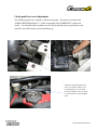
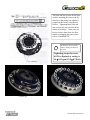
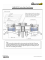
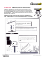
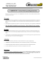
ACROSS USA INC
w w w. c a r b o n e t i c . n e t
TEL:310-635-3555
CARBONETIC Carbon Clutch operating instructions
Thank you very much for your purchase of the CARBONETIC carbon clutch. Please read these instructions before
operating the carbon clutch.
Warranty
•
ATS&ACROSS will not be responsible for any products which has been opened from the manufacture’s original containers or packaging. Our liability on any of our products will be released the instant they have been opened or
altered.
•
If the installation is impossible due to defective or incorrect parts, the proper parts will be supplied by CARBONETIC.
•
Once the clutch is installed or used in anyway, there will not be any warranty.
Warning
•
It is extremely important that the flywheel is properly installed since an improperly installed flywheel might cause a
serious accident. Use new bolts of proper length for flywheel assembly. Refer to the service manual for tightening
torque.
•
Clean the splines of input shaft and apply light transmission oil. Do not use heavy grease since grease tends to attract
the dust and might cause insufficient clutch disengagement.
Attention
•
The installation should be performed by an experienced mechanic at a properly equipped garage.
•
CARBONETIC clutch should be installed only to the car/transmission specified by each model number.
•
A long time half clutch operation will generate too much heat and will cause an engagement problem.
•
Use only CARBONETIC genuine parts for maintenance and adjustment of the clutch
Disclaimer
CARBONETIC products are manufactured for racing use. The user shall determine the suitability of our products
and assume all the risks and responsibility in connection with their use. Regarding the legality of the products, the
local laws vary from state to state. Please check with your local law enforcement.
Carbon Clutch all (08/08) 1
Cautions for Installation
•
Please make sure that you can move the clutch hub smoothly after you set it on the cleaned input shaft.
•
Please be careful with the handling of carbon discs. They are strong, but they could be broken if you put a big flexural force
on it. For example, please be careful on the right side of the center hub, installation procedure, and centering of the center
hub. Please do not shake the transmission very much when you set the input shaft.
•
Please minimize the use of grease on hubs and bearing sleeves because oils and fats would be the cause of slip because it’s
not easy to remove them from carbon. Please give a thin coat of transmission oil on the spline of the center hub.
•
Please do not use a big cylinder or a pivot which has a different length from the specified part because they could cause a
problem on releasing clutch, or they could make the clutch slippery.
•
Releasing point of clutch is different on each car. If it’s not easy to release the clutch even if you used the specified part and
minimizing the play of the pedal, please adjust the returning stopper to lengthen the pedal stroke. You could have to give
the master cylinder an overhaul.
•
Please use enough grease on those metal parts of push-type which were converted from pull-type and which metal parts are
touching each other. Please grease them periodically.
•
Please check if you can push and move the rod of release bearing by hand after adjustment. If you can not push it to move,
it means that the pedal has no play. If it has no play, the clutch oil expanded with heat can’t return to master cylinder cup. If
so, the oil pushes the rod of release cylinder out, and it would try to release the clutch, so the clutch would be slippery.
Please return the rod of the pedal about 120° if the pedal has no play.
•
It’s not easy to adjust the pedal on imported cars often. If so, you can’t adjust the releasing point of the pedal.
Operating a carbon clutch
Single, Twin, and Triple carbon clutch
•
A break in is important because special film is needed to be formed on the carbon discs. A large torque application and
slippage without this film will shorten the life of the carbon discs. The break in period is roughly 800 to 1000 miles.
•
Do not attempt to speed up break in and the formation of the film. The clutch engagement at high rpm and extensive use of
half clutch might risk warping of steel parts and ultimately will shorten the life of the clutch.
•
Warm up is strongly recommended for an abrupt start. Please refer to the “Warm up of disc” section below.
•
If a carbon clutch slips, the rev goes up instantly and you will notice immediately. If you experience slippage, ease up on
the accelerator and then start accelerating gradually. Keeping up the rev with slippage will only wear down the discs.
•
A short half clutch is recommended to avoid slippage and too much frictional wear.
•
A carbon disc wears down evenly at normal operation and ultimately becomes very thin. At that point, the disc might break
but it is not abnormal.
Warm up of disc
•
Perform warm up only when there is a risk of slippage (abrupt start or drag racing start). Too much warm up will cause
warping and excessive wear .
•
Drag racing is very tough to the clutch. In order to minimize the impact, please perform a warm up for the discs. Maintain
half clutch 3 seconds at around 2,000 rpm, and rest 20 to 30 seconds. Repeat the process 5 to 10 times. Do not engage half
clutch for more than 0.5 seconds and do not use higher rpm . It will produce too much heat and damage the clutch.
Carbon Clutch all (08/08) 2
CARBONETIC carbon clutch installation
•
Removal of the transmission. Please follow the service manual of the car.
•
Clearing of input shaft - Please clean the splines of the input shaft. Check any damage or deformation of the splines
and if there are, use a new parts.
•
For a clutch with casing. If you remove the casing from flywheel, use new bolts for re-assembly. The tightening
torque is 1.8±0.1 kg-m (13.0±0.7 lb-ft)
•
Flywheel assembly. Please pay the extra attention for the flywheel attachment since the inappropriate flywheel assembly might cause a very serious accident. Use new bolts for the attachment and use the right tightening torque specified
by the service manual of the car.
Flywheel tightening torque
Skyline GT-R, R32, R33, R34 tightening torque 14.5 -15.5 kg-m (104.9 - 112.1 lb-ft)
Silvia S13, S14, S15 tightening torque 8.5 - 9.5 kg-m (61.5 - 68.7 lb-ft)
EG6,EK4, EK9, DC2 tightening torque 10.5kg-m
For other cars — use the torque
CN9A, CP9A, & CT9A tightening torque 13.5kg-m
specified by the manufacturer’s
FC3S & FD3S tightening torque 6.2kg-m
service manual
Subaru WRX GC8,GDA,GDB tightening torque 7.6kg -m (55.0 lb-ft)
•
Use the stock clutch release parts. A big slave cylinder, different shape pivot and clutch fork might cause the insufficient disengagement due to the change of clutch stroke
•
Set the free travel (pedal play) between clutch pedal and master cylinder and the location of the pedal stopper to the
stock specification
•
If you have canceled the automatic adjustment of clutch to use another manufacturer’s clutch, please restore that function.
•
Remove the cover-ASSY, pressure plate, clutch plate A, clutch plate B, clutch hub from the flywheel. The casing is
fixed to the flywheel. Pressure plate and clutch hub have the top and bottom sides. It might be a good idea to
mark the direction at this point. Clutch has been assembled in the right direction when it is shipped out form the
factory.
•
Install the flywheel to the engine
•
Sequence of clutch assembly - clutch plate B, clutch hub, clutch plate A, clutch plate B (clutch plate A ===), Pressure
plate, and cover ASSY. Please refer to the diagram in the separate sheet.
•
Please see the cross section for the direction of the clutch hub. Clutch discs could be broken if you didn’t install correctly.
•
Pressure plate assembly. ( If the pressure plate is not fixed to the cover ) The hook of the pressure plate should face
the cover.
•
Cover ASSY (tentative tightening) assembly. Tighten the bolt in a diagonal sequence. Do not tighten fully until the
disk and bearing are aligned correctly.
•
Attach the cover ASSY to the casing lightly and use a centering tool to match the center of the hub to the center
of the crank shaft. (This process is very important to center the disk and hub on the flywheel)
•
With the disk aligned, tighten the attaching bolts.
Tightening torque for cover bolt 1.8±0.1 kg-m (13.0±0.7 lb-ft)
Carbon Clutch all (08/08) 3
•
Release parts assembly : By referring to the service manual , follow the proper procedure for your car. Pay enough
attention not to damage the splines of input shaft against the clutch plate. Unnecessary pressure will damage the discs.
Make sure you use a transmission jack.
•
Clutch fork (release fork) location: While the clutch bearing is in contact with clutch spring, make sure the clutch fork
is almost making a right angle with the mission axis. If the angle is out by more than 5 degrees , a change of spline
sleeve size might be necessary.
•
Air removal from slave cylinder: If the assembly involves loosening a bolt on the slave cylinder to relocate or realign the laying pipe, air removal (bleeding ) becomes necessary.
•
Clutch pedal adjustment: Adjust the rod between the pedal and the master cylinder so that the free travel is as
close as zero. It is important to make the free travel as small as possible but never set it negative - refer to another page (free travel adjustment)
•
Clutch pedal adjustment 2: Please operate the clutch in the normal driving condition, and check the release of
the clutch and the abnormality of the stepping power of the clutch. Please follow the maintenance manual for the
adjustment.
Brake in Drive around 800 to 1000 miles on the street. A drag race type start during the brake in period will significantly reduce the life of carbon clutch. Also please avoid a dyno test at full power before finishing the brake in period.
Avoid a long half clutch Long half clutch causes heat accumulation and hastens the warping of
pressure plate and floating plate resulting in a disengagement problem and difficulty of changing
gears. For an extended life of carbon clutch, try to engage the clutch with as little half clutch as
possible. ( less than 0.5 second) Carbon plates have a property of lubrication and can handle a very
short clutch engagement with little half clutch.
Carbon Clutch all (08/08) 4
Clutch pedal free travel adjustment
Incorrect adjustment on push-rod and piston behind the clutch pedal could lead to
Increased pedal pressure
Worn down
Slippage
Malfunction under heat
Refer to the diagram below and adjust the free travel of the pedal correctly
Important
Please pay attention to the following mechanism.
If the free travel (pedal play) is zero or negative
with the pushrod constantly pushing the piston,
the cup closes the return port of the oil which is
used to release the expanded clutch oil toward the
reserve tank. Then the clutch oil with nowhere to
go fills the cylinder and pressures the slave cylinder toward the disengagement , effectively creating constant half clutch situation.
Clutch pedal fulcrum
Push rod
Reserve tank
Return port
Lock nut
Cup
Pedal pin
Piston
Free travel
To adjust clutch pedal play, loosen the lock
nut and rotate the push rod. About 1/3 rotation of the push rod usually suffices
Cl
ut
ch
pe
da
l
See if you can
push the rod toward the arrow.
Slave cylinder
Release fork
Pivot
Bearing sleeve
Clutch bearing
Dish spring
Final inspection
After the assembly, refilling the clutch oil, and adjustment of free travel,
check to see if you can push the rod toward “P”. If you can push it, free
travel exists. If you cannot, that means the clutch oil is unable to go
back into the reserve tank.. The free travel is negative. You must readjust the pedal play.
Clutch
Carbon Clutch
Carbonall
Clutch
(08/08) 5
Clutch pedal free travel adjustment
The following pictures are examples of the previous page. The pictures are taken from
ATS&ACROSS Mitsubishi Evo 7 which is equipped with CARBONETIC carbon twin
clutch. You should be able to push the reverse rod inward and when you push the reverse
rod, the level of fluid in the reservoir should go up.
Push the rod to the direction of the
arrow, the fluid level in the reservoir should go up. If you cannot
press the rod, the free travel is negative and you have to make an adjustment.
Carbon Clutch all (08/08) 6
The bolts and nuts (except for the ones
used for attaching the cover to the flywheel or to the casing) are tightened
properly at the factory using threadlockers. Tightening those bolts and
nuts excessively may cause the deformation or breakage. In the case you
have to remove those bolts for disassembly or changing the parts, please
refer to CARBONETIC.
The bolt-nuts for cover to flywheel or casing are shown in
the circle
Tightening torque for cover
ASSY to flywheel or casing is
1.8±0.1 kg-m (13.0±0.7 lb-ft)
Compact type
Casing type
Carbon Clutch all (08/08) 7
CARBONETIC Carbon Triple Clutch Diagram
Clutch Cover ASSY
Coned spring
Coned spring
Ring (2)
Bolt set w/ nuts (18)
Height A (distance from the wire to the top)
should be bigger than the height B (distance
from the wire to the bottom). One wire is
installed on the hub at the factory
Plate (1)
Clutch cover
Pressure plate (1)
Bolt set w/washer (20)
Casing
Flywheel
Clutch plate A
Clutch plate B
Bolt set (20)
Clutch hub
Note:
There are top side and bottom side for the pressure plate and clutch hub. Please pay
attention to install them in the correct direction. Clutch plate A & B for new one do not
have the sides. ( Once you use a clutch, it is important to place back all the plates with
same order / side during the reassembly. )
Carbon Clutch all (08/08) 8
ATTENTION: Important points for clutch assembly
CARBONETIC carbon disc is very strong and does not break under the normal use. However,
under unusual circumstance it might break like when the significant force is applied perpendicular
to the disc. Even though the disc might not break, the force might cause a crack and result in disc
failure during the driving. In order to avoid the possible damage to the carbon disc, please pay the
attention to the points described below.
CARBONETIC carbon disc does not break unless excessive force is applied during the assembly. ATS&ACROSS will not exchange the carbon disk broken due to a wrong handling.
Correct
side ??
If a disc has up / reverse side, install it in
the right direction
Use a proper alignment tool to center the discs on the flywheel
Use a transmission jack in order to avoid unnecessary
force on the disc during the input shaft assembly.
Unnecessary force might break the carbon
disc
Do not shake the
transmission.
Might cause cracks
on the disc.
Do
t
no
dr
op
e
th
cl
ch
ut
an
d
di
s
sc
Carbon Clutch all (08/08) 9
Caution for clutch assembly
Inspect the input shaft splines for possible warp, twist, and rust before attaching the clutch to the mission. If there are any abnormalities, repair it or use
new parts.
*** Checking abnormalities like deformation, twist, and warp of splines ***
Insert the clutch hub onto the input shaft splines and see if it slides smoothly.
Input shaft
Warning
The carbon discs will break if an input shaft with abnormalities
is forcefully installed on the clutch.
Carbon Clutch all (08/08) 10
Attention: When drag racing, please pay attention to:
Burnouts & dry hop without warm up will warp the pressure plate and floating plates !!
Burnouts - A method, at the start, to increase the tire grip to the maximum by intentionally inducing wheelspin and by
generating heat in the tires.
Dry hop - A short practice launch. By bringing an engine up to a launch rpm, then launching to examine the tire grip
and engine response. Depending on how the car reacts, you will adjust your launch rpm.
Before burnouts / dry hop, a warm up of the clutch is essential
1) With emergency brake applied, maintain the half clutch at 2,000 rpm for 3 sec
2) Disengage the clutch for 20 to 30 sec
3) Repeat the above mentioned process 5 to 10 times.
Do not - use higher rpm and more than 0.5 second duration for half clutch. It accelerates the wear down and could cause warping of the plates.
CARBONETIC carbon disc does not wear down as much and as fast as the metal
disc. However, ATS&ACROSS will not be responsible for the possible negative impact on the durability of discs due to repeating this warm up process. Keep the duration of the half clutch as short as possible for the actual drag start.
Powershifting might cause the clutch to slip even though the horsepower is well within the rated range specified by ATS&ACROSS
Carbon Clutch all (08/08) 11
Warning
Page 5, 9, & 11 are especially important. Please make sure you and your mechanic read those pages and follow.
Page 5 - clutch pedal free travel adjustment. If the free travel is not adjusted correctly (as described in the page with effective constant half clutch
situation, the carbon discs wear out very quickly and cause early malfunction.
Page 9— close to 100% of early failure/break of the carbon discs are caused
by cracks made during the installment. Use a transmission jack and do not
shake the transmission onto the engine at the installment.
Page 11 - Even though the carbon discs last much longer than metal under
the same operation, they produces more heat. The heat accumulation from an
extended half clutch (slipping clutch) at high RPM will warp the pressure
plate causing early failure of the clutch. Our carbon clutch due to its surface
lubricated characteristics (the surface of the carbon disc acts like as if oil is
applied on it) can handle a rapid engagement.
Use half clutch as short as possible, preferably less than
0.5 second. (At the drag racing)
Carbon Clutch all (08/08) 12