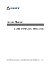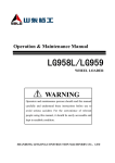
1
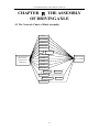
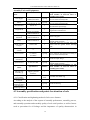
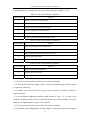
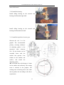
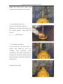
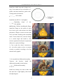
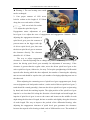
Service Manual
3T WHEEL LOADER DRIVING AXLE
Applicable Scope:LG938、LG936、LG933
Series Wheel Loader Driving Axle
SHANDONG LINGONG CONSTRUCTION
MACHINERY CO.,LTD
3T LOADER DRIVING AXLE SERVICE MANUAL
Driving Axle Service Manual
2008-9
Version 1
2008-9
Printed 1
SHANDONG LINGONG CONSTRUCTION
MACHINERY CO.,LTD
Address: Lingong Industry Park, Linyi Economic Development
Zone, Shandong, china
Tel:+86 539 8785597
Fax: +86 539 8785618
Email: [email protected]
Website:
http://www.sdlg.cn
II
3T LOADER DRIVING AXLE SERVICE MANUAL
Service Manual
Concise Guide
All reasonable steps have been taken to ensure that this publication is correct
and complete, but should any user be in doubt about any detail, clarification
may be sought from Shandong Lingong construction machinery Co. Ltd. or
their accredited representative. The information in this document is subject to
change without notice and should not be construed as commitment by
Shandong Lingong construction machinery Co. Ltd. Shandong Lingong
construction machinery Co. Ltd accepts no responsibility for any errors that
may appear in this document.
Shandong Lingong construction machinery Co. Ltd, P. R. China
All rights reserved. The contents of this publication may not be reproduced in
any form, or communicated to a third part without prior written permission of
Shandong Lingong construction machinery Co. Ltd.
III
3T LOADER DRIVING AXLE SERVICE MANUAL
PREFRACE
This service manual, which shows the structure, principle and the maintenance technology of
the driving axle, will help the maintenance workers understand the disassemble and
assemble method of driving axle more deeply and bring the maintenance workers solid
technology basis of locating faults and maintaining correctly.
Main content of the Service Manual:
1. Structure and working principle of the driving axle
This chapter shows the structures and functions of each kind of part, which establish the
basis of assembling and disassembling driving axle. Furthermore, it also could be used as the
reference of locating faults.
2. Disassembling of the driving axle
The steps how to disassembling the parts correctly and the points for attention in
disassembling driving axle are shown in this chapter.
3. Assembling of the driving axle
The steps how to assembling the parts correctly and the points for attention in assembling
driving axle are shown in this chapter.
4. Standard of criterion of the driving axle for repairing and replacement
of parts
The identification methods and standards of criterion of vulnerable parts are formulated in
this chapter.
Especially declaration:
This service manual narrates the LG938 Driving Axle as an example. Other series
Driving Axle are similar with it except some small differences in connection types and
structures. They will not be narrated again here and could be executed as the method
described in this manual.
ATTENTION
Forgiving without further notice about the specification’s changing of the parts in this
manual, which are caused by the complete appliance development. The latest
information could be get from Shandong Lingong Construction Machinery CD., LTD.
IV
3T LOADER DRIVING AXLE SERVICE MANUAL
Table of Contents
CHAPTER Ⅰ EXORDIUM .......................................................................................................................1
1.1 Safety Considerations......................................................................................................................1
1.2 Oil and Coating Materials ...............................................................................................................3
1.3 Marker .............................................................................................................................................4
1.4 Hoisting Explanation.......................................................................................................................4
1.5 Table of Common Screw Tighten Torque........................................................................................6
CHAPTER Ⅱ CONSTRUCTION AND WORKING PRINCIPLE OF THE DRIVING AXLE ...............7
2.1 Outside Graphic...............................................................................................................................7
2.2 General Graphic ..............................................................................................................................8
2.3 The Internal Construction of Driving Axle .....................................................................................9
2.4 Working Principle of the Driving Axle..........................................................................................10
CHAPTER Ⅲ DISASSEMBLY OF DRIVING AXLE ............................................................................13
3.1 Transmission Net Graphic (corresponding to disassembly of driving axle)..................................13
3.2 Disassembly of transmission .........................................................................................................15
3.3 Disassembling of assemblies.........................................................................................................19
CHAPTER Ⅳ THE ASSEMBLY OF DRIVING AXLE ..........................................................................29
4.1 The Network Chart of Final Assembly..........................................................................................29
4.2 Assembly specification and points for attention of axle................................................................30
4.3 Assemble the driving axle .............................................................................................................34
4.4 Partial assemble the assembly .......................................................................................................40
CHAPTER V JUDGEMENT STANDARDS OF MAINTENANCE AND CHANGING PARTS IN
SERVICE MANUL FOR DRIVING AXLE ...............................................................................................54
V
3T LOADER DRIVING AXLE SERVICE MANUAL
CHAPTER Ⅰ EXORDIUM
1.1 Safety Considerations
Important Safety Considerations
It’s very important to operate the loader safely in the process of maintenance and
repairing. The related technologies about how to assemble and disassemble the
driving axle correctly are described in this manual.
The safety considerations, marked with
as the security label, should be pay
more attention when operate it for avoiding hurting workers. When coming across this
kind of marker, workers should operate carefully. Workers should keep themselves
safe first and take some necessary measures when the potential dangers coming.
Security Attentions
In the process of assembling and disassembling, unsafe factors and parts wear, life
losing, properties failure would be caused by the incorrect operation method. Please
read the contents carefully when the transmission’s parts would be assembled or
disassembled.
1. The parameters, graphs and contents in this manual are suitable to the standard
configuration products. Please consult our company and search data about the
information of deformed products.
2. In repair shop, the region for assembling or disassembling and placing
disassembled parts should be marked obviously. Mark sure the tools and parts are
placed in the right region. The clean of operation region must be kept and make sure
no oil or pollution in the operation region. Fire extinguishing equipments are
necessary and smoking is forbidden in the region except the smoking room.
3. When welding operation is needed, it should be done by expert workers who were
trained by professional welding training. Welding gloves, baffles, goggles, hats and
other work clothes suitable for welding are essential during welding operation.
4. Before the driving axle assembly been disassembled, the appearance of which must
been cleared up to avoid the parts been polluted in the disassembling progress.
5. Work clothes not coincide with requirements are forbidden. In the progress of
1
3T LOADER DRIVING AXLE SERVICE MANUAL
operation, safety shoes and safety helmets must been worn and the buttons must been
attached. Goggles should be worn when workers knock the parts with copper rod.
6. The disassembled parts could be cleaned by petrol, gasoline and water-base oil
cleaner.
7. Check the spreaders whether were broken before operate the cranes and other
hoisting equipments. The quantity of the spreader must be big enough. For avoiding
collisions between parts, spreaders should been operated slowly and located in the
correct region. Make sure no one work under the part lifted.
8. When two or more workers will work together, the operation procedure abided by
all of who should be made before work for avoiding the accidence caused by out of
steps.
9. All tools should be been familiar with and kept carefully.
10. When align two holes, the workers make sure their hands and figures are not in
the holes. Pay attention to whether the hands would be extruded when assemble parts
with hands directly.
11. The disassembled parts must be checked. The parts which have poor properties
should be changed, and the standard of criterion could be found in chapter
5--Standard of criterion for repairing and replacing the parts of the driving axle.
12. There should be no interference after assembling each part.
13. Protection measures must be operated, when the oil seal and seal ring across key
seats, screw holes and steps, to protect the oil seal and seal ring.
14. To protect screw fasteners, all the tools must be suitable to the screw fasteners
when assemble the parts.
15. The gas trigger is forbidden when tighten the screws. Tighten them with hands
first, and then tighten them with some specification wrest wrenches to reach the
torque demanded.
16. When release the oil in the driving axle, releasing-screw should be loosen off
slowly to avoid the oil blowout. The oil drained out should be get with special vessel
to prevent the environment pollution.
2
3T LOADER DRIVING AXLE SERVICE MANUAL
1.2 Oil and Coating Materials
The similar foreign oil brands (Be classified by the U.A. API, GL-5 )
Kinematic
Viscosity
(100℃)
Domestic oil brands
Heavyduty motor
Auto-oil
85w-90 GL-5
GB13895-1992
mm2/s
MOBIL
13.5~24.0
Mobilube 1 SHC
synthetic oil
MOBIL Auto-gear oil
HD80W-90
(-20~40℃)
MOBIL Auto-gear oil
HD85W-140
(-10~50℃)
ESSO
SHELL
Spirax EP
Multi
Purpose
Gear oil GX
Heavyduty
85W-90
HD90
Thuban EP
HD80W-90
The similar foreign oil brands
Domestic oil
brands
MOBIL
CALTEX
2# or 3# lithium
MOBIL
Marfak
grease
grease
multi
GB7324-1994
XHP222
Purpose
Name
CASTROL
ESSO
BP
SHELL
Ronex
LM grease
MP;
Energrease
Beacon
L
Retinax A;Alvania
EP 2
Code
1545
oxygen-weary
pipe-thread sealant
Sealant
CALTEX
Application scope and function
type
1262 pipe-thread fixed sealant
It’s suitable to be used to seal the pipe-thread of
Hydraulic system and pneumatic system or be used on
the surface with little oil.
It’s used to fix and seal the M10~M20 screws and the
ones be endured intense vibration and impact.
1596 silicone rubber surface It’s used to seal the joint face on the parts of reductor 、
water pump、valve and gas engine。
sealant
Grease
Cleaning
agent
2# or 3# lithium grease GB
7324-1994
1755 cleaning agent
It’s suitable to be used to lubricate the fiction position,
rolling bearing and sliding bearing of any kinds of
engineering machinery between -20~120℃.
It’s used to clean the surface of metals and enhance the
adhesion strength between repair agent, pope-thread
fixed sealant and substrate.
3
3T LOADER DRIVING AXLE SERVICE MANUAL
1.3 Marker
To make this manual to be more useful, these markers following are used to mark
the important safety and quality.
Marker
Item
Remark
Safety
Take care in the operation.
Attention
Pay attention to the technical requirements and make sure the
operations reach the requirements in operation.
Heavy
Choose the appropriate spreader by the parts and their heavy. And
choose the right assembly way by the spreader’s conditions in
operation.
Tighten
torque
Pay more attention to the parts’ tighten torque in assembly
operation.
Coating
The location where need to be coated with adhesive and grease.
Oil and
water
Inject required volume of lubricating oil, water or fuel oil.
Outpour
Outpour required volume of oil or water or.
1.4 Hoisting Explanation
1. When it is not easy to assemble the parts from driving axle assembly,check the
following items:
z
Check that whether all of tightening bolts of the part have been assembled.
z
Check whether the parts being disassembled are hindered by some other
parts.
2. Wire Rope
1) Wire rope should be in the middle of the hook. If be in one end of the hook, the
wire rope may drop from the hook and that may cause serious accident. The biggest
4
3T LOADER DRIVING AXLE SERVICE MANUAL
strength is in the middle of the hook. As shown in graphic 1-1.
2) One single wire rope is forbidden. Make sure that two or more ropes are used in
hoisting the heavy.
Gr.1-1
Hoisting with one wire rope may cause the heavy rotates, and then the wire
rope looses or the heavy slides from the fixed location which will cause serious
accidence.
3) The hoisting angle between wire rope and hook should not be oversize when
hoist the extremely heavy loading.
When the hook hoists heavy loading with two or more ropes, the bigger of angle
between wire rope and hook is, the heavier of each rope loads. The graphic 1-2
shows the changes of allowed loading (kg) in different angles when hoisting with
two ropes (The limited vertical hoist loading of each rope is 1000 kg). It can hoist
2000kg when two ropes in the vertical location. But when the angle reaches to 120°,
the ropes can only hoist 1000kg. Another hand, the force of the ropes would be
4000kg when the angle reaches 150°, although the loading is only 2000kg.
Gr.1-2
5
3T LOADER DRIVING AXLE SERVICE MANUAL
1.5 Table of Common Screw Tighten Torque
Screw
Strength
Grades
4.6
5.6
6.8
8.8
10.9
12.9
Screw
Strength
Grades
4.6
5.6
6.8
8.8
10.9
12.9
Screw
Strength
Grades
4.6
5.6
6.8
8.8
Yield
Strength
N/mm2
240
300
480
640
900
1080
Yield
Strength
N/mm2
240
300
480
640
900
1080
Yield
Strength
N/mm2
240
300
480
640
10.9
900
12.9
1080
6
4~5
5~7
7~9
9~12
13~16
16~21
16
90~110
110~140
145~193
193~257
280~330
326~434
27
450~530
550~700
714~952
952~1269
1400~
1650
1606~
2142
Screw Nominal Diameter mm
8
10
12
Tighten Torque N·m
10~12
12~15
17~23
22~30
30~36
38~51
20~25
25~32
33~45
45~59
65~78
75~100
36~45
45~55
58~78
78~104
110~130
131~175
Screw Nominal Diameter mm
18
20
22
Tighten Torque N·m
120~150
150~190
199~264
264~354
380~450
448~597
170~210
210~270
282~376
376~502
540~650
635~847
230~290
290~350
384~512
521~683
740~880
864~1152
Screw Nominal Diameter mm
30
33
36
Tighten Torque N·m
14
55~70
70~90
93~124
124~165
180~210
209~278
24
300~377
370~450
488~650
651~868
940~1120
1098~1464
39
540~680
680~850
969~1293
1293~1723
670~880
825~1100
1319~1759
1759~2345
900~1100
1120~1400
1694~2259
2259~3012
928~1237
1160~1546
1559~2079
2923~3898
1700~2000
2473~3298
2800~3350
4111~5481
2181~2908
2968~3958
3812~5082
4933~6577
Remark: In the process of assembling, the tightening torque of the connection
bolts could be referred to the above table. When the tightening torques in chapter 4
are not the same as in this table, just follow the torque in chapter 4.
6
3T LOADER DRIVING AXLE SERVICE MANUAL
CHAPTER Ⅱ CONSTRUCTION
AND WORKING PRINCIPLE OF
THE DRIVING AXLE
2.1 Outside Graphic
1. End cover 2. Wheel-side reducer assembly 3. Brake clip assembly 4.Axle shell
5. Main transmission 6. Input flange 7. Oil-draining plug 8. Wheel hub assembly
7
3T LOADER DRIVING AXLE SERVICE MANUAL
2.2 General Graphic
Base parameters of driving axle:
Main
Transmission
Wheel-side
Reducer
Oil for Axle
Type
Spiral Bevel Gear First-order Deceleration
Reduction Radio
6.167
Type
First-order Planetary Deceleration
Reduction Radio
3.12
SAE85W-90 GL-5
Gear Oil
13 L
8
3T LOADER DRIVING AXLE SERVICE MANUAL
2.3 The Internal Construction of Driving Axle
Driving axle assembly is one of the most important parts in transmission system. The
main function of driving axle are turning the rotation speed slower and increasing
torque from transmission. The axle brings differential speed function to the two-side
wheels. Bearing load and transmitting power are also the functions of driving axle.
Driving axle of loader is made up of axle shell, main transmission driver (including
differential mechanism), half-axis, wheel-side reducer and brake clip assemblies. The
parts with the function of reducing or differencing speed are main transmission driver
and wheel-side reducer. Main transmission driver is made up of input flange, oil seal
cover, bearing sleeve, driving spiral bevel gear, driven spiral bevel gear, bracket,
differential mechanism (planetary wheels, cross shaft, half-axis gear, left shell of
differential mechanism, right shell of differential mechanism, gasket), bearings,
adjusting shim, stop-pushing bolts and framework oil seal. Wheel-side reducer is
made up of internal gear ring, planetary wheel carrier, planetary wheel, solar wheel
and shims. The main internal structures are shown in Graphic 2-1.
The power transmission between main transmission driver and wheel-side reducer is
realized by half axle. The splines on the two end of half axle mesh with the half axle
gears in differential mechanism and the solar gear in wheel-side reducer, and it
connect the power between main transmission driver and wheel-side reducer.
Graphic 2-1
9
3T LOADER DRIVING AXLE SERVICE MANUAL
2.4 Working Principle of the Driving Axle
Driving axle assembly function of increasing torque, reducing speed and differencing
speed are realized by differential mechanism and wheel-side reducer.
Working principle will be introduced as followed:
1. Working principle of differential mechanism—Motion Characteristic:
The symmetrical bevel gear differential mechanism used in driving axle assembly is a
kind of planetary gear mechanism. Planetary is composed with differential gear shell
and cross shaft, both of which are connected together. At the same time, differential
gear shell is driving part because it connects with driven spiral bevel gear. We assume
that the angle speeds of differential gear shell and two-side half axle gears are
ω0(revolution per minute is n0), ω1 and ω2(revolutions per minute are n1 and n2), then
the following equations will be right:
2ω0 = ω1 + ω2
2n0 = n1 + n2
These equations are the motion characteristic equations of symmetrical bevel gear
differential mechanism with two same diameter half axle gears. They show that the
sum speed of left and right half axle gears is same as two times of the speed of
differential gear shell but isn’t relation with the speed of planetary gears. So, when the
loader turns or drives on other condition roads, the planetary gears can rotate on their
own speed to make the wheels on two sides rotate in different speed but not slide. The
up equations show that:
①When one side half axle speed is zero, the other speed is two times of the
differential gear shell.
②In the condition that the speed of differential-gear shell is zero, when one side half
axle is rotated by external power, the other side will reverse rotate in the same speed.
2. Working principle of differential mechanism—Torque Distribution:
Assume: The torque from main reducer to symmetrical bevel gear differential
mechanism is M0; inside and outside of half axle torques, which are distributed by the
differential gear are M1 and M2; internal friction torque of differential gear is Mr:
M2+M1=M0
M2-M1=Mr
The followed conclusions will be get from the equations:
①When the torques from left and right half axle are different, the difference value of
them works on the planetary gears and overcome the internal friction torque of
10
3T LOADER DRIVING AXLE SERVICE MANUAL
differential gear to drive the planetary gears. This makes the differential action.
②When the speeds of left and right half axle are different, torques on them are
different too. Torque on the slower axle is bigger and that on the faster axle is smaller.
③The sum torque on two half axles is the same as the one on differential gear.
Because the friction torque of the popular symmetrical bevel gear differential
mechanism is very small, it could be thought the torque is distributed equally whether
the speeds of left and right wheel are same. This is the transmission
characteristic—the same torque, but the different speed of common differential
mechanism. This characteristic is suitable for loader when works and drives on the
general condition. But in the wicked condition, the passing capacity will be affected
seriously.
3. Working principle of the wheel-side reducer
Wheel-side reducer is the last increasing torque and reducing speed mechanism.
It is a kind of planetary transmission mechanism. It is made up of solar gear, fixed
gear ring, driven planetary carrier and planetary gears. Working principle is shown as
Graphic 2-30. (This graphic is not complete the same as the actual structure and here
is just the principle introduction)
Graphic 2-30 Working principle of wheel-side reducer
1. Internal gear ring 2. Planetary carrier 3. Half axle 4.Planetary gears
5. Wheel hub 6. Solar gear
Solar gear is connected with half axle by spline. Internal gear ring is fixed on the
wheel-side supporting axis which on two ends of driving axle shell. Planetary gears
mesh with solar gear and internal gear ring. The planetary gears are installed on the
11
3T LOADER DRIVING AXLE SERVICE MANUAL
planetary gear carrier by steel balls and planetary gear axis. Planetary gear carriers are
fixed with hub as one system by the bolts. So, planetary gear carriers and hub rotate
together.
For improving the meshing condition between solar gear and planetary gears and
contributing the meshing load equally, half axle is in condition of floating state but not
fixed.
4. Transmission principle of driving axle
As shown in the graphic 2-1, the main internal structure of driving axle shown: The
left and right shells of the differential mechanism are connected by bolts. The driven
spiral bevel gear of the main transmission is fixed on the flange edge of the
differential right shell. Journals of the cross axis inlay in the holes which are formed
by the relevant groove which on the joint face between left and right shells. One
planetary gear incases on the journal of cross axis without fixed. Both of the gear and
cross axis mesh with the two straight tooth conical half axle gears. The journals of the
two half axle gears install on the left and right base holes on the differential shell and
connect with half axle by splines.
Half axle is solid shaft between differential mechanism and wheel side reducer. Its
inside end connects with half axle fear by spline and its outside end connects with
shield ring and solar gear of wheel side reducer by splines. The left and right half
axles of loader are full floating structure. Two ends of half axle bear torque mainly
because of the kind of structure. For avoiding half axle motions along axis, the end
which connects with wheel side reducer solar gear is limited by steel balls. The torque
and speed are transmitted to half axle by differential mechanism. And then, they will
be transmitted to wheel side reducer by half axle.
Solar gear connects with half axle by spline. Internal gear ring is fixed on the two
ends wheel side bearing shafts of driving axle shell by splines. They are fixed. The
planetary gears, which mesh with solar gear and internal gear ring, are installed on the
planetary carrier by steel balls and planetary gear axis. Planetary carrier and hub are
connected by hub bolts. So, planetary carrier and hub will rotate together.
Transmission way will be get from the above structure:
Transmission (power) → Transmission shaft → Input flange → Driving spiral bevel
gear → Driven spiral bevel gear → Left and right shells of differential mechanism →
Half axle gear → Half axle → Solar gear → Planetary gears → Planetary carrier →
Hub assembly → Driving wheels.
12
3T LOADER DRIVING AXLE SERVICE MANUAL
CHAPTER Ⅲ DISASSEMBLY OF
DRIVING AXLE
3.1 Transmission Net Graphic (corresponding to disassembly of
driving axle)
13
3T LOADER DRIVING AXLE SERVICE MANUAL
Tools and Equipments of Disassembling
Name of
general tools
Specification
Number
Application position (corresponding to net
graphic number or assembly name)
Gas trigger
LB10, LB16A, LB20A,
M1-20P
1group
Choose different specification by size of
screws
Sleeve
13, 16, 17, 18, 21, 24,
27, 30, 34, 41, 50
1group
Choose different specification by size of
screws
1
In the process of hanging, flick the firm parts
by it; Flick bearings when disassembly them
6
1
12
Specification
Number
Application position (corresponding to net
graphic number or assembly name)
Prepare assembly
platform when no one
with transmission
1
Copper bar
Hexagonal
wrench
Name of
special tools
Assembly
carrier of
driving axle
Shield ring
pliers for axis
(hole)
Round nuts
special tools
Screw pusher
Each with 1
Disassemble the shield ring
1
12
Replace it by common
bolts according to size
of screw holes
3、10、17
Explanation about Disassembling—Part
1. Do not reuse the disassembled parts, and replace them with the new;
2. Magnitude of reference of part bearings are relatively large because they were
assembled by heated and pressed assembling in factory, which will bring injury to
bearings. The bearings, whose faces are damaged in disassembling, could be reused in
condition of being repaired and achieving the standard. Otherwise, scrap the bearings.
3. When the copper bar is used, knock the parts as lightly as possible to avoid the
debris splashing into the assembly. Or you can choose rubber hammer, plastic hammer
or other press-assembly method.
Preparative work
1. Clean the soil and fouling on the duplex-transmission assembly completely.
2.
Prepare firmly driving axle assembling carrier.
14
3T LOADER DRIVING AXLE SERVICE MANUAL
3.2 Disassembly of transmission
1. Place the driving axle assembly on carrier
horizontally. Make the main transmission
assembly up.
Driving Axle Assembly
2. Disassemble the brake clip assembly
Use relevant tools (Such as sleeve and open
end wrench; the following conditions are
similar and won’t be explain again)
Loose off the bolts connect the brake clip
assembly and carrier. Disassemble the brake
clip assembly.
3. Disassemble end cover
Loose off bolts connect the planetary carrier
and cover by relevant tools. Push end cover
away from wheel side assembly with M10
pusher screw. Disassemble end cover.
4. Disassemble the limit-block.
Take off the limit-block and steel balls together with
hands.
Relevant tools could be used when the parts are
a little tight.
15
3T LOADER DRIVING AXLE SERVICE MANUAL
5. Disassemble the steel balls
Remove the locating point of steel balls with
tools and make them out.
6. Disassemble shield ring
Take out the shield ring from half axle ring
groove by axis shield ting clip.
Before disassemble shield ring, draw the
half axle out certain distance along the shell
first.
Make sure that the pliers be clamped
firmly to avoid it bouncing off to bring
potential safety hazard.
7. Disassemble the solar gear
Take off the solar gear from half axle slightly
by hands.
8. Disassemble half axle.
Draw out the half axle from axle shell slightly
by hands.
16
3T LOADER DRIVING AXLE SERVICE MANUAL
9. Plug screw
Loosen the plugs on the wheel side and the
axle shell. Unscrew it with hands carefully
and avoid the oil splashing.
Prepare a clean vessel under it to get oil.
10. Wheel side reducer
Loose off the hub bolts with relevant tools
first. And then, Push planetary carrier away
from
hub
with
M16
pusher
screw.
Disassemble planetary wheel carrier assembly.
When pushing planetary carrier with
pusher screw, the carrier must be pushed
carefully for avoiding too fast to fall it down
bringing potential safety hazard.
11. O-shape ting
Take off the O-shape ring from planetary
wheel carrier by hands.
12. Disassemble round screws.
Loosen off the looseness-proof bolts of the
circle nut. And then, disassemble the circle nut
with hands.
17
3T LOADER DRIVING AXLE SERVICE MANUAL
13. Disassemble internal gear ring
Take off the internal gear ring.
14. Disassemble rolling bearing
Rock the hub assembly slowly. Separate the
internal ring of 32221 away from wheel side
supporting and get off the internal ring.
15. Disassemble hub assembly
Take down the hub assembly from wheel side
support axis.
Hub assembly
In the process of hanging-disassembling,
keep the axis of hub assembly and the axis of
wheel side support axis being in the same line
approximately to avoid hurting the oil sealing
face and the internal parts.
16. Disassemble the sleeve gasket
Take down the sleeve gasket.
Remark: Disassemble all the parts on the
other side of driving axle in the same way.
18
3T LOADER DRIVING AXLE SERVICE MANUAL
17. Disassemble main transmission assembly
Loose off the bolts connecting the main
transmission and axle shell assembly. Hang
transmission assembly off..
Main transmission assembly
In
the
process
of
hanging
main
transmission assembly, the hanging tool
should be kept above the transmission
assembly to avoid hurting internal parts in the
process.
3.3 Disassembling of assemblies
3.3.1
Disassemble
planetary
wheel
carrier
assembly
1. Put
planetary
carrier
on
working
plate
horizontally.
2. Knock the planetary wheel carrier out with
the copper bar
3. Take out the steel balls.
19
3T LOADER DRIVING AXLE SERVICE MANUAL
4. Take down the planetary gears and gasket.
5.
Disassemble the shield ring first. And
then take down the noodle roller on the
internal wall of planetary gears.
3.3.2 Disassemble the hub assembly
1.
Put hub assembly on working plate
horizontally.
2.
Loose off the bolts connect brake plate
and hub with relevant tool.
20
3T LOADER DRIVING AXLE SERVICE MANUAL
3. Take down the brake plate
4.
Loose off the bolts connect the oil seal
end cover and the hub. Take down oil seal end
cover.
5. Take down gasket
6. Take down frame oil seal
21
3T LOADER DRIVING AXLE SERVICE MANUAL
7. Get the bearing out
3.3.3
Disassemble
main
transmission
assembly
1.
Fixed the main transmission (face the
input flange up) on the carrier horizontally.
2.
Loosen the locking nuts off with relevant
tool. Take down input flange, gasket, O-sharp
ring and the shield ring.
3.
Loose off the bolts connect seal cover and
bearing sleeve and take the seal cover down.
22
3T LOADER DRIVING AXLE SERVICE MANUAL
4.
Take down frame oil seal from seal cover
with specific tool.
5. Take down the gasket by hands.
6. Turn the main transmission 180°
7. Disassemble locking iron wire
Some machine type structure may be not
the same as this graphic. Adjust the
operation content in actual work in the
disassembling process.
23
3T LOADER DRIVING AXLE SERVICE MANUAL
8.
Loose off the bolts fix locking plate and
take down locking plate.
9.
Mark the part for reinstalling it to the
original position.
10.
Loose off the bolts connect the bearing
base and dismount the bearing base.
11. Dismount adjusting nuts with hands.
24
3T LOADER DRIVING AXLE SERVICE MANUAL
12. Knock
down
the
locking
plate
of
stop-pushing bolt and dismount the nuts. Take
down
locking
plate
and
disassemble
stop-pushing bolt.
13. Hang out the differential mechanism
assembly
Differential mechanism assembly
Keep balance in the hanging progress to
avoid bringing potential safety hazard.
14. Separate
driving
spiral
bevel
gear
assembly and bracket with copper bar.
Don’t knock the spiral bevel gear
assembly too abruptly to avoid it falling down
to scratch parts or bring potential safety
hazard.
3.3.4 Disassemble the differential mechanism
assembly
1.
Put differential mechanism assembly on
the working plate vertically and firmly.
25
3T LOADER DRIVING AXLE SERVICE MANUAL
2.
Loose off the nuts connect the driven
spiral bevel gear and the right shell of
differential mechanism and disassemble the
driven spiral bevel gear.
Before take down driven spiral bevel
gear, check or mark the assembly label first to
reinstall the part to initial position.
3.
Dismount the bearings on the left and
right shells of differential mechanism.
4.
Loose off the nuts connect left and right
shells and separate the left and right shells of
differential mechanism.
Before separate left and right shells,
check or mark the assembly label first to
reinstall the part to initial position
5.
Take down half axle gear gasket and half
axle gear.
26
3T LOADER DRIVING AXLE SERVICE MANUAL
6. Take down the cross and differential
gear
together,
then
take
down
the
differential gear gasket and differential
gear from the cross.
7. Take down the axle shaft gear gasket
and axle shaft gear.
3.3.5 Disassemble the spiral bevel driving
gear assembly
1. Put the spiral bevel driving gear
assembly on the proper worktable, and put
up the flange of bearing sleeve, and then
exert pressure on the thread end of spiral
bevel driving gear.
During exerting pressure, the pressure
should not be so high to prevent
destroying the flange. If so, the spiral
bevel driving gear will be pulled off by the
bearing sleeve.
2. Remove the bearing.
27
3T LOADER DRIVING AXLE SERVICE MANUAL
3. Remove the bearing sleeve.
4. Remove the adjusted gasket.
5. Remove the sleeve.
28
3T LOADER DRIVING AXLE SERVICE MANUAL
CHAPTER Ⅳ THE ASSEMBLY
OF DRIVING AXLE
4.1 The Network Chart of Final Assembly
Sleeve
2
Rim Assembly 3
Bearing
Internal Gear
1
Fix the driving axle
shell which is
cleaned on the
assembly jig
4
5
6
Round Nut
7
O-ring Planet Gear 8
9
Plug
10
Refuel
11
Brake
12
Refuel
13
Main Drive
14
15
Sun-gear
Shield Ring
16
Half Axle
17
18
Locating Block
Steel Ball
End Cover
19
29
LG938 driving
axle assembly
3T LOADER DRIVING AXLE SERVICE MANUAL
Assembly Tools and Equipments
General
name
tool
Gas trigger
Sleeve
Dial Indicator
Specification
LB10, LB16A,
LB20A, M1-20P
13, 16, 17, 18, 21,
24, 27,30, 34, 41, 50
0.01/0~10
Copper Rod
Number
1 group
1 group
1
1
Using Position(corresponding to the
serial number of network chart or
assembly parts name)
Select different specification according to
the size of the assembly bolts
Select different specification according to
the size of the assembly bolts
Partial assemble the main driver assembly
and install the input flange
Lightly beat the parts with assembly
magnitude of interference
Please use another
method without it
Please use another
method without it
Please use another
method without it
1
4
1
Clean every part
Depth Vernier
Caliper
0.02/0~200
1
Inter hexagonal
wrench
6
1
Wrest wrench
0~140Nm,
0~350Nm,
0~800Nm
1 group
Heating Machine
Cleaning
Machine
Press
Side swing
instrument
Pull-tensile
dynamometer
1
assemble
the
spiral
bevel
driving gear assembly
Install the fixed pin of half axle gear
gasket and the spiral bevel driving
gear
1
0~300, 0~100N
1 group
Special Tools
Name
Specification
Number
Driving axle
assembly jig
Prepare assembly
support yourself
without it
1
Circlip Plier for
Axis (Hole)
Special tool for
round nut
Bearing press
mounting sleeve
Oil seal press
mounting sleeve
Partial
one for
each
1
6
Select different specification according to
the size of the assembly bolts
Install the input flange
6, partial assemble the spiral bevel
driving gear assembly
Using Position(corresponding to the
serial number of network chart or
assembly parts name)
Assemble the shield ring
6
1 group
Install the bearing
1 group
Install the oil seal
4.2 Assembly specification and points for attention of axle
4.2.1 Classification and tightening method of axle screw fastener
According to the analysis of the request of assembly performance, assembly process,
and assembly operation and assembly quality of axle serial product, as well as factors
such as prevention for oil leakage and the importance of quality characteristic in
30
3T LOADER DRIVING AXLE SERVICE MANUAL
assembling the box, classify the axle screw fastener into three grades: A, B, C.
Table for axle screw fastener of grade A
Serial number
Position
1
End cover bolts at the side of wheel
2
Connecting bolts and nuts on left and right shell of the differential mechanism
3
bolts and nuts of spiral bevel driven gear
4
Bolts of sealing cover for main driver
5
Bolts connecting bracket and axle housing
6
End cover bolts connecting wheel-side oil seal
Table for axle screw fastener of grade B
Serial number
Position
1
Bolts connecting the rim and brake disc
2
Bolts of brake clip
3
Bolts and nuts connecting planet carrier and rim
4
Bolts for fastening flanges
5
Bolts connecting bracket and bearing seat
Table for axle screw fastener of grade C
Serial number
Position
1
Bolts for bracket locking tablets
2
Plug for the center of axle
3
Plug at both sides of wheel
Assembling methods of A-grade screw fastener
1.1.1 Firstly, screw the bolts for more than 2-3 pitches manually.
1.1.2 Then preload with gas trigger of low velocity and small torque on the principle
of symmetry and cross.
1.1.3 Finally, turn 30°at least with a proper torsion wrench to reach the median of
regular moment.
1.1.4 An intelligent tightening machine could instead of step 1.1.3, so long as the
median of regular moment can be reached and the accuracy of the machine is ensured.
Principle for tightening B/C-grade screw fasteners:
1.2.1 Firstly, screw the bolts for more than 2-3 pitches manually.
1.2.2 Secondly, preload diagonally with gas trigger of same specification or one-grade
31
3T LOADER DRIVING AXLE SERVICE MANUAL
smaller specification.
1.2.3 At last, tighten the screw to reach the median of regular moment with gas trigger
of appropriate specification.
4.2.2 Points for attention in assembling the axle
1. Before assembling, the scrap iron, burrs, oil contaminant, sediment on the
component must be cleaned out. There must be no corrosion, scratch or damage on
the mating surface and friction surface. The oil holes and groove should be clean and
unobstructed.
2. During assembling, do not damage the thread on the screws.
3. The end face of screw and nut should be in uniform contact with the fastened parts;
neither inclination nor hammering the faces into contact is allowed. No bending
deformation occurs to the screws.
4. The connected parts should be under uniform compression, closely jointed and
connected firmly.
5. It is forbidden to use inappropriate wrench or sleeve when tightening the screws
and nuts.
6. Assemble strictly with the fastener of right grade according to the above regulation.
It’s not allow to use low performance fastener instead of high performance ones or use
high performance fastener instead of low performance ones in principle.
7. Coat proper amount of sealant for locking screws on the external thread of screw
fastener cycle by cycle. Don’t coat onto the first two pitches of the thread, and the
width of sealant coated would be 3 to 5 pitches, then screw into internal thread to the
regular moment. When the internal hole is a blind hole, coat proper amount of sealant
onto the bottom, and then tighten.
8. In the assembly of screws and bolts, insert them for more than 2-3 pitches, then
preload with tools, and finally tighten to regular moment with proper specification
torque wrench.
9. In the assembly of screws bolts and nuts, pay attention to protecting the paint film,
coating and etc of the connected components, as well as the end of screws and bolts,
and grooving of the screws. Make sure there is no damage.
10. Use proper tap when threaded holes need rethreading, and make sure the axis of
threaded hole is vertical with the surface of connectors.
11. After being tightened, the bolts and screws should sprout 2-3 pitches out of the
end face of the nuts.
32
3T LOADER DRIVING AXLE SERVICE MANUAL
12. When preload group of screws and bolts, preload in order according to the figure
of connected components and the distribution of bolts.
12.1 In case of group of screws and bolts arranged in rectangle, tighten them from the
middle to both sides symmetrically. The order is showed in Figure (1).
12.2 In case of screws and bolts arranged in square or cycle, tighten symmetrically.
The order is showed in Figure (2).
12.3 If exist a locating pin, tighten from the screws which are near the pin. The order
is showed in Figure (3).
Figure (1)
Figure (2)
Figure(3)
13. When installing the heated bearings, heat insulation gloves must be used in order
not to be hurt.
14. When using copper rods, knock slightly to avoid debris splashing into the cavity
of the components. Also can use rubber hammer, plastic hammer, or in the method of
press mounting.
33
3T LOADER DRIVING AXLE SERVICE MANUAL
4.3 Assemble the driving axle
1. Axle shell
Hang the cleaned axle shell on the special
support. Wring the plug with glue on the
oil-letting and fuel-deliverer of the axle
belly.
Driving axle shell
Tightening
torque
of
plug:
1545
oxygen-weary
pipe-thread sealant
type
70~100Nm
2. Sleeve
Turn over the axle shell to make the end
surface of axle shell horizontal and
upward, then install the gear sleeve on the
wheel-side supporting shaft of axle shell
assembly.
3. Hub assembly
Coat the lubricating oil on the wheel-side
supporting shaft of axle shell assembly,
then install the hub assembly on the
supporting shafts at both ends of axle shell
assembly.
Lubricating oil
4. Bearing
Heat the inner ring of rolling bearing
32220 to 50~80℃, then install it on the
wheel-side supporting shaft.
34
3T LOADER DRIVING AXLE SERVICE MANUAL
5. Internal gear
Install the driving axle internal gear on the
spline at the end of supporting shaft.
6. Round nut
Install and fasten the round nut. Beat the
internal gear with copper rod slightly to
assemble it in place.
★ 1.
Hook
the
Ø22.5
hole
with
pull-tensile dynamometer which is pulled
along the tangential direction. The reading
is 24~56N. If the reading is not between
the 24~56N, adjust the degree of tightness
of the round nut according to the reading.
Repeat the above processes until the
reading is 24~56N. Finally, coat 1262
thread lock-fix sealant on the thread hole
of internal gear from the second tooth to
the fifth or sixth tooth (form a liquid level
on the 1/3 circle of screw), then tighten the
screw and fix the round nut.
2. Before measuring the pressure, rotate
the hub forward and backward for more
than five times.
1262 thread lock-fix sealant
Tightening
torque
of
screw:
22~30Nm
7. Install the O-shape sealing ring
Install the O-shape sealing ring on the
planet gear assembly.
35
3T LOADER DRIVING AXLE SERVICE MANUAL
8. Install the planet gear assembly
Install the planet gear assembly and
O-shape sealing ring on the hub with the
rim bolt, washer and nut.
Tightening torque: 264~354Nm
The planet gear assembly
9. Install the plug
Insert the plug with glue in the oil holes at
both sides of wheel.
1545
oxygen-weary
type
pipe-thread sealant
Tightening torque: 70~100Nm
10. Refuel
Load both about 1.5L SAE85W-90 GL-5
gear
oil
(GB13895-1992)
in
two
wheel-side reducers (Base on the overflow
of planet gear).
SAE85W-90 GL-5 gear oil
11. Install the brake
Install the disk brake on the braking clamp
support, and then fix it with bolt and
washer.
Tightening torque: 370~470Nm
Brake
★Warning: When installing the bolt, coat
proper amount of 1262 screw lock-fix
sealant on length of 20mm along the end
of screw.
36
3T LOADER DRIVING AXLE SERVICE MANUAL
12. Refuel
Load 10L SAE85W-90 GL-5 gear oil
(GB13895-1992) in the axle packet of axle
shell.
SAE85W-90 GL-5 gear oil
13 Install the main driver assembly
13.1 Coat 1596 silicone rubber surface sealant on the joint surface between axle shell
and the bracket. Coat the sealant to form
Ø3~ Ø6 circumference closed ring in the
internal side of thread hole at the bigger
end surface of axle shell, and coat this
sealant on the thread hole circumference at
both sides of R50 arc. Don’t place the
coating sealant in the air for more than 10
minutes.
1596 silicone rubber surface sealant
13.2 Install the main driver
Hoist the main driver assembly with joist
barrow. Drop the main driver in the main
driver shell of axle, and then install the
locating pin.
Main driver assembly
37
3T LOADER DRIVING AXLE SERVICE MANUAL
13.3 Install the bolt
Coat proper amount of 1262 screw
lock-fix sealant on the bolt, and the
position of coating sealant is the length of
15mm along the end of the screw. Then
fasten main driver assembly and axle shell
assembly with bolt and washer.
Tightening torque: 110~130Nm
1262 screw lock-fix sealant
★ Warning: Fasten every bolt on principle of symmetric and cross.
14. Install the sun-gear
Install sun-gear on the end with shield ring
groove of the half shaft.
15. Install the shield ring
Install the shield ring with axial circlip
plier.
Make sure the circlip plier is
clamped firmly during using to avoid
bouncing off during assembling to form
hidden danger.
38
3T LOADER DRIVING AXLE SERVICE MANUAL
16. Install the half shaft assembly
After installing sun-gear on the half shaft,
install the half shaft assembly in the hub
(pay attention to assembling the half shaft
spline and gear).
17. Install the locating block
Rivet the steel ball on locating block. The
steel ball can rotate flexibly after riveting.
18. Install the steel ball
Install the locating block which has been
riveted steel ball on the end cover.
★ If the locating block doesn’t install to
the desired position, beat it lightly with
proper tool until the steel ball can rotate
flexibly.
19. Install the end cover
Install O-ring on the end cover, and coat
1262 screw lock-fix sealant in the screw
M10*30 in which install the washer. The
position of coating sealant is 15mm along
the end of screw. Then tighten the cover
with the bolt and washer.
★ Warning: Fasten every bolt on principle
of symmetric and cross.
Tightening torque: 45±5Nm
1262 screw lock-fix sealant
39
3T LOADER DRIVING AXLE SERVICE MANUAL
4.4 Partial assemble the assembly
1. Install the hub assembly
1.1 Put the hub with bigger end upward
and install the external ring of bearing
32220. Then turnover, let the smaller end
upward and install the external ring of
bearing 32021, and then install the internal
ring of bearing 32021.
1.2 Coat lubricating oil on the end cover
of oil-seal, and check the integrality of
oil-seal. Then coat lubricating oil in the
groove of skeleton oil-seal uniformly, and
then install the skeleton oil-seal in the end
cover of oil-seal.
40
3T LOADER DRIVING AXLE SERVICE MANUAL
1.3 Install gasket on the smaller end
surface of hub, then install the end cover
of oil-seal on the smaller end of hub, and
tighten with bolt M8*45 and washer.
Tightening torque: 22~25Nm
★Warning: Fasten every bolt on principle
of symmetric and cross.
1.4 Install brake disc on the hub, then
tighten with bolt M8*1.5*50 and
washer.
Tightening torque: 200~250Nm
Brake disc
★ Warning: Fasten every bolt on principle
of symmetric and cross.
2. Install the planet gear frame assembly.
2.1 Glue needle rollers (28 for each) on the
internal holes wall of planet gear with
lubricating grease. Install shield ring on
both ends of needle roller and install
gaskets on both ends of planet gear hole.
Finally install the whole in the seat hole of
planet gear frame.
41
3T LOADER DRIVING AXLE SERVICE MANUAL
2.2 Install steel ball which aligns to the
semicircular cavity of planet gear frame in
the hole of planet gear axis. Then install
them and planet gear axis passing through
the inner hole of planet gear and gasket on
the planet gear frame. After assembling
completely, the planet gear should rotate
flexibly and has no jamming phenomenon.
42
3T LOADER DRIVING AXLE SERVICE MANUAL
3. Install the main drive assembly
3.1.1 Press the external ring of rolling bearing 3 in the seat hole at the big end of
bearing sleeve. Press the external ring of rolling bearing 2 in the hole at the small end
of bearing sleeve.
3.1.2 Install the rolling bearing 1 in
the end journal of the spiral bevel
active gear (front axle is left lateral
and rear axle is right lateral) with
mechanical press, and then install the
shield ring in order.
3.1.3 Turnover, press the internal
ring of rolling bearing 2 in the other
end of spiral bevel active gear with
mechanical press.
43
3T LOADER DRIVING AXLE SERVICE MANUAL
Install the axis sleeve in order.
Install the gasket.
Then install the bearing sleeve.
Finally, press the inner ring of rolling
bearing 31310.
44
3T LOADER DRIVING AXLE SERVICE MANUAL
★ Warning: When assemble the
main reducer, the tapered roller
bearing should have certain assembly
preloading degree, that is to say, after
eliminating clearance between the
bearings, load certain pre-tightening
force, in order to reduce axial
displacement caused by the axial
force
produced
during
the
transmission and increase the brace stiffness of the axis to assure the normal mesh of
bevel gear pair. However, if too tight the tapered roller bearing’s wear will speed up.
Load and keep the pressure P=5420kg on the inner ring at up end of rolling bearing
31310, then hook the hole ø14.5 on the bearing sleeve with pull-tensile dynamometer
which is pulled along the tangential direction. The reading is 5~35N. If the reading is
not between the 5~35N, increase and reduce the thickness of adjusting gasket. Repeat
the above processes until the reading is 5~35N.
3.2.1 Install the half shaft gear
Install two fixed pins and half shaft gear
gaskets in the left shell of in order.
★ Warning: Beat lightly when install the
fixed pin to prevent exceeding the range
1.5±0.1 (measure with caliper while
beating)
Install the half shaft gear.
45
3T LOADER DRIVING AXLE SERVICE MANUAL
It is necessary to coat lubricating oil
when install half shaft gear gasket and
half shaft gear. The surface with oil
groove
of
half
shaft
gear
gasket
combines with the back surface of
semi-axis gear.
Lubricating oil
3.2.2 Install the half shaft gear
Install two fixed pins, half shaft gear
gaskets and half shaft gears in the right
shell of differential in order.
★ Warning: Beat lightly when install the
fixed pin to prevent exceeding the range
1.5±0.1 (measure with the caliper while
beating)
3.2.3 Assemble the cross assembly
Install the bevel gear (smaller end is
inward) and bevel gear gasket on the four
axis ends of cross.
★ Warning: Coat lubricating oil when
install bevel gear and bevel gear gasket.
Lubricating oil
46
3T LOADER DRIVING AXLE SERVICE MANUAL
3.2.4 Install the differential shell
Install cross assembly in the right shell of
differential and let bevel gear mesh with
the half shaft gear.
Turnover
the
differential
left
shell
assembly and install it with the differential
right shell assembly, then joint the left and
right shell of differential with bolt, and
tighten with washer and nut.
Tightening
torque
of
nut:
180~210Nm
★Warning: 1.Make sure the assembly
mark on the right shell of the differential
mechanism aligns to the left shell of the
differential mechanism.
2. Coat proper amount of 1262 screw
lock-fix sealant on length of 10mm along
the screw bottom of bolt.
1262 screw lock-fix sealant
3. After assembling, the half shaft gear and
bevel gear can rotate by hand flexibly and
have no jam.
3.2.5 Install the spiral bevel driven gear
Align the assembly mark, fasten the spiral
bevel driven gear (rear axle is left lateral
and front axle is right lateral) on the right shell of differential mechanism with bolt,
washer and nut, then tighten the nut.
Tightening torque of nut: 305±25Nm
★1. Coat certain 1262 screw locking sealant on the bolt. And the length is about
12mm from screw bottom of bolt.
1262 screw lock-fix sealant
2. The judgment method of left and right lateral: Face to the front of gear, the helical
teeth extend from smaller end to bigger end according to clockwise named right
lateral; conversely, extend from smaller end to bigger end according to anticlockwise
47
3T LOADER DRIVING AXLE SERVICE MANUAL
named left lateral.
3.2.6 Install the bearing
Install rolling bearing on the external end
bearing of differential right shell.
Install rolling bearing on the external end
bearing of differential left shell.
3.3.1 Install the spiral bevel active gear
Measure the size L as the
graphic. The recommended
primary selecting thickness
of adjusting gasket is the
measured
value
subtracts
50.9. Fix the bracket on the
assembly frame with the
smaller end upward. Coat
sealant on the smaller end
surface,
and
install
the
adjusting gasket.
★Coat sealant line with diameter 2~4mm
on the smaller end uniformly. The coating
route is showed in the graphic; The
coating route of bearing sleeve (the other
end of gasket) also according to the above
requirement.
48
3T LOADER DRIVING AXLE SERVICE MANUAL
Install
the
spiral
bevel
active
gear
assembly after assembling in the bracket.
3.3.2 Assemble the seal cover
Press the oil-seal in the seal cover.
★ Warning: Coat proper lubricating oil on
the external diameter when install the
oil-seal.
Lubricating oil
3.3.3 Install the input flange
Put the gasket on the end surface of
bracket, then install the seal cover
assembly
(coat
lubricating
grease
according to the general requirement of
driving axle), and joint to the bracket with
bolt and washer (preload the bolt M14*55
and M12*55),
Install the input flange.
49
3T LOADER DRIVING AXLE SERVICE MANUAL
Install the shield ring and O-shape seal
ring. Coat sealant on one end surface of
gasket, and then install the gasket with
coating surface downward.
609 sealant
Install the nut M33*1.5 and tighten.
Tightening
torque
of
nut:
320~400Nm
★ Warning: 1.Before installing the flange,
install the flange on the spline of spiral
bevel active gear, and measure the radial
pulsation of flange to assure not more than
0.08, and make matching and assembling
mark. If more than 0.08, rotate the flange
to a certain angle and install it, then
measure again until satisfy the requirement.
Otherwise, replace the flange.
2. Coat a glue line whose coarseness is
ø2~ ø3 on the washer as close to external
circular as possible according to the line
showed in the graphic.
3.3.4 Assemble the differential assembly
Turnover
the
bracket,
install
the
differential assembly in the bracket.
Differential assembly
Install the bearing seat with washer and
bolt (the bolt is tight lightly), then install
the adjusting nut.
50
3T LOADER DRIVING AXLE SERVICE MANUAL
★ Warning:1. The two bearing seats could
not be exchanged.
2. Coat proper amount of 1262 screw
lock-fix sealant on the length of 15~25mm
along the screw end surface of bolts.
1262 screw lock-fix sealant
3.3.5 Adjust the spiral bevel gear.
Engagement status adjustment of spiral
bevel gear is to adjust the area of engagement and engagement clearance. When
adjusting the engagement clearance of
spiral bevel gear, press the contacts of
percent meter on the bigger end edge
of driven spiral bevel gear, then turn
the driven spiral bevel gear to measure
the clearance directly. The clearance
should be 0.1~0.35mm.
The way to adjust engagement
clearance is: turn the adjusting nuts to change the position of driven spiral bevel gear
(move the driving spiral bevel gear assembly for adjustment if necessary). If the
clearance is greater than the regular value, move the driven spiral bevel gear to the
active spiral bevel gear; Otherwise, far away. To keep the pretightening of differential
tapered roller bearing which has been adjusted, the number of inserting the adjusting
nuts on one end should be equal to the cycle number of wringing adjusting nuts out on
the other end.
When adjusting the contacting area of spiral bevel gear engagement pair, firstly
coat red pigment (red lead powder and etc.) on the teeth of driven spiral bevel gear (3
teeth should be coated generally), then turn the driven spiral bevel gear reciprocating
by hand, and check the touching imprint. The right position of the spiral bevel gear
imprint is: no less than 50% along the direction of tooth depth and tooth length; the
imprint of spiral bevel gear is near to the centre and locates on the middle of tooth
depth along the direction of length; deviate to smaller end slightly along the direction
of tooth length. The way to improve the preload of the differential bearing: after
adjusting the engagement clearance of spiral bevel gear, guarantee the clearance
between the tapered roller bearing at both ends of differential to zero. The method of
51
3T LOADER DRIVING AXLE SERVICE MANUAL
adjusting is in the following table.
Adjustment of contacting area and clearance when install the spiral bevel gear
Tooth flank contacting area of
driven bevel gear
Way to adjust
The moving direction of gear
Move the driven gear to the
driving gear; if the clearance is
too small, move the driving
gear outward.
Move the driven gear away
from the driving gear; if the
clearance is too big, move the
driving gear inward.
Move the driving gear to the
driven gear; if the clearance is
too small, move the driven
gear outward.
Move the driving gear away
from the driven gear; if the
clearance is too big, move the
driven gear inward.
The way to adjust the engagement generally is to increasing or decreasing the
adjusting gaskets and turning the adjusting nuts. The adjustment of contacting area
affects the service performance and service life greatly, which should be carried out
seriously.
★ Warning: After adjusting completely, clean up the red lead powder.
3.3.6 Install the locking plate
Tighten the fixing bolt of bearing seat,
the tightening torque is 450~550Nm.
Place the locking plate rightly, then fix
the locking plate on the bearing seat with
locking plate fixed bolt and washer, and
tighten the locking plate fixed bolt.
Tightening
torque:
40~50Nm
450~550Nm
★Warning: Coat proper amount of 1262 screw lock-fix sealant on length of 5~10mm
along screw end of locking plate fixed bolt.
1262 screw lock-fix sealant
52
3T LOADER DRIVING AXLE SERVICE MANUAL
3.3.7 Install the stop-push bolt
Turnover the bracket, press the copper
sleeve in the end of the stop-push bolt,
then screw them in the bracket, let the
copper sleeve contact with the back of
driven spiral bevel gear in the differential
assembly. Then overturn 1/6-1/4 circle,
and tighten with nut and locking plate.
1567F sealant
Fold bending one tooth of locking plate to
avoid the nut’s loosing.
Then tighten the fixed bolt of seal cover.
Tightening
torque
of
bolt:
M14*55—124~165Nm
M12*55—78~104Nm
★ Warning: Tighten the fixed bolt of the
seal cover should according to the
principle
of
symmetric
and
cross
successive.
53
3T LOADER DRIVING AXLE SERVICE MANUAL
CHAPTER V JUDGEMENT
STANDARDS OF MAINTENANCE
AND CHANGING PARTS IN
SERVICE MANUL FOR DRIVING
AXLE
Ⅰ. After disassembling, identify the parts whether write-off. The basis for identifying
is whether the parts are lose their function completely (service performance) and
whether could not be repaired.
Ⅱ. There are two ways to identify the parts which are disassembled:
1. watch & touch
2. measure
Ⅲ. Judge the parts which are disassembled by watching and touching firstly; the part
in the following condition must be replaced:
1. Never further use the components which are seriously knocked, have fracture and
crack, or lose function.
2. Never further use the oil seals, dust ring, O-ring and seal gasket which are
disassembled because of leakage. If use again, low reliability and short service life
will occur.
3. Never further use the bolts, nuts, washers, plug screws, pipe joints which have the
following condition: serious corrosion; the thread doesn’t work well in tightening
operation; the thread is damaged, worn out or slipping.
4. Never further use the looseness-proof wire which is disassembled form the
connection of bolt.
5. Never further use the bearings if they could not be turned by hand smoothly; crack
exists on each component; the race way is seriously worn or the balls are broken.
6. Never further use the gears and splines which have crack, fatigue delamination,
collision or over worn on the teeth.
7. Never further use the parts in the following conditions: boxes or shells with crack;
shell bearing with crack, wear, elliptic or fatigue delamination in the installing
holes; and shell screw which does not work well in tightening operation.
8. Never further use the bearing seats and oil seal seats which have crack, wear,
54
3T LOADER DRIVING AXLE SERVICE MANUAL
elliptic, collision or fatigue delamination on the meting surface or spigot.
9. Never further use the gaskets for planet gears and bevel gears which have serious
wear, crack, and collision or fatigue delamination.
10. Never further use pins with serious wear, collision or crack.
11. Never further use the parts in the following conditions: wheel-side supporting
shafts, half shafts and flanges have collision, serious wear, and crack on the spline
or teeth; the working surfaces of oil seal and bearing for assembling have crack.
12. Never further use the parts with large bending moment, such as axle shell,
supporting shaft, and half shaft, which have crack or mini crack on the arc,
chamfer, transition area of spline and the area nearby.
55
3T LOADER DRIVING AXLE SERVICE MANUAL
Ⅳ. If it is hard to judge by watching or touching, check by measuring. The common
easily wear parts are listed in the following table.
Unit: mm
Parts category
Bearings
Items to check
Inner diameter
tolerance
Outer diameter
tolerance
Wear of tooth
thickness
Gear
Bevel gear gasket
Half shaft gear
gasket
Cross shaft
Bevel gear
Common parts
Judgment Standard
Size (Tolerance)
Allowable Limits
About 0~ -0.02
+0.02
About 0~ -0.02
-0.04
Replaced
1.6±0.06
12%
of
tooth
thickness
of
reference
circle
(1.2~1.4 generally,
2.0 for spiral bevel
gear)
1.3
1.6±0.06
1.3
Replaced
0~-0.021
Φ24.93
Replaced
+0.117~+0.065
Φ25.17
Replaced
About 0~0.10
Thickness
Thickness
Outer diameter
Φ25
Inner diameter
Φ25
Outer diameter
of
common
mating
Inner diameter of
common mating
Oversize
Measurement
Mark
as T
tolerance
Recommend: 0.3T
less than lower limit
Mark
as T
tolerance
Recommend: 0.3T
more than upper
limit
56
Replaced
Replaced
Replaced