1
c
PARTS AND SERVICE
MANUAL
SKI-DADDLER MODELS
MARK 23 (SD18E24A)
MARK 26 (SD18E25A)
c
MARK III (5815-1100A)
MARK III (5815-2000A)
SKI -DADDLER
SNOWMOBILES
c
AMERICAN MACHINE & FOUNDRY COMPANY
CONSUMER PRODUCTS SALES DIVISION
PARTS & SERVICE DEPARTMENT
Whiteford Road, York, Pennsylvania 17402 • Area Code 717 848-1177
PART NO. 3778·2
c
GUARANTEE CERTIFICATE
AMF SKI-DADDLER SNOWMOBILE
AMF guarantees that it will, free of charge for parts or factory labor, repair or replace, in its sole
discretion, any part of the snowmobile which it finds upon examination and to its satisfaction to
be defective in workmanship or materials, provided :
a. the part alleged to be defective is discovered and reported in writing to AMF's nearest authorized distributor or dealer (1) within a period of thirty (30) days from the date of its original retail
purchase in the case of a snowmobile put into a business or commercial (including without limitation, lease or rental) use and (2) within a period of ninety (90) days from the date of its original
retail purchase in the case of a snowmobile not put into any business or commercial use;
b. the part alleged to be defective is returned, freight prepaid, to AMF's nearest authorized distributor or dealer within a period of thirty (30) days from the date of the defect's discovery, a
report thereof having been made; and
c. this undertaking shall not apply to any snowmobile after it has been sold by the original retail
purchaser.
Damage or deterioration resulting from misuse, neglect, accident, transit, handling by any common carrier, alterations or unauthorized repairs shall in no event be deemed to be a defect in material or workmanship.
This guarantee does not apply to engines, engine parts, batteries or other components or accessories not manufactured by AMF:
EXCEPT AS SPECIFICALLY SET FORTH IN THE FOREGOING UNDERTAKING,
AMF SHALL NOT, IN ANY EVENT, BE LIABLE FOR ANY COSTS, COV ER,
LOSSES OR DAMAGES, WHETHER SPECIAL, INCIDENTAL, CONSEQUENTIAL OR
OTHERWISE, IN ANY WAY RELATED TO ANY SNOWMOBILE OR ITS SALE.
NO WARRANTY, EXPRESS, IMPLIED OR STATUTORY, AS TO MERCHANTABIL ITY, FITNESS FOR A PARTICULAR PURPOSE, DESCRIPTION, QUALITY OR ANY
OTHER MATTER IS GIVEN IN CONNECTION WITH ANY SNOWMOBILE OR ITS
SALE. NO AGENT, EMPLOYEE OR OTHER PERSON HAS ANY AUTHORITY TO
VARY ANY OF THE PROVISIONS OF THIS GUARANTEE CERTIFICATE.
IMPORTANT: Please return the Purchaser Guarantee Registration card immediately in order
to register your standing as the original purchaser.
IMPORTANT
WHILE THE GUARANTEE COVERS DEFECTS IN MATERIAL AND WORKMANSHIP, CERTAIN
MAINTENANCE ITEMS AS LISTED BELOW ARE CONSIDERED NORMAL OPERATING EXPENSE
ITEMS AND ARE NOT COVERED UNDER THE GUARANTEE.
1. Engine tune-up, cleaning or replacement of spark
plugs.
2. Ski Alignment.
3. Brake, variable speed, or traction belt adjustment,
or variable speed belt replacement.
4. Brake lining or ski wear rod replacement.
5. Paint, body dents, damaged fibergla ss, and
chrome or trim damage due to use.
6. Engine damage due to lack of sufficient oil in fuel
mixture, incorrect oil, too lean carburetor adjust-
"C
7.
8.
9.
10.
ment, or clutch or traction belt damage due to
running engine at high RPM on kickstand, or with
variable speed belt removed.
Broken windshields.
Any modifications other than factory recommendations.
Traction belt failure due to misalignment or abuse.
Use of sled for competition racing willI void the
guarantee.
NOTE: SAVE THE SKI-DADDLER INSPECTION RECORD, FORM NO. 4477QA ATTACHED TO
THE SNOWMOBILE STEERING COLUMN. THIS INSPECTION TAG IDENTIFIES YOUR SLED BY
MODEL AND SERIAL NUMBER AND SHOULD BE SHOWN TO YOUR DEALER WHEN MAKING
ANY CLAIM UNDER THE AMF GUARANTEE.
c
GUARANTEE FLAT-RATE LABOR SCHEDULE
Models
MARK 23, [SD18E24A)
MARK 26, [SD18E25A)
MARK III, (5815-11 OOA, -2000A)
C
c
I. Remove and replace chain case assembly
1-1/2 Hours
2. Remove and replace chain case cover or gasket
1/ 4 Hour
3. Remove and replace chain and adjust tension
1/ 2 Hour
4. Remove and repla'c e driven clutch or chain case bearings
1 Hour
5. Remove and replace driving clutch
1/ 2 Hour
6. Remove and replace engine mount and/ or strap
1 Hour
7. Remove and replace drive sprockets, drive shaft or bearings
2 Hours
8. Remove and replace traction belt (spliced) and adjust
1 Hour
9. Remove and replace traction belt (endless) and adjust
3 Hours
10. Remove and replace rear idler shaft assembly or bearings
1 Hour
II. Remove and replace rear support arms (2)
1 Hour
12. Remove and replace throttle cable
1/ 4 Hour
13. Remove and replace brake cable
1/ 4 Hour
14. Remove and replace bogie support half (lor both)
1/ 2 Hour
15. Remove and replace bogie wheel
1/ 4 Hour
16. Remove and replace steering spindle
1/ 2 Hour
17. Remove and replace spindle arm
1/ 4 Hour
TABLE OF CONTENTS
Page No.
Section
INTRODUCTION
1
CHASSIS
Hood Assembly, Removal and Replacement ...... .. ........................... .
................................................... .
Hood Assembly, Repair
Steering
.. . ...........•...•... ... .............•..........................
1
1
1
POWER TRAIN
Drive - Belt Tension
.......•..• . ..•....•...••.......•••.......•.. ... •........
Drive Belt, Removal and Replacement
................•.......•...............
Drive-Belt Alignment
.....•..............................................
Drive Chain, Removal and Replacement
.... , ........... .... ............... .
Drive - Chain Adjustment
................................................... .
Brake Adjustment
..............••.. . .....•....... . .........................
Driven Clutch, Removal and Replacement
•....••.........•......•......•.•...
c
TRACK GROUP
Traction-Belt Tension Adjustment ........................................... .
Traction - Belt Alignment
....•..........................................•....
Bogie Wheel Assembly, Removal and Replacement
......•....•................
Mark 23 and Mark 26
...••....••.....•.....••.............•..............
Mark III
....................... ........... ..................... . ... .
Bogie Wheels and Spring Assembly, Removal and Replacement
.•..............
Rear Sprocket Assembly, Removal and Replacement ..... ...................... .
Drive - Sprocket Assembly, Removal and Replacement
...•......
Traction Belt, Removal and Replacement
....•...............................
0
•••••••••••••
2
2
3
3
3
3
3
3
3
3
4
4
4
4
4
5
5
6
CARBURETOR ADJUSTMENTS
High- and Low-Speed Adjustments ........................................... .
Mark 23 (Tillotson HR24A Carburetor)
. , ............................. ... "
Mark 26 (Tillotson HR42A Carburetor)
...................... " ........... .
Mark III (Tillotson HD15A Carburetor)
...... ...... ............ ... ........ .
Idle - Speed Adjustment
.....................................•..............
6
6
6
7
7
ELECTRICAL SYSTEM
Mark 23
..............••............................................
Mark 26
....•.........•..............................•......
Mark III (Model 5815 - 1100A)
.......................•.........•.......•......
Mark III (Model 5815 -2 000A)
•............................................ . ..
Headlamp Assemblies
......••................•............•
Mark 23 and Mark III (Model 5815-1!00A)
.........
Mark 26 and Mark III (Model 5815-2000A)
.......•.•......
Taillamp Assemblies ........
7
7
7
7
7
7
7
7
10
FUEL MIXTURE
Oils and Additives
10
10
LUBRICATION
10
ILLUSTRATED PARTS LIST
10
0
0
0
••••••
••••••••
0
••••••••••••
0
•
0
•••••••
•••••••••••
o •••••••••••••••
0
0
c
1
•••••••••••••••
•••••••••••••••••••••••••
7
)
)
c
INTRODUCTION
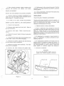
1. Place steering handle in straight- ahead position.
This maintenance manual contains service instructions
for Ski - Daddler Models SD18E24A (Mark 23), SDl8E25A (Mark 26) and Mark III, Models 5815-1100A and
-2000A.
Where differences exist between the four
models, each variation will be covered separately and
so noted.
2. Remove hood assembly.
3. Remove screw (figure 2), three spacer bushings
and bottom spacer securing the drag link and tie rod
to the spindle arm .
4. Loosen jam nuts securing rod- end bearings to the
drag link and tie-rod assemblies.
CHASSIS
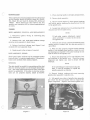
HOOD ASSEMBLY, REMOVAL AND REPLACEMENT
NOTE
1. Disconnect ignition wiring at connecting plug
below dashboard.
If both skis require adjustment, repeat
above procedure to loosen the tie rod on
the opposite ski.
2. Release left- and right- hand holddown straps
securing hood assembly to main frame.
5. Move ski into proper position and check the measuring pOints to ensure that the skiS are parallel to
each other.
3. Release front- hood release knob (figure 1) and
carefully lift hood assembly clear.
6. With the skis properly aligned and the steering
handle in the straight-ahead position, rotate the rodend bearings as required to bring the bearings in line
with the holes in the spindle arm.
4. Replacement is the reverse of removal.
HOOD ASSEMBLY, REPAIR
c
Fiber- glass repair material can be purchased locally
from any auto- or marine-supply store. Follow directions on kit carefully when making repairs.
7. Se(;ure the drag-link and tie- rod assembly rodend bearings to the spindle arm. Check for proper
alignment and tighten jam nuts to secure rod-end
bearings.
NOTE
STEERING
The skis should be parallel to one another and the sled
when the steering handle is in the straight- aheadposition. The inside edges ofthe front and rear of the skis
should be eqUidistant. If the skis or steering mechanism are not properly aligned, adjust as follows :
If the preceding procedure fails to align the
skis, it will be necessary to adjust the
spindle assembly as follows:
8. Remove locknut, washers and screw securing
spindle-tube assembly to spindle arm.
g, Lift spindle arm clear of spindle-tube assembly
and rotate the ski and spindle tube as required for
proper alignment. ReplaCe and secure spindle arm.
c
Figure 2
Figure 1
1
10. Recheck alignment and replace hood assembly.
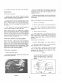
3. Place a straightedge on the fixed face of the drive
clutch and move the engine until the offset between the
straightedge and the front and rear edges of the driven
clutch is 1/4 inch.
POWER TRAIN
)
DRIVE-BELT TENSION
4. Tighten engine holddown nuts and check alignment.
Rotate driven clutch 90 degrees and repeat procedure
if necessary.
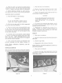
1. Loosen three bolts marked A (figure 3) and the
two nuts securing the lower chain housing to the main
frame. DO NOT loosen bolts marked B.
2. Loosen locknut C and turn adjusting bolt D clockwise to tighten the drive belt. To loosen the belt, turn
bolt D counterclockwise and move the chain case to
the rear. Turn in the adjusting bolt and secure with
the locknut.
DRIVE CHAIN REMOVAL AND REPLACEMENT
3. When proper belt tension is achieved, tighten all
nuts and bolts including the two lower nuts.
3. Loosen chain adjustment bolt and push down to
slacken drive chain. Remove the cotter pin, nut and
washer.
1. Remove hood assembly.
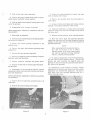
2. Remove chain- housing cover plate (see figure 4).
NOTE: Proper t ension for a NEW belt is obtained
when clutch centers are spaced 10-3/4 inches apart
(figure 3A) . Proper tension for a used belt is obtained
when the opposite sides of the belt can be squeezed
together to within 2-3/4 to 3-1/4 inches of each other
at the drive clutch (see figure 3).
4. Remove chain and sprocket.
5. Chain replacement is the reverse of removal.
Before assembling chain-housing cover plate, pack
chain housing with 1-1/2 pints of No.2, lithium bearing
grease. Adjust drive chain as outlined in following
procedure.
DRIVE BELT REMOVAL AND REPLACEMENT
DRIVE - CHAIN ADJUSTMENT
Remove the hood. Relieve belt tension by following
step 1 of the preceding procedure. Remove the belt
guard and the drive belt from the driven-clutch sheave.
Remove the other end from the drive clutch sheave.
Install the replacement belt in reverse order. Mter
replacement, check drive-belt tension as outlined in
steps 2 and 3 of the previous procedure.
).
1. Remove chain-housing cove r plate (figure 4).
2. Check drive chain for slack. Aproperlyadjusted
chain should have 1/8- to 1/ 4- inch slack.
3. If chain slack is greater than 1/4 inch or less
than 1/8 inch, loosen the locknut under the chainadjustment bolt. Push the bolt up to tighten the chain
or down to loosen the chain.
DRIVE-BELT ALIGNMENT
1. Remove the clutch guard.
NOTE
2. Loosen the four bolts securing the engine to the
engine mount (figure 3A).
The drive-clutch cam contains 3 threaded
holes for the ;tdjustment bolt. If necessary,
relocate the bolt to obtain proper chain
tension.
DRIVEN CLUTCH
•
'oRlVE CLUTCH
~
L-VIEWG
Figure 3A
Figure 3
2
ENGINE HOLOOOWN NUTS
V1EWO
9. Replacement is the reverse of removal. Pack the
bearings in the chain-adjusting cam with No.2, lithium
bearing grease.
4. When properly adjusted, tighten locknut on adjustment bolt securely and r eplace cover plate.
BRAKE ADJUSTMENT
10. During reassembly, follow drive - belt and d r iving
chain adjustment procedures.
Remove the hood assembly and proceed as follows:
TRACK GROUP
1. Remove cotter pin and tighten castellated nut on
brake arm until the brake pad just clears the driven
pulley (figure 3). Reinstall cotter pin.
TRACTION-BELT TENSION ADJUSTMENT
Traction-belt tension should be checked regularly . A
properly tensioned belt should have a 1- to 1-1/ 4-inch
sag at the approximate top center of the belt. This
dimension is determined as follows :
2. If brake is too tight, reverse the procedure.
DRIVEN CLUTCH REMOVAL AND REPLACEMENT
1. Remove hood assembly.
1. Place the s led on a clean, flat surface.
2. Remove clutch guard and drive belt. Refer to
previous procedure.
3. Remove drive chain.
cedure.
2. Place a sufficiently long, s traight bar along the
top surface and near the edge of the traction belt (see
figure 5) . Check for the 1- to 1- 1/4- inch sag at the
approximate center between the drive and idler shafts.
Repeat this procedure on the opposite side and note the
difference in belt tension.
Refer to previous pro-
4. Remove the spacer washer between the sprocket
and bearing.
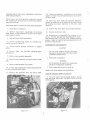
3. If adjustment is necessary, loosen locknuts (1,
figure 6) sufficiently to permit movement of beltadjusting angle (2).
5. Disconnect the brake cable by loosening the screw
on the brake. Remove the cable and spring.
c
4. If measurement exceeds 1-1/4 inches, turn ad justing screw (3) clockwise to tighten belt tension . If
measurement is less than 1 inch, turn adjusting screw
(3) counterclockwise to relieve tension. Adjust both
sides equally to maintain proper belt alignment.
6. Remove the screws, spacers and nuts securing
the disc-caliper brake components.
7. Remove the driven clutch assembly. The outer
bearing will be released.
8. Remove the inner bearing and grease seal.
5. Set sled on kickstand.
WARNING
Do not run Ski-Daddler engine in an en closed area unless properly ventilated.
TRACTION BELT
c
Figure 4
Figure 5
3
1. Place the sled on the kickstand.
6. Start the engine and permit the traction belt to
rotate several turns. Stop the engine and repeat steps
1 and 2 to ensure that proper tension is maintained.
2. Remove the locknut securing the center ogi c
wheel on one side only and remOve the wheel.
7. Before tightening locknuts (1), check tractionbelt alignment as outlined in the following paragraph.
3. Remove the opposite center wheel and axle as a
unit through the support assembly.
TRACTION- BELT ALIGNMENT
CAUTION
1. Place Ski-Daddler on the kickstand.
As the axle shaft passes through the cente r
of the support assembly, the center bogie
wheel will fall free.
Do not lose the
bushings.
WARNING
Do not run Ski-Daddler engine in an enclosed area unless properly ventilated.
4. To remove the remaining bogie wheels, r e move
the locknut securing the bogie wheel to the axle shaft
and then remove the wheelso
2. Start and run engine until the clutch engages and
the traction belt turns SLOWLY.
3. While the traction belt is turning SLOWLY, stand
to the rear of the sled and note the position of the
sprocket teeth in the traction-belt slots and the clearance between the traction belt and the support arms
on each side of the sled.
5. Reassembly is essentially the reverse of removal. However, be certain the wheel bushings are
properly positioned when inserting the axle shaft
through the support assemblies.
MP.RK III
4. If traction belt is not centered, loosen locknuts
(1 , figure 6) securing belt-adjusting angle (2) on each
side of the sled. Tighten adjusting screw (3) on the
side on which the traction belt is closer to the support
arm until the track is centered.
1. Place sled on kickstand.
2. Remove locknut securing bogie wheel assembly to
axle shaft.
5. Check traction-belt tension as described in the
previous paragraph and then tighten locknuts (1).
3. Remove bogie wheel.
4. Reassembly is the reverse of removal.
BOGIE WHEEL ASSEMBLY, REMOVAL AND RE PLACEMENT
BOGIE WHEELS AND SPRING ASSEMBLY, REMOVAL
AND REPLACEMENT
MARK 23 and MARK 26
1. Place sled on kickstand.
The front bogie-wheel assembly contains five wheels.
To remove the center bogie wheel proceed as follows :
2. Remove the bogie wheel assembly by removing
bolt (figure 7) and washer from each end of the bogiewheel support shaft.
Figure 7
Figure 6
4
)
c
3. Pull out the bogie -wheel assembly.
3. Loosen the chain-adjustment locknut and push
down to slaCken drive chain.
4. Remove the support shaft which holds the bogie wheel support assembly halves together.
4. Remove the sprocket from the drive shaft; remove chain.
5. Pull the bogie-wheel support halves apart to remove the springs.
5. Loosen traction-belt takeup and release torsion
springs. Drop takeup assembly clear of belt.
6. Reassembly is the reverse of removal.
6. Using a screwdriver, carefully pry the oil seals
(figure 8) away from the ball bearings at each end of
the drive shaft.
REAR SPROCKET ASSEMBLY, REMOVAL AND RE PLACEMENT
1. Place sled on kickstand.
7. Remove bearing retainer from right side of sled.
80 M,we the drive shaft and sprocket assembly
toward the right side until the shaft clears the bearing
retainer on the chain housing. Remove drive shaft and
sprocket assembly.
2. Relieve traction- belt tension by loosening adjus ting screws (3, figure 6).
3. Unlock the torsion springs connected to the
support arms.
NOTE
When replacing the dri ve-sprocket assembly, add 1-1/2 pints of No. 2 lithium
bearing grease to the chain-case housing
and coat the sprocket bearings liberally
with No.2 lithium bearing grease.
4. Remove the right- and left- hand adjusting angle
locknuts (1).
5. Remove the rear sprocket ass embly.
6. Remove the support arms if necessary to replace
bearings, seals and sprockets.
c
9. To replace the sprocket, remove the ball bearing,
oil seal and oil-seal retainer spring. Remove the
screws and nuts securing the support plate and
sprocket to the drive shaft and sprocket-plate assembly; remove the sprocket.
7. Remove press-on bearings and grease seals .
8. Remove screws and nut securing sprocket plate
and sprocket.
10. Reassembly is the reverse of removal. Follow
instructions for traction-belt tension and drive-chain
adjustment and traction-belt alignment. Be sure to
pack chain case and sprocket bearings with No.2
lithium bearing grease.
9. Reassembly is the reverse of removal. During
reassembly follow instructions for traction-belt alignment and adjustment.
DRIVE-SPROCKET ASSEMBLY, REMOVAL AND REPLACEMENT
1. Remove the hood assembly and set the sled on its
right side.
2. Remove the chain-housing cover plate.
c
Figure 8
Figure 9
5
12. Using a screwdriver, carefully pry the oil seals
(figure 8) away from the ball bearings at each end of
the drive shaft.
GREASE SEALS AND BALL BEARINGS, REiVIOV AL
AND REPLACEMENT
Follow rear- and drive-sprocket assembly removal
and replacement instructions to remove and replace
seals and bearings.
13. Move the drive shaft and sprocket assembly
toward the right side of the sled until the shaft clears
the bearing and plate ass embly in the chain case
(figure 9).
TRACTION BELT, REMOVAL AND REPLACEMENT
14. Remove the drive shaft and sprocket assembly.
1. Place sled on kickstand.
2. Remove bogie- wheel assemblies by removing
bolts (figure 7) and washers from each end of bogiewheel support shafts.
15. Remove the traction belt.
16. Replacement is essentially the reverse of re moval. Coat the sprocket bearings and pack the chaincase housing with 1- 1/2 pints of No. 2 lithium bearing
grease. Align the traction belt and adjust traction belt
and drive chain tension.
3. Pullout bogie-wheel assemblies.
4. Relieve traction-belt tension by loosening adjusting screws (3, figure 6).
CARBURETOR ADJUSTMENTS
5. Unlock torsion springs connected to support
arms.
6. Remove
locknuts (1).
right-
CAUTION
Do not force mixture screws into seats.
Damage to the seat may occur and impair
carburetor performance.
and left- hand adjusting-angle
7. Remove rear sprocket assembly.
1. Place sled on kickstand.
8. Remove hood assembly and place sled on right
side.
WARNING
Do not operate the engine in a closed area
unless it is adequately ventilated.
9. Remove chain-housing cover plate.
2. Start engine and permit to warm up.
10. Loosen chain- adjustment locknut and push down
on bolt to slacken drive chain.
HIGH- AND LOW-SPEED ADJUSTMENTS
11. Remove the sprocket from the drive shaft.
Mark 23 (Tillotson HR24A Carburetor)
1. Turn the high- and low-speed mixture screws
into the seats (figure 10). DO NOT FORCE SCREWS
INTO SEATS.
Figure 11
Figure 10
6
c
2. Open the high-speed mixture s crew from 1- 1/16
to 1- 3/ 16 turns.
3. Start the engine and set the idle speed at 1400 to
1700 RPM by adjusting the idle screw.
3. Open the low- speed mixture screw from 3/4 to
7/8 turns.
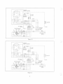
ELECTRICAL SYSTEM
MARK 23
NOTE
Figure 13 shows the electrical circuitry for the Mark
23 Ski- Daddler.
Carburetor settings should never deviate
from those specified unless warranted by
high- altitude conditions.
MARK 26
Mark 26 (Tillotson HR42A Carburetor)
Figure 14 shows the electrical circuitry for the Ma.rk
26 Ski- Daddler.
1. Turn the high- and low-speed mixture screws
into the seats (figure 10). DO NOT FORCE SCREWS
INTO SEATS.
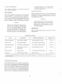
MARK III (5815-1100A)
Figure 15 shows the electrical circuitry for the Mark
III, Model 5815 - 1100A Ski-Dadd1er.
2. Open the high- speed mixture screw 1- 5/8 to
1-7/8 turns.
MARK III (5815-2000A)
3. Open the low-speed mixture screw 3/4 to 7/8
turn.
Figure 16 shows the electrical circuitry for the Ma.rk
III, Model 5815-2000A Ski-Daddler.
NOTE
HEAD LAMP ASSEMBLIES
c
Carburetor settings should never deviate
from those specified unles s warranted by
high- altitude conditions.
Mark 23 and Mark III, Model 5815-1100A
When replacing the headlamp, use a 12-volt, 18-watt,
GE No. 4414 bulb or equivalent.
Mark III (Tillotson HD15A Carburetor)
1. Turn the high- and low- speed mixture screws into
the seats (figure 11). DO NOT FORCE SCREWS INTO
SEATS.
Mark 26 and Mark III, Me de1 5815-2000A
l
When replacing the headlamp, use a 12-volt, 60-watt,
GE No. 4466 bulb or equivalent.
2. Open the high- speed mixture screw 1- 1/8 to
1- 1/4 turns.
3. Open the low- speed mixture screw 3/4 to 7/8
turn.
NOTE
Carburetor settings should never deviate
from those specified unless warranted by
high-altitude conditions.
IDLE-SPEED ADJUSTMENT
1. With the engine not running, turn the idle screw
(figure 12) until it contacts the throttle arm . Turn the
screw one additional turn.
2. Place sled on kickstand.
c
WARNING
Do not operate the engine in a closed area
unless it is adequately ventilated.
Figure 12
7
)
KOHLER
K 399 - T2 ENGINE
FUSE
MOLl5
BROWN
)
BLUE
BLUE
BATTERY
I
I
I I
I
, : ;-J
TAILLIGHTC]~~(s
DE
$g
~
C
- EN~NE
t:
IGNITION SWITCH
OFF
LIGHTS
ON
(S
~
NO. 67
~ ~
FRAME
J
-
50
~
BLUE
WHITE
R N
ENGINE
;r;
BATTERY
CHARGE
UNIT
(
530
18 WATT
ORAN
GE 4414
BLACK
Figure 13
)
KOHLER
K399- T2 ENGINE
FUSE
MOLl5
BROWN
BLUE
BLUE
I I
I I
)
BATTERY
I
I
I I
I
, : ;-J
TAILLIGHTC]Z Ij!
NO. 67
IGNITION SWITCH
OFF
~ FRAME
LIGHTS
ON
~ffiC,!)~ffiffi
~ a ~ ra
¥
r
¥
_
D
RED
-
,ENGINE
~
I
BLUE
WHITE
R EN
~
~
RED
WHITE
HEADLIGHT
ORANGE
60 WATT
GE4466
BLACK
A K
Figure 14
8
ENGINE
BATTERY
CHARGE
UNIT
~
c
CABLE ASSEMBLY
SOLENOID
ASSEMBLY
,O FF
I---
BLACK
BLACK
12 VOLT
BATTERY
YELLOW
YELLOW
+ FUSE
B~;;: ~YELLOW
1
BATTERY
CHARGE
ASSEMBLY
1-
ON
L-
1
LITE
START
(MOM CONTACTI
1
~
1
1
HARNESS
•
•
1
1
J~
RED
TAILLIGHT
S
. •- - 0
IGNITIO N SWITCH
HEAOLIGHT
(8 WATT, GE - 4414
BLUE
WHITE
Figure 15
c
r
OFF
1- LITE
ENGINE
1- ON
J- START
(MOM. CONTACT)
BLACK
I
BLACK
~
YELLOW
YELLOW
YELLOW
(~l~
TAILLIGHT
I. •
-1-, *
~
I
RED
I
ENGINE
J~
--)
'- - -
•
o
..J
..J
w
=>
m
'"
U
..J
«
>-
m
RED
IGNITION SWI T CH
..J
HEAD
LIGH T
WHITE
c
S
~
;e
w
Figure 16
9
or multivisocosity oils. Use a good grade
of regular gasoline; do not use gas left
over from summer uses.
T AILLAMP ASSEMBLIES
When replacing taillamps, use a 12-volt, 6-watt, GE
No. 67 bulb or equivalent.
)
OILS AND ADDITIVES
FUE L MIXTURE
Fuels containing additives are not recommended for
Ski-Daddler engines. A small amount of DRI-GAS or
equivalent may be added to the fuel mixture if moisture
in the system is evident.
The correct gasoline- to-oil ratio is 20: 1 (20 parts
regular gasoline to 1 part SAE 30- or 40-weight oil.
If using AMF oil, use 32 parts regular gasoline to 1
part oil for the first 25 hours of operation and 40 parts
regular gasoline to 1 part oil thereafter. For severe
service conditions, always use the 32-to-1 mixture.
CAUTION
Some outboard motor oils contain detergents that work well in low-temperature,
water-cooled outboard engines.
These
detergents may cause spark plug fouling in
air-cooled engines.
CAUTION
Gasoline and oil should be mixed at temperatures above freezing. Below freezing
gas and oil mix with difficulty. Mix with
care or engine damage may result. Use a
good grade of SAE 30- or 40-weight, nondetergent. oil, AMF oil or a good grade of
two-cycle engine oil. Do not use light-duty
LUBRICATION
Refer to the lubrication chart for periodic lubrication
requirements.
LUBRICA TION CHART
PART
TYPE OF LUBRICANT
LOCATION
FREQUENCY
Steering spindles
Zerk fitting on spindle
Low-temperature grease
50 hours
Drive chain
Chain-case housing
No.2 lithium bearing grease
40 hours
Sprocket bearings
Front and rear sprockets
No.2 lithium bearing grease
40 hours
Bogie wheels
Zerk fitting in center of
bogie wheel
Low-temperature grease
25 hours
Driven clutch
Clutch bearing
No.2 lithium bearing grease
Yearly*
Steering
End of steering column
Light engine oil
50 hours
*Pack driven clutch bearings each winter prior to initial startup or in the spring when preparing sled for
summer storage.
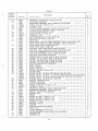
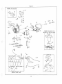
ILLUSTRATED PARTS LIST
The follOwing parts list is provided to facilitate the
procurement of spare parts and sled disassembly. This
list covers four Ski-Daddler models: the SD18E24A
(Mark 23), SDl8E25A (Mark 26), and the Mark III,
Models 5815-1100A and -2000A. Where parts are common to all four sleds, no model number designation
follows the part description. Where parts apply to
specific sleds, the applicable deSignation will follow.
10
)
Figure 1
c
.. - - ----r-- - - - , . - -- -- -- - - -- -- - -- -- -- - -- - - - -- - - -"-T""-----,
};igurc
~ Index
j 0JUll1 bel'
1 -1
-2
3
-4
-5
-6
-7
-8
-9
- 10
- 11
c
- 12
- 13
-14
-15
-16
- 17
-18
- 19
-20
- 21
-22
-23
-24
-25
-26
- 27
- 28
- 20
- 30
-31
-32
- 33
- 34
-35
-36
- 37
-38
- 39
c
-40
- 41
Description
Qty
Part No .
123 4 5 6 7
33358
33357
34128
34129
30250
125680
125680
9000556
31157
38403
34559
38404
33386
33402
33403
32253
30272
30285
34270
34270
132911
33579 - 2
34570
30268
34569
34573
33033
33644
24180
33646
34154
34152
30229
30270
30489
34105
.... . . ...... ... ... .. . .... . . .
WINDSHIELD (Used on Mark 23 and 26)
WINDSHIELD (Used on Mark III)
. . .. . .. ... . . .. . . . .. .. . . .. . " .. . .. .. .
TRIM STRIP, Windshield RH (Used on Mark 23 and 26)
. .. . .. . . . .. .. .. .
TRIM STRIP, Windshield LH (Used on Mark 23 and 26)
..... . ... ... . .. .
TRIM STRIP, Windshield (Used on Mark III)
. .. . ...... ...... . . .. . .. .
SCREW, Truss HD, 1/ 4 - 20 by 5/ 8 (Used on Mark 23 and 26)
. ... , .. .
SCREW, Truss HD, 1/4-20 by 5/ 8 (Used on Mark III)
. . . ... .... ... .. .
NUT, Jack, 1/4-20 (Used on Mark 23 and 26)
... . . ... . .. .. ... . ... . . . .
RNNUT, 1/4 - 20 (Used on Mark III)
... . . .. . . . ... . ... .. .. . .. . .. . .. . .
HOOD AND HEADLIGHT ASSEMBLY (Used on Mark 23 and 26)
. . . ... . .
HOOD AND HEADLIGHT ASSEMBLY (Used on Mar k III)
. .. .... . . .. .
FRONT SHROUD (Used on Mark 23 a nd 26)
... ... . ... . .. . .. .. ..... .
FRONT SHROUD (Used on Mark III)
.... . . . . . . . ....... . .. .. . . ...... .
LID , Glove box (Used on Mark 23 and 26)
. . ... ... . . . . .. . ...... . ... . . .
... . ... .. ..... . ....... . .... .. . . .
LID , Glove box (Used on Mark III)
LA TC H CLIP, Glove box lid
.... .. .. .. . . . . .. .. ... . .. .... .... . .. .. .. .
HINGE, Glove box lid
" .. . , .. .. . .. .. . ...... '" ... .. ... . .. . ..... . .
PLAT E, Glove box iid
.... . . ... .. .. . .. . .. . ..... ... . .. ..... . ..... "
POP RNET (Used on Mark 23 and 26)
. .... . .. . .. .... . .. ... . . . ... .
POP RNET (Used on Mar k III)
.. . . .. ... •.. ..•.. . .... . .•.. . .. .. . . . .
SCR EW, RD HD, 10 - 32 by 5/8
. . ..•.. .. .. ... . . .. .. ... .. . . . .... . . ..
LOCKNUT, 10 - 32
.. .. ... ...... . . ....... .. . . . .. . .. . . ... . . . .. . .... .
GAS CAP AND INDICATOR ASSEMBLY (U s ed on Mark III)
. . . ... . . .. . .
GAS CAP (Part of 34 570)
. .. .. ... . . .. .... .. ..... .. . ..... . ... . .. . .
CHAIN, Gas cap (Par t of 34 570)
... .......... . ..... . .. ... . " . . . .. .. .
INDICATOR, Fuel level (Par t of 345 70)
. ...... . . ... .. ..... .. .. . ... .
GROMMET, Hood (Used on Mar k III)
.. .. . . .. . ..... . .. . ... . . . ..... . . .
FUEL INLET TUBE ASSEMBLY (Used on Mark III)
. . .. . . ... . .. ... ,
HOSE CLAMP (Used on Mark III)
..... . . . . ....... ..... .. .. . . .. . .... . .
CONNECTOR, Fuel inlet tube (Used on Mark III)
. ..•. . .. .. . . .. . . ....
GASKET, Gas tank outlet (Used on Mar k III)
... . ... . . . . .. .... . ..... .
GAS OUTLET, Gas tank (Used on Mark III)
.. .. .. ... .. .... . . ..... . .
GAS LINE, Tank to carbur etor (Used on Mark III)
. ... .. . . . " . .. " .. . .
GAS LINE, Gas tank (Used on Mark III)
.... .. ... .. ... . . . .. .. . . .. . . .
CLAMP (Used on Ma r k III)
•. .. .... . . . . .. .... .... ...... ... ........ .
FILTER, Fuel tank (Used on Mark III)
. . .... . . . .. .. ...... . ....... .
MAIN FRAME ASSEMBLY (Used on Mark 23 and 26)
... ... .. ..... .. .
. .. . ... . .. . .
MAIN FRAME ASSEMBLY (Used on Mark III, 5815-1100A)
MAIN FRAME ASSEMBLY (Used on Mark III, 5815 - 2000A)
..... . . . . . . .
BUMPER, Rubber (Used on Mark 23 and 26)
.. . ... . ... . . . . . .. . ..
BUMPER, Rubber (Used on Mark III)
... .. . .... ..... . ... . .. .. . . .... . .
TRIM, End cap RH
. . .. . . .. . . .. . . .. . ....... . ....... . ...... .. ... . . . .
TRIM, End cap LH
. .. . .. . . . .. .. . . . .... .. . . . . . . .... . ....... .. . .. . . .
SCREW, Phillips HD, 1/ 4- 28 by 2
. ... .. . .. . . , . . .. . . .. . . .... . . . .. .
LOCKNUT, 1/ 4-28
...... ....... . .. .... . .... . .. . ..... . ... . . . . . ... . .
SPACER, End cap
. .. . .. ... .. . .. .. .. . . .. . .... . ... . .... . .. .. ... . . . .
SPACER
.. . ..... . .. . ...... . ... .. . .. . . . .. ... . . . ... . . .. ... .. . .... .
BUMPER (Used on Mark 23 and 26)
BUMPER (Used on Mark III)
..... .. . . ... . .. . ... . . . ........ . . . ...... .
SUPPORT
. . .. .. . . ....... .. . . .... . . ....... .. . . . . . .. . .. . .. . . . . .. . . .
BOLT, Curved HD, 5/16 - 18 by 5/8
. ....... ................ .. . . . . . .
NUT, 5/ 16 - 18
.. .... .... . . ... . .. ... ..... .. . . ... . .... . . ... .... . .. . .
WASHER, 5/ 16 . .. . .. . .. .. ... . .. ... .. . . ... . .... . ..... ... . . . . . .. .. . .
BOLT , HexHD, 5/ 16 - 18 by 1
. ...... ...... ... . ... . .. . .. . .... . ... .
SCREW, Hex HD, 1/4 -2 8 by 1/ 2 (Used on Mark 23 and 26)
. .... . .. ... .
SCREW, Hex HD, 1/ 4 - 28 by 1/ 2 (Used on Mark III)
. ... . .. 0 " , • • • • •
\VASHER, 1/ 4
.. . . . . .
LOCKNUT , 1/ 4 - 28 (Used on Mark III)
. ... .. ... ... . .. . . ..... . . . . . .
334~0
34006
34564
33788
33763
32986
32987
33852
33579-3
33853
33038
33787
33786
32537
27522
9413447
446363
126358
123316
123316
446188
33579 - 3
o
0
0
•
•
11
•
•
•
••
••
•
•
•
•
••
•
•
••
•
•••
••••
•••
••
•••••
•
•
•••
•
•
•
•
•
••
•••
••
••
••
•
••
,
•
•••
•••••
•••••
••
1
1
1
1
1
a
8
9
8
1
1
1
1
1
1
1
2
3
10
12
1
1
1
1
1
1
1
1
2
1
1
1
1
1
1
1
1
1
1
1
1
1
1
2
2
2
2
1
1
1
1
3
2
2
2
1
1
1
51,
62
63
~\
65
oo~~;:r t
61 64
,
/
/
66
\,- W ~'(
j,F=
5=/,5=
5:=53
~J G8~ ~n ~"
~5J
~58 ~-60
~-59
MARK 23 AND 26 - - - -....
2
1
3
----e .".
~4
12
13 "'-
• •
14
.,.,<>0
15"
"'
l
J
dJ. U~l1
"
......
N
L
51
~
r
\-\ \~-
~
Ym
cS<. i
~~6l-Y 2~
85
61
35
(
4039
r:::::
24
41
r-,
34
2~-- 20
36
(;1'
.04
@.
~ "
22
m--28
36 37
::=- ~-~
81
2
8 15 17
j.",)/ 80
<~d I
"tJ
/
19
~!
18~'
~
(f--21
41 48
81
44
33
~ 19
45
~~ \
~I
/ tVJ~~)- (J
61 68 6910
82
86
43
o
J
'¥
30 //~ ~
32
90
89
88
31
/~
?
2129 / '
Figure 1
u
\
38
Figure 1
c
Figur e
Part No .
123 4 5 6 7
1-41
-42
34036
30218
34522
134243
33579-1
38461
32321
32511
132908
33579- 2
33604
33394
33393
34115
33578
34100
33396
34229
34228
34117
34168
34177
34176
34154
34152
34105
33580
33583
33584
34024
134190
33699
133046
133056
133063
9414920
33647
33616
32252
33726-3
33579-3
33775
33774
33777
33778
32234
181573
181577
181578
33579-3
33808
446188
34159
34271
34237
34555
34000
34163
LOCKNUT, 1/4 - 28 (Used on Mark 23 and 26)
.....................•..
HEAD LAMP ASSEMBLY
........................................
HEADLAMP ASSEMBLY (Used on Mark III, 5815 - 2000A)
..... .. .. ...
SCREW, Oval HD, 8-32 by 1-1 / 4 .........•..........................
LOCKNUT, 8-32
.......................... ..........•....... . ...
CLUTCH GUARD ASSEMBLY (Used on Mark 23 and 26) ................
CLUTCH GUARD ASSEMBLY (Used on Mark III)
....................
CLUTCH GUARD SPRING P LATE
...............•......... . ......
SCREW, RD HD, 10 - 32 by 1/2
. ..•......•..... .•.. . .. . ...... ..... .
LOCKNUT, 10 - 32
...............•.............. • .................
SEAT BOTTOM (Used on Mark 23 and 26)
............................
SEAT BOTTOM (Used on Mark III)
.......•..•.....................
SEAT BACK
... • .........•.......•.....•.........•..............
REAR COVER AND TAILLIGHT ASSEMBLY (Used on Mark 23 and 26) ....
REAR COVER AND TAILLIGHT ASSEMBLY (Used on Mark III)
. 0......
REAR COVER (Used on Mark 23 and 26)
. . •. . . .. . . . . . . . . . . . . . . . •. . . .
REAR COVER (Used on Mark III)
. . . . . . •. . . . . . . •. . . . . . . . . . . . . . . . . . . . .
GAS LINE, Tank to tube (Used on Mark 23 and 26)
.. o • •
GAS LINE, Tube to carburetor (Used on Mark 23 and 26)
.....
FUEL GAGE ASSEMBLY (Used on Mark 23 and 26) ... ... ....... .......
GAS TANK WELDMENT (Used on Mark 23 and 26)
.......•....•.......
GAS LINE (Used on Mark 23 and 26)
....•.. . ..........•..
CHECK VALVE, Gas tank (Used on Mark 23 and 26)
.•........•.....
GASKET, Gas tank outlet (Used on Mark 23 and 26)
..••....•.......
OUTLET, Gas tank (Used on Mark 23 and 26)
..•...•.........•..•....
FILTER, Fuel tank (Used on Mark 23 and 26)
.•..•.....• . ...•.
BRACKET AND SOCKET ASSEMBLY
.....•...•....•.......•. 0.......
LENS, Taillamp
.....•.•.....••...•......•.................... .
BULB, Taillamp
. . . . . •. . . . . . . •. . . . . •. •. . . • . . . . . . . . . . . . . . . . . . . . • .
RIVET, 5/32 by 3/4
.••.•...•....•.
SCREW, Oval HD, 6-32 by 1 - 1/4 ...•.•.•.....•..••.•..••..• .,.......
GROUND WIRE ..••.... . •.... . •.•............... . ..................
SCREW, RD HD, 1/4 - 20 by 7/8 (Used on Mark 23 and 26)
............
SCREW, RD HD, 1/4 - 20 by 1 - 1/2 (Used on Mark III, Model No. 5815 - 1100A)
SCREW, RD HD, 1/4-20 by 2 (Used on Mark III, Model No. 5815-2000A)
WASHER, Plain, 1/2 OD (Used on Mark ill)
. . . .. . . .•. .. . . . . .. . . . .. .
SPACER, Kickstand bumper
•....•..•.•...•..•.....................
BUMPER, Kickstand
....•.....•.•.........•..•..•..........•... .
PLATE, Trailer hitch
.•.•.•••••.•.•....••.. ...•.••....••.•...•...
SCREW, Truss HD, 1/4-28 by 1 - 1/4
• ....•.•.•.•...•.•......•••.....
LOCKNUT, 1/4-28
...•.•.•...•••. 0................... 0............
KICKSTAND ASSEMBLY (Used on Mark 23 and 26)
...•...•.....•.....
KICKSTAND ASSEMBLY (Used on Mark III)
.• ••••••••.•••.. •••.•••.
SPACER, Long (Used on Mark III)
. . .•. .. . .. . . . .•.. . .. .•. .. . .. . . . .
SPACER, Short
•••.•••.••••..•.....••••.•••••.•.•..•.••.
SPRING
•••••.••• • .••...•••.•.
SCREW, Hex HD, 1/4-28 by 1 - 1/4
........................ .,......
SCREW, Hex HD, 1/4 - 28 by 1-3/4
...•...••....•.•..........•.•.•.
SCREW, Hex HD, 1/4-28 by 1 - 7/8
................. ,. .... ,. 0..... .
LOCKNUT, 1/4-28
•.•.•.•.•.....
.....•..••••.....•.•.•... . .............. . .......
WASHER, Formed
WASHER
................................................. . ......
HOOD HOLDDOWN WELDMENT
....................................
RIVET, Pop
....................................................
LATCH ASSEMBLY, Front hood
. ..... ........ .. . .. ... .. ... .... . ....
LATCH ASSEMBLY (Used on Mark III, 5815 - 2000A)
. ......... .. ....
RUBBER STOP . . . . . . . . . . . . . . . . . . . . . . . . . . . . . . . . . . . . . . . . . . . . . . . . . . . .
CENTER CLIP
. ......... ......... .... ....... ...... .. .... ..........
-46
-47
-48
-49
-50
-51
- 52
-53
- 54
- 55
- 56
-57
- 58
-59
-60
-61
- 62
- 63
-64
-65
-66
- 67
-68
-69
-70
- 71
-72
-73
-74
-75
- 76
-77
-78
- 79
-80
-81
-82
- 83
-84
-85
-86
c
Qty
Number
-43
-44
-45
c
Description
& Index
-87
-88
0
"
••••••
0
•
•
•
••••
••
0
•••••
•
•
•
•
•
•
•
0
•
•
••
•
•
•
0
0............................
0
0
0.... . .
0
••••••••••••••••••••••••
0
••••
0
•
•
•
0.................................
13
2
1
1
2
2
1
1
1
2
2
1
1
1
1
1
1
1
1
1
1
1
1
1
1
1
1
1
1
1
2
3
1
2
2
4
4
2
2
1
3
3
1
1
2
2
2
2
2
2
6
4
4
2
12
1
1
1
2
Figure 1
Figure
Desc r iption
& Index
Number
1-89
- 90
-91
Qty
Part No.
1234567
34155
34186
33957
STRAP, Holddown
.. . ........... ........ .. .. ........ . . .. ....... .. .
HOOK, Holddown strap
........ • ..... .... ..... .... ........ . . . . .....
GLOVE BOX ASSEMBLY (Used on Mark III)
. ...................... .
14
2
4
1
)
Figur e 2
c
Fi~ure
Description
&: Ind ex
Number
2-1
Part No.
33933
33667
34543
-2
-3
-4
-5
-6
-7
-8
-9
- 10
- 11
-12
- 13
c
-14
- 15
-16
-17
-18
- 19
-20
- 21
-22
- 23
- 24
- 25
- 26
- 27
-28
- 29
- 30
- 31
-32
- 33
-34
c
- 35
-36
-37
-38
-39
- 40
- 41
-42
-43
- 44
- 45
-46
- 47
-48
24054
181566
446188
33579 - 3
28416
33687
33651
30081
124925
33979-5
33689
33653
33927
34579
21777
21777
30251
995364
189329
181643
33634
33635
33698
30149
181620
274517
32186
32187
32188
9417420
142443
33579 - 2
34053
34052
38437
34511
34055
34512
34054
32286
33861
33710
181595
456145
33827
34044
33410
34058
446188
33444
33434
33662
33411
Qty
1234567
STEERING COLUMN AND HANDLE ASSEMBLY (Used on Mark 23 and 26)
STEERING COLUMN AND HANDLE ASSEMBLY (Used on Mark III, 5815l100A)
. ... " . .... .. ... .. .. . .. . . . .. .. ....... . .. .. ..... ... . .. " .
STEERING COLUMN AND HANDLE ASSEMBLY (Used all Mark III, 5815 2000A)
.. ... . .. . . . . . ... . .... . ..... . ... . . . .. . . . . . . . .. .. . . . . . .. . .
BRACKET
. ... . .. . . .... . . .. . . ... . ......... .. . .. . . . .. . . . .. . . .. . ... .
SCREW, Hex HD, 1/ 4 - 28 by 3/4
.. . ... . . . .. . ....... . . .. ... ..... .. . . .
WASHER , 1/4
. . . . . ........ .. .. .... .. ... . ...... .. . . . . .. .. . ..... .. .
LOCKNUT, 1/4- 28
... . . . . . . . ... .. ... . ... . ... . . . .. .. ... . .. . . .... .. .
HAND GRIP
. .. .. ... ... .... ..... .. . . .. .. . .. .. .. . .. ... . . . . .. .... .
TIE ROD (Used on Mark 23 and 2 6)
...... . .... . ... .. . . . . .. . . ... ... .
TIE ROD (Used on Mark III)
. .. ........ . ..... . .. .... ... . ... ........ .
ROD END
.. ...•.• ....... . ... . . . . . ..... . , . . .. . . . .. . . . .. '" '" .. . . .
NUT, Hex, 3/ 8-24
. .. .... . . .. . .. . .. . .. . ..... . . .. .... . ....... .. . .. .
LOCKNUT, 3/ 8-24
. ... .. .... . . .. . .. . . ... . .. . . .. .. '" .. . " .. .. .. . . .
DRAG LINK (Used on Mark 23 and 2 6)
. . . . . . . . . ... . . ... .. . . . .. .. . .
DRAG LINK (Used on Mark III)
... .. ..... ... .. . ..... . .... . .. .... .. .
STEERING COLUMN SUPPORT (Used on Mark 23 and 26)
. . .. .... . ' . .
STEERING COLUMN SUPPORT (Used on Mark III)
. . . . . . ... . . ... . ... . .
SPACER (Used on Mark 23 and 2 6)
. .. ..... ..... . ... . .. ...... ..... .
SPACER (Used on Mark III)
. . ... .. .. . . .. .. . . .... . . . .. .. ... . .. .. .. .
SPACER
..... . ... . .. . .. . . . . .. . . .. ... . .. .......... .. .... . .... . . . .
SCREW, Hex HD, 3/ 8 - 24 by 2-3/ 4
. . .. . .. .. . . .. . .. . .. ... . " .. . . .. .
SCREW, Hex HD, 3/ 8 - 24 by 3-1 / 4
. ... . . . ...... . ... . .. .. . .. .. .. .. .
SCREW, Hex HD, 3/ 8 - 24 by 1 - 1/ 2
... . .. . . ..... . .. ... . .. . .. . ..... .
SPINDLE ARM
. .. . ..... .... . .. .. . . . .. .. . . . . .. . . .. . .. . .. . . . .. . .. . . .
SPINDLE ASS E MBLY
. " . . ...... . ..... . ... . ..... .. .. .... .. . . .. .. .
GREASE FITTING
.... ...... .. .. ... . . . . .. . . . .... .. ...... . ... ..... .
SPINDLE SPRING
... . ................... ... ..... ..... . .......... .
SCREW, Hex HD, 5/ 16 - 24 by 2
... .. ... ... . . ......... .... . . .. . " . . .
WASHER, Plain , 3/ 8
.. . . . .............. . ......... .. ... .. . . . . ... .
CLAMP , Thumb control .. . . . . . ...... . ..... . ....... . ...... . ..... . . . .
THUMB LEV ER
.. • ... . .. . .. . •. • . •.• .. .. . • . . . . . ... ... . .... ... . . .
SPACER, Thumb lever
...... .. . .. . .. .. . . . . . . . .. .. . ... . . .. .. . . .... .
SCREW, Truss HD, 6 - 32 by 3/ 8
. . .... .. .. . .. .. .. .... . . ...... .... . . .
SCREW, Truss HD, 10 - 32 by 1-1/8
... . . .... . ...... " . " .. .. . .. . .. .
LOCKNUT, 10 - 32
. . . . . . . . ..... . .... . .. .. . . " ..... .. . . ..... . . . ... .
THROTTLE CONTROL CABLE
. ... . . . ... . . . .. . . ... . ...... .. ... . . . .
THROTTLE CONTROL HOUSING ..... . .. ..... .... .. . ......... . .. . . . .
REINFORCEMENT , Throttle cable
.. . . ..•. . .... • . . . . .... ... .. . .. ..
BRAKE CONTROL CABLE (Used on Mar k 23 and 26)
. .. .. .. .... ... . .
BRAKE CONTROL CABLE (Used on Mark Ill)
... . ......... ... . ..... . .
BRAKE CONTROL HOUSING (Used on Mar k 23 and 26)
. .. . .. ..... .... .
BRAKE CONTROL HOUSING (Used on Mar k III)
.. .. .. . '" .. .. ... . . .
CLIP
. .. . .... ... . . .... ........ .. ...... . ........ . .... . . .. .. . . . . .. .
BOOT, Throttle control
. .•. . • .... .. ... .. . . ...... . ... .. ... . .. ... ... .
BRAKE MOUNTING BRACKET ASSEMBLY
....... .. .... .... .... .. .
SCREW, Hex HD, 5/16-24 by 3/ 4
. . . . . ...... . ...... . . ... . . . ... . . .
WASHER, 5/ 16 .. .... . . . . . . . .. . .... .. .. ...... . . . . ... . ..... ... . .. . . .
DISC CALIPER BRAKE ASSEMBLY
.... .. ....... .. ........ .. . .. .. . .
BRAKE SPRING
. .... . . . .. .... . . ..... . ... ..... . .. .. ... . . .. . . . .. .
CHAIN HOUSING COVER ASSEMBLY
. . .... . .... . . . .. . .. . .... ... ... . .
LOCKNUT , 1/4 - 20
. .. .. .. ........ . ... . .... . ...... . .. " '" . ... .. .. .
WASHER, Plain, 1/ 4
.. .. .. ...... . . . ..... . .... . ... . .. . .... . .. . . . .
SCREW GASKET
..... .. .... .... .. . . ..... .. . .. .. .. . . ... . . . ... .. . .
GASKET, Chain case
. . . . . .... ... . . . . . . ... . . . . ... . . . .. ...... .. . . .
ROLLER CHAIN
. . . . .... . . .... . . . ... . .... .. .... . . . .... . .. . . . . .. .
CHAIN HOUSING WELDMENT
15
I
I
2
2
2
2
I
I
2
4
2
1
1
1
1
6
5
2
I
I
1
2
2
2
2
2
4
2
2
4
4
2
2
I
1
1
1
I
1
1
1
1
I
2
2
1
2
2
2
1
I
1
"
Figure 2
J
~3~ \\8
31
30
--=-~ ~
~
32------..--Ai
r
36
39
41
40
46
47
42
43
r(
45 44
7
68
67
16
Figure 2
c
Figure
Part No.
1234567
2 -49
-50
-5 1
- 52
-53
- 54
-55
33725 - 1
33579 - 4
456145
181595
125250
121224
33821
33822
32327
33892
34232
30184
33893
8290
38401
180126
124829
9417098
33976
33430
34006
34564
30228
187044
33579 - 5
181639
274517
33724
34218
337929
33730
33731
33296
33748
144518
28762
33297
33739
33744
33579 - 3
33746
34218
BOLT, Carriage, 5/16 -24 by 5/8
............................... .
LOCKNUT, 5/16 -24
..... .................. ..... ..... . . .... .. .. .
. ......... . ................................ .
WASHER, Plain, 5/ 16
SCREW, Hex HD, 5/16 - 24 by 3/4
. ....... . ...................... .
NUT, Slotted hex, 1/2-20
.....
COTTER PIN, 3/ 32 by 1
.... .. ............... .................. .
SPROCKET, 16 - tooth
..............
SPROCKET, 17 -tooth (Used on Mark III, 5815 -2000A)
... . . .. . .... . . .
............................................... .
WAVE WASHER
CAM
........................................................... .
SPACER WASHER
... .... .. ...........•...
O- RING
....................................................... .
OIL SEAL
.............•............•................ . ............
ROLLER BEARING
............................................... .
DRIVEN CLUTCH
............................................... .
SCREW, Hex HD, 3/8 - 16 by 1 - 1/2
....................... . ....... .
JAM NUT
. ................................................ ..... . .
..... .. .................. ............. ........ . .
WASHER, 1/2 ill
FORMED WASHER
..................... . ...................... ... .
............. . . .
MAIN FRAME ASSEMBLY (Used on Mark 23 and 26)
MAIN FRAME ASSEMBLY (Used on Mark III, 5815-1100A)
........... .
........... .
MAIN FRAME ASSEMBLY (Used on Mark III, 5815-2000A)
FOOT PAD
............................................. . ..... .
SCREW, Hex HD, 3/8-24 by 3 - 1/2
............................... .
LOCKNUT, 3/8 - 24
.............. ... ... ..... ... ......... ....
SCREW, Hex HD, 3/8 - 24 by 1-1/4
............
WASHER, 3/8
. ...... ......................... ............. . ... .. .
SPRING MOUNTING BRACKET
............... . ................... .
SKI PAD
......... . ............................... .... .... .. .... .
........... .
MAIN LEAF SPRING
MIDDLE LEAF SPRING
......•..... .. .................... . .........
TOP LEAF SPRING .. .. ... . .
SPRING PLATE
......................
SPRING PIVOT PIN ............................................... .
COTTER PIN
.......................................... . ........ .
PIVOT PIN
....•.........
RUBBER BUMPER
.. ... . . .......
SKI ASSEMBLY
............................................... .
SKI WEAR ROD ASSEMBLY
....................................... .
LOCKNUT, 1/4 -28
.....
SKI WEAR PLATE
...............
SKI PAD
.. .......
- 68
-69
- 70
-71
-72
-73
-74
- 75
-76
-77
- 78
- 79
- 80
- 81
- 82
- 83
-84
- 85
- 86
-87
c
Qty
Number
-56
-5 7
-5 8
- 59
- 60
-61
- 62
- 63
- 64
- 65
-66
- 67
c
Description
&: Index
0
••••••••••••••••••••••••••••••••••
0
••••••••••••••••••
0
•
•
•••••
•••
••
••
•••••
•••
••••••••
0
0
0
0
•
••••
•
•
•••••••
,
•••••••••••••••••••••••••
0
••••••••••••••••••••••
••••••••••••
•
•••••••••••••••
•
••••••••••••••••••••••••••••••••••••••
0
0
•••
•••
•••••••••••••••••••••••••••••••••••••
0
0
•
•••••••••••••••••••••••••••••••
•••••••••••
0
••••••••
••••
•••••••••••
,
••••
•
•••
••••••••••••••••••••
••••••••••••••••••••••••••••••••••••••••••••••
17
2
2
5
3
1
1
1
1
1
1
1
1
1
2
1
1
1
1
1
1
1
1
2
2
6
4
4
2
2
2
2
2
2
2
4
4
2
2
2
2
2
2
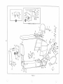
Figure 3
Figure
& Index
Number
3-1
-2
-3
-4
-5
-6
-7
-8
-9
-10
- 11
-12
-13
- 14
- 15
- 16
-17
- 18
-19
-20
-21
-22
-23
-24
- 25
-26
-27
- 28
-29
-30
-31
- 32
-33
-34
- 35
-3 6
- 37
-38
-39
-40
-41
- 42
-43
-44
- 45
- 46
-47
- 48
Description
Part No.
37072
33785
34107
33701
38446
33702
34207
33610
33610
38424
38425
34047
34048
38426
180121
131099
33930
33725-4
33579 -5
33780
34319
33782
33781
33780
33783
33725-3
456145
33579-4
33725-5
120426
120384
38432
38433
33829
33953
33579-3
33859
420998
30180
30176
30178
30375
120380
995246
34090
30270
34074
34070
34071
34076
34073
34075
34072
33951
2791
32591
37142
37143
1 2 3 4 5 6 7
Qty
KEY SWITCH (Used on Mark 23 and 26)
•.•.•.. ... .. ..••••..........
KEY SWITCH (Used on Mark m)
..••.•.•.•.•.•.•..........•...•.....
WffiING HARNESS (Used on Mark 23 and 26)
.•••.•...• ...• .....•....
WIRING HARNESS (Used on Mark ill)
............................... .
WIRING HARNESS, Engine (Used on Mark 23 and 26)
.......•........
WIRING HARNESS, Engine (Used on Mark m, 5815 - 1100A)
........... .
... .. ...... .
WIRING HARNESS, Engine (Used on Mark m, 5815 - 2000A)
CLIP, Wiring harness (Used on Mark 23 and 26)
•.•.•..••••••.......
CLIP, Wiring harness (Used on Mark m)
.•.... ....... .•. ............
ENGINE (Used on Mark 23)
.•..••.•..••........ .•..........•. . .....
ENGINE (Used on Mark 26)
.......•• . . ... .• .•• •. ..•.....•.•........
ENGINE (Used on Mark m, 5815-1100A)
.•.•...•..........•.........
ENGINE (Used on Mark ill, 5815 -2000A)
.•.....•.........•...•......
ENGINE MOUNT (Used on Mark 23 and 26)
......•.. •• ••.•.........
SCREW, Hex HD, 3/8-16 by 7/8 (Used on Mark 23 and 26)
.•..........
LOCKWASHER, 3/8 (Used on Mark 23 and 26)
....•..•..••.•.••.•.....
MOUNTING STRAP (Used on Mark 23 and 26)
.. • .....•....•...•......
BOLT, Carriage, 3/8- 24 by 2-1/4 (Used on Mark 23 and 26)
... . ... .
NUT, 3/8-24 (Used on Mark 23 and 26)
.................... .. ..... .
MOUNTING STRAP WELDMENT (Used on Mark m)
.•...••.........
REAR MOUNTING STRAP (Used on Mark m)
.•.•......•.....•.... .. .
ENGINE BASE PLATE (Used on Mark m)
....•......•......•.........
SPACER BAR (Used on Mark m)
.•.•••••..•.•.•.........•.•...... . . .
CHANNEL ASSEMBLY (Used on Mark m)
••.••..••.•••.•..••.........
TOP PLATE (Used on Mark ill)
..•.•.•.•...•.......................
BOLT, Carriage, 5/16-24 by 1 (Used on Mark ill)
. •......... .. .. .....
WASHER, Plain, 5/16
.••••• •• .••••••••••.... •. ........•.•.•.•.••.
LOCKNUT, 5/16-24 (Used on Mark m)
• . •••• •.•••...••. •.. ....... .
BOLT, Carriage, 5/1 6-24 by 1-1/2 (Used on Mark m)
" .• . ....... • ...
BOLT, Hex HD, 1/2 - 13 by 1-1/4 (Used on Mark ill)
.....•...•......
LOCKWASHER, Split, 1/2 ID (Used on Mark m)
•••..•••.•...•.. ... •
CARBURETOR (Used on Mark 23)
•••••••••••.•••••• .• •••••.• ...•.
CARBURETOR (Used on Mark 26)
••••••••••••• ..• ••.• .•.•.•.• . ...
CARBURETOR (Used on Mark m)
..•••••••....•...•.•••...•.•..•.
STUD (Used on Mark III)
••••••.•••...•.••••••.•••••••.••. .. • •...
LOCKNUT (Used on Mark m)
.• . •••.• . •••.••....•. •..•.•...•••...
COVER, Air intake (Used on Mark m)
.•••..•....•... . •...••......
SCREW, RD HD , 1/4-20 by 1-1/2 (Used on Mark III)
••••••••.••••...
MOUNT PLATE (Used on Mark 23 and 26) .•••.•••••.•.•.•.•... . ••....
SCREEN, Air cleaner (Used on Mark 23 and 26)
.•.••..•.•.•........
COVER , Air cleaner (Used on Mark 23 and 26)
..•...•.•..... ..... .
.•.•.......•.•...••.....
STUD, Air cleaner (Used on Mark 23 and 26)
LOCKWASHER, 1/4 ID (Used on Mark 23 and 26)
.....•...•..........
NUT, Acorn, 1/4-20 (Used on Mark 23 and 26)
. •........•...••.•.•
GAS LINE, Carburetor to engine (Used on Mark 23 and 26)
..•.....•...
GAS LINE, Carburetor to engine (Used on Mark m)
..•......... . " .
PRIMER VALVE (Used on Mark ill, 5815-2000A)
.•..•.• .......... . ..
TUBING, Rubber (Used on Mark m, 5815-2000A)
.••....• •. .... . . •. ..
TUBING, Rubber (Used on Mark m, 5815-2000A)
.••••••••••.•..••• • •
BULB, Primer (Used on Mark ill, 5815-2000A)
•••••.•..••.•.•.....
BRACKET (Used on Mark ill, 5815-2000A)
•••...••.....•.... .. ....
TEE (Used on Mark m, 5815-2000A)
....•.•...•............ .........
TUBING (Used on Mark ill, 5815-2000A)
.•.•.•...•.•..... . ..•.......
MANIFOLD, Carburetor (Used on Mark m)
.•.•...•....•.•.........
CLIP, Gas line (Used on Mark ill)
..•.•...•.....•.•.•.•...........
EXHAUST PIPE, Engine (Used on Mark ill)
........... . .. .... . ... . .
EXHAUST TUBE, Flexible, long (Used on Mark 23 and 26) .•.....•....
EXHAUST TUBE, Flexible, short (Used on Mark 23 and 26) ........... .
18
1
1
1
1
1
1
1
5
4
1
1
1
1
1
4
4
2
4
4
1
1
1
1
1
1
2
4
4
2
4
4
1
1
1
2
2
1
3
1
1
1
3
3
3
1
1
1
1
1
1
1
1
1
1
1
1
1
1
)
Figure 3
C
MARK 23 and 26
,.0.--40
39
';J
c{ 37 ~-41
')-38
___ 36
~
43~~42
1[63
45A
~
28
1: 62
27
59 58
-64
/
rr%1 24 26
~~ J
35--1
60
61
---
57
\ \
~ __ ~O-
~
44
1
~
c
I-j
7-1
I
9~ !
9-~
10-!
~~~
r---MARK III
20
17
~
-M(:
2
3
20~ ~
--'----::----~
8111'{M
{"ff
~15
~
'r-/'
MARK III, 5815-1100A
65
66
I ILo,
12~'~
~ /'
V A
21
' - - -MARK 23 and 26
Model 5818 only
c
-22
.......-
19
19
14
0
,I
~18
Figure 3
Figure
& Index
Number
3-49
-50
-51
-52
-53
-54
-55
-56
- 57
-5 8
-59
-60
-61
- 62
-63
- 64
- 65
-66
-67
- 68
-69
-70
-71
- 72
-73
-74
-75
-76
- 77
-78
-79
-80
- 81
- 82
-83
-84
-85
-86
-87
- 88
-89
-90
-91
-92
- 93
-94
- 95
-96
- 97
- 98
Description
Part No.
32588
32588
34033
38435
34032
181635
274517
33579-5
34031
38407
181709
189348
138549
38450
38460
37172
38436
34466
34516
123749
181575
33579-3
34050
33855
33856
32723
34515
33979
33984
34155
33982
34036
123316
446188
33579-3
123435
34029
436750
9417373
33579-2
34013
34014
34015
34020
34022
34021
33123
33855
33856
34050
34051
34016
34017
34106
38438
34110
34112
34113
34114
Qty
1 234 567
CLAMP, Flexible tube (Used on Mark 23 and 26)
.•.•••.•••••.•.•....
CLAMP, Flexible tube (Used on Mark ill)
........................... .
MUFFLER (Used on Mark ill)
................................... .
MUFFLER (Used on Mark 23 and 26)
.•.•...................••.......
BAND ASSEMBLY
.......•...•••••.•.•...•.•...•.....••..••......•
SCREW, Hex HD, 3/8-24 by 3/4
•..•.••......•.•...•.•....••.•.••...
WASHER, Plain, 3/8
.•••••••••.••.•.•.••.••••.•••..•.••.•..••...
LOCKNUT, 3/8-24
.•...•.•...•.•.•.•.••...•••..••...• •• ..•.•.•..•.
ELBOW, Muffler inlet (Used on Mark ITl)
... ......... .... ........ .. . .
DRIVE CLUTCH
..••••...•••.•........••••..••... •• •••.•....••..
BOLT, Hex HD, 1/2-20 by 2-1/2 (Used on Mark ill)
..•.........•...
BOLT, Hex HD, 1/2-20 by 5 (Used on Mark 23 and 26)
•.••••••••••.•.•
WASHER, Shakeproof
.•••...•••.•••.••••••••.•.••..•.•.•••.•.....
SPACER, Clutch
•••••.•••.•••.•••••••••.•.••.••••••..••.•.......
ADAPTOR, Bolt (Used on Mark ill)
•• .•.•..........................
VARIABLE SPEED BELT
.•. •••..••••••• ••••.•••.•.•••..•••......
THROTTLE WffiE BRACKET (Used on Mark 23 and 26) ...•...•• ••.•• ..
THROTTLE WIRE BRACKET (Used on Mark ill, 5815-2000A)
.••.••..
THROTTLE WffiE BRACKET (Used on Mark ill, 5815-1100A)
.•••.•.•
SCREW, Hex HD, 1/4-28 by 1-1/2
............................... .
SCREW, Hex HD, 1/4-28 by 1-1/2 (Used on Mark ill, 5815-2000A)
.•..
LOCKNUT, 1/4-28
••••••••••••••••••••••.••••.•.••.•••••••••.•••..
TERMINAL (Used on Mark 23 and 26) •..•••••...•...••••••••••.•..•.•
TERMINAL
., .•..•••.••.••.•.••••••••..••..•.••.••.•••.••••....
COVER
.•••.••..•.•...•.•••..•.••..•••••••••••.••••••••••..•..•
OUTLET CAP
•••.••.•.•.•••..••...•••••••••••••••••••••••••.••••.
BATTERY SUPPORT WELDMENT
............................... .
BATTERY ..•.•.•••.•.•••••••••••..••.•.••••••••.•••••••.•..•.....
HOLDDOWN ROD, Battery
..•.•.•..•..•.•••.••••••••..••••.•.•....
STRAP, Battery holddown (Used on Mark 23 and 26)
•••••.••••..•...
STRAP, Battery holddown (Used on Mark ill, 5815-1100A)
••••.••••...
LOCKNUT, 1/4-28
.•••.•••.•••••..•••••••••••.••.•••..••..•......•
SCREW, Hex HD, 1/4-28 by 1/2
.••••••.•••••.•....•..•••.•.•.••.•.•
WASHER, Plain
...•....•..••.•.••..•.•.•••••.•.•••.••.••..•.•..
LOCKNUT, 1/4-28
.••.••..••.•••••••••••.••.••••.•..•••..••.•.•...
SCREW, Hex HD, 1/4-28 by 5/8
................................... .
SOLENOID (Used on Mark ill, 5815 - 1100A)
..••.••..•.•••.•..••....
SCREW, Pan HD, 10-32 by 1/2 (Used on Mark ill, 5815-1100A)
••......
WASHER, Plain No. 10 (Used on Mark ill, 5815-1100A)
...•........
LOCKNUT, 10-32 (Used on Mark ill, 5815-1100A)
.................. ..
CABLE ASSEMBLY (Used on Mark ill, 5815-1100A and Mark 23 and 26) . •.
CABLE ASSEMBLY (Used on Mark ill, 5815-1100A)
.••••••••.•••...
CABLE ASSEMBLY (Used on Mark ill, 5815 - 1100A and Mark 23 and 26) ...
WffiING HARNESS, Hood (Used on Mark ill, 5815-1100A)
•.•.........
WffiING HARNESS, Engine (Used on Mark ill, 5815-1100A)
•.••...•... •
BATTERY CHARGE ASSEMBLY (Used on Mark ill, 5815 - 1100A)
....
BATTERY CHARGE UNIT (Used on Mark ill, 5815-1100A)
••.•••...••.
TERMINAL, Male (Used on Mark ill, 5815-1100A)
•...•••.........
COVER, Male terminal (Used on Mark ill, 5815-1100A)
•••••..••.•.
TERMINAL, Female (Used on Mark ill, 5815-1100A)
.••...••...• .. ..
COVER, Female terminal (Used on Mark ill, 5815-1100A)
••••..•....•
CABLE ASSEMBLY (Used on Mark 23 and 26)
....................... .
CABLE ASSEMBLY (Used on Mark 23 and 26)
...................... ..
WffiE ASSEMBLY (Used on Mark 23 and 26)
....................... .
STARTER MOTOR (Used on Mark 23 and 26)
••.•••••...•.••••.......
STARTER MOTOR (Used on Mark ill, 5815-1100A) ••••••••••••••.•.•..
BOLT (Used on Mark ill,' 5815-1100A)
........................... .
WASHER (Used on Mark ill, 5815-1100A)
........................... .
WASHER (Used on Mark ill, 5815-1100A)
...
0" .....................
20
.
4
2
1
1
1
2
2
2
1
1
1
1
1
1
1
1
1
1
1
1
1
1
3
3
3
1
1
1
2
2
1
2
2
4
2
2
1
4
4
4
1
1
1
1
1
1
1
1
1
2
2
1
1
1
1
1
2
2
2
)
c
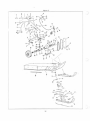
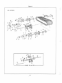
Figur e 4
Figure
& Index
Number
4- 1
-2
-3
-4
-5
-6
-7
-8
-9
-10
-11
- 12
- 13
- 14
-15
- 16
-17
-18
- 19
c
- 20
-21
- 22
- 23
- 24
- 25
-26
-27
-28
-29
- 30
- 31
- 32
-33
- 34
- 35
-3 6
-37
- 38
- 39
-40
- 41
- 42
c
- 43
-44
-45
- 46
Description
Qty
Part No .
1234567
37145
34960
33417
30145
30078
33717
181566
33579 - 3
33659
33413
33422
33725 - 1
33579 - 4
33821
181595
138485
33415
33905
33906
33754
33416
33711
33712
33721
33923
33713
33713
33736
33736
33907
33909
33419
33911
33908
33341
34140
33342
34141
322 66
32265
456145
33579 - 4
33725-2
33346
33347
33356
33357
181651
32237
33579 - 5
33705
33706
37196
37199
37144
30079
33417
37197
TRACTION BELT (Used on Mark 23 and 26)
... ... ...... . . . .. . ... .. .
TRACTION BELT (Used on Mark III)
...•....... . .................. . .
..................................... . .. ....... .
BA LL BEARING
RETAINER SPRING, Oil seal
.. . .. . .... . . . " .. ........ . .. .. . .. . . .
OIL SEAL
.......... .. .. ... . . . . .. . ........ ..... ....... . ........ .. .
SPROCKET SUPPORT PLATE
................................... .
SCREW, Hex HD, 1/4-28 by 3/ 4
..... .... . .... ... .. .. ......... . .... .
LOCKNUT, 1/ 4 - 28
.. ..... ... ..... .... ... . ... .. . .. .. . ............. .
SPROCKET, 9- tooth
...... • ....... .. ... . • ...• . .... ..............
DRIVE SHAFT AND SPROCKET PLATE
......... . ....... . .... ... .. .
.. . ...... . ..... . ... .
BEARING RETAINER AND PLATE ASSEMBLY
BOLT, Carriage , 5/ 16-24 by 5/ 8
.................. . ............ .
LOCKNUT, 5/ 16-24
......... . ........................... . .... . .
SPROCKET
. . .......... ....... . ..... .. .. . .. ... . ... . . .. .. . . .. . . .
SCREW, Hex HD , 5/ 16 -2 4 by 3/ 4 (Used on Ma rk III)
..... .. ........ .
WASHER, Shakeproof (Used on Mark III)
. .... . ......... ........... . .
BOGIE WHEEL AND SUPPORT ASSEMBLY (Used on Mark III)
.. . . .. . .
BOGIE ASSEMBLY, Middle and rear (Used on Mark 23 and 26)
. .. ... . .
BOGIE ASSEMBLY, Front (Us ed on Ma rk 23 and 26)
.. ..... . . . ... .. .
BOGIE WHEEL SUPPORT SHAFT (Used on Mar k 23 and 26)
. ........ . . .
... . .... . ..... . .
BOGIE WHEEL SUPPORT SHAFT (Used on Mark III)
TORSION SPRING, LH
............. .... ........ . ... .... . ......... .
TORSION SPRING, RH
... ............. . ........... . ... . ..... ... . . .
BOGIE WHEEL AND SUPPORT ASSEMBLY (Us ed on Mark III)
...... . .
BOGIE WHEEL AND SUPPORT ASSEMBLY (Us ed on Mark 23 a nd 26) ... .
BOGIE WHEEL (Used on Mark III)
. . .. .. . ..... . ... . ........ .. . .. . .
BOGIE WHEEL (Used on Mark 23 and 26)
...... ... ..... .. . ... . ...... .
LOCKNUT, 5/ 8-18 (Used on Mark III)
. , ..•.............. .. .......
LOCKNUT, 5/ 8 - 18 (Used on Mark 23 and 26)
...... . ............... . .
BUSHING (Used on Mark 23 and 26)
............ .. .. . ... , .. .. . .. . .. .
AXLE SHAFT (Used on Mark 23 and 26)
................. . ......... .
BOGIE SUPPORT ASSEMBLY (Used on Mark III)
. . •... ... . . ... . . . ...
BOGIE SUPPORT ASSEMBLY, LH
.. ..... ....... ... .. .... .... .. .. .
BOGIE SUPPORT ASSEMBLY, RH
. ..•.. .. ... .. .... . ..............
BELT ADJUSTING ANGLE, RH (Used on Mark 23 and 26)
........... .
BELT ADJUSTING ANGLE, RH (Used on Mark III)
• . .. ..... ... .. .. . .. .
BELT ADJUSTING ANGLE, LH (Used on Mark 23 and 26)
. . .. .. .... . .
BELT ADJUSTING ANGLE , LH (Used on Mark III)
................... .
ADJUSTING SCREW
. .............. ..... . ...... .. . . .. . . . ....... .
ADJUSTING BLOCK
....... ... ............ . .. .. . ..... ......... . .
WASHER, Flat
....................•............ . ... .... .. ... . . .. ..
LOCKNUT, 5/16 - 24
.. .. . . . ... .. .. .. . . ............... . ..... . . . . .
BOLT, Carriage, 5/16-24 by 3/4
. .. . .. . ... . . • ....... . .......... .
REAR SUPPORT ARM ASSEMBLY, RH
.............. . . ... . ....... .
REAR SUPPORT ARM ASSEMBLY, LH
. .. ...•...... . . ...... .. . . . ..
TORSION SPRING, Rear RH . . ....... ..... ...•... .. .... . ... . ....... .
TORSION SPRING, Rear LH
.. .... ........ .. ............. .... ..... . .
SCREW, Hex HD, 3/ 8 - 24 by 2 - 3/ 4
... .. . ......... ... ...... . .. .... .
RETAINER, Torsion spring
. ............ .. ....... . . ... ........... . .
LOCKNUT , 3/8 - 24
............................................... .
SPACER, Rear support arm
. ... ........•.... .. ...... .. ... . ...... ...
GREASE FITTING
.... .. . . . . . • .... . .... . .... ....... . ... .. . .. .. . . ..
REAR SPROCKET ASSEMBLY (Used on Mark 23 and 26)
...... .... . .
REAR SPROCKET ASSEMBLY (Used on Mark III)
......•..•..... . ....
SPROCKET
GREASE SEAL
BALL BEARING
CUPPED PLUG
21
1
1
2
2
2
2
18
18
2
1
4
4
1
6
6
3
2
1
3
3
3
3
3
3
12
13
12
13
4
1
3
1
1
I
1
1
2
2
4
4
2
1
1
1
1
2
2
2
2
2
1
2
2
2
2
Figure 4
ALL MODELS.
37
)D~ - ~
__ -~35~
28
11
6
). ~,~--Ir~1rr
'.~': .[1.12
10
2 3 4
5
8
5
19
MARK 2 3 and 26
22
----
F igur e 4
C
F igure
Desc ription
& Index
Qty
Nu m ber
Part No .
1 2 3 4 5 6 7
4-47
-48
-4 9
9000123
181566
37198
LOCKNUT, 1/ 4-28
................................................
SCREW, Hex HD, 1/ 4-28 by 3/ 4
...............
REAR SHAFT AND SPROCKET PLATE ASSEMBLY (Us ed on Mark 23 and
26)
. • ...•.•.•.•••.
REAR SHAFT AND SPROCKET PLATE ASSEMBLY (Us ed on Mark Ill) ....
SPROCKET SUPPORT PLATE
.•...............................
0
-50
37200
33717
••••••
c
c
23
•
••••••••••••••••
0
... ....
.
...
•••••
•
•••
0
•
•
•
•
•
•
•
•
0
•
•
•
•
•
•
•
•
•
•
•
•
•
•
18
18
1
1
2
Figure 5
)
2
6
'---------,"',.....--~
3
Figure
& Index
Number
5-1
-2
-3
-4
-5
-6
-7
-8
-9
-10
Description
Qty
Part No.
1 2 3 4 5 6 7
38407
37611
37612
37613
37614
37615
37616
37617
37618
37619
37620
DRIVE CLUTCH ASSEMBLY
FIX.ED FACE
MOVABLE FACE
••••••••••••••••••••••••••••••••••••••••
......... . ...•..... . . .... .•. . .• .•...•. ..• .•.•.•..•. .
1
1
••••••••••••••••••••••••••••••••••••••••••••••••
1
SPRmG KIT
•• • •••••••••••••••••••• •.•••••••• • ••••••• • ••••••••••
ROLLER KIT
.... .....•...•...•.•.......................•........
SPIDER
....•• .•.•..•............................... ...... . .....
RAMP PlATE
......... .. .•.... ...•..••........•......•..••.......
SPACER
•• ..• •• .......•.....•.•.... .... ............. •.. .. •......
SCREW KIT
••••••••••••••••••••••••••••••••••••••••••••••••••••
RETAIN'lli'G RrnG
.•••• ..•...•. •.•••••••.•.•.••••.•..••..•.••.•...
CUP WASHER
.•...•••.••....•••.•.•.•.•..••.•..•...•.•.........••
1
1
1
1
1
1
1
1
24
)
Figur e 6
c
2
Figure
& Index
Number
6-1
-2
-3
-4
-5
-6
-7
Description
Part No.
1 2 3 4 5 6 7
Qty
38401
37600
37601 .
37602
37603
37604
37605
37606
DRNEN CLUTCH ASSEMBLY
........•. • .... . .... ......•.........
FIXED FACE
.................................... . . . . •.. .........
MOVABLE FACE
...... 0............. ... ... ...... ...... .... ......
SPRING
........ .. .............. . ............. 0...... ... ........
KEY
....•.•.............•.•. • ....... . ...........................
BUTTON
................•.............. . ....... . ........ ".......
TORQUE BRACKET
............•...... . ........ .. .. .. ..
RET AINING RING
..•.•....•.........••......... . . •..
0
c
25
•
•
•
•
0
•
•
•
•
•
•
•
•
•
•
•
•
•
•
•
1
1
1
3
1
1